MSI x99s gaming 9 ac: English
English: MSI x99s gaming 9 ac

English
Thank you for choosing the X99S GAMING 9 AC Series (MS-7882 v1.X)
EATX motherboard. The X99S GAMING 9 AC Series motherboards are
®
based on Intel
X99
®
the advanced Intel
processor, the X99S GAMING 9 AC Series
motherboards deliver a high performance and professional desktop platform
solution.
®
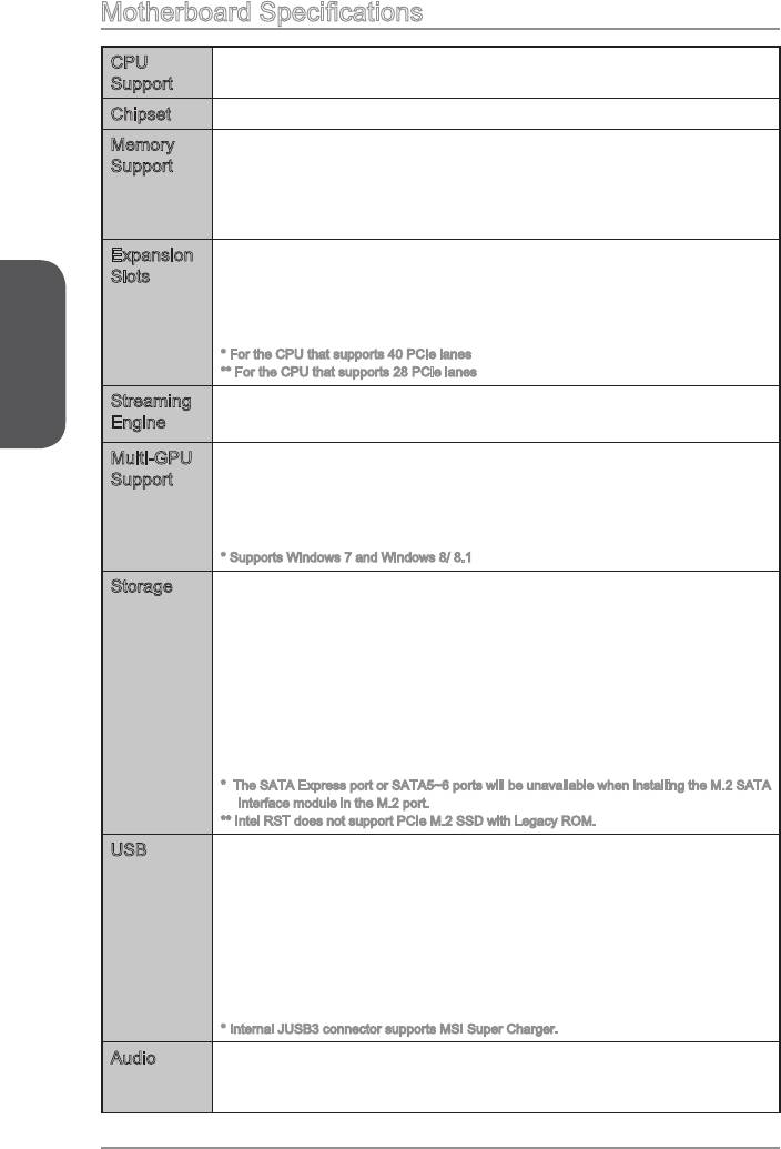
CPU
Supports New Intel
Core™ i7 Processor Extreme Edition for
Support
®
Chipset Intel
X99 Express Chipset
Memory
8x DDR4 memory slots supporting up to 128GB
Support
Quad channel memory architecture
Expansion
Slots
- 1-way mode: x16/ x0/ x0/ x0/ x0
- 2-way mode: x16/ x0/ x0/ x16/ x0*, 16/ x0/ x0/ x8/ x0**
English
-
- 4-way mode: x8/ x8/ x0/ x16/ x8*, x8/ x8/ x0/ x8/ x4**
* For the CPU that supports 40 PCIe lanes
** For the CPU that supports 28 PCIe lanes
Streaming
Supports H.264 hardware video/ audio encoding up to 1920x1080@
Engine
®
TM
Multi-GPU
Supports 4-Way AMD
CrossFire
Technology*
®
Support
Supports 4-Way NVIDIA
SLI™ Technology (For the CPU that
supports 40 PCIe lanes)
®
SLI™ Technology (For the CPU that
supports 28 PCIe lanes)
* Supports Windows 7 and Windows 8/ 8.1
®
Storage Intel
X99 Express Chipset
10x SATA 6Gb/s ports (2 ports reserved for SATA Express port)*
- SATA1~6 support RAID 0, RAID 1, RAID 5 and RAID 10
- SATA7~10 ports only support IDE mode and AHCI mode.
®
- Supports Intel
Smart Response Technology (Windows 7/ 8/ 8.1)
1x SATA Express port*
- M.2 port supports 4.2cm/ 6cm/ 8cm length module
- M.2 PCIe interface does not support RAID 0, RAID1, RAID 5 and
RAID 10.
* The SATA Express port or SATA5~6 ports will be unavailable when installing the M.2 SATA
interface module in the M.2 port.
** Intel RST does not support PCIe M.2 SSD with Legacy ROM.
®
USB Intel
X99 Express Chipset
-
- 6x USB 2.0 ports (2 ports on the back panel, 4 ports available
through the internal USB 2.0 connectors)
AsMedia ASM1042AE
-
VIA VL805
-
®
Audio Realtek
ALC1150 Codec
-
- Supports S/PDIF output
En-2
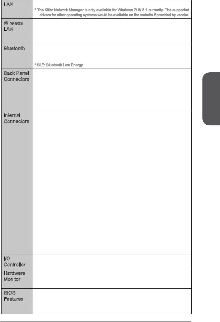
LAN 1x Killer E2205 Gigabit LAN controller*
* The Killer Network Manager is only available for Windows 7/ 8/ 8.1 currently. The supported
drivers for other operating systems would be available on the website if provided by vender.
Wireless
Wi-Fi/Bluetooth expansion module with Intel Dual Band Wireless-
LAN
AC 7260 chip.
-
to 867 Mbps speed.
Bluetooth Wi-Fi/Bluetooth expansion module with Intel Dual Band Wireless-
AC 7260 chip.
-
* BLE: Bluetooth Low Energy
Back Panel
1x PS/2 keyboard/ mouse combo port
Connectors
2x USB 2.0 ports
1x Clear CMOS button
1x LAN (RJ45) port
1x Optical S/PDIF OUT connector
5x OFC audio jacks
English
Internal
1x 24-pin ATX main power connector
Connectors
1x 8-pin ATX 12V power connector
1x 4-pin ATX 12V power connector
10x SATA 6Gb/s connectors
1x M.2 connector
1x SATA Express connector
2x USB 2.0 connectors (supports additional 4 USB 2.0 ports)
2x 4-pin CPU fan connectors
1x Front panel audio connector
2x System panel connectors
1x TPM module connector
1x Chassis Intrusion connector
9x V-Check connectorsts
1x Clear CMOS jumper
1x Power button
1x Reset button
1x OC Genie button
1x Multi-BIOS switch
1x OC Genie mode switch
1x Audio power switch
1x Slow mode booting switch
1x 2-Digit Debug Code LED
1x Wi-Fi/Bluetooth module connector
I/O
NUVOTON NCT6792 Controller Chip
Controller
Hardware
CPU/System temperature detection
Monitor
CPU/System fan speed detection
CPU/System fan speed control
BIOS
2x
Features
UEFI AMI BIOS
ACPI 5.0, PnP 1.0a, SM BIOS 2.7, DMI 2.0
Multi-language
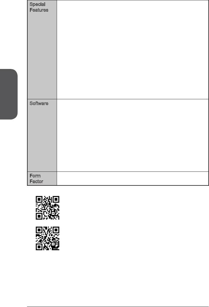
Special
Streaming Engine
Features
Audio Boost 2
Military Class 4
OC Genie 4
CLICK BIOS 4
NVIDIA SLI
AMD CrossFire
Easy Button
V-Check Points
Clear CMOS Button
Total Fan Control
Gaming Device Port
Super Charger
Smart Utilities
Wi-Fi
English
Bluetooth
Command Center
ECO Center
Software Drivers
MSI
- Command Center
- Live Update 6
- Smart Utilities
- Super Charger
- Fast Boot
- MB Gaming APP
- ECO Center
XSplit Gamecaster
Sound Blaster Cinema2
Norton Internet Security Solution
Intel Extreme Tuning Utility
Form
EATX Form Factor
Factor
For the latest information about CPU, please visit
http://www.msi.com/cpu-support/
For more information on compatible components, please visit
http://www.msi.com/test-report/
En-4
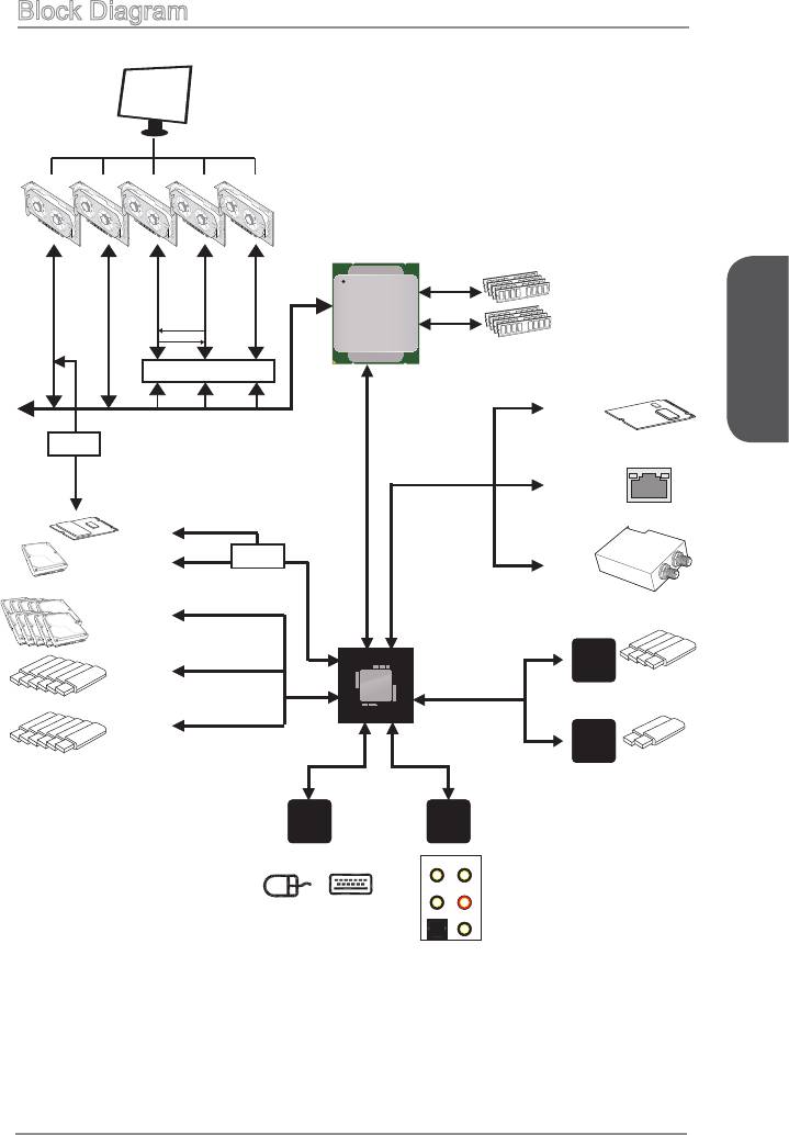
Block Diagram
PCI Express 3.0 x8
PCI Express 3.0 x16
PCI Express 3.0 x8
PCI Express 3.0 x8
PCI Express 3.0 x16
4 Channel DDR4 Memory
Haswell-E
Processor
LGA2011-3 CPU
Switch
Switch
English
x1
Streaming
Engine
PCI Express Bus (for 40 lanes CPU only)
Switch
x4
PCI Express Bus
x1
Killer E2205
Gigabit LAN
x2
DMI 2.0
1 x M.2
OR
Switch
x1
1 x SATA Express
PCI Express Bus
Wi-Fi /
Bluetooth
10 x SATA 6Gb/s
(2 ports reserved for SATA Express)
x1
X99 PCH
VIA
VL805
6 x USB 3.0
4 x USB 3.0
PCI Express Bus
6 x USB 2.0
x2
ASMEDIA
ASM1042AE
LPC Bus
2 x USB 3.0
NV6792
Realtek
Super I/O
ALC1150
PS/2 Mouse / Keyboard
CS-Out
Line-In/ SS-Out
Line-OutRS-Out
S/PDIF-Out
MIC
En-5
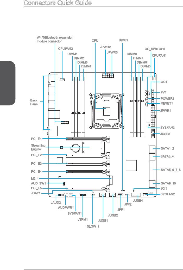
Connectors Quick Guide
Wi-Fi/Bluetooth expansion
BIOS1
module connector
CPU
JPWR2
CPUFAN2
OC_SWITCH6
DIMM1
DIMM8
CPUFAN1
DIMM2
DIMM7
DIMM6
DIMM4
DIMM5
English
OC1
FV1
POWER1
Back
Panel
RESET1
JPWR1
PCI_E1
Streaming
Engine
SATA1_2
PCI_E2
SATA5_6_7_8
PCI_E4
M2_1
AUD_SW1
SATA9_10
PCI_E5
JCI1
JBAT1
SYSFAN2
JUSB4
JAUD2
JFP2
AUDPWR1
JFP1
SYSFAN1
JUSB2
JTPM1
JUSB1
SLOW_1
En-6

Connectors Reference Guide
Port Name Port Type Page
AUDPWR1 Direct Audio Power Connector En-26
Back panel En-8
DIMM1~8 Memory slots En-14
FV1 V-Check Connectors En-28
JAUD2 Front Panel Audio Connector En-26
English
JCI1 Chassis Intrusion Connector En-25
JTPM1 TPM Module Connector En-27
JUSB1~2 USB 2.0 Expansion Connectors En-25
M2_1 M.2 Port En-21
OC1 OC Genie Button En-29
PCI_E1~5 PCIe Expansion Slots En-19
SATA1~10 SATA Connectors En-20
SATA_EX1 SATA Express Connector En-21
En-7
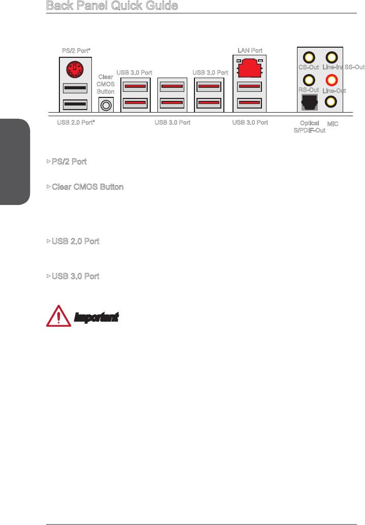
Back Panel Quick Guide
PS/2 Port*
LAN Port
CS-Out
Line-In/ SS-Out
Clear
CMOS
Button
RS-Out
Line-Out
USB 2.0 Port*
Optical
MIC
S/PDIF-Out
* Gaming Device Port
English
PS/2 Port
®
®
A PS/2
DIN connector is for a PS/2
mouse/keyboard.
Clear CMOS Button
There is CMOS RAM present on board that is powered by an external battery to store
the operating system (OS) every time it is turned on. If you wish to clear the system
USB 2.0 Port
The USB 2.0 port is for attaching USB 2.0 devices such as keyboard, mouse, or other
USB 2.0-compatible devices.
rate up to 5 Gbit/s (SuperSpeed).
Important
En-8
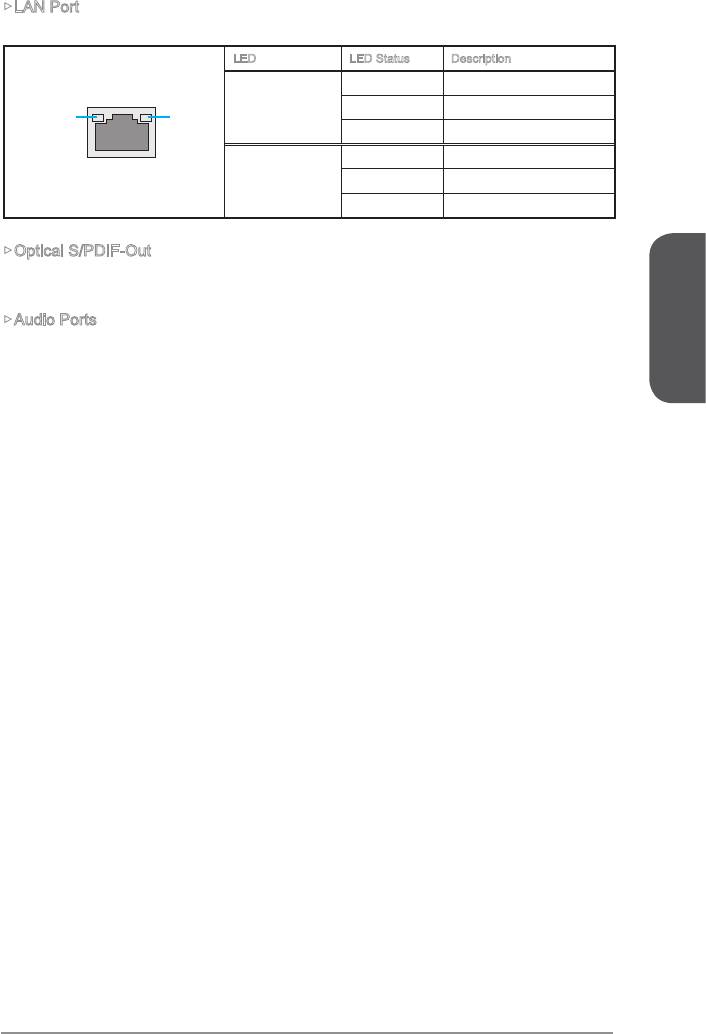
LAN Port
The standard RJ-45 LAN jack is for connecting to a Local Area Network (LAN).
LED LED Status Description
No link
Link/ Activity LED
Yellow Linked
LINK/ACT
SPEED
LED
LED
Blinking Data activity
10 Mbps connection
Speed LED
Green 100 Mbps connection
Orange 1 Gbps connection
Optical S/PDIF-Out
Audio Ports
These connectors are used for audio devices.
English
Line-In/ SS-Out: Line-In is used for connecting external audio outputting devic-
es. SS-Out is side surround line out in 7.1 channel mode.
Line out: Used as a connector for speakers or headphone.
Mic: Used as a connector for a microphone.
RS-Out: Rear surround sound line out in 4/ 5.1/ 7.1 channel mode.
CS-Out: Center/ subwoofer line out in 5.1/ 7.1 channel mode.
En-9
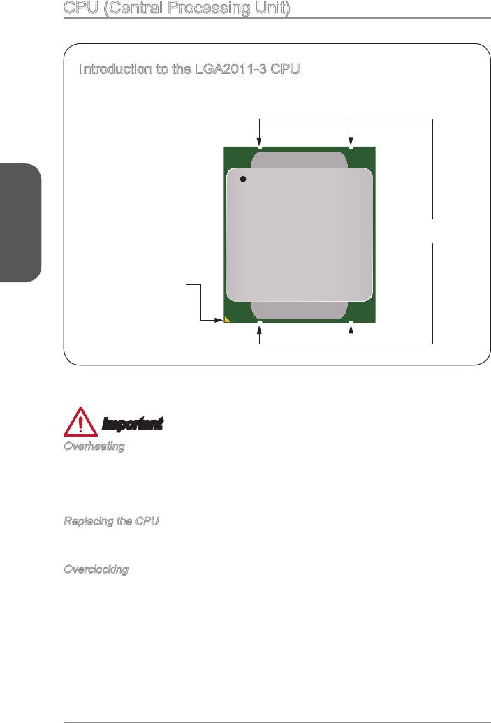
CPU (Central Processing Unit)
The surface of the
alignment keys and a
yellow triangle to assist in
correctly lining up the CPU
for motherboard placement.
The yellow triangle is the
Pin 1 indicator.
English
Alignment Key
Yellow triangle is the
Pin 1 indicator
Important
Overheating
Overheating can seriously damage the CPU and motherboard. Always make sure the
cooling fans work properly to protect the CPU from overheating. Be sure to apply an
even layer of thermal paste (or thermal tape) between the CPU and the heatsink to
enhance heat dissipation.
Replacing the CPU
power supply’s power cord to ensure the safety of the CPU.
Overclocking
This motherboard is designed to support overclocking. Before attempting to overclock,
please make sure that all other system components can tolerate overclocking. Any
guarantee the damages or risks caused by inadequate operation beyond product
En-10
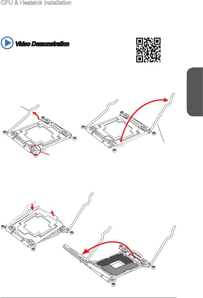
When installing a CPU, always remember to install a CPU heatsink. A CPU heatsink
is necessary to prevent overheating and maintain system stability. Follow the steps
below to ensure correct CPU and heatsink installation. Wrong installation can damage
both the CPU and the motherboard.
Video Demonstration
http://youtu.be/WPhyn2C5mgs
1. Open hinge lever. You can identify the hinge lever as below shown, it with a
interlocking feature on the other end.
2. Open active lever.
English
Hinge lever
Active lever
Interlock
4. Grasp the tab, only it has risen away from the socket, open load plate to full open
position.
En-11
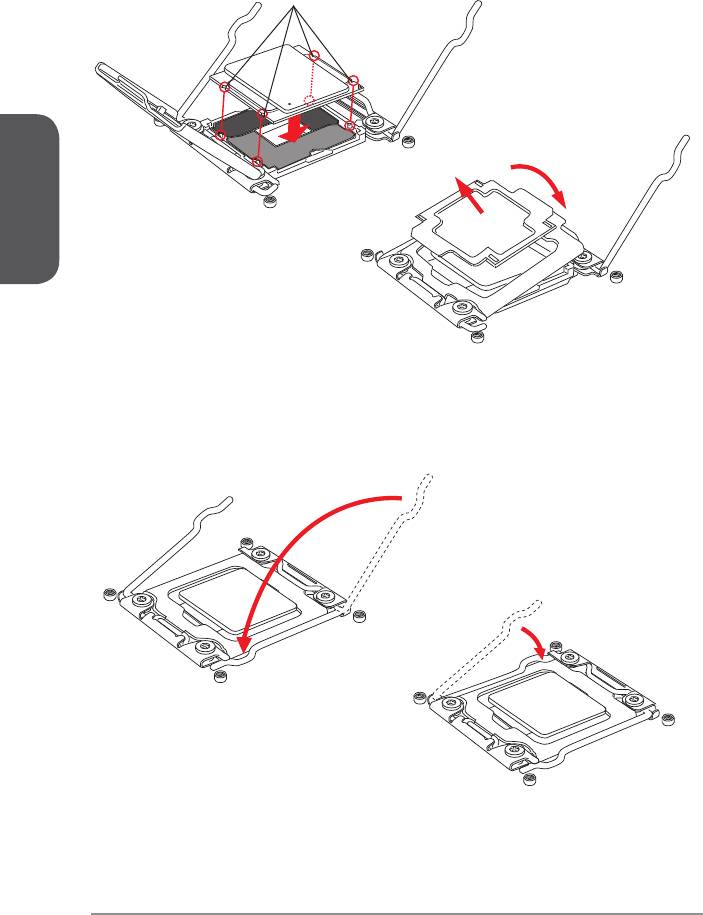
the metal contacts facing downward. The alignment keys on the CPU will line up
6. Carefully close the load plate and remove the plastic protective cap.
Alignment Key
English
7. Close the active lever with a smooth uniform motion and latch to the socket.
8. Close the hinge lever with a smooth uniform motion and latch to the socket.
En-12
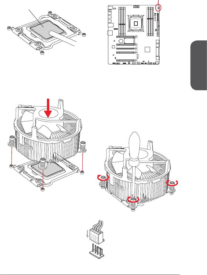
9. Evenly spread a thin layer of thermal paste (or thermal tape) on the top of the
CPU. This will help in heat dissipation and prevent CPU overheating.
10. Locate the CPU fan connector on the motherboard.
CPUFAN1
Thermal paste
English
11. Place the heatsink on the motherboard with the fan’s wires facing towards the fan
connector and the screws matching the holes on the socket.
12. Using a screwdriver tighten the four captive screws (9 inch-pounds).
to the CPU fan connector on the
motherboard.
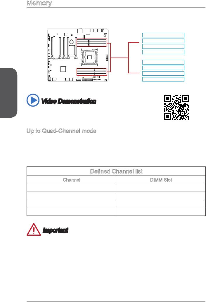
Memory
These DIMM slots are used for installing memory modules.
DIMM1
DIMM2
DIMM4
DIMM8
DIMM7
DIMM6
DIMM5
English
Video Demonstration
Watch the video to learn how to install memory.
Up to Quad-Channel mode
This motherboard supports up to four memory channels. Two DIMM slots provide a
single channel. The memory modules can transmit and receive data with four data bus
channels simultaneously to enhance system performance. Please refer the following
tables for more details.
Channel DIMM Slot
Channel A DIMM1, DIMM2
Channel B
Channel C DIMM5, DIMM6
Channel D DIMM7, DIMM8
Important
standard is not backward compatible. Always install DDR4 memory modules in
DDR4 DIMM slots.
Due to chipset resource usage, the system will only detect up to 127+ GB of
memory (not full 128 GB) when all DIMM slots have 16GB memory modules
installed.
En-14
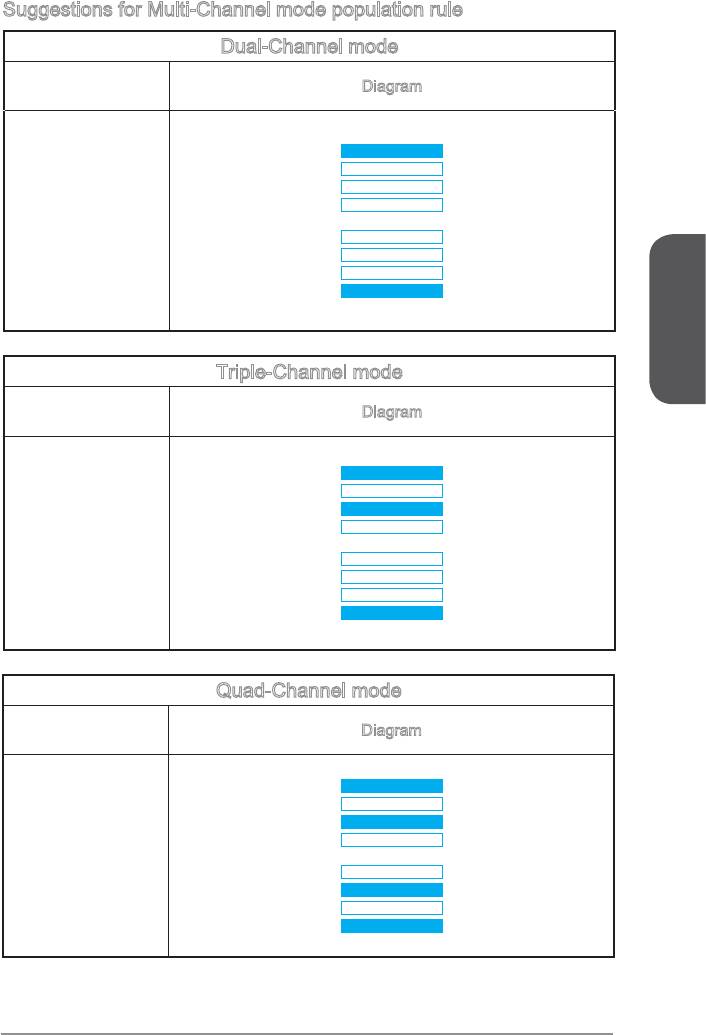
Suggestions for Multi-Channel mode population rule
Dual-Channel mode
Installed DIMMs
Diagram
(2 memory modules)
DIMM1
DIMM2
DIMM4
DIMM1, DIMM5
DIMM8
DIMM7
DIMM6
DIMM5
English
Triple-Channel mode
Installed DIMMs
Diagram
DIMM1
DIMM2
DIMM4
DIMM8
DIMM7
DIMM6
DIMM5
Quad-Channel mode
Installed DIMMs
Diagram
(4 memory modules)
DIMM1
DIMM2
DIMM4
DIMM5, DIMM7
DIMM8
DIMM7
DIMM6
DIMM5
En-15
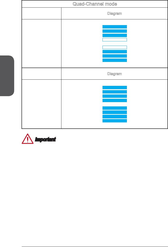
Quad-Channel mode
Installed DIMMs
Diagram
(6 memory modules)
DIMM1
DIMM2
DIMM4
DIMM5, DIMM6, DIMM7
DIMM8
DIMM7
DIMM6
DIMM5
English
Installed DIMMs
Diagram
(8 memory modules)
DIMM1
DIMM2
DIMM1, DIMM2,
DIMM4
DIMM5, DIMM6,
DIMM7, DIMM8
DIMM8
DIMM7
DIMM6
DIMM5
Important
To ensure system stability for Dual/ Triple/ Quad channel mode, memory modules
must be of the same type, number and density. And for every channel, the odd
En-16
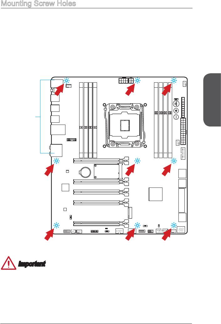
Mounting Screw Holes
for an motherboard on the mounting plate in your computer case. If there is an
I/O back plate that came with the computer case, please replace it with the I/O
backplate that came with the motherboard package. The I/O backplate should snap
easily into the computer case without the need for any screws. Align the mounting
plate’s mounting stands with the screw holes on the motherboard and secure the
motherboard with the screws provided with your computer case. The locations of the
screw holes on the motherboard are shown below. For more information, please refer
to the manual that came with the computer case.
holes on the I/O backplate.
case. They should line up with the
toward the rear of the computer
The I/O ports should be facing
English
Important
To prevent damage to the motherboard, any contact between the motherboard
circuitry and the computer case, except for the mounting stands, is prohibited.
Please make sure there are no loose metal components on the motherboard or
within the computer case that may cause a short circuit of the motherboard.
En-17
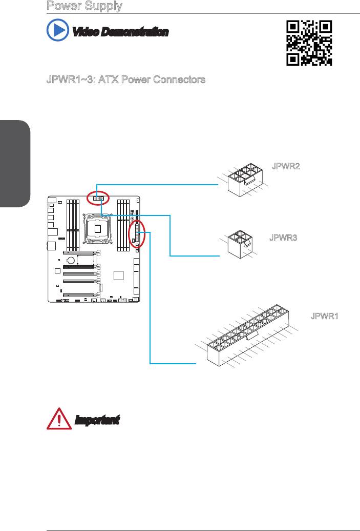
Power Supply
Video Demonstration
Watch the video to learn how to install power supply connectors.
These connectors allow you to connect an ATX power supply. To connect the ATX
cable into the connector. If done correctly, the clip on the power cable should be
hooked on the motherboard’s power connector.
English
13.+3.3V
En-18
1.+3.3
3.
Ground
7.+12V
12.+3.3V
11. +12 V
10.+12V
9.5VSB
8.PWR OK
7.Ground
6.+5V
5.Ground
4.+5V
3.Ground
2.+3.3V
24.Ground
23.+5V
V
22.+5V
21.+5V
20.Res
19.Ground
18.Ground
17.Ground
16.PS-ON#
15.Ground
14.-12V
1.
5.+12V
Ground
8.+12V
4
.Ground
2.Ground
6.+12V
JPWR1
1
3.+12V
.Ground
4.+12V
2
JPWR2
.Ground
Important
Make sure that all the power cables are securely connected to a proper ATX power
supply to ensure stable operation of the motherboard.
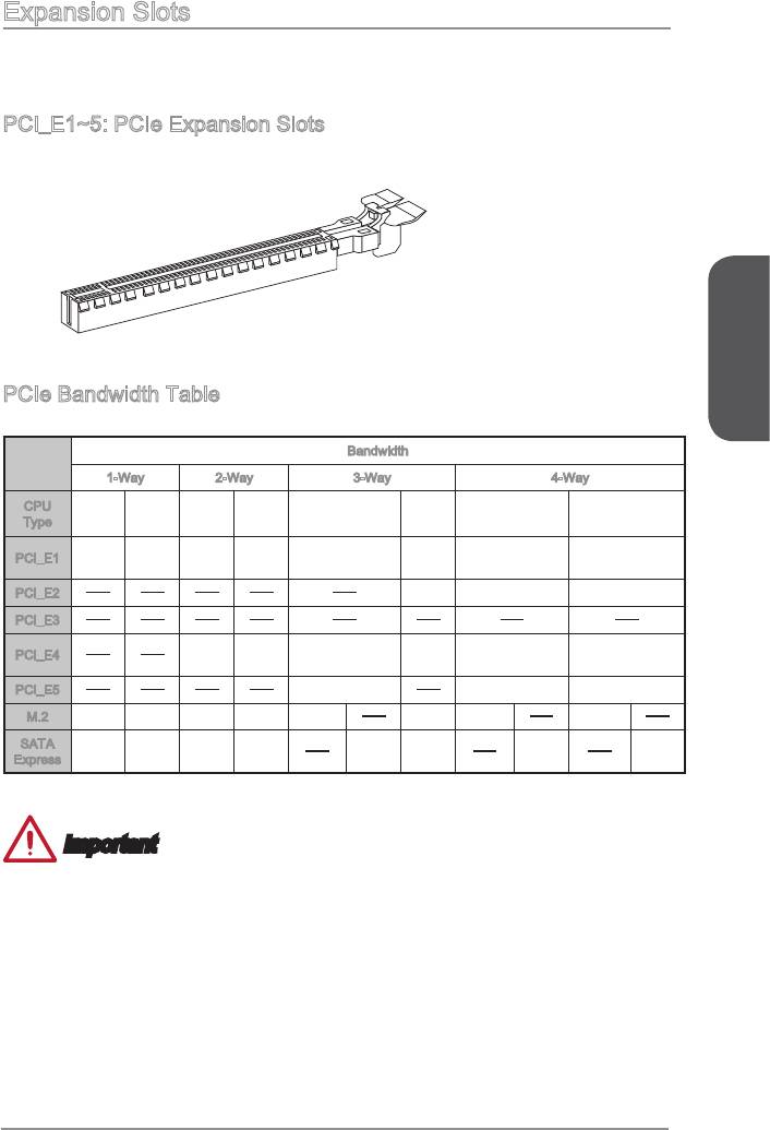
Expansion Slots
This motherboard contains numerous slots for expansion cards, such as discrete
graphics or audio cards.
PCI_E1~5: PCIe Expansion Slots
The PCIe slot supports the PCIe interface expansion card.
English
PCIe Bandwidth Table
Bandwidth
1-Way 2-Way 4-Way
CPU
40
28
40
28
40
28
40
28
Type
lanes
lanes
lanes
lanes
lanes
lanes
lanes
lanes
3.0
3.0
3.0
3.0
PCI_E1
3.0 x16 3.0 x8 3.0 x8 3.0 x8
x16
x16
x16
x16
PCI_E2
3.0 x8 3.0 x8 3.0 x8
3.0
PCI_E4
3.0 x8 3.0 x16 3.0 x8 3.0 x16 3.0 x8
x16
PCI_E5
3.0 x8 3.0 x8 3.0 x4
M.2
3.0 x4 3.0 x4 3.0 x4 3.0 x4 2.0 x2*
3.0 x4 2.0 x2* 2.0 x2*
SATA
2.0 x2 2.0 x2 2.0 x2 2.0 x2
2.0 x2 2.0 x2 2.0 x2 2.0 x2
Express
* When installing the M.2 PCIe interface module, please set the “M.2 PCH Strap” for [M.2 PCIE] in BIOS.
Important
®
™
28 lanes CPU does not support 4-Way NVIDIA
SLI
Technology.
For a single PCIe x16 expansion card installation with optimum performance, using
the PCI_E1 slot is recommended.
unplug the power supply power cable from the power outlet. Read the expansion
card’s documentation to check for any necessary additional hardware or software
changes.
En-19
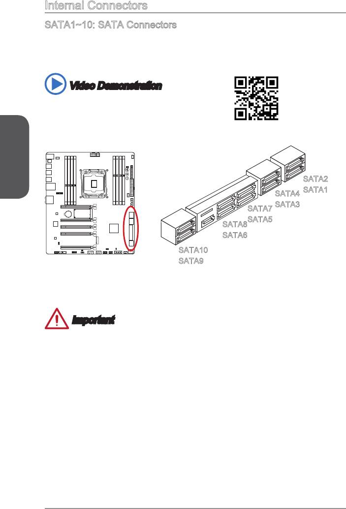
Internal Connectors
SATA1~10: SATA Connectors
This connector is a high-speed SATA interface port. Each connector can connect to
one SATA device. SATA devices include disk drives (HDD), solid state drives (SSD),
and optical drives (CD/ DVD/ Blu-Ray).
Video Demonstration
Watch the video to learn how to Install SATA HDD.
http://youtu.be/RZsMpqxythc
English
SATA2
SATA1
SATA4
SATA7
SATA5
SATA8
SATA6
SATA10
SATA9
SATA1~6 support RAID 0, RAID 1, RAID 5 and RAID 10.
SATA7~10 ports only support IDE mode and AHCI mode.
Important
The SATA5 and SATA6 ports will be unavailable when installing a M.2 SATA
interface module in the M.2 port.
Many SATA devices also need a power cable from the power supply. Such devices
include disk drives (HDD), solid state drives (SSD), and optical drives (CD / DVD /
Blu-Ray). Please refer to the device’s manual for further information.
Many computer cases also require that large SATA devices, such as HDDs, SSDs,
and optical drives, be screwed down into the case. Refer to the manual that came
with your computer case or your SATA device for further installation instructions.
Please do not fold the SATA cable at a 90-degree angle. Data loss may result
during transmission otherwise.
SATA cables have identical plugs on either sides of the cable. However, it is
saving purposes.
En-20
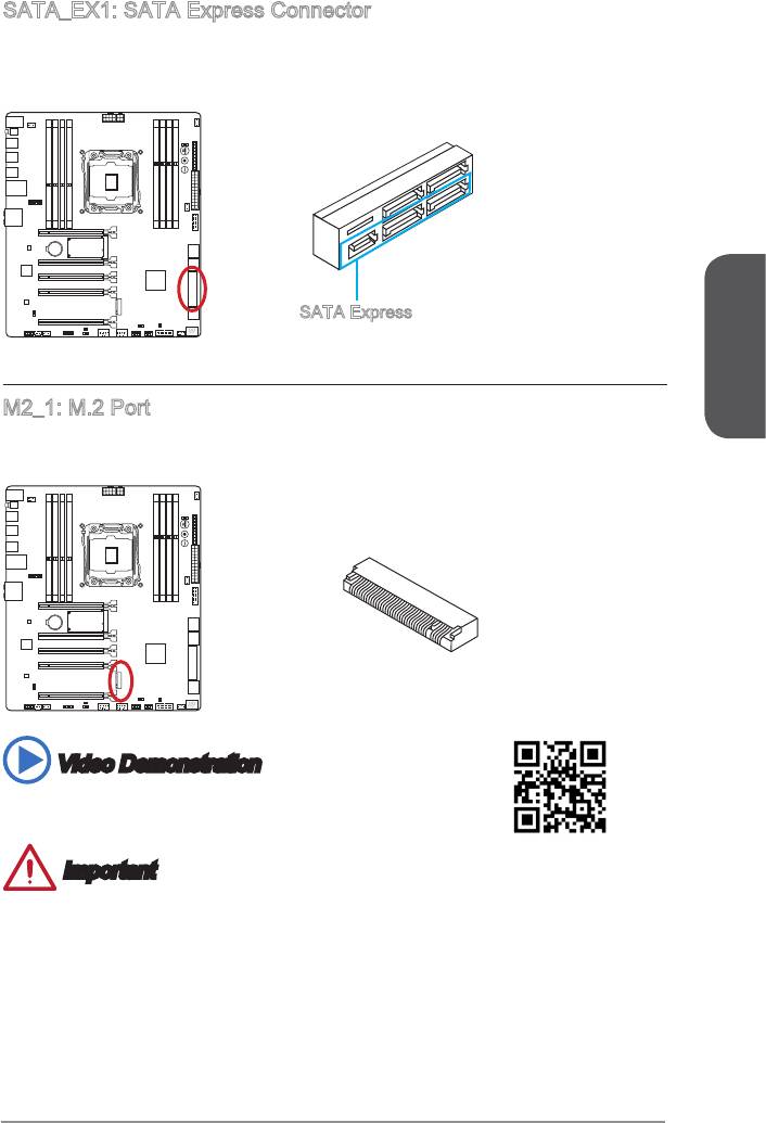
SATA_EX1: SATA Express Connector
The SATA Express, a new high performance storage interface, supports to connect 1
SATA Express device with up to 10 Gb/s transfer rate. Connects the SATA Express
SATA Express
English
M2_1: M.2 Port
The M.2 port supports either M.2 SATA 6Gb/s module or M.2 PCIe module.
Video Demonstration
Watch the video to learn how to install M.2 module.
http://youtu.be/JCTFABytrYA
Important
The SATA Express port/ SATA5~6 ports will be unavailable when installing the M.2
SATA interface module in the M.2 port.
Intel RST does not support PCIe M.2 SSD with Legacy ROM.
M.2 PCIe interface does not support RAID 0, RAID1, RAID 5 and RAID 10.
before installing or removing the M.2 module.
En-21
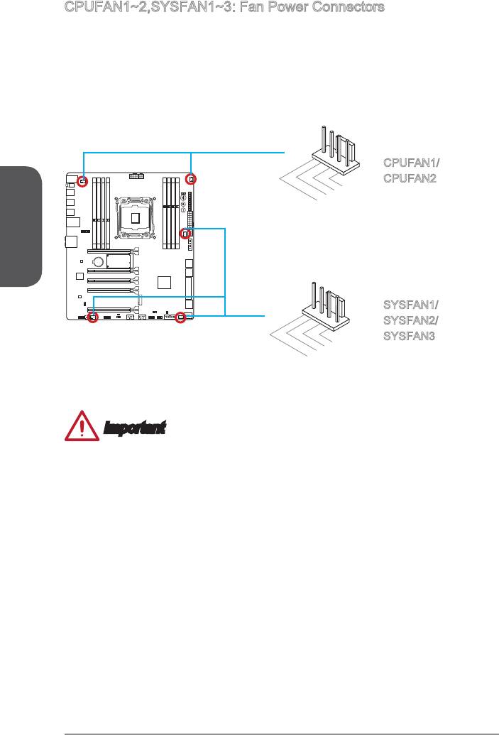
The fan power connectors support system cooling fans with +12V. If the motherboard
has a System Hardware Monitor chipset on-board, you must use a specially designed
fan with a speed sensor to take advantage of the CPU fan control. Remember to
connect all system fans. Some system fans may not connect to the motherboard and
will instead connect to the power supply directly. A system fan can be plugged into
any available system fan connector.
English
1.Ground
2.Speed Contro
En-22
l
1.Ground
2.+12V
3.Sense
4.Speed Contro
3.Sense
4.NC
l
CPUFAN1/
CPUFAN2
SYSFAN1/
SYSFAN2/
Important
recommended CPU heatsink.
These connectors support Smart Fan Control with liner mode. The Command
Center utility can be installed to automatically control the fan speeds according to
the CPU’s and system’s temperature.
If there are not enough ports on the motherboard to connect all system fans,
adapters are available to connect a fan directly to a power supply.
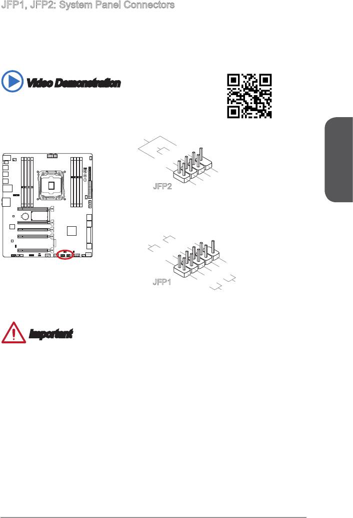
JFP1, JFP2: System Panel Connectors
These connectors connect to the front panel switches and LEDs. The JFP1 connector
®
is compliant with the Intel
Front Panel I/O Connectivity Design Guide. When
installing the front panel connectors, please use the optional M-Connector to simplify
installation. Plug all the wires from the computer case into the M-Connector and then
plug the M-Connector into the motherboard.
Video Demonstration
Watch the video to learn how to Install front panel connectors.
http://youtu.be/DPELIdVNZUI
English
10.No Pin
5.-
3.-
1.+
Reset S
witch
HDD LE
P
D
ower Switch
P
3.Suspend LE
1.Ground
ower LED
8.-
6.+
4.-
2.+
9.Reserved
7.+
JFP1
D
5.Power LE
D
8.+
Buzzer
6.-
4.+
2.-
7.No Pin
S
peaker
JFP2
Important
On the connectors coming from the case, pins marked by small triangles are
positive wires. Please use the diagrams above and the writing on the optional
M-Connectors to determine correct connector orientation and placement.
The majority of the computer case’s front panel connectors will primarily be plugged
into JFP1.
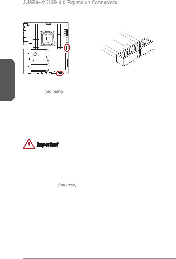
transfer rates up to 5Gbits/s (SuperSpeed).
20.No Pin
19.Power
18.USB3_RX_DN
17.USB3_RX_DP
16.Ground
15.USB3_TX_C_DN
14.USB3_TX_C_DP
13.Ground
12.USB2.0 -
1.Power
2.USB3_RX_DN
3.USB3_RX_DP
4.Ground
5.
6.USB3_TX_C_DP
USB3_TX_C_DN
7.Ground
8. -USB2.0
9. +USB2.0
10.Ground
English
En-24
11
. +
USB2.0
(red mark) connector supports MSI’s new Super-Charger technology
which provides quicker USB charging of your smartphone or other USB-powered
devices. To enable this feature, please install the MSI Super-Charger application
connector will convert data channels to extra power channels to quickly charge your
connected device. Please note that when the Super-Charger application is turned on,
Important
Note that the VCC and GND pins must be connected correctly to avoid possible
damage.
Please only connect one device per USB port to ensure stable charging.
Super-Charger Technology is only available on select MSI motherboard models.
Please refer to the MSI website to check if your motherboard has Super-Charger
technology.
(red mark)
We recommend that don’t disconnect the device when you charge it in S1 state.
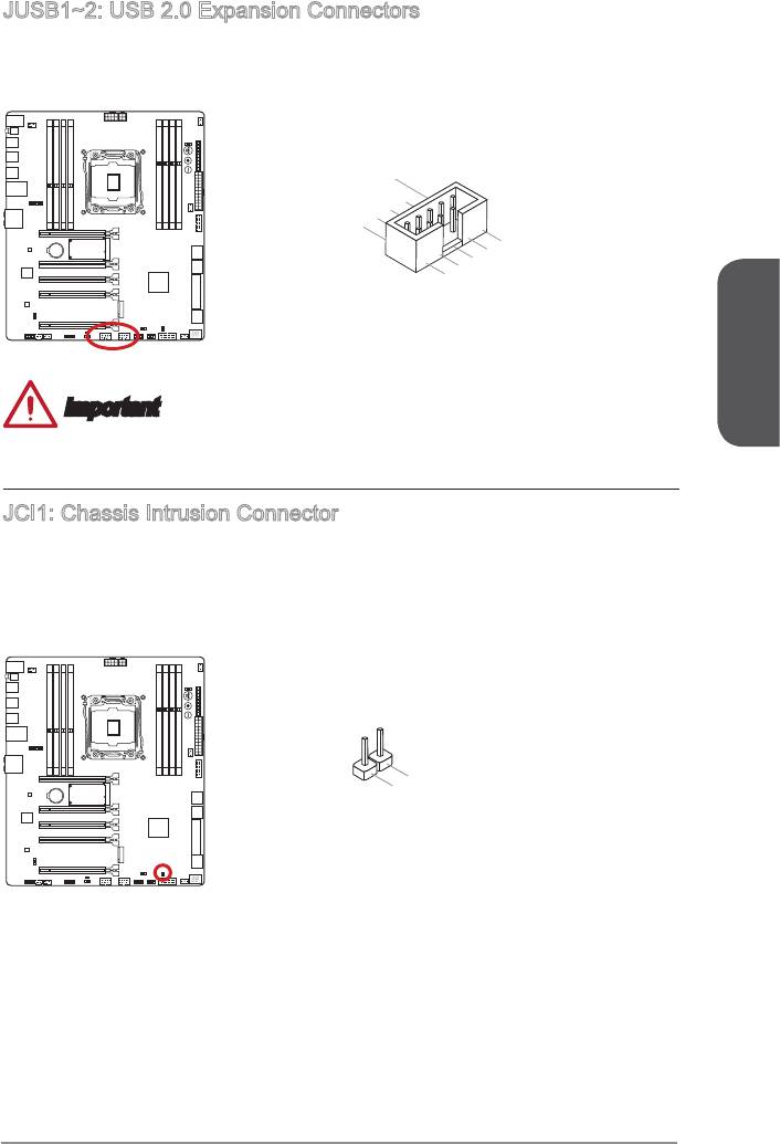
JUSB1~2: USB 2.0 Expansion Connectors
This connector is designed for connecting high-speed USB peripherals such as USB
English
En-25
1
0
8
.
.
N
6
G
C
.
U
r
4
o
.
S
u
U
S
B
n
B
1
d
+
1
-
2
.
V
C
C
1
.
V
C
C
3
.
U
S
B
0
-
7
5
.
G
.
U
r
o
S
u
B
n
0
+
d
9
.
N
o
P
in
Important
Note that the VCC and GND pins must be connected correctly to avoid possible
damage.
JCI1: Chassis Intrusion Connector
This connector connects to the chassis intrusion switch cable. If the computer case is
opened, the chassis intrusion mechanism will be activated. The system will record this
enter the BIOS utility and clear the record.
1
.
2
G
.
C
r
o
I
N
u
n
T
d
R
U
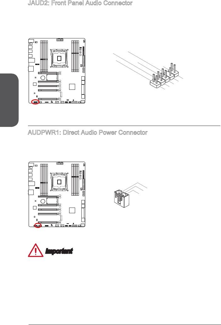
JAUD2: Front Panel Audio Connector
This connector allows you to connect the front audio panel located on your computer
®
case. This connector is compliant with the Intel
Front Panel I/O Connectivity Design
Guide.
English
3.MIC R
1.MIC L
En-26
10.Head
Phone Detection
5.Head Phone
R
7.SENSE_SEN
D
9.Head Phone
L
8.No Pin
6.MIC Detection
4.NC
2
.Ground
AUDPWR1: Direct Audio Power Connector
This connector is used to provide direct power to back panel audio ports. The direct
audio power can provide the better audio quality. Please connect this connector with a
power supply by an audio power adapter.
3.Ground
2.+12V_AUD
1.Ground
Important
After connecting the direct power to this connector, please note that you have to
enable the “Direct Audio Power” by adjusting the audio power switch (AUD_SW1).
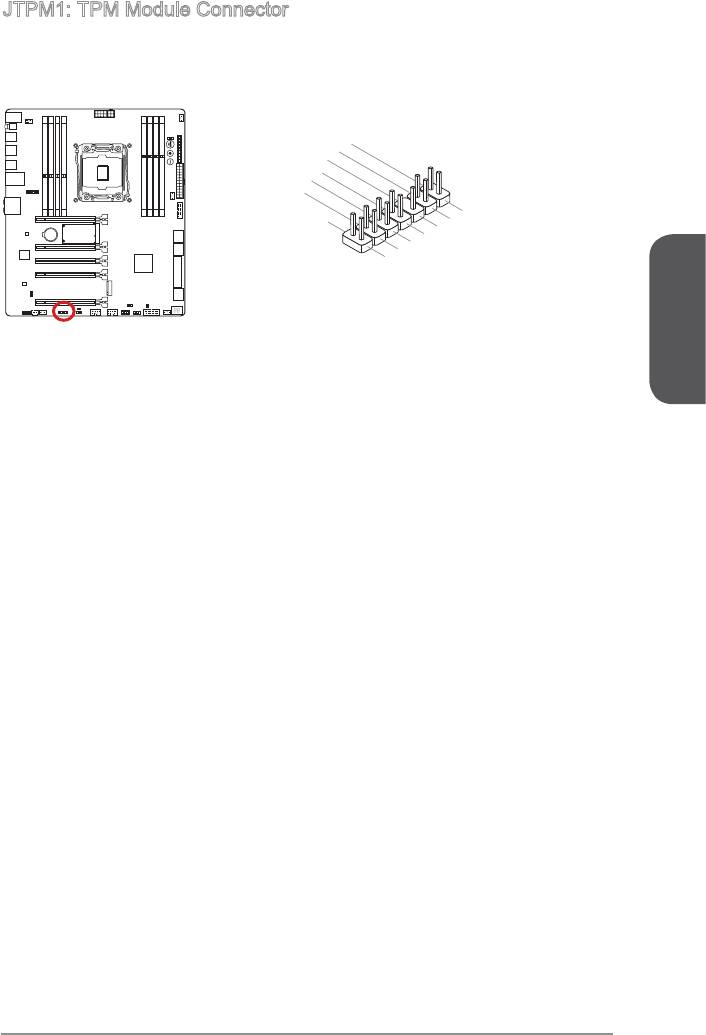
JTPM1: TPM Module Connector
This connector connects to a TPM (Trusted Platform Module). Please refer to the TPM
security platform manual for more details and usages.
14.Ground
12.Ground
10.No Pin
8.5V Power
6.Serial IRQ
4.3.3V Power
2.3V Standby power
13.LPC Frame
11.LPC address & data pin3
9.LPC address & data pin2
7.LPC address & data pin1
5.LPC address & data pin0
3.LPC Reset
1.LPC Clock
English
En-27
Voltage Checkpoints
These voltage checkpoints are used to measure the current system voltages. A
multimeter (not included) will be required to check voltages.
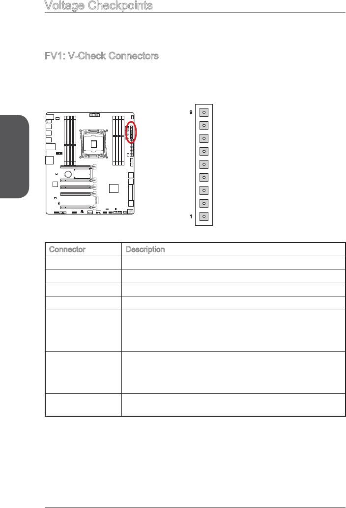
FV1: V-Check Connectors
To check the voltage, please use the optional voltage checkpoint cables included in
the motherboard package. Attach the positive lead of the multimeter to the voltage
checkpoint cable and the negative lead to the ground connector.
9
GND
GND
English
GND
CORE
VPP01
DDR01
1
VCCIN
Connector Description
GND (pin 7~9) Ground
CORE (pin 6) CPU core power.
VPP VR power source for channel C/ D DDR memory.
VPP01 (pin 4) VPP VR power source for channel A/ B DDR memory.
Memory voltage for channel C/ D. The DDR memory voltage
is the voltage supplied to the DDR memory modules on the
motherboard. Lower memory timings may require higher
voltages to maintain system stability.
DDR01 (pin 2) Memory voltage for channel A/ B. The DDR memory voltage
is the voltage supplied to the DDR memory modules on the
motherboard. Lower memory timings may require higher
voltages to maintain system stability.
VCCIN (pin1) The CPU VCCIN voltage is the CPU power source that is
shared with components of the CPU.
En-28
Button
The motherboard has numerous on-board buttons to control various functions. This
section will explain how to change your motherboard’s functions through the use of
these on-board buttons.
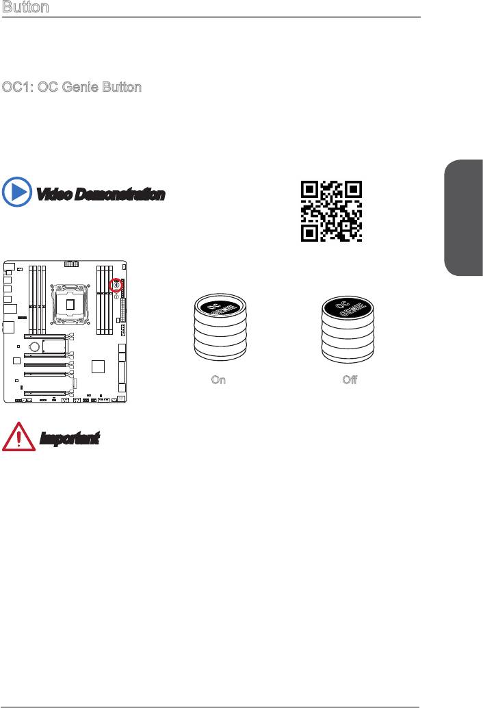
OC1: OC Genie Button
This button is used to automatically overclock the system. To enable OC Genie,
the processor will be automatically overclock for optimal performance. To disable
Video Demonstration
Watch the video to learn how to use the OC Genie button.
English
OC
OC
GENIE
GENIE
On
Important
This motherboard provides two ways to enable OC Genie: press the physical OC
Genie button on the motherboard, or click the virtual OC Genie button in BIOS. You
can specify how OC Genie to be enabled by using the "OC Genie Function Control"
item in BIOS.
use the OC Genie function.
We do not guarantee the OC Genie overclocking range or the damages/risks
caused by overclocking behavior.
It is possible to disable the OC Genie function in the BIOS setup. Please refer to the
BIOS.
The usage of OC Genie is at the user’s own risk. Overclocking is never guaranteed
by MSI.
To ensure successfully OC Genie usage, MSI components are recommended.
En-29
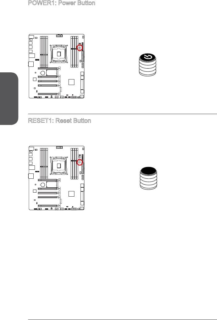
POWER1: Power Button
English
RESET1: Reset Button
This reset button is used to reset the system. Press the button to reset the system.
Reset
Jumper
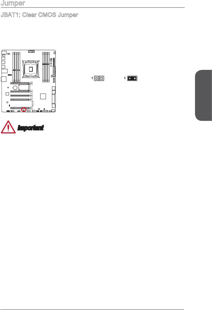
JBAT1: Clear CMOS Jumper
There is CMOS RAM onboard that is external powered from a battery located on the
automatically boot into the operating system (OS) every time it is turned on. If you
1 1
Keep Data Clear Data
English
Important
Afterwards, open the jumper . Do not clear the CMOS RAM while the system is on
because it will damage the motherboard.
Switch
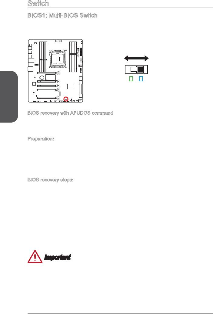
BIOS1: Multi-BIOS Switch
This motherboard has two built-in BIOS ROMs (Labeled A and B, default BIOS ROM
is A). If one is crashed, you can shift to the other for booting by sliding the switch.
BIOS B
BIOS A
Green LED
Blue LED
English
BIOS recovery with AFUDOS command
When BIOS updating fails or causes the computer non-bootable, you can recover the
failed BIOS by the steps below.
Preparation:
BIOS recovery steps:
2. Set the Multi-BIOS switch to the functional BIOS ROM.
5. Set the Multi-BIOS switch to the failed BIOS ROM.
Important
Do not use the Multi-BIOS switch when system is booting up.
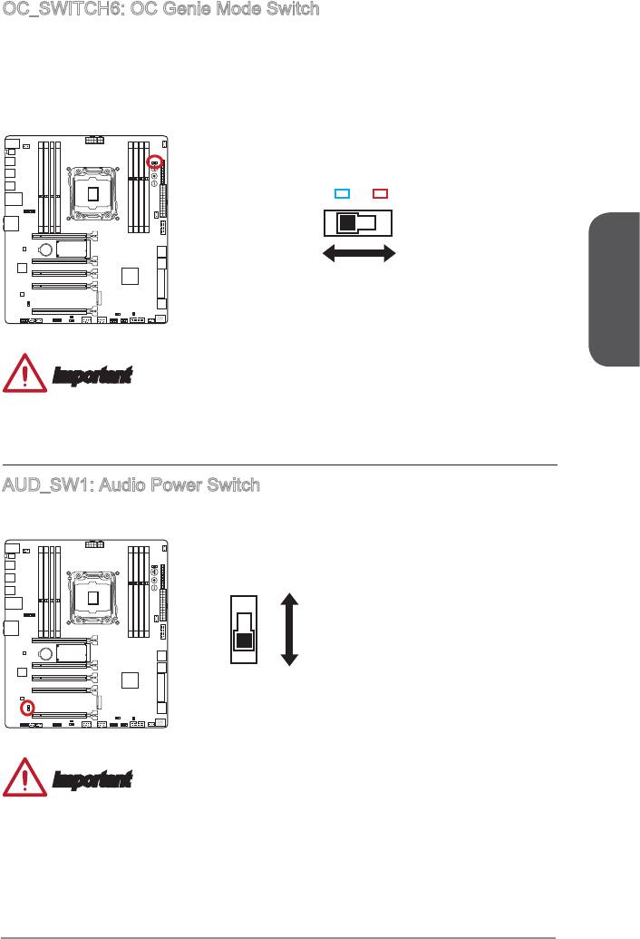
OC_SWITCH6: OC Genie Mode Switch
This swtich provides two overclocking modes (Gear 1 and Gear 2) for OC Genie
operation. When you press the OC Genie button, the overclocking procedure will
be performed according to the setting of this switch. The Gear 1 Mode is the default
setting. The Gear 2 Mode allows the OC Genie function to overclock the CPU/ system
frequency higher then Gear 1 Mode.
Blue LED
Red LED
Gear 1
Gear 2
(Default)
English
Important
Gear 1 Mode: For normal users using original fan.
Gear 2 Mode: For OCers using better heat dissipation fan such as liquid cooling or
AUD_SW1: Audio Power Switch
Direct Power mode
Onboard Power mode
(Default)
Important
Before switching to "Direct Power mode", please make sure the “Direct Audio Power
Connector” (AUDPWR1) has been connected to the power supply.
Do not use the audio power switch while the system is on because it will damage
the motherboard.
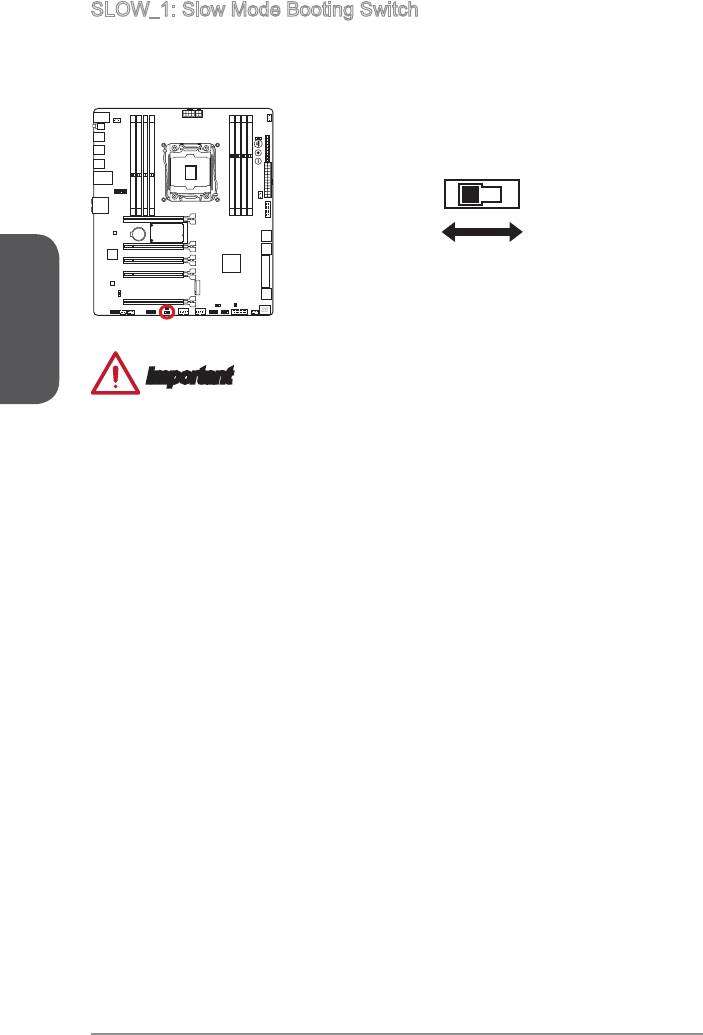
SLOW_1: Slow Mode Booting Switch
This switch is used for LN2 cooling solution, that provides the extreme overclocking
conditions, to boot at a stable processor frequency and to prevent the system from
crashing.
Normal
Enabled
(Default)
(Please enable this
English
swtich during BIOS
POST.)
Important
Users will try extreme low temperature overclocking at their own risks. The
overclocking results will vary according to the CPU version.
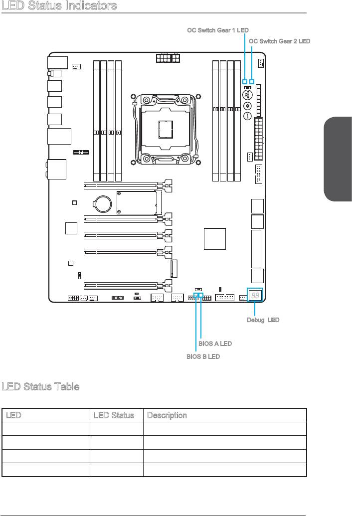
LED Status Indicators
OC Switch Gear 1 LED
OC Switch Gear 2 LED
English
Debug LED
BIOS A LED
BIOS B LED
LED Status Table
The following table describes the status of LED indicators.
LED LED Status Description
OC Switch Gear 1 Blue Gear 1 OC Genie mode
OC Switch Gear 2 Red Gear 2 OC Genie mode
BIOS B Green BIOS B in operation
BIOS A Blue BIOS A in operation
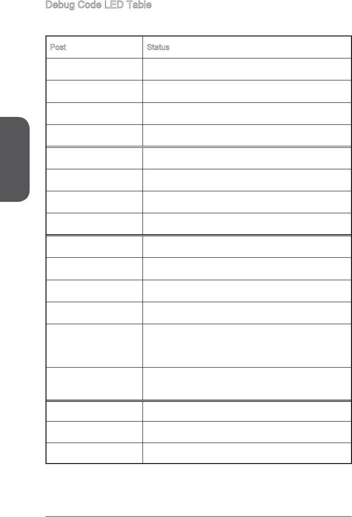
Debug Code LED Table
Please refer to the table below to get more information about the Debug Code LED
message.
Post Status
02,07
04,09
English
0B
69~6F,D1
70~77,D2
92~96,B5,D4
97,98,99,B2,D5~D7
Load Option ROM (VGA, RAID, parallel ports, serial
ports……)
9A~A7,B4
SCSI……)
A8,A9,AB Start of Setup. BIOS setup if needed/ requested.
AD/AE Ready To Boot event/Legacy Boot event
CPU temperature Fully boot
Drivers and Utilities
performance of the new computer you just built. MSI motherboard comes with a Driver
advantage of any special features we provide.
You can protect your computer from viruses by installing the bundled security
program. The bundle also includes a variety of powerful and creative utilities.
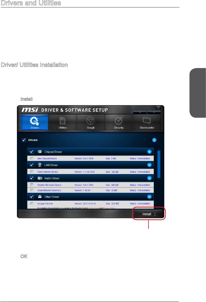
Driver/ Utilities Installation
Please follow the steps below to install drivers and utilities for your new computer.
1. Insert MSI Driver Disc into the optical drive. The installer will automatically appear
if autorun is enabled in OS.
2.
Click
Install button.
English
Click here
4.
you to restart.
5. Click
OK
6. Restart your computer.
You can also use the same method to install the utilities.
BIOS Setup
CLICK BIOS is developed by MSI that provides a graphical user interface for setting
parameters of BIOS by using the mouse and the keybord.
With the CLICK BIOS, users can change BIOS settings, monitor CPU temperature,
select the boot device priority and view system information such as the CPU name,
DRAM capacity, the OS version and the BIOS version. Users can import and export
parameters data for backup or sharing with friends.
Entering BIOS Setup
Power on the computer and the system will start the Power On Self Test (POST)
process. When the message below appears on the screen, press <DEL> key to enter
English
BIOS:
Press <Del> to run BIOS setup, or <F11> to run boot menu
If the message disappears before you respond and you still need to enter BIOS,
restart the system by turning the computer OFF then back ON or pressing the RESET
button. You may also restart the system by simultaneously pressing <Ctrl>, <Alt>, and
<Delete> keys.
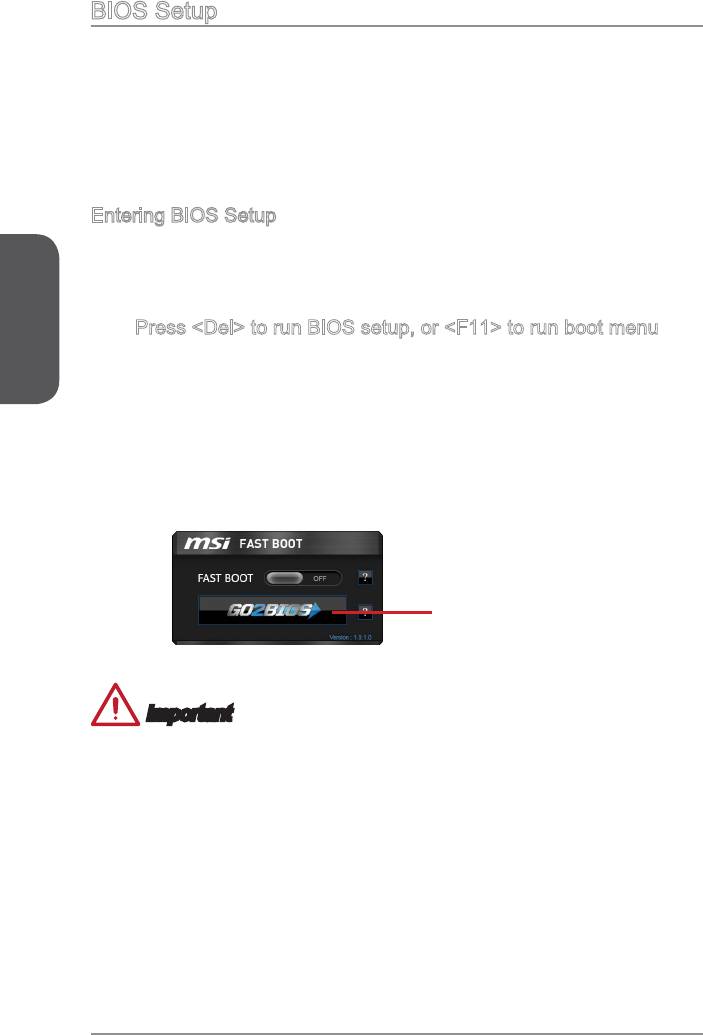
MSI additionally provides two methods to enter the BIOS setup. You can click the
“GO2BIOS” tab on “MSI Fast Boot” utility screen or press the physical “GO2BIOS"
button (optional) on the motherboard to enable the system going to BIOS setup
directly at next boot.
Click "GO2BIOS" tab on
"MSI Fast Boot" utility
screen.
Important
Please be sure to install the “MSI Fast Boot” utility before using it to enter the BIOS
setup.
The items under each BIOS category described in this chapter are under continuous
update for better system performance. Therefore, the description may be slightly
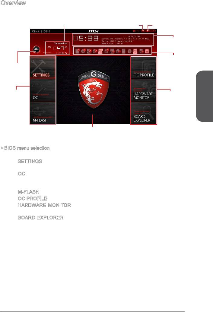
Overview
After entering BIOS, the following screen is displayed.
Temperature monitor
My Favorites
Language
System
information
Boot device
priority bar
Virtual OC
Genie Button
BIOS menu
BIOS menu
selection
selection
English
Menu display
BIOS menu selection
The following options are available:
SETTINGS - Uses this menu to specify the parameters for chipset and boot
devices.
OC - This menu contains the frequency and voltage adjustments. Increasing
the frequency can get better performance, however high frequency and heat
can cause instability, we do not recommend general users to overclock.
M-FLASH
OC PROFILE
HARDWARE MONITOR - This menu is used to set the speeds of fans and
monitor voltages of system.
BOARD EXPLORER - It provides the information of the installed devices on
the motherboard.
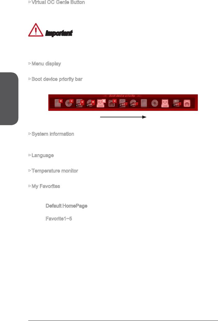
Virtual OC Genie Button
Enables or disables the OC Genie function by clicking on this button. When enabled,
this button will be light. Enabling OC Genie function can automatically overclock with
Important
not to load defaults after enabling the OC Genie function.
Menu display
Boot device priority bar
English
You can move the device icons to change the boot priority.
High priority Low priority
System information
Shows the time, date, CPU name, CPU frequency, DRAM frequency, DRAM capacity
and the BIOS version.
Language
Allows you to select the language of the BIOS setup.
Temperature monitor
Shows the temperatures of the processor and the motherboard.
My Favorites
Allows you to create your personal BIOS menu where you can save and access your
favorite/ frequently-used BIOS setting items.
Default HomePage - Allows you to select a BIOS menu (e.g. Settings, OC...,etc)
as the BIOS home page.
Favorite1~5 - Allows you to add the frequently-used/ favorite BIOS setting items
in one page.
En-40
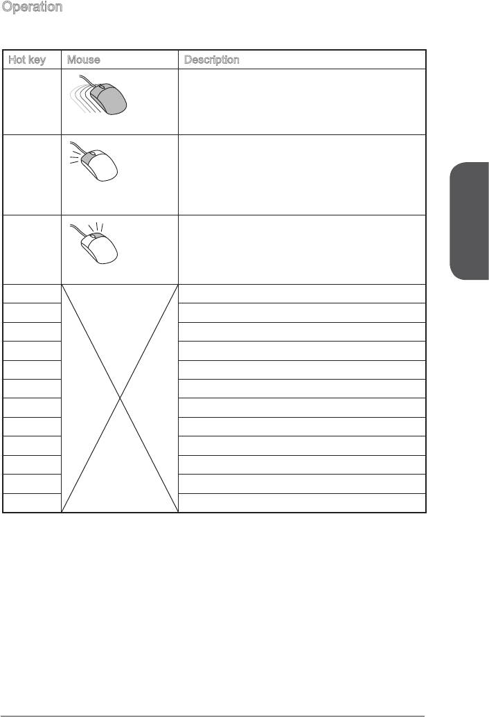
Operation
You can control BIOS settings with the mouse and the keyboard. The following table
lists and describes the hot keys and the mouse operations.
Hot key Mouse Description
Select Item
.
Move the cursor
<Enter>
Select Icon/ Field
Click/ Double-click
the left button
<Esc>
Jump to the Exit menu or return to the previous
from a submenu
English
Click the right button
<+> Increase the numeric value or make changes
<-> Decrease the numeric value or make changes
<F1> General Help
<F2> Favorites assistant
Enter My Favorites menu
<F4>
<F5> Enter Memory-Z
<F6>
<F8>
<F9>
<F10> Save Change and Reset
<F12>
En-41
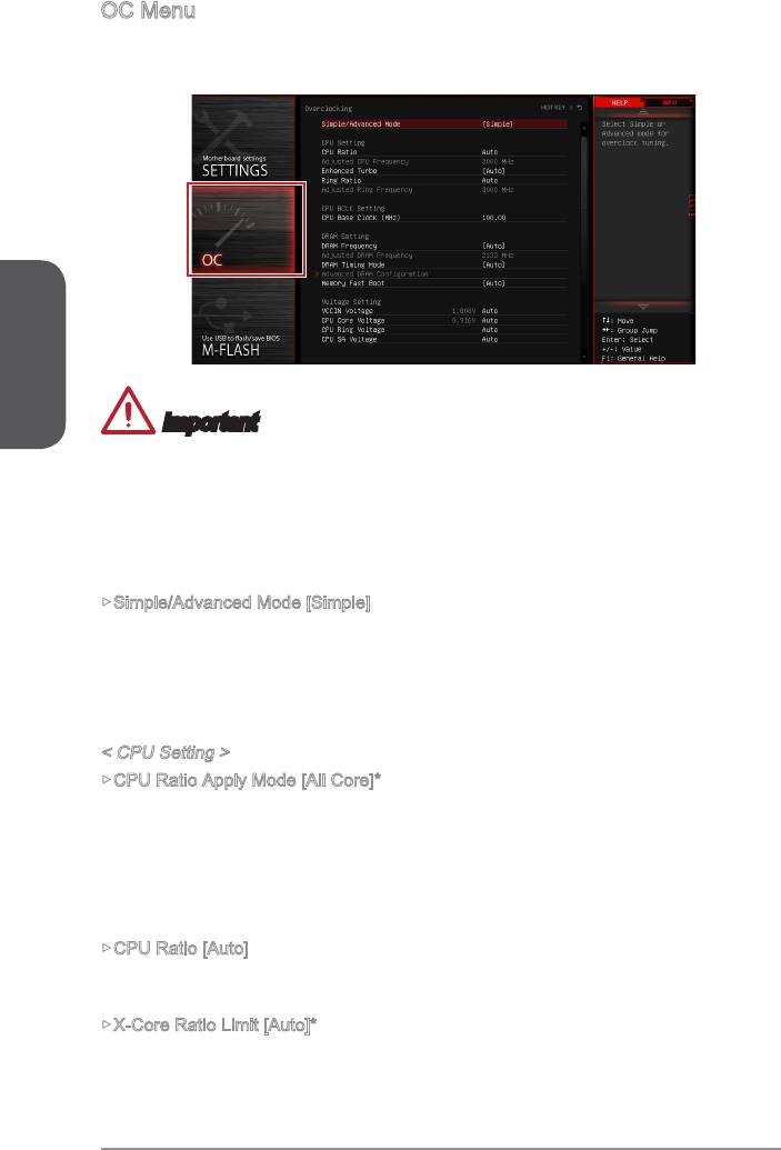
OC Menu
This menu is for advanced users who want to overclock the motherboard.
English
Important
Overclocking your PC manually is only recommended for advanced users.
Overclocking is not guaranteed, and if done improperly, can void your warranty or
severely damage your hardware.
If you are unfamiliar with overclocking, we advise you to use OC Genie for easy
overclocking.
Simple/Advanced Mode [Simple]
Enables or disables the advanced OC settings in BIOS.
[Simple] Provides the regular OC settings in BIOS setup.
in BIOS setup.
Note: We use * as the symbol for the OC settings of Advanced mode.
< CPU Setting >
CPU Ratio Apply Mode [All Core]*
Sets the applying mode for adjusted CPU ratio. This item only appears when a CPU
that support “Turbo Boost” is installed.
[All Core] Enables the "CPU Ratio". All CPU cores will run the same CPU ratio
that be set in " Adjust CPU Ratio".
[Per Core] Enables the "X-Core Ratio Limit". Sets each CPU core ratio separately
in "X-Core Ratio Limit".
CPU Ratio [Auto]
Sets the CPU ratio that is used to determine CPU clock speed for all cores. This item
can only be changed if the processor supports this function.
X-Core Ratio Limit [Auto]*
These items only appear when a CPU that support this function is installed. These
En-42

Adjusted CPU Frequency
Shows the adjusted CPU frequency. Read-only.
CPU Ratio Mode [Dynamic Mode]*
Selects the CPU Ratio operating mode. This item will appear when you set the CPU
ratio manually.
[Fixed Mode] Fixes the CPU ratio.
[Dynamic Mode] CPU ratio will be changed dynamically according to the CPU
loading.
EIST [Enabled]*
®
Enables or disables the Enhanced Intel
SpeedStep Technology.
[Enabled] Enables the EIST to adjust CPU voltage and core frequency
dynamically. It can decrease average power consumption and average
heat production.
[Disabled] Disables EIST.
Intel Turbo Boost [Enabled]*
®
Enables or disables the Intel
Turbo Boost. This item appears when the installed CPU
English
supports this function.
[Enabled] Enables this function to boost CPU performance automatically above
state.
[Disabled] Disables this function.
Enhanced Turbo [Auto]
Enables or disables Enhanced Turbo function for all CPU cores to boost CPU
performance. This item appears when the installed CPU supports this function.
[Enabled] All CPU cores would be increased to maximum turbo ratio.
[Disabled] Disables this function.
OC Genie Function Control [By Onboard Button]
Enables the OC Genie function by virtual button in BIOS or physical button on
motherboard. Enabling OC Genie function can automatically overclock the system
[By BIOS Options] OC Genie function is enabled by clicking the virtual OC Genie
button at the top left corner of BIOS setup screen.
[By Onboard Button]OC Genie function is enabled by pressing the physical OC Genie
button on the motherboard.
Ring Ratio [Auto]
Sets the ring ratio. The valid value range depends on the installed CPU.
Adjusted Ring Frequency
Shows the adjusted Ring frequency. Read-only.
< CPU BCLK Setting >
Sets the CPU Base clock. You may overclock the CPU by adjusting this value. Please
note that overclocking behavior and stability is not guaranteed. This item appears
when the installed processor supports this function.
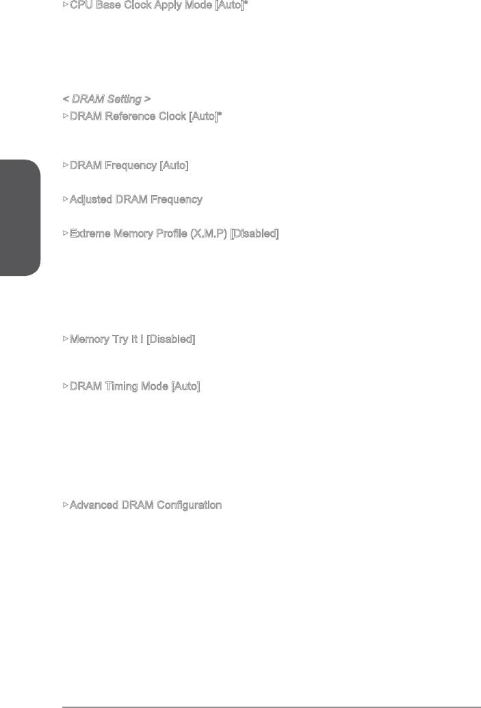
CPU Base Clock Apply Mode [Auto]*
Sets the applying mode for adjusted CPU base clock.
[Next Boot] CPU will run the adjusted CPU base clock at next boot.
[Immediate] CPU runs the adjusted CPU base clock immediately.
[During Boot] CPU will run the adjusted CPU base clock during boot.
< DRAM Setting >
DRAM Reference Clock [Auto]*
Sets the DRAM reference clock. The valid value range depends on the installed CPU.
This item appears when a CPU that supports this adjustment is installed.
DRAM Frequency [Auto]
Sets the DRAM frequency. Please note the overclocking behavior is not guaranteed.
English
Adjusted DRAM Frequency
Shows the adjusted DRAM frequency. Read-only.
This item will be available when you install the memory modules that support X.M.P.
technology.
[Disabled] Disables this function.
Memory Try It ! [Disabled]
preset.
DRAM Timing Mode [Auto]
Selects the memory timing mode.
[Auto] DRAM timings will be determined based on SPD (Serial Presence
Detect) of installed memory modules.
channel.
memory channel.
Press <Enter> to enter the sub-menu. This sub-menu will be activated after setting
[Link] or [Unlink] in “DRAM Timing Mode”. User can set the memory timing for each
memory channel. The system may become unstable or unbootable after changing
memory timing. If it occurs, please clear the CMOS data and restore the default
settings. (Refer to the Clear CMOS jumper/ button section to clear the CMOS data,
and enter the BIOS to load the default settings.)
En-44

Memory Fast Boot [Auto]
Enables or disables the initiation and training for memory every booting.
training. After that, the memory will not be initialed and trained when
booting to accelerate the system booting time.
[Disabled] The memory will be initialed and trained every booting.
< Voltage Setting >
DigitALL Power
Press <Enter> to enter the sub-menu. Controls the digital powers related to CPU
PWM.
VR 12VIN OCP Expander [Auto]
Expands the limitation of VR Over Current Protection with 12V input voltage. The
higher expanding value indicates less protection. Therefore, please adjust the
current carefully if needed, or it may damage the CPU/ VR MOS. If set to "Auto",
English
CPU Phase Control [Auto]
Controls PWM phase proportionally to the CPU loading. If set to "Auto", BIOS will
system with an optimum power-saving capability.
[Disabled] Disables the PWM power phase switching feature.
CPU Vdroop Offset Control [Auto]
CPU Over Voltage Protection [Auto]
Sets the voltage limit for CPU over-voltage protection. If set to "Auto", BIOS will
may damage the system.
CPU Under Voltage Protection [Auto]
Sets the voltage limit for CPU under-voltage protection. If set to “Auto”, BIOS will
may damage the system.
CPU Over Current Protection [Auto]
Sets the current limit for CPU over-current protection. If set to “Auto”, BIOS will
damage the system.
CPU Switching Frequency [Auto]
range. Increasing the PWM working speed will cause higher temperature of
MOSFET. So please make sure a cooling solution is well-prepared for MOSFET
automatically.
En-45
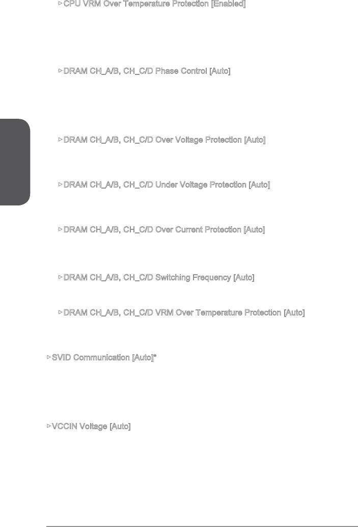
CPU VRM Over Temperature Protection [Enabled]
Enables or disables the CPU VRM over-temperature protection.
[Enabled] Sets the temperature limit on CPU VRM for over-temperature
protection. The CPU frequency may be throttled when CPU
[Disabled] Disables this function.
DRAM CH_A/B, CH_C/D Phase Control [Auto]
Controls PWM phase proportionally to the DRAM loading. If set to "Auto", BIOS
[Disabled] Disables the PWM power phase switching feature.
English
DRAM CH_A/B, CH_C/D Over Voltage Protection [Auto]
Sets the voltage limit for DRAM over-voltage protection. If set to "Auto", BIOS will
may damage the system.
DRAM CH_A/B, CH_C/D Under Voltage Protection [Auto]
Sets the voltage limit for DRAM under-voltage protection. If set to "Auto", BIOS
may damage the system.
DRAM CH_A/B, CH_C/D Over Current Protection [Auto]
Sets the current limit for DRAM over-current protection.
[Enhanced] Extends the limitation of memory over-current protection.
DRAM CH_A/B, CH_C/D Switching Frequency [Auto]
DRAM CH_A/B, CH_C/D VRM Over Temperature Protection [Auto]
Sets the temperature limit on DRAM VRM for over-temperature protection.
SVID Communication [Auto]*
[Enabled] PWM phase will be changed dynamically according to the CPU SVID
VCCIN Voltage [Auto]
Sets the CPU input voltage. The CPU input voltage is the CPU power source that is
shared with components of the CPU.
En-46

CPU Core/Ring Voltage Mode [Auto]*
Selects the control mode for CPU Core/ Ring voltages.
performance.
[Override Mode] Allows you to set the voltage manually.
CPU Core Voltage/ CPU Ring Voltage [Auto]
Sets the CPU Core/ Ring voltages. If set to “Auto”, BIOS will set these voltages
automatically or you can set it manually. This item appears when “CPU Core/Ring
Voltage Mode” sets to [Auto]/ [Adaptive Mode]/ [Override Mode].
English
voltages automatically or you can set it manually. This item appears when “CPU Core/
CPU SA Voltage Mode [Manual Mode]*
Selects the control mode for CPU SA voltage.
[Manual] Allows you to set the voltage manually.
automatically or you can set it manually. This item appears when “CPU SA Voltage
CPU SA Voltage [Auto]
Sets the CPU SA voltage. If set to “Auto”, BIOS will set these voltages automatically
or you can set it manually. This item appears when “CPU SA Voltage Mode” sets to
[Manual Mode].
En-47
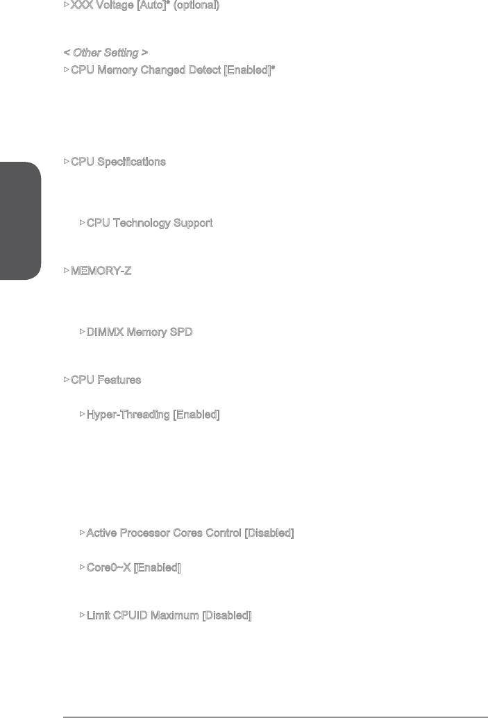
XXX Voltage [Auto]* (optional)
Sets the voltages related to memory/ PCH. If set to "Auto", BIOS will set the voltage
automatically or you can set it manually.
< Other Setting >
CPU Memory Changed Detect [Enabled]*
Enables or disables the system to issue a warning message during boot when the
CPU or memory has been replaced.
[Enabled] The system will issue a warning message during boot and than needs
to load the default settings for new devices.
[Disabled] Disables this function and keeps the current BIOS settings.
Press <Enter> to enter the sub-menu. This sub-menu displays the information of
English
installed CPU. You can also access this information menu at any time by pressing
[F4]. Read only.
CPU Technology Support
Press <Enter> to enter the sub-menu. The sub-menu shows what the key features
does the installed CPU support. Read only.
MEMORY-Z
Press <Enter> to enter the sub-menu. This sub-menu displays all the settings and
timings of installed memory. You can also access this information menu at any time by
pressing [F5].
DIMMX Memory SPD
Press <Enter> to enter the sub-menu. The sub-menu displays the information of
installed memory. Read only.
CPU Features
Press <Enter> to enter the sub-menu.
Hyper-Threading [Enabled]
The processor uses Hyper-Threading technology to increase transaction rates
and reduces end-user response times. Intel Hyper-Threading technology treats
the multi cores inside the processor as multi logical processors that can execute
instructions simultaneously. In this way, the system performance is highly
improved. This item appears when the installed CPU supports this setting.
[Enable] Enables Intel Hyper-Threading technology.
[Disabled] Disables this item if the system does not support HT function.
Active Processor Cores Control [Disabled]
Enables or disables the following items (Core0~X).
Core0~X [Enabled]
Enables or disables the CPU core. These items only appear when “Active
Processor Cores Control” is enabled.
Limit CPUID Maximum [Disabled]
Enables or disables the extended CPUID value.
[Enabled] BIOS will limit the maximum CPUID input value to circumvent
boot problems with older operating system that do not support the
processor with extended CPUID value.
[Disabled] Use the actual maximum CPUID input value.
En-48
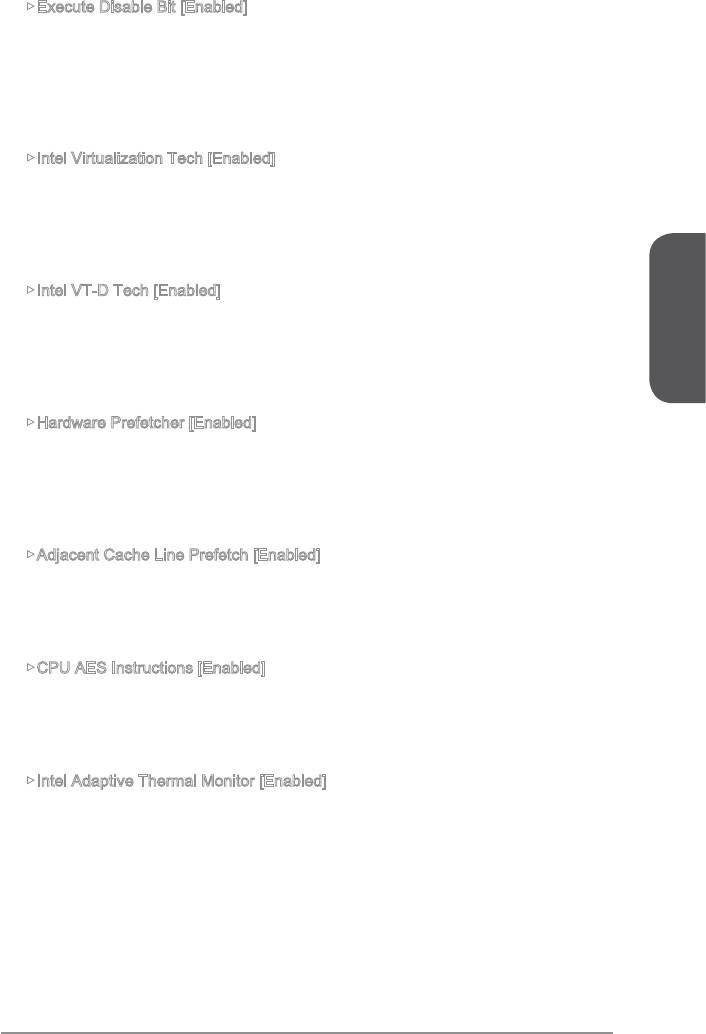
Execute Disable Bit [Enabled]
Intel’s Execute Disable Bit functionality can prevent certain classes of malicious
system. It is recommended that keeps this item enabled always.
[Enabled] Enables NO-Execution protection to prevent the malicious attacks
and worms.
[Disabled] Disables this function.
multiple operating systems in independent partitions. The system
can function as multiple systems virtually.
[Disabled] Disables this function.
Intel VT-D Tech [Enabled]
[Enabled] Enables Intel VT-D technology and allows a platform to run multiple
operating systems in independent partitions. The system can
English
function as multiple systems virtually.
[Disabled] Disables this function.
Hardware Prefetcher [Enabled]
Enables or disables the hardware prefetcher (MLC Streamer prefetcher).
[Enabled] Allows the hardware prefetcher to automatically pre-fetch data
and instructions into L2 cache from memory for tuning the CPU
performance.
[Disabled] Disables the hardware prefetcher.
Adjacent Cache Line Prefetch [Enabled]
Enables or disables the CPU hardware prefetcher (MLC Spatial prefetcher).
[Enabled] Enables adjacent cache line prefetching for reducing the cache
[Disabled] Enables the requested cache line only.
CPU AES Instructions [Enabled]
Enables or disables the CPU AES (Advanced Encryption Standard-New
Instructions) support. This item appears when a CPU supports this function.
[Enabled] Enables Intel AES support.
[Disabled] Disables Intel AES support.
Intel Adaptive Thermal Monitor [Enabled]
Enables or disables the Intel adaptive thermal monitor function to protect the CPU
from overheating.
[Enabled] Throttles down the CPU core clock speed when the CPU is over the
adaptive temperature.
[Disabled] Disables this function.
En-49

Intel C-State [Enabled]
[Enabled] Detects the idle state of system and reduce CPU power consumption
accordingly.
[Disabled] Disable this function.
C1E Support [Disabled]
Enables or disables the C1E function for power-saving in halt state. This item
appears when “Intel C-State” is enabled.
[Enabled] Enables C1E function to reduce the CPU frequency and voltage for
power-saving in halt state.
[Disabled] Disables this function.
English
Package C State limit [Auto]
This item allows you to select a CPU C-state mode for power-saving when system
is idle. This item appears when "Intel C-State" is enabled.
[C0~C6] The power-saving level from high to low is C6, C2, then C0.
EIST [Enabled]
®
Enables or disables the Enhanced Intel
SpeedStep Technology. This item will
appear when “Simple/ Advanced Mode” is set to [Simple].
[Enabled] Enables the EIST to adjust CPU voltage and core frequency
dynamically. It can decrease average power consumption and
average heat production.
[Disabled] Disables EIST.
Intel Turbo Boost [Enabled]
®
Enables or disables the Intel
Turbo Boost. This item is for Simple mode and
appears when the installed CPU supports this function.
[Enabled] Enables this function to boost CPU performance automatically above
state.
[Disabled] Disables this function.
Long Duration Power Limit (W) [Auto]
Sets the long duration TDP power limit for CPU in Turbo Boost mode.
Long Duration Maintained (s) [Default]
Sets the maintaining time for "Long duration power Limit(W)".
Short Duration Power Limit (W) [Auto]
Sets the short duration TDP power limit for CPU in Turbo Boost mode.
CPU Current Limit (A) [Auto]
Sets maximum current limit of CPU package in Turbo Boost mode. When the
frequency for reducing the current.
En-50

Internal VR OVP OCP Protection [Auto]
Enables or disables the over-voltage protection and over-current protection for
CPU internal VR (Voltage Regulator).
[Enabled] Enables the limitation of internal VR for over-voltage protection and
over-current protection.
[Disabled] Disables this function for overclocking.
Internal VR Efficiency Management [Auto]
[Disabled] Disables this function.
DMI Gen 2 [Enabled]
Enables or disables DMI (Direct Media Interface) generation 2.
DMI De-emphasis Control [-6dB]
Sets the de-emphasis value to improve DMI margins. However, the default usually
English
works best.
En-51