Ingersoll-Rand 301: инструкция
Раздел: Инструмент, электроинструмент, силовая техника
Тип:
Инструкция к Ingersoll-Rand 301
16573487
Edition 6
July 2006
Air Die Grinder
301, 301-EU, 307A, 307A-EU, 308A, 308A-EU,
3102, 3102-EU, 3107G, 3108 and 3108-EU
Product Information
EN
Product Information
SL
Specikacije izdelka
ES
Especicaciones del producto
SK
Špecikácie produktu
FR
Spécications du produit
CS
Specikace výrobku
IT
Speciche prodotto
ET
Toote spetsikatsioon
DE
Technische Produktdaten
HU
A termék jellemzői
NL
Productspecicaties
LT
Gaminio techniniai duomenys
DA
Produktspecikationer
LV
Ierices specikacijas
SV
Produktspecikationer
PL
Dane techniczne narzędzia Rozmiar
NO
Produktspesikasjoner
RU
Технические характеристики изделия
FI
Tuote-erittely
ZH
产品信息
PT
Especicações do Produto
JA
製品仕様
EL
Προδιαγραφές προϊόντος
KO
제품 상세
Save These Instructions
2 16573487_ed6
PMAX
9
3
2
6
10
1
48h
8h
PMAX
4
6
24h
8
7
5
(Dwg.16573164)
1
2
3
5
6
7
9
10
3
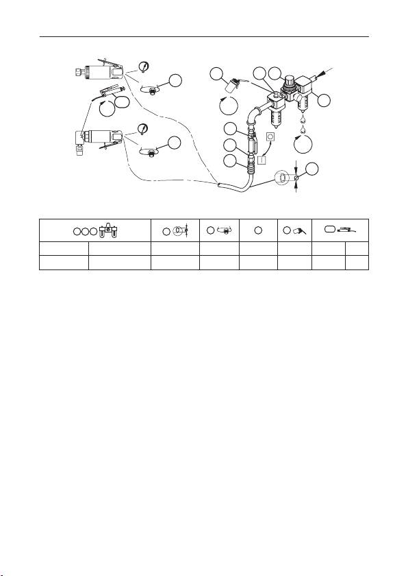
I-R # - NPT I-R # - BS inch (mm) NPT I-R # I-R # I-R # cm
C241-810 C28241-810-B 3/8 (10) 1/4 MSCF32 10 67 2
EN
Product Safety Information
Intended Use:
These die grinders are designed for grinding, porting, polishing, de-burring, and breaking
sharp edges.
For additional information refer to Air Die Grinder Product Safety Information Manual
Form 04580288.
Manuals can be downloaded from www.irtools.com.
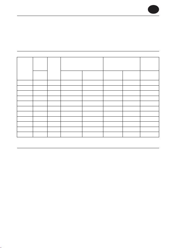
Product Specications
Vibration
Free
Sound Level dB (A)
Sound Level dB (A)
Level
Speed
Collet
(ISO15744)
(ANSI S5.1-1971)
Model(s)
(ISO8662)
Size
† Pressure
Power
rpm
‡ Power (L
) Pressure
m/s²
w
(L
)
(ISO3744)
p
301 20,000 1/4” --- --- 91.8 104.8 3.3
301-EU 20,000 6 mm --- --- 91.8 104.8 3.3
307A 27,000 1/4” 83.0 94.0 --- --- 4.9
307A-EU 27,000 6 mm 83.0 94.0 --- --- 4.9
308A 25,000 1/4” 91.0 102.0 --- --- 4.0
308A-EU 25,000 6 mm 91.0 102.0 --- --- 4.0
3102 20,000 1/4” 90.0 101.0 --- --- 2.5
3102-EU 20,000 6 mm 90.0 101.0 --- --- 2.5
3107G 27,000 1/4” 92.4 103.4 --- --- 2.6
3108 25,000 1/4” 92.0 103.0 --- --- 3.4
3108-EU 25,000 6 mm 92.0 103.0 --- --- 3.4
† K
= 3dB measurement uncertanity
pA
‡ K
= 3dB measurement uncertanity
wA
Installation and Lubrication
Size air supply line to ensure tool’s maximum operating pressure (PMAX) at tool inlet. Drain
condensate from valve(s) at low point(s) of piping, air lter and compressor tank daily. Install a
properly sized Safety Air Fuse upstream of hose and use an anti-whip device across any hose
coupling without internal shut-o, to prevent hose whipping if a hose fails or coupling discon-
nects. See drawing 16573164 and table on page 2. Maintenance frequency is shown in circular
arrow and dened as h=hours, d=days, and m=months. Items identied as:
1. Air lter 6. Thread size
2. Regulator 7. Coupling
3. Lubricator 8. Safety Air Fuse
4. Emergency shut-o valve 9. Oil
5. Hose diameter 10. Grease - through tting
16573487_ed6 EN-1
