ABUS TVHD80110 Operating instructions – страница 6
Инструкция к ABUS TVHD80110 Operating instructions
Оглавление
- Инструкция по эксплуатации
Camera
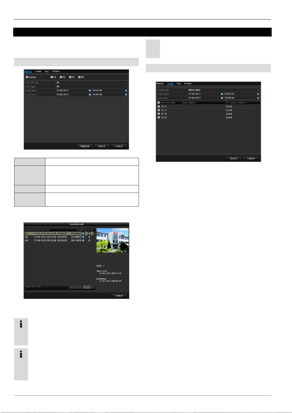
Playback
Press Configuration in the main menu and then Play-
back to search for video recordings after an event or a
marking, or to view your saved images.
Continous Recording
The following settings are available:
101
A1 - A4
Camera to be set
Record Type
Schedule, motion detection, alarm or mo-
tion detection and/or alarm, manual re-
cording, all
File Type
Locked, unlocked, all
Start Time
End Time
Enter the date and time
Click on Search to search for recordings with the cor-
responding settings. The results are then shown:
Select the recording by clicking on the line and then
on “Play”-symbol.
Note
You can return to events search at any time in the
playback mode by performing a right click and se-
lecting ‘Video Search’.
Note
The sub-menus ‘Tag’ and ‘Picture’ are almost iden-
tical with the menu described above and are there-
fore not listed separately.
In the sub-menu ‘Tag’, searching does not take
place according to recording type, rather according
to identification or a keyword of the markings’
name
Event
Please klick on the TAB „Event“.
A list of all event types is displayed.
For “Event Type” select whether a search is to be made
for recordings with motion (motion detection).
Select one or more cameras by activating the checkbox.
Click on Search.
Select one or more event markings from the list which
appears. Click on Details to obtain more information
about the recordings.
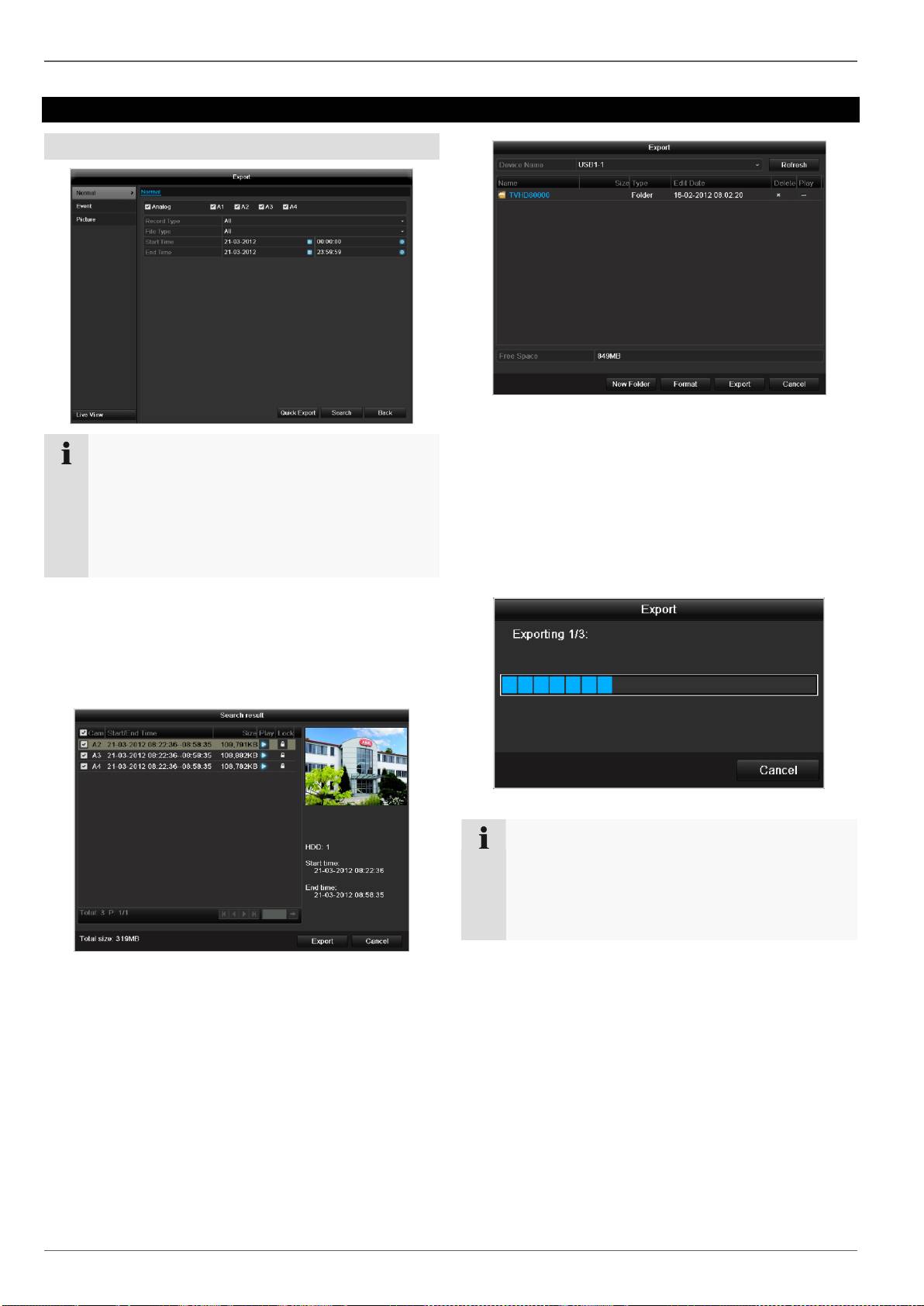
Video Export
Video Export
Duration
102
Note
The export function is used to store important re-
cordings on connected external media, such as:
USB media
USB HDD
DVD writer
1. Select the connected medium used for data storage
from the drop-down menu.
2. If the medium is not displayed, click on Refresh.
If the medium is still not displayed, disconnect it from
the device and reconnect the medium again. See al-
so the manufacturer’s specifications.
3. Click on Export to start the export process. The pro-
gress of the export process is then displayed.
When “Quick export” is selected, all recordings of the
selected time span are exported. Please note that not
more than 24 hours can be exported.
1. Enter the parameters.
2. Click on “Details” to limit the search
The file size of the individual recording and the total
size of all found recordings are displayed.
By clicking the “Playback” symbol you can view the
respective recording.
To block or unblock a file click on the “Lock” symbol.
3. Click on Export to access the export screen.
Note
After the storage process is completed, the data on
the medium can be selected and played on the
player (which was also backed up). In this way,
you can check whether the export has been made
successfully.
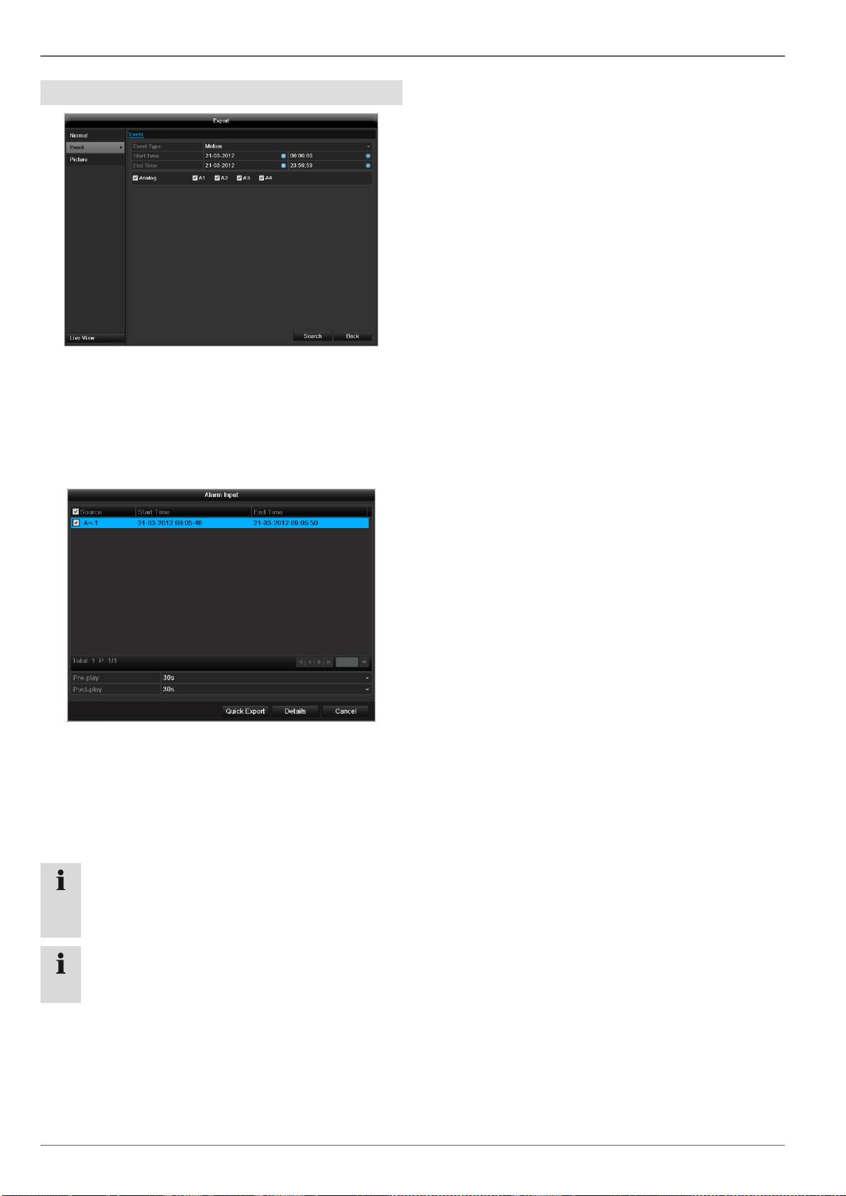
Video Export
Event (event type ‘Motion’)
Define the time span of the recording being searched for
by means of the selection fields at “Start time” and “End
time”. Select the camera by activating or deactivating the
check box and click Search.
For both types of event, the following window appears af-
ter activating the Search button:
Select the files to be exported by activating or deactivat-
ing the check box. You can set the pre-alarm and post-
alarm time at “Pre-play” or “Post-play”. In this way you
can define the length of your export video.
Click on Details to view the selected video. For more ex-
act information on the Details window, see DURATION
(p. Fehler! Textmarke nicht definiert.).
103
Note
The “Pre-play” recordings can only be viewed
when recording has been carried out before the
alarm.
Note
The sub-menus “Normal” and “Picture” are similar
and are therefore not listed separately.
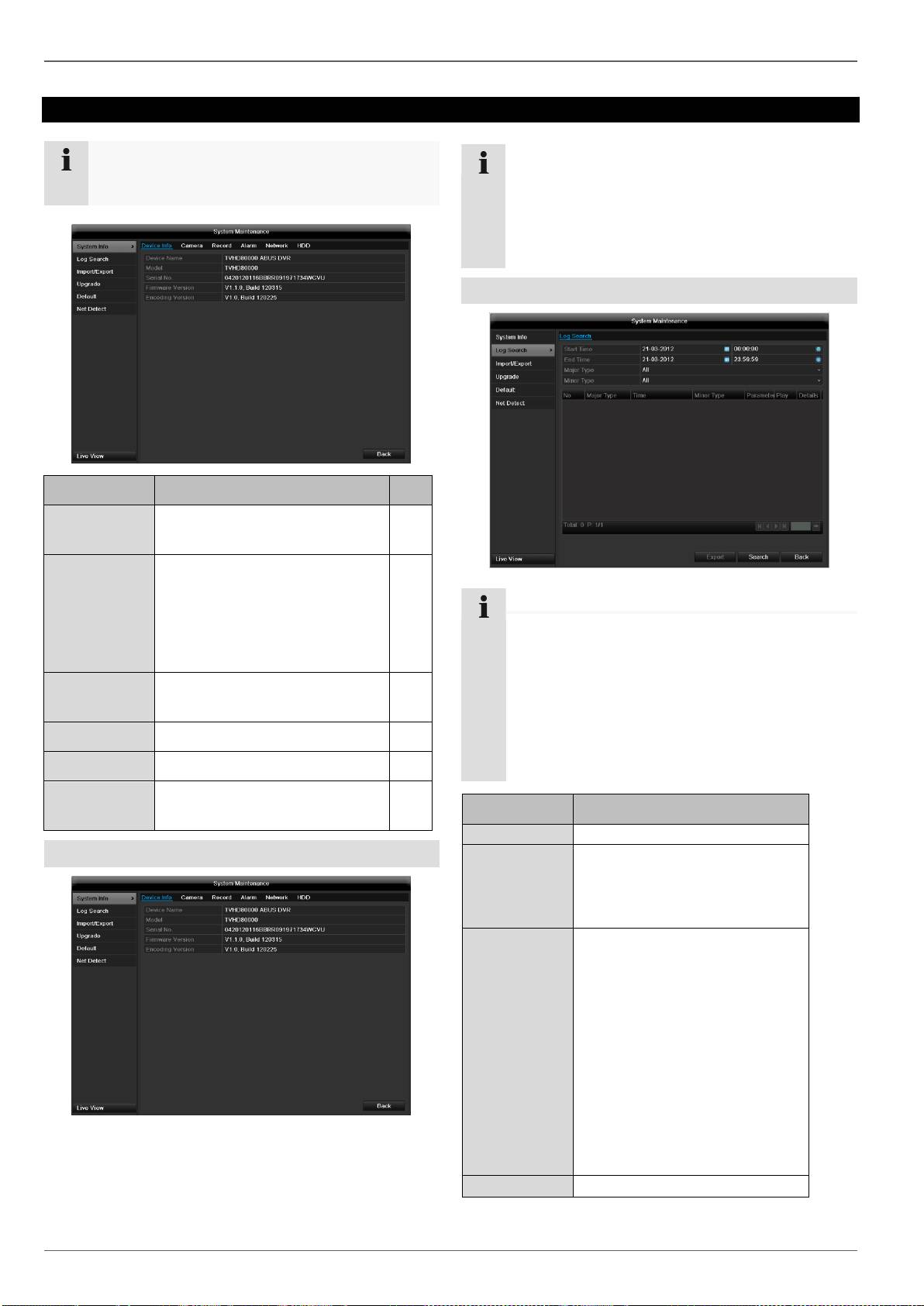
Maintenance
Maintenance
104
Note
This menu is used for device maintenance, and
should only be operated by experienced users.
Menu
Setting
P.
System Info
Device information (serial num-
ber, firmware status etc.)
104
Log Search
A search of recordings or in-
formation (S.M.A.R.T. HDD sta-
tus) can be made in the log file
according to certain criteria
(alarms, exceptions, operation
or information).
104
Import/Export
Used to export or import the
settings
105
Upgrade
Carries out a firmware upgrade
105
Default
System reset
106
Network
Displays the transmission and
reception rate of the recorder
106
System Info
Note
The information menu shows the technical data
for the device and information on the various set-
tings of the cameras, recording etc.
This can be useful for support queries, for exam-
ple.
Log Search
Note
An event search can be made according to the fol-
lowing main types, events and parameters:
All
Alarm
Exception
Operation
Information
Filter1
Filter2
All
-
Alarm
All
Alarm Input/Output
Start/Stop Motion Detection
Start/Stop Tamper-proof
Exception
All
Video Loss Signal
Video Signal Exception
Illegal Login
HDD Full
HDD Error
IP Conflicted
Network Disconnected
Exception recording
Video input/output signal
not equal
Recorder buffer overflow
Operation
All
Maintenance
105
Power On
Abnormal Shutdown
Start/Stop Audio
Local Operation, e.g.:
Shutdown/Reboot/Login/
Logout/Configure Parame-
ters/Upgrade/Start Record-
ing
Remote Operation, e.g.:
Export Record File/Alarm
Arming/ ...
Information
All
Local HDD Information
HDD S.M.A.R.T.
Start/Stop Recording
Start/Stop Capture
Delete Expired Record
NetHDD Information
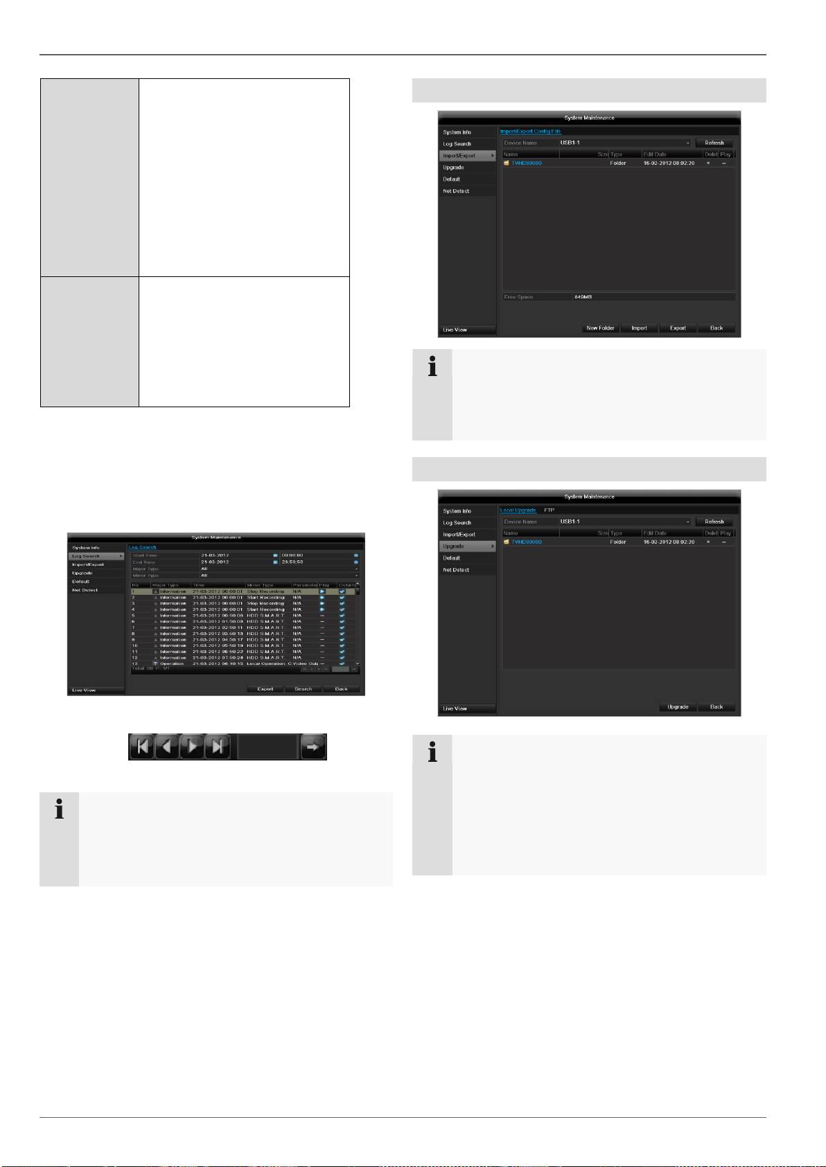
1.Select the event you wish to search for in the log, then
select the sub-parameter.
2.Enter the date and time under “Start Time” and “End
Time”, then click on Search.
3.The results are then displayed:
The pages are changed using the navigation bar:
(1) (2) (3) (4) (5) (6)
Note
To scroll forwards or backwards press (3) or (2).
To jump to the first or last page press (4) or (1).
To go to a specific page number enter it in (5) and
confirm by clicking (6).
Import / Export
Click on Details to see more detailed information.
Click on Play to start the recording for the event,
when necessary.
Click on Export to back up the log file on a USB me-
dium.
Note
The configuration data contains all settings made
on the device since the start of operation. This da-
ta can be saved on a USB medium. You can then
configure another device identically, for example.
Upgrade
Note
A device upgrade can be made from a USB de-
vice or over the network.
Copy the upgrade file to the main directory of a
USB stick.
Connect the USB stick to a USB port on the
device.
Maintenance
1. Select the USB port (click on Refresh, if necessary).
2. Select the upgrade file and click on Upgrade.
3. Wait until the device reboots.
4. Check the firmware status in the “Maintenance”
menu under “System Info”.
106
Note
Upgrades via FTP are made in the same
way as detailed above.
The PC must be in the same local network.
Set up a PC as an FTP server.
Enter the IP address of the FTP server .
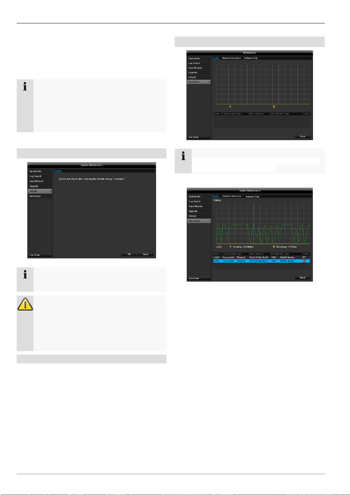
Default
Note
In this process, the device is reset to the factory de-
fault settings.
Warning
All settings made since the start of operation
are deleted (cameras, recording settings,
alarms etc.)!
Avoid data loss by backing up the settings in
advance. These can be imported again follow-
ing the system reset.
Network
Note
Information regarding the network traffic and net-
work interfaces are shown here.
TAB network load
The amount of received and sent data is displayed
graphically.
Depending on the network settings, the status and infor-
mation for one or two network connections is shown in
the field underneath the graph.
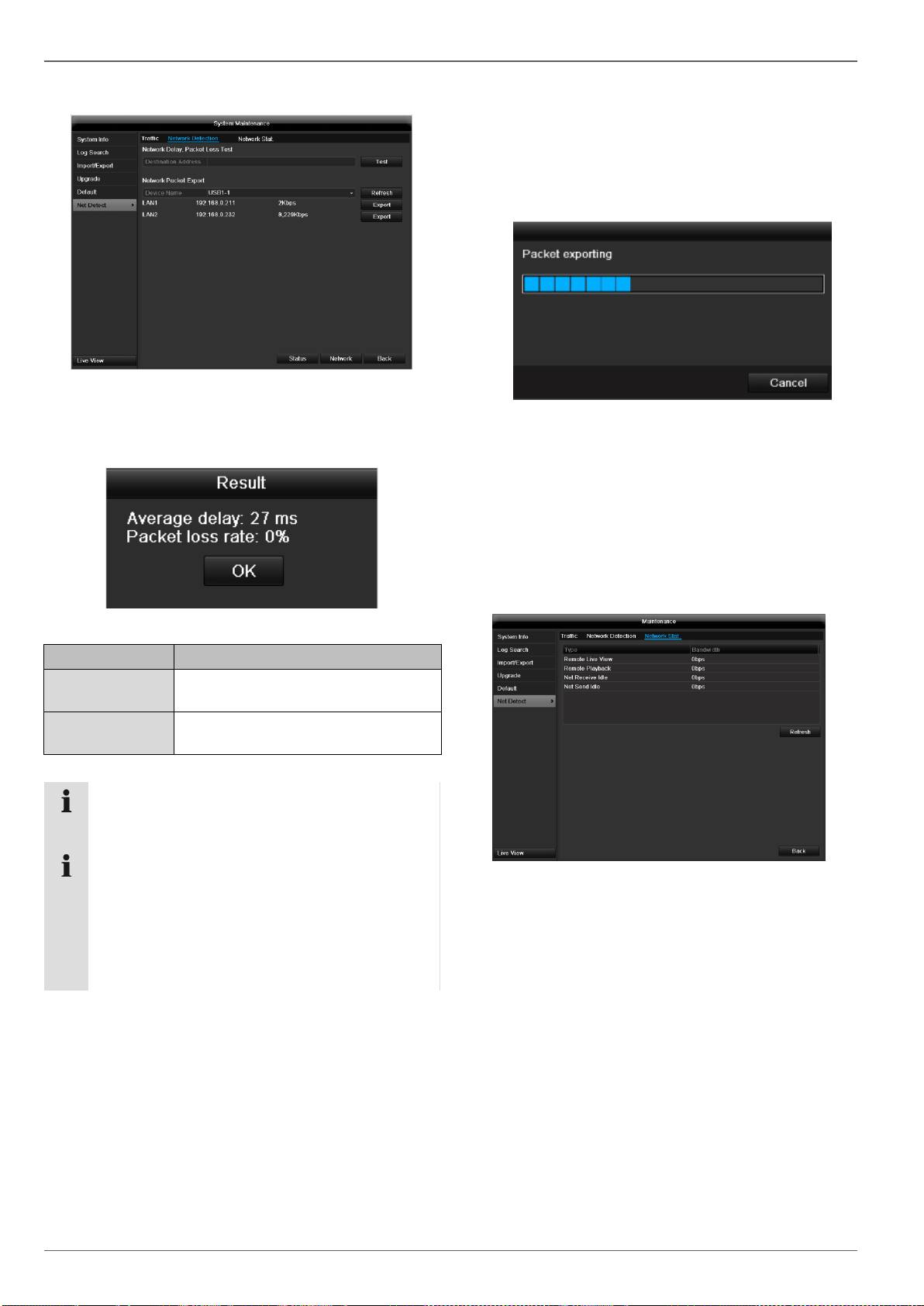
Maintenance
TAB Network Detection
In “Destination Address”, you can check the connection
to another device, such as a computer (‘pinging’). Enter
the network address of the device to be checked (e.g.
192.168.0.25) and press Test.
Information on two parameters appears:
107
Parameter
Setting
Average
delay
The time the pinged device needs to
reply.
Packet loss
Rate:
Displays the percentage of packets
that were not transmitted
Note
If the packet loss rate is high, we recommend that
the “Network Test” is repeated.
Note
If the packet loss rate is still high, you should
check that the cables are correct and not dam-
aged.
The higher the packet loss rate, the poorer the
connection between the pinged device and re-
corder.
For “Network Packet Export”, you can export the settings
of the individual connections or – depending on the set-
ting – the connection.
1. For “Device Name”, select a storage medium to save
the settings to.
2. Click Export.
After the progress display finishes and initializa-
tion is successful, an information window ap-
pears. Close it with OK.
Click Status to display the status of the LAN connec-
tions (connected/not connected).
Click Network to change your network settings (see
p. 85).
TAB Network Stat.
Displays all used in- and outcoming bandwidth.
You can refresh the data by clicking on Refresh.

Shutdown
Shutdown
108
Note
Select “Lock” to lock the operating menu.
Select “ShutDown” to switch off the device.
Select “Reboot” to reboot the system (switch
off and back on).

Troubleshooting
Troubleshooting
Before calling the Service department, read the following information to determine the possible cause of a malfunction.
109
Malfunction
Cause
Solution
No power
Mains cable not connected
Connect the mains cable securely to the
socket
Power switch set to OFF
Turn the power switch to ON
No current in the power socket
Use another device on the socket, where
necessary
No image
Screen not set for reception
Set the correct video input mode until an
image from the recorder appears
Video cable not connected properly
Connect the video cable securely
Connected modem is switched off
Switch on the monitor
No sound
Audio cables not connected properly
Connect the audio cables securely
Devices connected over the audio cables
are not switched on
Switch on the devices connected over the
audio cables
Audio connection cable is damaged
Replace the cable
HDD is not working
Connection cables not connected properly
Connect the cables securely
HDD defective or not system-compatible
Replace with a recommended HDD
USB port not working
Device not supported
Connect a compatible USB medium
(USB 2.0)
USB hub is in use
Connect the USB medium directly
Network access not possible
Network cable connections are loose
Connect the network cable
Network settings are incorrect (DHCP, IP
address etc.)
Check the network configuration and cor-
rect it, ifnecessary (see page 85).
Remote control is not working
Batteries inserted with the wrong polarity or
are empty
Replace the batteries. To control the de-
vice with the remote control, point it at the
remote control sensor on the device
Remote control too far away from the re-
corder
Use the remote controller within 7 metres
from the device
Signal blocked by obstruction between the
remote control and recorder
Remove the obstruction
Lighting too bright or fluorescent tubes in
use?
Switch off strong fluorescent lighting in the
immediate vicinity
Recording not possible
No HDD or HDD is not initialised
Install and initialise the HDD
Sudden deactivation of the
device
Temperature inside the device is too high
Clean the device and remove any obstruc-
tions from the ventilation area
Device cleaning and care
Note
Your device requires no maintenance.
Protect the device from dust, dirt and moisture.

Technical data
Technical data
Subject is to alterations and errors. The dimensions are approximate values.
110
ABUS digital recorder
TVHD80100
TVHD80110
Video compression
H.264
Camera inputs
4
8
Monitor outputs
Monitor: 1 x VGA, 1 x HDMI
Operating mode
Triplex
Resolution (live view)
VGA:
1080P: 1920*1080/60Hz, 1280*1024/60Hz,
720P: 1280*720/60Hz,1024*768/60Hz
HDMI:
1080P: 1920*1080/60Hz, 1280*1024/60Hz,
720P: 1280*720/60Hz,1024*768/60Hz
Resolution @ frame rate per
camera (recording)
352 x 288 @ 25 fps, 704 x 576 @ 25 fps, 1280 x 720 @ 25 fps, 1920 x 1080 @ 25 fps
Total frame rate
100 fps
200 fps
Compression levels
6
Post-alarm memory
0–30 sec. / 5–900 sec.
Storage medium
2 x 3.5“ SATA HDD
Data backup
2 x USB 2.0
Views
1 / 2 / 4 / 6 / 8 / 9
Recording modes
Manual, schedule, motion detection, alarm, motion detection and alarm,
motion detection or alarm
Search modes
By event, date and time, S.M.A.R.T.
User levels
2 (max. 31 users)
Network access
1 x RJ45 10/100 / 1000 Mbps
Parallel network access
128 camera connections
Network functions
Live view, playback, data export
DDNS
√
NTP
√
Alarms
Acoustic warning, OSD signal, e-mail, CMS
Control
USB mouse
OSD languages
German, English, French, Dutch, Danish,
Polish, Russian
Power supply
12 VDC, 3,3 A, 50~60 Hz
12 VDC, 5,0 A, 50~60 Hz
Power consumption
<20 W (without HDD)
Operating temperature
-10 °C ~ +55 °C
Dimensions (W x H x D)
400 x 45 x 275 mm
Weight
≤ 4.0 kg (without HDD)
Certifications
CE
HDD storage capacity
In addition to the actual storage capacity of the installed HDD, the required storage space for recording and surveil-
lance depends on the set resolution and frame rate of the recording.
On the included CD you can find a program in order to calculate the required amount of memory. In addition you find
this software for download on our homepage together with the ABUS CMS software.
Overview monitor output combination
It is possible to connect a SPOT monitor. Use the table below to find out what combinations are possible. A tick indi-
cates that the combination is possible, a cross shows that it is not.

Technical data
111
HDMI
+
VGA
HDMI
only
VGA
only

Disposal
Disposal
Information on the EU directive on waste
electrical and electronic equipment
To protect the environment, do not dispose of the device
with domestic waste at the end of its service life. It can be
disposed of at one of the appropriate collection points in
your country. Please obey your local regulations when
disposing of material.
112
Dispose of the device in accordance with EU di-
rective 2002/96/EC – WEEE (Waste Electrical
and Electronic Equipment). If you have any
questions, please contact the department of
your local authority which is responsible for
waste disposal. Used equipment can be dis-
posed of, for example, by your local or munici-
pal authority, the local waste disposal company
or your dealer.
Change low batteries in good time.
Always change all the batteries at the same time and
use batteries of the same type.
Information on handling batteries
Always insert batteries with the correct polarity. Never
attempt to recharge the batteries supplied and do not
throw them into naked flames under any circum-
stances. Do not use different batteries at the same
time (old and new, alkaline and zinc-carbon etc.).
Remove the batteries if the device is not used for a
long period of time. If used improperly, there is a risk
of explosion and leaking batteries!
Take environmental protection into account – used
batteries should not be disposed of in domestic
waste! They must be taken to a collection point for
used batteries.
Make sure that batteries are kept away from small
children. Children may put batteries in their mouths
and swallow them. This can cause serious harm to
their health. If this happens, consult a doctor immedi-
ately.
Do not charge normal batteries, heat them up or
throw them into naked flames (they may explode).
Important
Leaky or damaged batteries can cause chemical
burns on contact with the skin.
In this case, wear protective gloves.
Clean the battery compartment with a dry cloth.
Important information on disposing of
batteries
Your product uses batteries which are subject to the Eu-
ropean directive 2006/66/EC and may not be disposed of
with domestic waste.
Find out about the regulations for the separate collection
of batteries which apply in your country.
Proper disposal of batteries helps prevent harm to health
and the environment.
Batteries that contain harmful chemicals are labelled with
these signs:
Pb = battery contains lead
Cd = battery contains cadmium
Hg = battery contains mercury
Information on the European RoHS
directive
The device complies with the RoHS directive.
Compliance with the RoHS directive means that the
product or component does not contain more than the fol-
lowing maximum concentrations of the following sub-
stances in homogeneous materials, unless the substance
is part of an application that is excluded from the RoHS
directive:
a)0.1% lead (by weight)
b)Mercury
c)Hexavalent chromium
d)Polybrominated biphenyl (PBB) and polybrominated
diphenyl ether
e)0.01% cadmium (by weight)

Glossary
Glossary
Overview of specialist terms
1080i
Dual Stream
HDTV image signal with 1080 pixels and interlaced dis-
Dual stream is a video transmission method. A high-
play.
resolution recording and lower-resolution transmission
are made over the network, for example. The main
16:9
stream has a 4CIF resolution and the sub-stream has a
Cinematographic aspect ratio on widescreen displays.
CIF resolution.
720p
DVR
HDTV image signal with 1280 x 720 pixels and progres-
Digital Video Recorder – A device used for recording dif-
sive display.
ferent video and audio sources (analogue, digital). The
CIF
data is compressed for recording and saved on hard disk
Common Intermediate Format
drives (HDD).
Originally planned for converting PAL to the NTSC
H.264
standard. CIF corresponds to a video resolution of 352 x
(MPEG-4 AVC) – Standard method for the highly-efficient
288 pixels (2CIF = 704 x 288 pixels; 4CIF = 704 x 576
compression of video signals. Used on Blu-ray discs or
pixels).
video conference systems, for example.
CINCH
HDD
Socket type used for analogue audio or CVBS video sig-
Hard Disk Drive
nals.
Digital data storage on computers or DVRs.
CVBS
GIGABYTE
Colour, Video, Blank and Sync – The simplest variation
Unit of capacity for storage media (HDD, USB, SD/MMC
of video signals (also known as composite video). The
cards).
image quality is comparatively low.
HDVR
DDNS
Hybrid DVR – DVR used for recording analogue cameras
Dynamic Domain Name System entry
and network cameras.
Network service which provides and updates IP address-
http
es of its clients in a database.
Hypertext Transfer Protocol
DHCP
Method for transmitting data across networks. Primarily
Dynamic Host Configuration Protocol
used for displaying websites in a browser.
Network protocol which allows the automatic connection
INTERLACED
of devices (clients) in existing networks. DHCP servers
Method for improving the picture quality of a video signal
(e.g. Internet routers) automatically assign the IP ad-
without consuming extra bandwidth (scan pattern on eve-
dress, network mask, gateway, DNS server and WINS
ry second line).
server (when required). Only the automatic acquisition of
IP addresses must be activated for the client in this case.
IP address
Domain
An address in the computer network based on the Inter-
net protocol. Allows different devices to identify them-
Name used for the identification of websites on the Inter-
selves in a network so that they are accessed specifical-
net (e.g. www.abus-sc.de).
ly.
JPEG
Compression method for photo images with minimal loss.
Most digital cameras save photos in JPEG format.
113

Glossary
MPEG
PPPoE
Moving Picture Experts Group – International standard
PPP over Ethernet (point-to-point protocol)
for the compression of moving images. On some DVDs,
Network transmission method used for establishing a
the digital audio signals are compressed and recorded in
connection over dial-up lines. Used in ADSL connections,
this format.
for example).
NTP
PROGRESSIVE
Network Time Protocol
Method for displaying, storing or transmitting moving im-
Method for synchronising the time across networks.
ages in which all the lines of each frame are drawn in se-
SNTP (Simple Network Time Protocol) is also available,
quence. This is in contrast to the interlacing used in tradi-
offering a simplified protocol.
tional television systems.
NTSC
PTZ
Standard television format in the USA. The method is dif-
Pan-Tilt-Zoom
ferent from the European PAL system in certain ways. A
Pan, tilt and zoom function on motor-driven cameras.
full-screen NTSC image is comprised of 480 visible lines
RESOLUTION
and a total of 525 lines. 60 half-images are displayed per
Normal PAL television systems show images in 576
second. Compared to PAL, the system is more suscepti-
lines, normally with 768 pixels. HDTV works with at least
ble to colour errors.
1280 x 720 pixels.
PAL
SCREEN SIZE
Phase Alternating Line – European colour TV system.
Size of the display from the bottom-left corner to the top-
Uses 576 visible image lines. Together with the lines
right corner in inches or centimetres.
used for signal management, a full-screen image is com-
prised of 625 lines. 50 half-images are displayed per se-
Browser
cond. The phase position of the colour signal changes
Program for viewing websites on the Internet.
from line to line in the image.
USB
PANEL
Universal Serial Bus
Interior of a flatscreen display (e.g. LCD or plasma pan-
Serial bus connection, used for connecting media whilst
els).
in operation. Maximum data rate for USB 2.0: ca. 320
PC
Mbit/s (ca. 40 MB/s).
Personal Computer – Can be used as a remote site, ei-
VGA
ther with the software supplied or over a browser.
Video Graphics Array – Standard interface for analogue
Pixel
video signals in PCs (primarily deals with RGB signals).
Short for “picture element”, the smallest unit for digital
ZOLL (inches)
image transmission or display.
Typical unit of screen size. One inch is equivalent to 2.54
PIP
centimetres. The most common sizes of 16:9 displays
Picture in Picture – Where two signal sources are shown
are 26 inch (66 cm), 32 inch (81 cm), 37 inch (94 cm), 42
on the screen at the same time. The second signal
inch (106 cm), 50 inch (127 cm) and 65 inch (165 cm).
source is stored above the first.
114

Internal HDD
Internal HDD
The internal hard disk drive (HDD) is very sensitive. Operate the device according to the following instructions in order
to avoid drive errors. Important recordings should be backed up on external media to avoid unexpected data loss.
115
Note
Do not move the device during operation.
Moisture inside the device can condense and lead to HDD malfunctions.
When the device is turned on, never remove the mains plug from the socket or interrupt the power supply us-
ing the safety switch.
Do not move the device immediately after switching it off. To move the device, carry out the following steps:
1. Wait until OFF has been shown on the display for at least two minutes.
2. Remove the mains plug from the socket.
3. Move the device.
Data on the HDD can be lost in the event of a power failure during operation. Use an uninterruptible power
supply (UPS)!
The HDD is very sensitive. Improper use or unsuitable surroundings can damage the HDD after some years
of use. This may be indicated by the playback stopping unexpectedly or visible “mosaic” effects in the image.
In some circumstances, there are no prior signs of a HDD malfunction.
In the event of a malfunction, no recordings can be played. The HDD must be replaced in this case.

ABUS 4/8-channel HD-SDI digital
recorder
TVHD80100 / TVHD80110
Manufacturer:
ABUS Security-Center GmbH & Co. KG
Linker Kreuthweg 5
86444 Affing (Germany)
ABUS 4/8-kanaals HD-SDI digitale recorder
TVHD80100 / TVHD80110
Gebruikershandleiding
Version 1.0

118
Nederlands
Deze gebruikershandleiding bevat belangrijke
opmerkingen over de ingebruikneming en bediening.
Houd hier rekening mee, ook als u dit product aan
derden doorgeeft.
Bewaar daarom de gebruikershandleiding om deze na
te kunnen lezen!
U vindt een opsomming van de inhoud in de
inhoudsopgave met vermelding van de betreffende
paginanummers
Overzicht
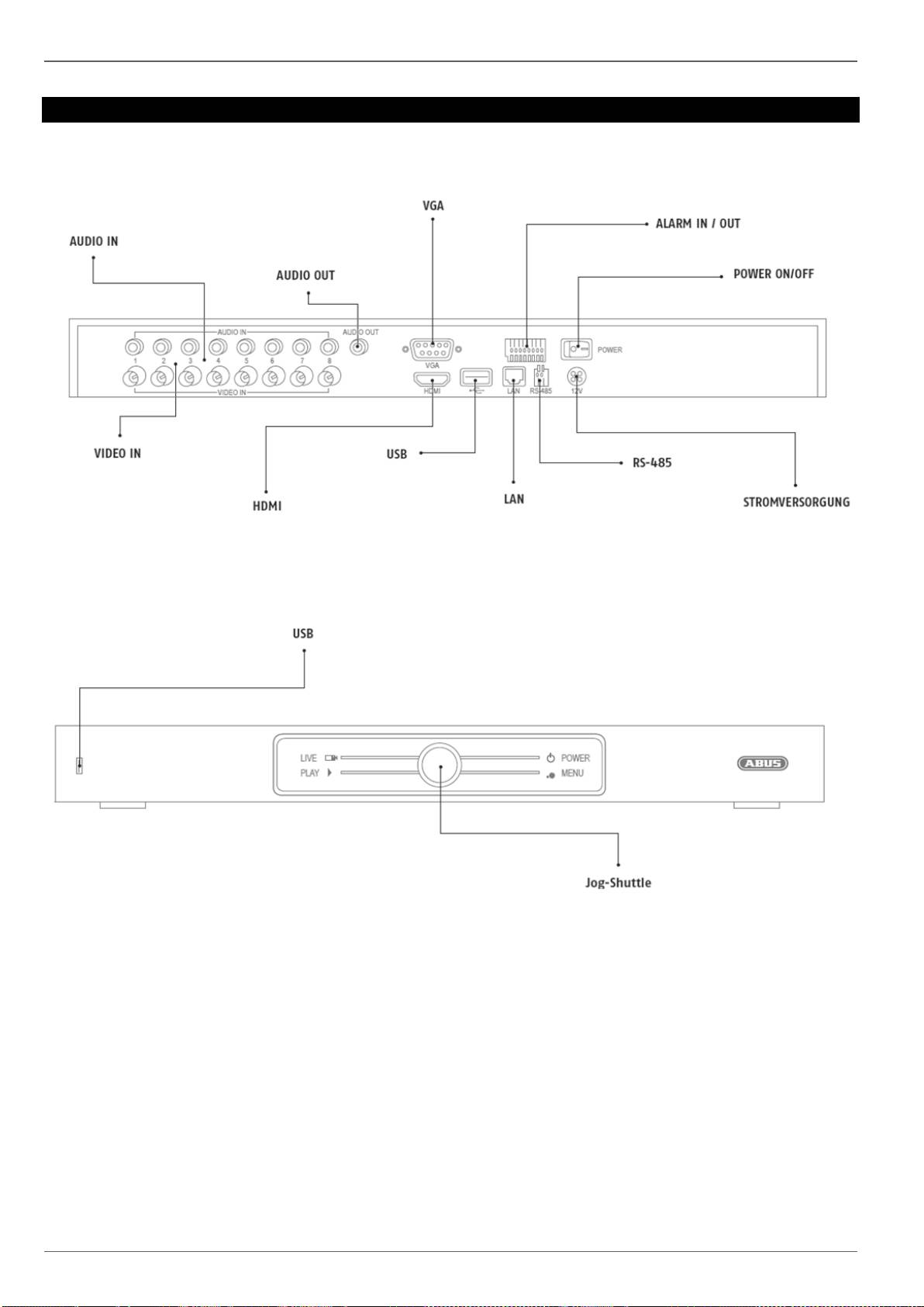
Overzicht
Achterkant
Voorzijde
119

Bediening van het systeem
Bediening van het systeem
Algemeen
U kunt de recorder op de volgende manieren bedienen:
USB-muis
Aansluitingen aan de achterkant
120
Opmerking
Neem het overzicht op p. 119 in acht.
Benaming
Functie
VIDEO IN:
BNC-ingang voor analoge camera’s
AUDIO IN:
cinch ingangen
AUDIO OUT:
audiouitgang cinch (gesynchroniseerd)
VGA:
monitoraansluiting VGA (9 pins),
videouitgangssignaal
ALARM IN / OUT:
max. 4 alarmingangen, max. 1
relaisuitgangen
POWER ON/OFF:
aan/uit-schakelaar van het apparaat
STROMVERSORGUNG
12 V DC stroomaansluiting
RS-485
aansluiting voor PTZ camera’s
LAN
RJ45-aansluiting voor een netwerkverbinding
USB
Aansluiting voor USB-apparaten
HDMI
HDMI monitor aansluiting
USB
Aansluiting voor USB-apparaten
JOG-SHUTTLE
Selectie van de bedrijfsmodus
