Bondioli&Pavesi 399CEBR15_A: instruction
Class: Car Accessories
Type:
Manual for Bondioli&Pavesi 399CEBR15_A

BP COMPONENTES HIDRÁULICOS E MECÂNICOS
CAXIAS DO SUL - RS - BRASIL
MADE IN BRAZIL
399CEBR015/A
BP COMPONENTES HIDRÁULICOS E MECÂNICOS
CAXIAS DO SUL - RS
MADE IN BRAZIL
G1 G2 G4 G5 G7
2013 2014 2015 2016
399FXBR05
Cod 399FXBR05
1
ROTATING DRIVE SHAFT
CONTACT CAN CAUSE DEATH
KEEP AWAY!
DO NOT OPERATE WITHOUT-
ALL DRIVELINE GUARDS, TRACTOR
AND EQUIPMENT SHIELDS IN PLACE
DRIVE SHAFT SECURELY
ATTACHED AT BOTH ENDS
DRIVE SHAFT GUARDS THAT TURN
FREELY ON DRIVE SHAFT
READING OPERATOR’S MANUAL
DO NOT USE PTO ADAPTORS
399141000
Cod 399141000
33
BP COMPONENTES HIDRÁULICOS E MECÂNICOS
CAXIAS DO SUL - RS
MADE IN BRAZIL
G1 G2 G4 G5 G7
2013 2014 2015 2016
399CEBR05
Cod 399CEBR05
Cod 399USR05
2 255
4
8
5
9
6
10
L
L
1/2 L
7
11
3
12
16
13
17
14
18
15
19
4
20
24
21
25
22
26
23
27
5
28
32
29
33
30
34
31
35
6
36
37
T
80
80
T
7
42
43
44
45
8
38
39
40
41
47
48
49
9
46
50
51
52
53

54
58
55
59
56
60
57
61
10

62
66
63
67
64
68
65
69
11

7470
71
75
72
76
73
77
12
78
82
79
83
80
84
81
85
13
86
87
14

ENG
TRANSLATION OF THE
ORIGINAL INSTRUCTIONS
ENGLISH
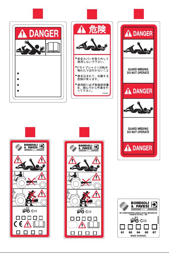
SAFETY LABELS
SHIELD TUBE LABEL Code 399141000
1
SHIELD TUBE LABEL Code 399JAP001
The operator must obey all labels and must maintain the proper shielding. A large
percentage of accidents caused by PTO drive shafts occur when the shielding is
not present or is not functioning correctly.
DRIVE TUBE LABEL Code 399143000
2
DRIVE TUBE LABEL Code 399USR05
DANGER! Keep clear of the work area and rotating parts.
Do not wear loose clothing, jewelry, or hair that could become entangled with the
driveline.
Contact with rotating parts can cause serious injury or death.
GUARD MISSING, DO NOT OPERATE.
Do not operate without all driveline, tractor and implement shields in place.
Damaged or missing parts must be repaired or replaced before using the driveline.
SHIELD TUBE LABEL Code 399CEBR05
3
SHIELD TUBE LABEL Code 399FXBR05
Rotating driveline – contact can cause death. Keep away. Do not wear loose
clothing, jewelry, or hair that could become entangled with the driveline.
Do not operate without all driveline, tractor and implement shields in place.
Damaged or missing parts must be replaced and installed correctly before using
the driveline. Disconnect PTO clutch, shut off tractor engine, and remove key
before approaching the implement. Keep all bystanders away from the implement
while in operation. Read this manual, and the operator’s manual for the implement,
before using the machine.
YOUR SAFETY DEPENDS UPON THIS INFORMATION.
SAFETY AND WORKING CONDITIONS
When using the implement and the driveline, do not exceed the speed
4
or power limits specified in the operator’s manual. Do not overload the
implement or suddenly engage the PTO clutch. Any torque limiter or clutch must
be installed on the implement end of the driveline. Use the implement only with
the original driveline, which is fit for the purpose in terms of length, dimensions,
devices and shields.
The driveline and its torque limiter or overrunning clutch are designed specifically
for the implement, and should be used exclusively for this purpose. Check the
implement instruction handbook to ascertain whether the driveline must be
equipped with a torque limiting or overrunning clutch. Standard drivelines, torque
–1
limiters and overrunning clutches are designed for speeds of up to 1000 min
.
Ensure that the driveline can perform all operations without interfering with the
tractor or the machine. Contact with parts of the tractor, hooks, drive pins, tires,
drawbar, hammerstrap, or 3-point hitch, will damage the guard. Never use tractors,
(or systems for connection to the implement) that interfere with the driveline du-
ring operation. Do not use adapters or components not offered by the implement
manufacturer.
15

ENG
NOMINAL POWER Pn and NOMINAL TORQUE Mn
-1
-1
540 min
1000 min
Pn Mn Pn Mn
kW CV-HP-PS N∙m kW CV-HP-PS N∙m
G1 12 16 210 18 25 172
G2 15 21 270 23 31 220
G3 26 35 460 40 55 380
G4 26 35 460 40 55 380
G5 35 47 620 54 74 520
G7 47 64 830 74 100 710
G8 61 83 1080 96 130 917
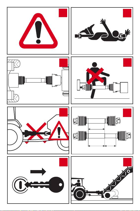
All rotating parts must be shielded.
5
The tractor master shield, the driveline guard, and the implement shield all
work together for your safety.
Do not operate without all driveline, tractor and implement shields in place.
6
Damaged or missing parts must be repaired with original spare parts or
replaced before using the driveline. The driveline must be securely attached at
both ends. Guards must turn freely on the driveline.
Disengage the PTO, turn off the tractor engine, remove the key and ensure
7
that all rotating parts have stopped before approaching the implement or
performing maintenance work.
Keep clear of the work area and rotating parts. Do not wear loose clothing,
8
jewelry, or hair that could become entangled with the driveline. Contact with
rotating parts can cause serious injury or death.
Do not stand on the driveline. Do not step over, or go under, the driveline.
9
Telescoping tubes must always overlap by at least 1/2 of their length in normal
10
operation and at least 1/3 of their length in all working conditions. During
maneuvers, when the driveline is not rotating, the telescoping tubes must have a
suitable overlap to maintain the tubes aligned and allow them to slide freely.
Use STATIONARY MACHINERY (pumps, elevators, generators, dryers, etc.)
11
only when hitched to the tractor.
Brake the tractor, placing blocks under the wheels if necessary. The tractor must
be hitched to the implement and positioned so that the angles of the joints are
minimal and equal.
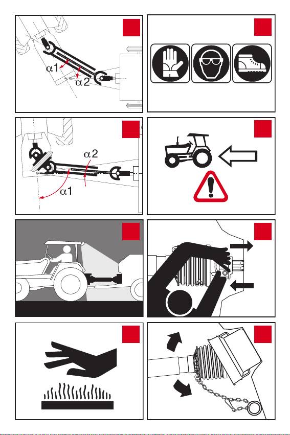
CARDAN JOINTS
12
When operating, ensure that joint angles are small and equal: a1 = a2.
During turns or other short duration maneuvers, the maximum recommended joint
angle is 45°. Disengage the PTO if the angles are too large or not identical.
CONSTANT VELOCITY JOINTS
13
For normal operations, it is best to keep the CV joint aligned or with the
smallest joint angle possible. During turns or other short duration maneuvers, the
maximum joint angle is 50°, 70° (Constant Velocity Joint 652) or 80° according to
the design of the CV joint. When the driveline includes a CV joint on the tractor side
and a single U-joint on the implement side, the maximum recommended angles of
-1
-1
the U-joint are 16° at 540 min
and 9° at 1000 min
to avoid drive irregularities.
16

ENG
When used at night or in poor visibility, illuminate the driveline operating
14
area.
Friction clutches may become hot during use. Do not touch! Keep the area
15
around the friction clutch clear of any material which could cause a fire and
avoid prolonged slipping of the clutch.
INSTALLATION
Always wear adequate safety equipment when performing any maintenance
16
or repair work.
The tractor stamped on the shield indicates the tractor end of the driveline.
17
Any torque limiter or overrunning clutch should always be installed on the
implement end.
Ensure that the driveline is securely attached to the tractor and the implement
18
before operating.
Check that all fixing screws are tight.
Attach the driveline guard restraints (chains). Best results are achieved when
19
chains are attached nearly perpendicular to the driveline guard. Adjust the
length of the chains to allow enough slack for full movement of the driveline during
turns, operation, and transport. Avoid excessive slack, which could cause the
chains to roll around the driveline.
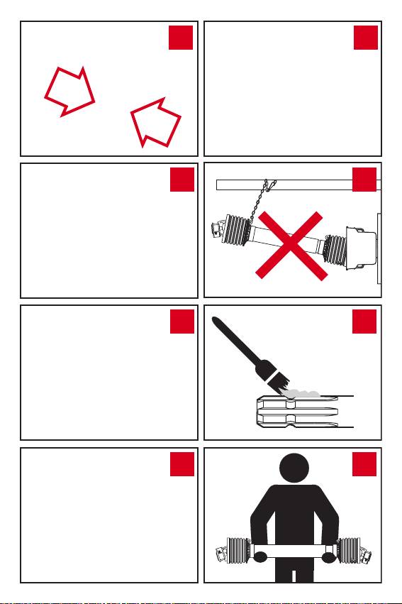
If the length of the chain is not adjusted correctly and tension is excessive,
20
for example during implement maneuvers, the “S” hook will detach from the
locking ring and the chain will disconnect from the shield.
In this case, the chain must be replaced.
The “S” hook of the new chain must be inserted in the eye of the base cone and
it must be closed to prevent it from becoming disengaged, maintaining its round
shape.
If the length of the chain with device for separation from the base cone is
21
not adjusted correctly and chain tension increases excessively, for example
during implement maneuvers, the spring hook will detach from the locking ring and
the chain will disconnect from the shield.
In this case, the chain is easily reconnected as described in the following procedure.
Open the retaining ring, unscrewing the screw and moving the plate.
22
Insert the chain in the locking ring and reposition the plate.
23
Close the plate by means of the screw.
24
Never use the safety chains to transport or support the driveline when you
25
have finished using it for storage. Always use the support provided on the
implement.
Clean and grease the tractor PTO and implement shaft before installing the
26
driveline.
Keep the driveline horizontal during handling to prevent the halves from
27
sliding apart, which could cause injury or damage the shielding. Use suitable
means to transport heavy drivelines.
17

ENG
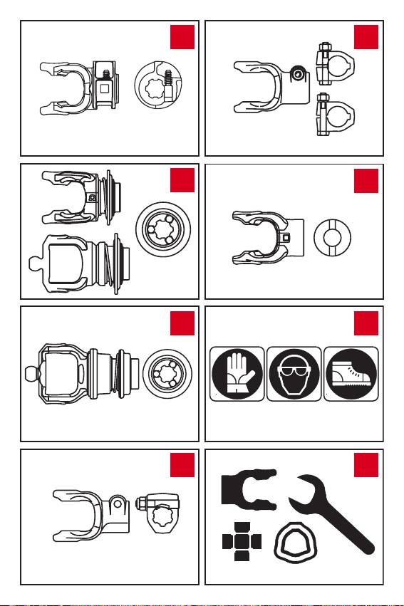
PUSH-PIN
28
Push the pin and slide the yoke onto the PTO shaft so that the pin engages
the groove on the PTO. Make sure that the pin returns to its initial position after
attachment to the shaft.
BALL COLLAR
29
Align the yoke on the PTO. Slide the collar to the open position. Slide the
yoke onto the splined shaft. Release the collar and pull or push the yoke along the
shaft until the balls engage the groove and the collar returns to its original (closed)
position. Make sure the collar returns to its initial (closed) position and the yoke is
properly attached to the shaft.
AUTOMATIC BALL COLLAR
30
Pull the collar back until it locks in the open position. Use both hands to slide
the yoke onto the shaft - the collar will automatically unlock. Push or pull the yoke
along the shaft until the balls engage the groove and the collar returns to its original
(closed) position. Make sure the collar returns to its initial (closed) position and the
yoke is properly attached to the shaft.
TAPER PIN
31
Slide the yoke onto the PTO and insert the pin so that the tapered profile fits
into the groove on the shaft.
Recommended tightening torque:
- 150 Nm (110 ft lbs) for 1 3/8” Z6 or Z21 spline.
- 220 Nm (160 ft lbs) for 1 3/4” Z6 or Z20 spline.
Use only Bondioli & Pavesi taper pins for replacements.
CLAMP BOLT
32
Slide the yoke onto the PTO and insert the bolt.
Recommended tightening torque: - 90 Nm (65 ft lbs) for M12 bolts;
- 140 Nm (100 ft lbs) for M14 bolts.
SHEAR PINS
33
Use only bolts of the size and class shown in the implement handbook.
Choose the bolt length in such a way as to minimize protrusion.
LUBRICATION
Always wear adequate safety equipment when performing any maintenance
34
or repair work.
Replace worn or damaged parts with genuine Bondioli & Pavesi spare parts.
35
Do not modify or tamper with any part of the driveline. For any operations not
explained in this instruction manual, consult your implement dealer or manufacturer,
or your local Bondioli & Pavesi representative.
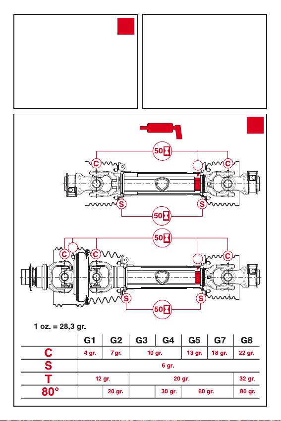
LUBRICATION OF TELESCOPING TUBES
36
If grease fittings are not provided, separate the two halves of the driveline,
and manually lubricate the telescoping tubes.
18

ENG
Check that all components are in good condition and properly lubricated
37
before using the driveline. Clean and lubricate the driveline at the end of
seasonal use. Lubricate each part after the number of hours shown on the chart.
The amounts of grease indicated in the manual are recommended for an interval of
50 hours. Particularly severe applications in an aggressive environment may
require lubrication more frequently than at 50-hour intervals.
Amounts indicated in grams (g). 1 ounce (oz.) = 28.3 g (grams).
Pump grease into the crosses until it purges from the bearing caps.
Inject the grease gradually and avoid pumping the grease gun violently with
resulting high delivery pressure. Use NLGI grade 2 grease.
Before storage at the end of the season remove any grease that has accumulated
inside the CV joint shield.
LUBRICATION OF THE 80° CONSTANT VELOCITY JOINT
38
Align the holes in the CV shield with the grease fittings of the crosses and of
the central body of the constant velocity joint. The grease injected into the body
of the constant velocity joint also lubricates the shield support ring through an
internal channel. Every 50 hours, inject at least the amount of grease indicated in
the table in point 37.
TORQUE LIMITER AND OVERRUNNING CLUTCH
RA - OVERRUNNING CLUTCH.
39
This device prevents transmission of inertial loads from implement to the
tractor during deceleration or stopping of the PTO.
Keep clear of the implement until all parts have stopped moving. Lubricate
every 50 hours of use and after storage.
SA - LN RATCHET TORQUE LIMITER.
40
This device interrupts the transmission of power when the torque exceeds
the setting.
Immediately disengage the PTO when ratcheting sounds are heard.
Lubricate every 50 hours of use and after storage.
LB – SHEAR BOLT TORQUE LIMITER.
41
This device interrupts the transmission of power by shearing a bolt when the
torque exceeds the setting.
Replace the sheared bolt with the same diameter, length and grade as the original.
Lubricate the LB limiters with grease fittings at least once every season and after a
period of disuse.
LR - AUTOMATIC TORQUE LIMITER
42
Interrupts power transmission when the torque exceeds the set value.
During the intervention of the device, power transmission is interrupted but it may
be automatically resumed by running the driveline at a low speed after having
removed the blockage.
This device is sealed - no additional lubrication is required.
GE – SHOCK ABSORBING CLUTCH
43
Absorbs shock loads and vibrations, and smoothes transmission of an
alternating or pulsating load. No maintenance is required.
19

ENG
FRICTION TORQUE LIMITERS
Check the condition of the friction linings when installing the clutch or after periods
of storage.
• If the edges of the clutch plates are exposed (see g. 44) the clutch is either type
FV with Belleville spring or FFV with helicoil springs. Measure and record the spring
height as shown in gure 45. If the clutch plates are covered by a metal band (see
gure 46) the clutch is type FT.
If the clutch discs are exposed and the bolts have cap nuts, the clutch is of
the FK type.
Following seasonal use, relieve the spring pressure and keep the clutch in a dry
place. Check the condition of friction disks and restore spring pressure before
using the clutch. If the clutch overheats due to frequent or prolonged slipping,
consult your equipment dealer or manufacturer, or your local Bondioli & Pavesi
representative.
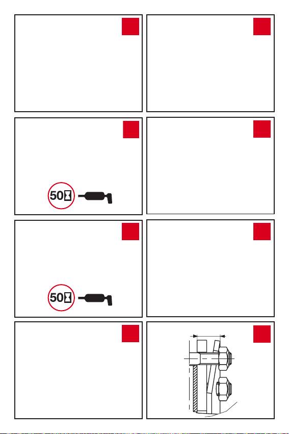
FV – FRICTION TORQUE LIMITER.
44
The torque transmitted to the implement is limited by allowing the clutch
plates to slip relative to each other. Torque peaks or short duration overloads are
limited when the clutch is used and adjusted properly.
It can be used as an overload clutch, or to help start implements with high inertial
loads.The torque setting is adjustable by adjusting the working height of the spring.
The edges of the linings and plates are exposed in an FV clutch.
The torque setting is adjusted by increasing or decreasing the height “h”
45
of the springs. To increase/decrease the torque setting tighten/loosen the
eight nuts by 1/4 of a turn and check for correct operation. Repeat the procedure if
necessary. Avoid excessive tightening of the bolts - implement, tractor, or driveline
damage may occur.
FT - FK FRICTION TORQUE LIMITERS
46
The torque transmitted to the machine is limited by allowing the clutch plates
to slip relative to each other. Torque peaks or short duration overloads are limited
when the clutch is used and adjusted properly. It can be used as an overload
clutch, or to help start implements with high inertial loads. The FT has a metal
band around its circumference. The bolts should be tightened until the metal band
around the circumference of the clutch touches the spring, then loosen each nut
by 1/4 turn. Avoid excessive tightening of the bolts - implement, tractor, or driveline
damage may occur.
The FK clutch has bolts with cap nuts. The spring compression is correct
when the nuts are fully screwed on. Use only special B&P bolts and nuts.
If the clutch has four socket head set screws in addition to the eight hex
47
head bolts on the ange yoke, it is equipped with the Spring Release system.
Spring pressure is relieved when these four set screws are screwed into the ange
yoke. See the instruction leaet enclosed with clutches with the Spring Release
system installed. The Spring Release System enables checking of the condition
of the friction clutch and reduces spring pressure on the disks during storage.
Friction clutches equipped with the Spring Release System are supplied with
an additional instruction sheet. Read this information for proper use of the
Spring Release System.
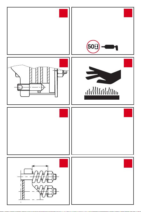
FFV - FRICTION TORQUE LIMITER
48
The torque transmitted to the implement is limited by allowing the clutch plates to
slip relative to each other. Torque peaks or short duration overloads are limited when the
clutch is used and adjusted properly. It can be used as an overload clutch, or to help start
20

ENG
implements with high inertial loads.The torque setting is adjustable by adjusting the working
height of the springs.The edges of the linings and plates are exposed in an FFV clutch.
The torque setting is adjusted by increasing or decreasing the height “h”
49
of the springs. To increase/decrease the torque setting tighten/loosen the
eight nuts by 1/4 of a turn and check for correct operation. Repeat the procedure if
necessary. Avoid excessive tightening of the bolts - implement, tractor, or driveline
damage may occur.
FNT - FNV - FFNV - FNK COMBINATION FRICTION AND OVERRUNNING
50
CLUTCH Clutch that combines the functional characteristics of a friction
clutch and an overrunning clutch. Used on machines with high inertial loads.
Keep clear of the implement until all parts have stopped moving.
Lubricate every 50 hours of use and after storage.
Friction clutches may become hot during use. Do not touch! To avoid the
51
risk of fire keep the area around the clutch free of inflammable material and
avoid prolonged slipping of the clutch.
SHIELD DISASSEMBLY
Remove the Philips head screws.
52
Remove the base cone and the shield tube.
53
Remove the outer cone and the bearing ring.
54
SHIELD ASSEMBLY
Grease the bearing groove on inner yokes.
55
Fit the bearing ring into the groove with the reference pin facing the drive
56
tube.
Fit the outer cone, inserting the reference pin of the bearing in the hole
57
provided in the cone.
Fit the base cone with the tube, inserting the reference pin and the grease
58
tting of the bearing in the holes provided in the cone.
Tighten the Philips head screws.
59
Use of electric powered screwdrivers is not recommended.
CV JOINT SHIELD DISASSEMBLY
Remove the screws arranged radially around the circumference of the CV
60
cone.
Remove the screws from the base cone.
61
Remove the base cone and the shield tube.
62
Remove the CV cone.
63
21

ENG
Disengage the retaining spring, leaving it inserted in one of the two holes of
64
the bearing ring to avoid losing it.
Spread the bearing rings and remove from their groove.
65
CV JOINT SHIELD ASSEMBLY
Grease the seats and install the shield support bearings.
66
Fit the bearing ring onto the inner yoke with the reference pin facing the
drive tube.
Install the bearing ring on the CV body with the reference pins facing the
67
inner yoke. The bearing ring is equipped with a grease tting, used only for
50° CV joints. This grease tting is not used with 80° CV joints.
Connect the retaining spring to the two edges of the bearing ring.
68
Insert the shield aligning the radial holes with the reference pins of the bearing
69
ring and the hole on the bottom with the reference pin of the small bearing.
The grease tting of the bearing must be aligned with the holes on the shield.
Check that the radial holes in the shield are aligned with the holes in the
70
reference pins of the bearing ring and that the reference pin is inserted.
Tighten the 6 anged screws of the shield. Use of an electric screwdriver is not
recommended.
Fit the base cone with the tube, inserting the reference pin of the bearing in
71
the hole provided in the base cone. The grease tting of the bearing is in the
hole of the base cone.
Tighten the 3 screws. Use of electric powered screwdrivers is not recommended.
72
HOW TO SHORTEN THE DRIVE SHAFT
Bondioli & Pavesi advises against altering its products. If modifications are required,
we recommend that you consult your implement dealer or a qualified service center
before proceeding. If the driveline is too long adopt the following procedure.
Remove the shielding.
73
Shorten the drive tubes by the required length.
74
Telescoping tubes must always overlap by at least 1/2 of their length in
normal operation and at least 1/3 of their length in all working conditions.
During maneuvers, when the driveline is not rotating, the telescoping tubes must
have a suitable overlap to maintain the tubes aligned and allow them to slide freely.
Carefully deburr the ends of the tubes with a file and remove all filings from
75
the tubes.
Shorten shield tubes one at time by cutting the same length that was cut
76
from the drive tubes.
22

ENG
Grease the internal drive tube and reassemble the shielding on the driveshaft.
77
Check the length of the driveshaft at its minimum and maximum extensions
78
on the implement.
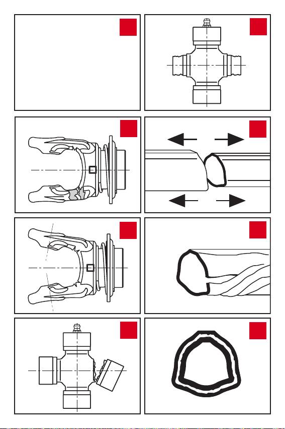
TROUBLESHOOTING
WEAR OF YOKE EARS
79
EXCESSIVE WORKING ANGLE
• Reduce the working angle.
• Disengage PTO when joint angle exceeds 45°.
DEFORMATION OF YOKES
80
EXCESSIVE TORQUE PEAK OR SHOCK LOAD
• Avoid overloading or engaging PTO when under load.
• Check the efficiency of the torque limiter.
CROSS ARM BROKEN
81
EXCESSIVE TORQUE PEAK OR SHOCK LOAD
• Avoid overloading or engaging PTO when under load.
• Check function of torque limiter.
ACCELERATED WEAR OF CROSS ARMS
82
EXCESSIVE LOAD
• Do not exceed the speed or power limits indicated in the instruction manual.
INSUFFICIENT LUBRICATION
• Follow instructions in point 37.
SEPARATION OF TELESCOPING TUBES
83
EXCESSIVE EXTENSION OF DRIVELINE
• Do not extend driveline to the point that the tubes separate.
• For stationary machinery, position the tractor so the telescoping tubes overlap
as illustrated in point 10.
TWISTING OR BENDING OF TELESCOPING TUBES
84
EXCESSIVE TORQUE PEAK OR SHOCK LOAD
• Avoid overloading or engaging PTO when under load
• Check the efficiency of the torque limiter.
• Check that driveline does not come into contact with tractor or implement
components during manoeuvres.
ACCELERATED WEAR OF TELESCOPING TUBES
85
INSUFFICIENT LUBRICATION
• Follow instructions in the chapter on Lubrication
INSUFFICIENT TUBE OVERLAP
• See instructions in point 10.
PREMATURE WEAR OF THE PROTECTIVE BEARINGS
86
INSUFFICIENT LUBRICATION
• Follow the instructions in point 37.
RESTRAINT CHAIN NOT CORRECTLY FIXED
• See instructions in point 19.
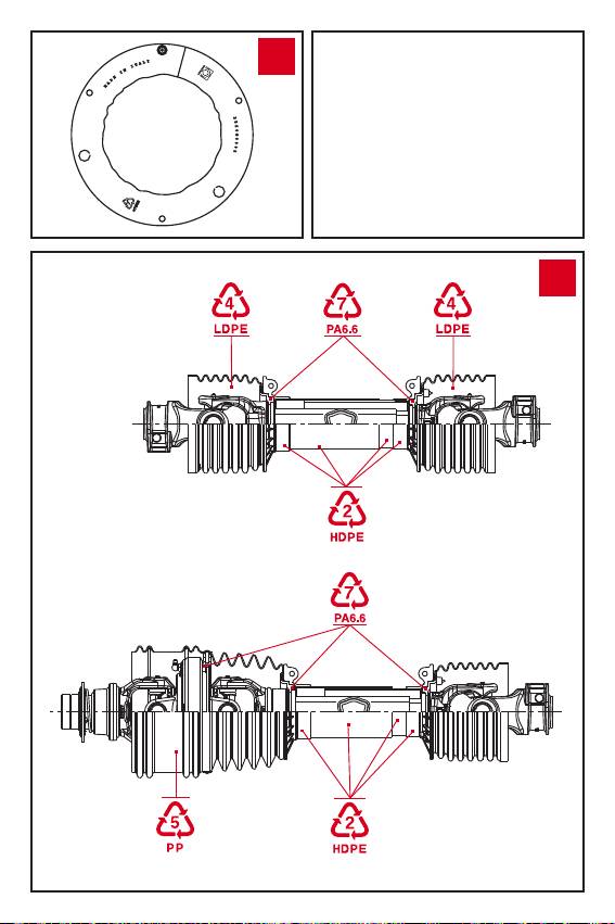
All the plastic parts of Bondioli & Pavesi drivelines are totally recyclable.
87
Protect the environment by disposing of used plastic parts properly at the
time of replacement.
23
