ASRock 990FX EXTREME3 – page 2
Manual for ASRock 990FX EXTREME3
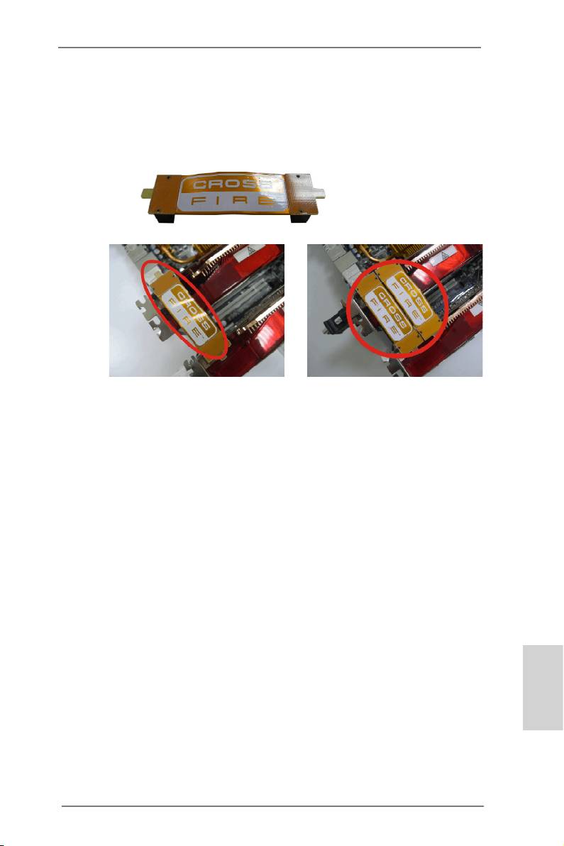
Step 2. Connect two Radeon graphics cards by installing CrossFire Bridge on
CrossFire Bridge Interconnects on the top of Radeon graphics cards.
(CrossFire Bridge is provided with the graphics card you purchase, not
bundled with this motherboard. Please refer to your graphics card vendor
for details.)
CrossFire Bridge
or
Step 3. Connect the DVI monitor cable to the DVI connector on the Radeon graph-
ics card in the PCIE2 slot. (You may use the DVI to D-Sub adapter to
convert the DVI connector to D-Sub interface, and then connect the D-Sub
monitor cable to the DVI to D-Sub adapter.)
English
21
ASRock 990FX Extreme3 Motherboard
TM
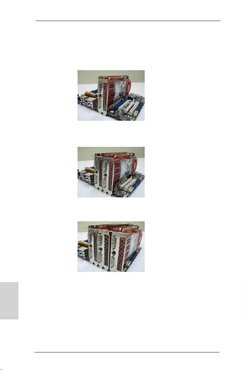
2.6.1.2 Installing Three CrossFireX
-Ready Graphics Cards
Step 1. Install one Radeon graphics card to the PCIE2 slot. For the proper instal-
lation procedures, please refer to section “Expansion Slots”.
Step 2. Install one Radeon graphics card to the PCIE3 slot. For the proper instal-
lation procedures, please refer to section “Expansion Slots”.
Step 3. Install one Radeon graphics card to the PCIE4 slot. For the proper instal-
lation procedures, please refer to section “Expansion Slots”.
TM
Step 4. Use one CrossFire
Bridge to connect Radeon graphics cards on PCIE2
English
TM
and PCIE3 slots, and use the other CrossFire
Bridge to connect Radeon
TM
graphics cards on PCIE3 and PCIE4 slots. (CrossFire
Bridge is provided
with the graphics card you purchase, not bundled with this motherboard.
Please refer to your graphics card vendor for details.)
22
ASRock 990FX Extreme3 Motherboard
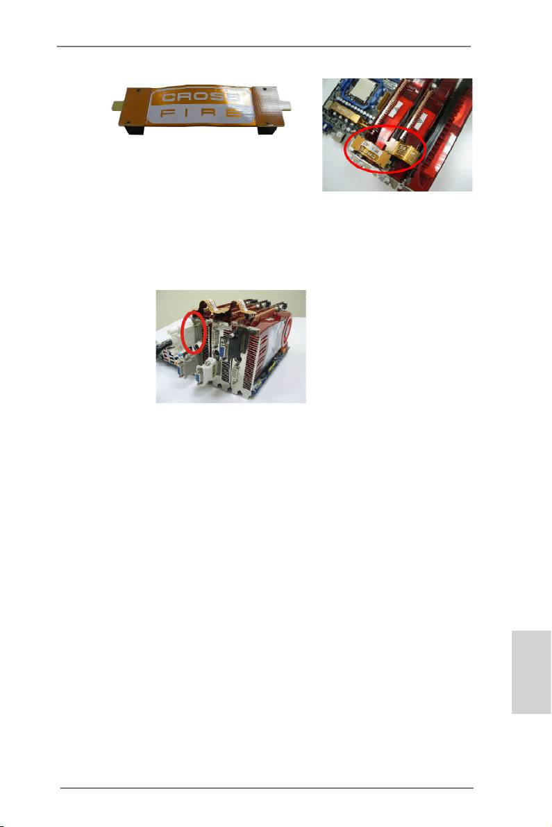
TM
CrossFire
Bridge
Step 5. Connect the DVI monitor cable to the DVI connector on the Radeon graph-
ics card in the PCIE2 slot. (You may use the DVI to D-Sub adapter to
convert the DVI connector to D-Sub interface, and then connect the D-Sub
monitor cable to the DVI to D-Sub adapter.)
English
23
ASRock 990FX Extreme3 Motherboard
2.6.2 Driver Installation and Setup
Step 1. Power on your computer and boot into OS.
TM
Step 2. Remove the ATI
driver if you have any VGA drivers installed in your sys-
tem.
The Catalyst Uninstaller is an optional download. We recommend using this
utility to uninstall any previously installed Catalyst drivers prior to installation.
TM
Please check AMD website for ATI
driver updates.
Step 3. Install the required drivers to your system.
®
For Windows
XP OS:
TM
®
A. AMD
recommends Windows
XP Service Pack 2 or higher to be
®
installed (If you have Windows
XP Service Pack 2 or higher installed
in your system, there is no need to download it again):
http://www.microsoft.com/windowsxp/sp2/default.mspx
B. You must have Microsoft .NET Framework installed prior to
downloading and installing the CATALYST Control Center. Please
check Microsoft website for details.
®
TM
For Windows
7 / Vista
OS:
Install the CATALYST Control Center. Please check AMD website for de-
tails.
Step 4. Restart your computer.
Step 5. Install the VGA card drivers to your system, and restart your computer.
®
Then you will nd “ATI Catalyst Control Center” on your Windows
taskbar.
ATI Catalyst Control Center
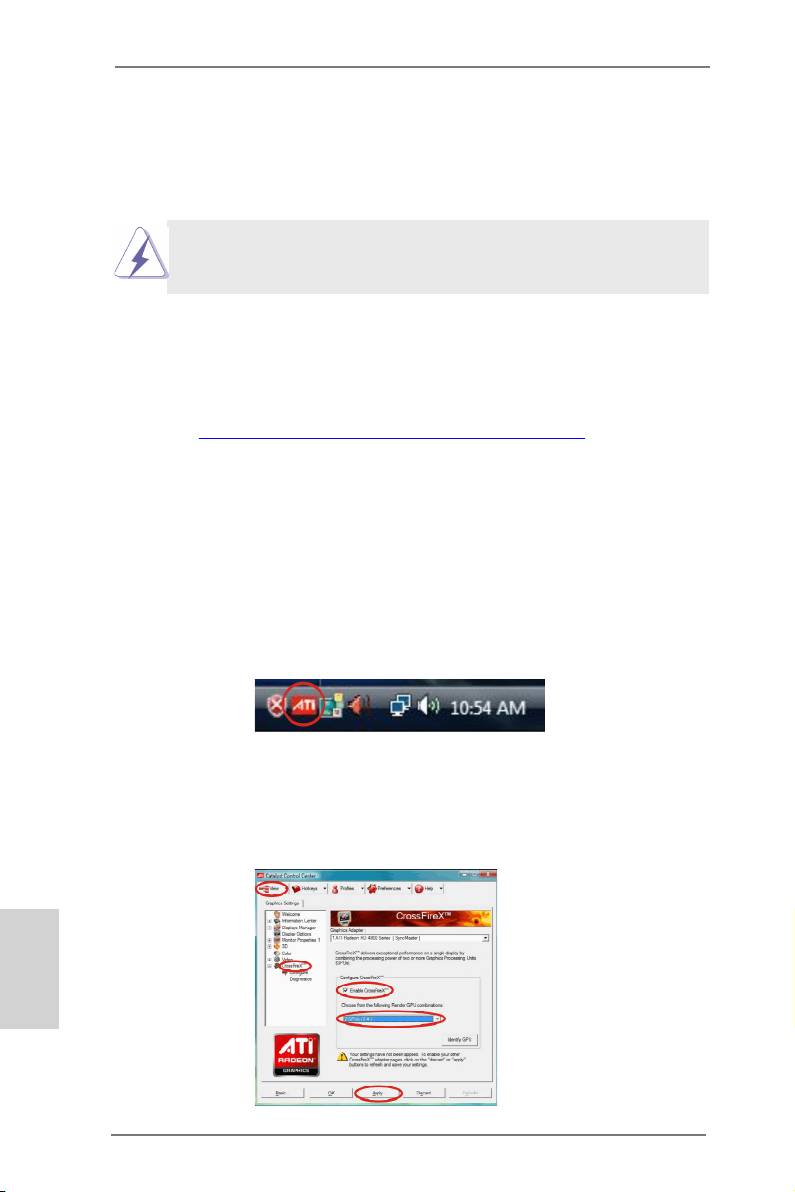
Step 6. Double-click “ATI Catalyst Control Center”. Click “View”, select “CrossFi-
TM
TM
reX
”, and then check the item “Enable CrossFireX
”. Select “2 GPUs”
and click “Apply” (if you installed two Radeon graphics cards). Select “3
GPUs” and click “OK” (if you installed three Radeon graphics cards).
English
24
ASRock 990FX Extreme3 Motherboard

TM
Although you have selected the option “Enable CrossFire
”, the CrossFi-
TM
reX
function may not work immediately. Your computer will automatically
reboot. After restarting your computer, please conrm whether the option
TM
“Enable CrossFire
” in “ATI Catalyst Control Center” is selected or not; if
not, please select it again, and then you are able to enjoy the benets of
TM
CrossFireX
features.
TM
TM
Step 7. You can freely enjoy the benets of CrossFireX
, 3-Way CrossFireX
or
TM
Quad CrossFireX
features.
TM
TM
* CrossFireX
appearing here is a registered trademark of AMD
Technologies Inc., and is
used only for identication or explanation and to the owners’ benet, without intent to infringe.
TM
TM
* For further information of AMD
CrossFireX
technology, please check AMD website for
updates and details.
2.7 Surround Display Feature
This motherboard supports Surround Display upgrade. With the external add-on PCI
Express VGA cards, you can easily enjoy the benets of Surround Display feature.
For the detailed instruction, please refer to the document at the following path in the
Support CD:
..\ Surround Display Information
English
25
ASRock 990FX Extreme3 Motherboard
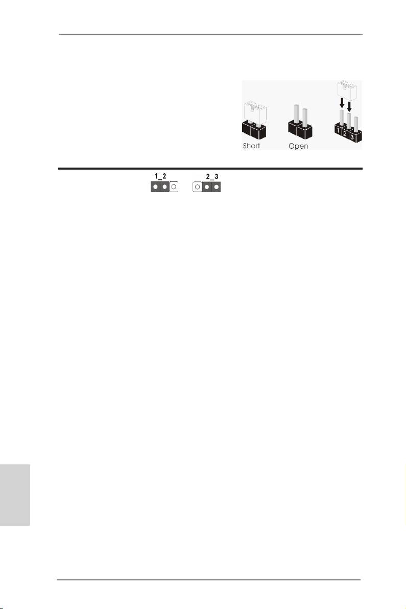
2.8 Jumpers Setup
The illustration shows how jumpers are
setup. When the jumper cap is placed on
pins, the jumper is “Short”. If no jumper cap
is placed on pins, the jumper is “Open”. The
illustration shows a 3-pin jumper whose
pin1 and pin2 are “Short” when jumper cap
is placed on these 2 pins.
Jumper Setting
Clear CMOS Jumper
(CLRCMOS1)
(see p.2, No. 22)
Clear CMOSDefault
Note: CLRCMOS1 allows you to clear the data in CMOS. The data in CMOS in-
cludes system setup information such as system password, date, time, and
system setup parameters. To clear and reset the system parameters to de-
fault setup, please turn off the computer and unplug the power cord from the
power supply. After waiting for 15 seconds, use a jumper cap to short pin2
and pin3 on CLRCMOS1 for 5 seconds. However, please do not clear the
CMOS right after you update the BIOS. If you need to clear the CMOS when
you just nished updating the BIOS, you must boot up the system rst, and
then shut it down before you do the clear-CMOS action. Please be noted that
the password, date, time, user default prole, 1394 GUID and MAC address
will be cleared only if the CMOS battery is removed.
English
26
ASRock 990FX Extreme3 Motherboard
2.9 Onboard Headers and Connectors
Onboard headers and connectors are NOT jumpers. Do NOT place
jumper caps over these headers and connectors. Placing jumper caps
over the headers and connectors will cause permanent damage of the
motherboard!
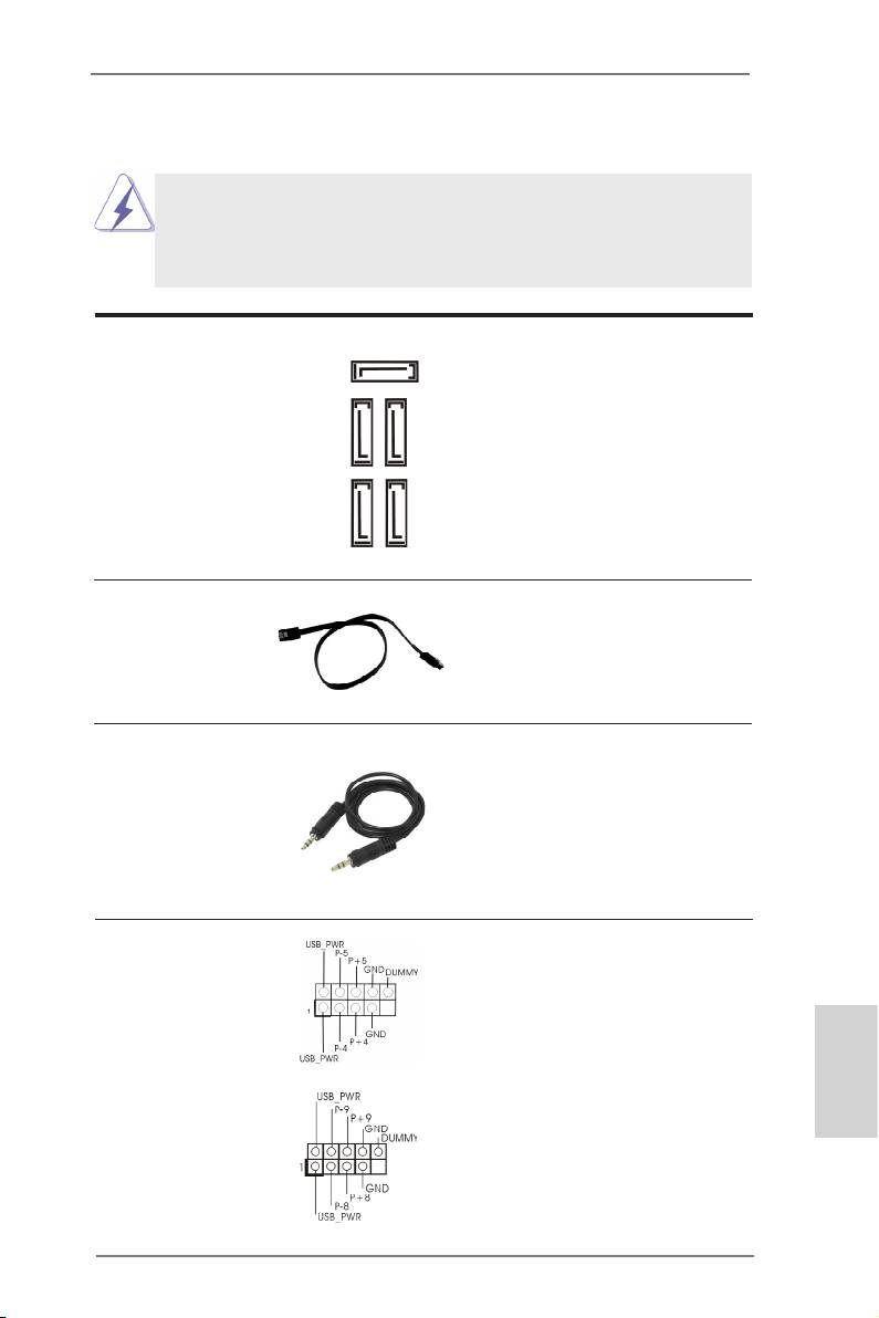
Serial ATA3 Connectors These ve Serial ATA3
SATA3_5
(SATA3_1_2: see p.2, No. 14)
(SATA3) connectors support
(SATA3_3_4: see p.2, No. 13)
SATA data cables for internal
(SATA3_5: see p.2, No. 12)
storage devices. The current
SATA3 interface allows up to
6.0 Gb/s data transfer rate.
SATA3_1_2 SATA3_3_4
Serial ATA (SATA) Either end of the SATA data
Data Cable cable can be connected to the
(Optional)
SATA3 hard disk or the SATA3
connector on this motherboard.
3.5mm Audio Cable Either end of the 3.5mm audio
(Optional)
cable can be connected to the
portable audio devices, such
as MP3 player and mobile
phone or the Line-in port of
your PC.
USB 2.0 Headers Besides six default USB 2.0
(9-pin USB4_5)
ports on the I/O panel, there
(see p.2 No. 23)
are three USB 2.0 headers on
this motherboard. Each USB 2.0
header can support two USB
2.0 ports.
(9-pin USB8_9)
English
(see p.2 No. 24)
27
ASRock 990FX Extreme3 Motherboard
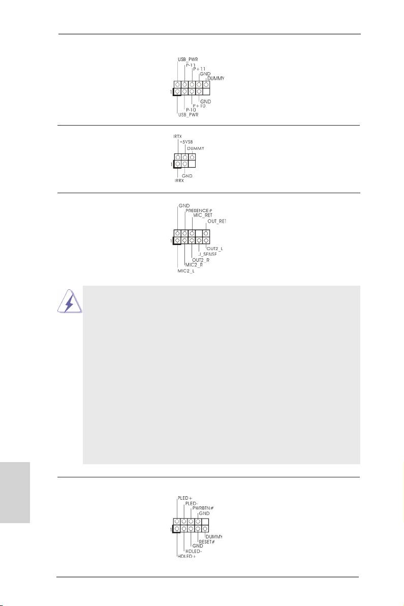
(9-pin USB10_11)
(see p.2 No. 25)
Infrared Module Header This header supports an
(5-pin IR1)
optional wireless transmitting
(see p.2 No. 27)
and receiving infrared module.
Front Panel Audio Header This is an interface for the front
(9-pin HD_AUDIO1)
panel audio cable that allows
(see p.2 No. 28)
convenient connection and
control of audio devices.
1. High Denition Audio supports Jack Sensing, but the panel wire on
the chassis must support HDA to function correctly. Please follow the
instructions in our manual and chassis manual to install your system.
2. If you use an AC’97 audio panel, please install it to the front panel audio
header as below:
A. Connect Mic_IN (MIC) to MIC2_L.
B. Connect Audio_R (RIN) to OUT2_R and Audio_L (LIN) to OUT2_L.
C. Connect Ground (GND) to Ground (GND).
D. MIC_RET and OUT_RET are for HD audio panel only. You don’t
need to connect them for AC’97 audio panel.
E. To activate the front mic.
®
For Windows
XP / XP 64-bit OS:
Select “Mixer”. Select “Recorder”. Then click “FrontMic”.
®
TM
TM
For Windows
7 / 7 64-bit / Vista
/ Vista
64-bit OS:
Go to the "FrontMic" Tab in the Realtek Control panel. Adjust
“Recording Volume”.
English
System Panel Header This header accommodates
(9-pin PANEL1)
several system front panel
(see p.2 No. 19)
functions.
28
ASRock 990FX Extreme3 Motherboard
Connect the power switch, reset switch and system status indicator
on the chassis to this header according to the pin assignments below.
Note the positive and negative pins before connecting the cables.
PWRBTN (Power Switch):
Connect to the power switch on the chassis front panel. You may con-
gure the way to turn off your system using the power switch.
RESET (Reset Switch):
Connect to the reset switch on the chassis front panel. Press the reset
switch to restart the computer if the computer freezes and fails to per-
form a normal restart.
PLED (System Power LED):
Connect to the power status indicator on the chassis front panel. The
LED is on when the system is operating. The LED keeps blinking
when the sys-tem is in S1 sleep state. The LED is off when the system
is in S3/S4 sleep state or powered off (S5).
HDLED (Hard Drive Activity LED):
Connect to the hard drive activity LED on the chassis front panel. The
LED is on when the hard drive is reading or writing data.
The front panel design may differ by chassis. A front panel module
mainly consists of a power switch, reset switch, power LED, hard drive
activity LED, speaker and etc. When connecting your chassis front
panel module to this header, make sure the wire assignments and the
pin assign-ments are matched correctly.
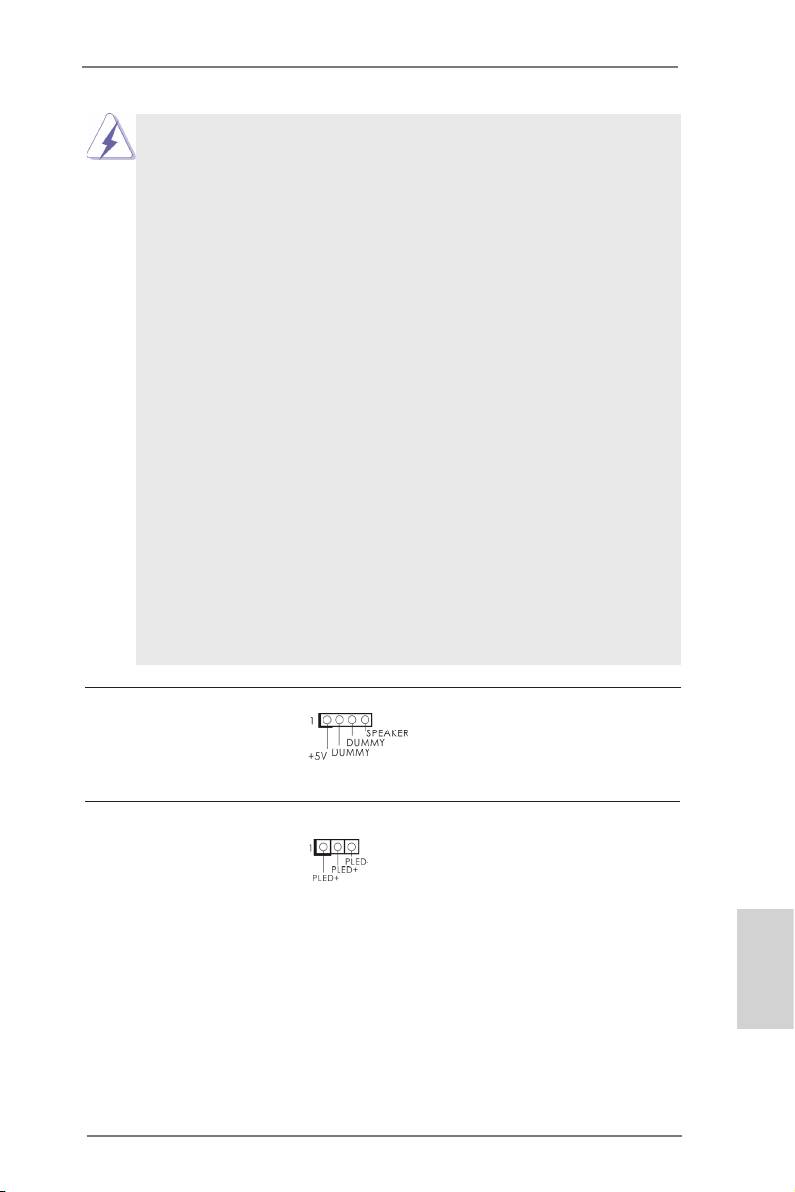
Chassis Speaker Header Please connect the chassis
(4-pin SPEAKER 1)
speaker to this header.
(see p.2 No. 18)
Power LED Header Please connect the chassis
(3-pin PLED1)
power LED to this header to
(see p.2 No. 17)
indicate system power status.
The LED is on when the system
is operating. The LED keeps
blinking in S1 state. The LED is
off in S3/S4 state or S5 state
(power off).
English
29
ASRock 990FX Extreme3 Motherboard
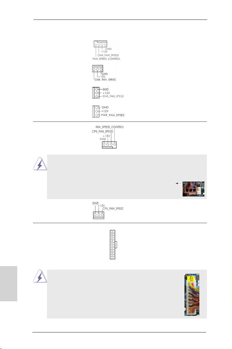
Chassis and Power Fan Connectors Please connect the fan cables
(4-pin CHA_FAN1)
to the fan connectors and
(see p.2 No. 21)
match the black wire to the
ground pin. CHA_FAN1/2/3 fan
(3-pin CHA_FAN2)
speed can be controlled through
(see p.2 No. 20)
UEFI or AXTU.
(3-pin CHA_FAN3)
(see p.2 No. 10)
(3-pin PWR_FAN1)
(see p.2 No. 35)
CPU Fan Connectors Please connect the CPU fan
(4-pin CPU_FAN1)
cable to the connector and
(see p.2 No. 4)
match the black wire to the
ground pin.
1 2 3 4
Though this motherboard provides 4-Pin CPU fan (Quiet Fan) support, the 3-Pin
CPU fan still can work successfully even without the fan speed control function.
If you plan to connect the 3-Pin CPU fan to the CPU fan connector on this
motherboard, please connect it to Pin 1-3.
Pin 1-3 Connected
3-Pin Fan Installation
(3-pin CPU_FAN2)
(see p.2 No. 5)
ATX Power Connector Please connect an ATX power
12
24
(24-pin ATXPWR1)
supply to this connector.
(see p.2 No. 9)
1
13
English
Though this motherboard provides 24-pin ATX power connector,
12
24
it can still work if you adopt a traditional 20-pin ATX power supply.
To use the 20-pin ATX power supply, please plug your power
supply along with Pin 1 and Pin 13.
20-Pin ATX Power Supply Installation
1
13
30
ASRock 990FX Extreme3 Motherboard

ATX 12V Power Connector Please connect an ATX 12V
5 1
(8-pin ATX12V1)
power supply to this connector.
8 4
(see p.2 No. 2)
Though this motherboard provides 8-pin ATX 12V power connector, it can still work
if you adopt a traditional 4-pin ATX 12V power supply. To use the 4-pin ATX power
supply, please plug your power supply along with Pin 1 and Pin 5.
5 1
4-Pin ATX 12V Power Supply Installation
8 4
Serial port Header This COM1 header supports a
(9-pin COM1)
serial port module.
(see p.2 No.26)
HDMI_SPDIF Header HDMI_SPDIF header, providing
(2-pin HDMI_SPDIF1)
SPDIF audio output to HDMI
(
see p.2 No. 1)
VGA card, allows the system to
connect HDMI Digital TV/
projector/LCD devices. Please
connect the HDMI_SPDIF
connector of HDMI VGA card to
this header.
English
31
ASRock 990FX Extreme3 Motherboard

2.10 Driver Installation Guide
To install the drivers to your system, please insert the support CD to your optical
drive rst. Then, the drivers compatible to your system can be auto-detected and
listed on the support CD driver page. Please follow the order from up to bottom side
to install those required drivers. Therefore, the drivers you install can work properly.
®
TM
2.11 Installing Windows
7 / 7 64-bit / Vista
/
TM
Vista
64-bit / XP / XP 64-bit With RAID Functions
®
TM
TM
If you want to install Windows
7 / 7 64-bit / Vista
/ Vista
64-bit / XP / XP 64-
bit on your SATA3 HDDs with RAID functions, please refer to the document at the
following path in the Support CD for detailed procedures:
..\ RAID Installation Guide
®
TM
2.12 Installing Windows
7 / 7 64-bit / Vista
/
TM
Vista
64-bit / XP / XP 64-bit Without RAID Functions
®
TM
TM
If you want to install Windows
7 / 7 64-bit / Vista
/ Vista
64-bit / XP / XP 64-bit
OS on your SATA3 HDDs without RAID functions, please follow below procedures
according to the OS you install.
®
2.12.1 Installing Windows
XP / XP 64-bit Without RAID
Functions
®
If you want to install Windows
XP / XP 64-bit on your SATA3 HDDs without RAID
functions, please follow below steps.
Using SATA3 HDDs without NCQ and Hot Plug functions (IDE mode)
STEP 1: Set up UEFI.
A.Enter UEFI SETUP UTILITY Advanced screen Storage Conguration.
B.Set the option “SATA Mode” to [IDE].
®
STEP 2: Install Windows
XP / XP 64-bit OS on your system.
English
32
ASRock 990FX Extreme3 Motherboard

®
TM
TM
2.12.2 Installing Windows
7 / 7 64-bit / Vista
/ Vista
64-bit
Without RAID Functions
®
TM
TM
If you want to install Windows
7 / 7 64-bit / Vista
/ Vista
64-bit on your SATA3
HDDs without RAID functions, please follow below steps.
Using SATA3 HDDs without NCQ and Hot Plug functions (IDE mode)
STEP 1: Set up UEFI.
A.Enter UEFI SETUP UTILITY Advanced screen Storage Conguration.
B.Set the option “SATA Mode” to [IDE].
®
TM
TM
STEP 2: Install Windows
7 / 7 64-bit / Vista
/ Vista
64-bit OS on your sys-
tem.
Using SATA3 HDDs with NCQ and Hot Plug functions (AHCI mode)
STEP 1: Set up UEFI.
A.Enter UEFI SETUP UTILITY Advanced screen Storage Conguration.
B.Set the option “SATA Mode” to [AHCI].
®
TM
TM
STEP 2: Install Windows
7 / 7 64-bit / Vista
/ Vista
64-bit OS on your
system.
2.13 Untied Overclocking Technology
This motherboard supports Untied Overclocking Technology, which means during
overclocking, FSB enjoys better margin due to xed PCI / PCIE buses. Before you
enable Untied Overclocking function, please enter “Overclock Mode” option of UEFI
setup to set the selection from [Auto] to [Manual]. Therefore, CPU FSB is untied
during overclocking, but PCI / PCIE buses are in the xed mode so that FSB can
operate under a more stable overclocking environment.
Please refer to the warning on page 9 for the possible overclocking risk
before you apply Untied Overclocking Technology.
English
33
ASRock 990FX Extreme3 Motherboard

3. BIOS Information
The Flash Memory on the motherboard stores BIOS Setup Utility. When you start up
the computer, please press <F2> or <Del> during the Power-On-Self-Test (POST)
to enter BIOS Setup utility; otherwise, POST continues with its test routines. If you
wish to enter BIOS Setup after POST, please restart the system by pressing <Ctl>
+ <Alt> + <Delete>, or pressing the reset button on the system chassis. The BIOS
Setup program is designed to be user-friendly. It is a menu-driven program, which
allows you to scroll through its various sub-menus and to select among the prede-
termined choices. For the detailed information about BIOS Setup, please refer to the
User Manual (PDF le) contained in the Support CD.
4. Software Support CD information
®
®
This motherboard supports various Microsoft
Windows
operating systems: 7 / 7
TM
TM
64-bit / Vista
/ Vista
64-bit / XP / XP 64-bit. The Support CD that came with the
motherboard contains necessary drivers and useful utilities that will enhance moth-
erboard features. To begin using the Support CD, insert the CD into your CD-ROM
drive. It will display the Main Menu automatically if “AUTORUN” is enabled in your
computer. If the Main Menu does not appear automatically, locate and double-click
on the le “ASSETUP.EXE” from the BIN folder in the Support CD to display the
menus.
English
34
ASRock 990FX Extreme3 Motherboard

1. Einführung
Wir danken Ihnen für den Kauf des ASRock 990FX Extreme3 Motherboard, ein zu-
verlässiges Produkt, welches unter den ständigen, strengen Qualitätskontrollen von
ASRock gefertigt wurde. Es bietet Ihnen exzellente Leistung und robustes Design,
gemäß der Verpflichtung von ASRock zu Qualität und Halbarkeit. Diese Schnel-
linstallationsanleitung führt in das Motherboard und die schrittweise Installation
ein. Details über das Motherboard nden Sie in der Bedienungsanleitung auf der
Support-CD.
Da sich Motherboard-Spezikationen und BIOS-Software verändern
können, kann der Inhalt dieses Handbuches ebenfalls jederzeit geändert
werden. Für den Fall, dass sich Änderungen an diesem Handbuch
ergeben, wird eine neue Version auf der ASRock-Website, ohne weitere
Ankündigung, verfügbar sein. Die neuesten Grakkarten und unterstützten
CPUs sind auch auf der ASRock-Website aufgelistet.
ASRock-Website: http://www.asrock.com
Wenn Sie technische Unterstützung zu Ihrem Motherboard oder spezische
Informationen zu Ihrem Modell benötigen, besuchen Sie bitte unsere
Webseite: www.asrock.com/support/index.asp
1.1 Kartoninhalt
ASRock 990FX Extreme3 Motherboard
(ATX-Formfaktor: 30.5 cm x 21.8 cm; 12.0 Zoll x 8.6 Zoll)
ASRock 990FX Extreme3 Schnellinstallationsanleitung
ASRock 990FX Extreme3 Support-CD
Ein ASRock SLI_Bridge_2S-Karte
Zwei Serial ATA (SATA) -Datenkabel (optional)
Ein Audiokabel (3,5 mm, Klinke) (optional)
Ein I/O Shield
ASRock erinnert...
®
TM
TM
Zur besseren Leistung unter Windows
7 / 7, 64 Bit / Vista
/ Vista
64 Bit empfehlen wir, die Speicherkonguration im BIOS auf den AHCI-
Modus einzustellen. Hinweise zu den BIOS-Einstellungen nden Sie in
der Bedienungsanleitung auf der mitgelieferten CD.
Deutsch
35
ASRock 990FX Extreme3 Motherboard

1.2 Spezifikationen
Plattform - ATX-Formfaktor: 30.5 cm x 21.8 cm; 12.0 Zoll x 8.6 Zoll
- Alle Feste Kondensatordesign (100% in Japan gefertigte,
erstklassige leitfähige Polymer-Kondensatoren)
CPU - Unterstützung von Socket AM3+-Prozessoren
- Unterstützung von Socket AM3-Prozessoren: AMD Phenom
TM
II X6 / X4 / X3 / X2 (außer 920 / 940) / Athlon X4 / X3 / X2
/ Sempron-Prozessor
- Acht-Kern-CPU-bereit
- Unterstützt UCC (Unlock CPU Core) (siehe VORSICHT 1)
- 4 + 1-Stromphasendesign
- Unterstützt CPU bis 140W
TM
- Unterstützt Cool ‘n’ Quiet
-Technologie von AMD
- FSB 2600 MHz (5.2 GT/s)
- Unterstützt Untied-Übertaktungstechnologie
(siehe VORSICHT 2)
- Unterstützt Hyper-Transport- 3.0 Technologie (HT 3.0)
Chipsatz - Northbridge: AMD 990FX
- Southbridge: AMD SB950
Speicher - Unterstützung von Dual-Kanal-Speichertechnologie
(siehe VORSICHT 3)
- 4 x Steckplätze für DDR3
- Unterstützt DDR3 2100(OC)/1866/1600/1333/1066/800
non-ECC, ungepufferter Speicher
(siehe VORSICHT 4)
- Max. Kapazität des Systemspeichers: 32GB
(siehe VORSICHT 5)
Erweiterungs- - 3 x PCI-Express-2.0-x16-Steckplätze
Steckplätze (PCIE2/PCIE3: x16-Modus; PCIE4: x4-Modus)
- 1 x PCI Express 2.0 x1-Steckplätze
- 2 x PCI -Steckplätze
TM
TM
TM
- Unterstützt AMD
Quad CrossFireX
, 3-Way CrossFireX
TM
Deutsch
und CrossFireX
®
TM
TM
- NVIDIA
Quad SLI
und SLI
Audio - 7.1
CH HD Audio mit dem Inhalt Schutz
(Realtek ALC892 Audio Codec)
- Premium Blu-ray-Audio-Unterstützung
36
ASRock 990FX Extreme3 Motherboard

LAN - PCIE x1 Gigabit LAN 10/100/1000 Mb/s
- Broadcom BCM57781
- Unterstützt Wake-On-LAN
- Unterstützt energieefzientes Ethernet 802.3az
- Unterstützt PXE
E/A-Anschlüsse I/O Panel
an der - 1 x PS/2-Mausanschluss
Rückseite - 1 x PS/2-Tastaturanschluss
- 1 x Koaxial-SPDIF-Ausgang
- 1 x optischer SPDIF-Ausgang
- 6 x Standard-USB 2.0-Anschlüsse
- 2 x Standard-USB 3.0-Anschlüsse
- 1 x eSATA3-Anschluss
- 1 x RJ-45 LAN Port mit LED (ACT/LINK LED und SPEED
LED)
- HD Audiobuchse: Lautsprecher seitlich / Lautsprecher
hinten / Mitte/Bass / Audioeingang/ Lautsprecher vorne /
Mikrofon (siehe VORSICHT 6)
SATA3 - 5 x SATA 3-Anschluss mit 6,0 Gb/s, unterstützt RAID-
(RAID 0, RAID 1, RAID 5 und RAID 10), NCQ-,
AHCI- und „Hot Plugging“-Funktionen
USB3.0 - 2 x USB 3.0-Ports an der Rückseite durch Etron EJ168A,
unterstützt USB 1.0/2.0/3.0 mit bis zu 5 Gb/s
Anschlüsse - 5 x SATA3 6,0 GB/s-Anschlüsse
- 1 x Infrarot-Modul-Header
- 1 x COM-Anschluss-Header
- 1 x HDMI_SPDIF-Anschluss
- 1 x Betriebs-LED-Header
- CPU/Gehäuse/Stromlüfter-Anschluss
- 24-pin ATX-Netz-Header
- 8-pin anschluss für 12V-ATX-Netzteil
- Anschluss für Audio auf der Gehäusevorderseite
- 3 x USB 2.0-Anschlüsse (Unterstützung 6 zusätzlicher
USB 2.0-Anschlüsse)
BIOS - 32Mb AMIs Legal BIOS UEFI mit GUI-Unterstützung
- Unterstützung für “Plug and Play”
- ACPI 1.1-Weckfunktionen
Deutsch
- JumperFree-Modus
- SMBIOS 2.3.1
- CPU, VCCM, NB, SB Stromspannung Multianpassung
37
ASRock 990FX Extreme3 Motherboard

Support-CD - Treiber, Dienstprogramme, Antivirussoftware (Probeversion),
CyberLink MediaEspresso 6.5-Testversion
Einzigartige - ASRock Extreme Tuning Utility (AXTU)
Eigenschaft (siehe VORSICHT 7)
- ASRock Sofortstart
- ASRock Instant Flash (siehe VORSICHT 8)
- ASRock APP Charger (siehe VORSICHT 9)
- ASRock XFast USB (siehe VORSICHT 10)
- ASRock XFast LAN (siehe VORSICHT 11)
- ASRock ein/aus-Wiedergabetechnologie
(siehe VORSICHT 12)
- Hybrid Booster:
- Schrittloser CPU-Frequenz-Kontrolle
(siehe VORSICHT 13)
- ASRock U-COP (siehe VORSICHT 14)
- Boot Failure Guard (B.F.G. – Systemstartfehlerschutz)
- Turbo 50 / Turbo 60 CPU Übertaktungs
- Turbo UCC
Hardware Monitor - CPU-Temperatursensor
- Motherboardtemperaturerkennung
- Drehzahlmessung für CPU/Gehäuse/Stromlüfter
- CPU-Lüftergeräuschdämpfung
- Mehrstuge Geschwindigkeitsteuerung für CPU-/
Gehäuselüfter
- Spannungsüberwachung: +12V, +5V, +3.3V, Vcore
®
®
TM
Betriebssysteme - Unterstützt Microsoft
Windows
7 / 7 64-Bit / Vista
/
TM
Vista
64-Bit / XP / XP 64-Bit
Zertizierungen - FCC, CE, WHQL
- Gemäß Ökodesign-Richtlinie (ErP/EuP) (Stromversorgung
gemäß Ökodesign-Richtlinie (ErP/EuP) erforderlich)
(siehe VORSICHT 15)
* Für die ausführliche Produktinformation, besuchen Sie bitte unsere Website:
http://www.asrock.com
Deutsch
38
ASRock 990FX Extreme3 Motherboard

WARNUNG
Beachten Sie bitte, dass Overclocking, einschließlich der Einstellung im BIOS, Anwenden
der Untied Overclocking-Technologie oder Verwenden von Overclocking-Werkzeugen von
Dritten, mit einem gewissen Risiko behaftet ist. Overclocking kann sich nachteilig auf die
Stabilität Ihres Systems auswirken oder sogar Komponenten und Geräte Ihres Systems
beschädigen. Es geschieht dann auf eigene Gefahr und auf Ihre Kosten. Wir übernehmen
keine Verantwortung für mögliche Schäden, die aufgrund von Overclocking verursacht wur-
den.
VORSICHT!
1. Die ASRock UCC-Funktion (Unlock CPU Core; zu Deutsch: CPU-Kern
freigeben) vereinfacht die AMD-CPU-Aktivierung. Zur Freigabe des zusätzli-
chen CPU-Kerns müssen Sie lediglich die UEFI-Option „Unlock CPU Core“
(zu Deutsch: CPU-Kern freigeben) umschalten – schon protieren Sie von
einem Leistungsschub. Wenn die UCC-Funktion aktiviert ist, rüstet die Dual-
Core- oder Triple-Core-CPU auf eine Quad-Core-CPU auf – einige CPUs
(inklusive Quad-Core) können zudem die L3-Cache-Größe auf bis zu 6 MB
anheben; das bedeutet verbesserte CPU-Leistung zu einem geringeren
Preis. Bitte beachten Sie, dass die UCC-Funktion nur bei AM3-CPUs ein-
setzbar ist; die Unterstützung besteht jedoch aufgrund möglicher Fehlfunk-
tionen des verborgenen Kerns einiger CPUs auch nicht zwangsläug bei
jeder AM3-CPU.
2. Dieses Motherboard unterstützt die Untied-Übertaktungstechnologie. Unter
“Entkoppelte Übertaktungstechnologie” auf Seite 33 nden Sie detaillierte
Informationen.
3.
Dieses Motherboard unterstützt Dual-Kanal-Speichertechnologie. Vor
Implementierung der Dual-Kanal-Speichertechnologie müssen Sie die
Installationsanleitung für die Speichermodule auf Seite 14 zwecks richtiger
Installation gelesen haben.
4. Ob die Speichergeschwindigkeit 2100 MHz unterstützt wird, hängt von
der von Ihnen eingesetzten AM3/AM3+-CPU ab. Schauen Sie bitte auf
unseren Internetseiten in der Liste mit unterstützten Speichermodulen
nach, wenn Sie DDR3 2100-Speichermodule einsetzen möchten. AM3+
CPU unterstützt DDR3 1866 ohne Übertaktung (OC Mode).
ASRock-Internetseite: http://www.asrock.com
5. Durch Betriebssystem-Einschränkungen kann die tatsächliche Speicher-
®
größe weniger als 4 GB betragen, da unter Windows
7 / Vista™ / XP
etwas Speicher zur Nutzung durch das System reserviert wird. Unter
®
Windows
OS mit 64-Bit-CPU besteht diese Einschränkung nicht.
6. Der Mikrofoneingang dieses Motherboards unterstützt Stereo- und Mono-
Modi. Der Audioausgang dieses Motherboards unterstützt 2-Kanal-,
Deutsch
4-Kanal-, 6-Kanal- und 8-Kanal-Modi. Stellen Sie die richtige Verbindung
anhand der Tabelle auf Seite 3 her.
7. ASRock Extreme Tuning Utility (AXTU) ist ein Alles-in-einem-Werkzeug
zur Feineinstellung verschiedener Systemfunktionen an einer benutzer-
freundlichen Schnittstelle; diese beinhaltet Hardware Überwachung,
39
ASRock 990FX Extreme3 Motherboard

Lüftersteuerung, Übertaktung, OC DNA und IES. Über die Hardware-
Überwachung können Sie die Hauptsystemdaten einsehen. Die
Lüftersteuerung zeigt Ihnen zur Anpassung Lüftergeschwindigkeit und
Temperatur an. Bei der Übertaktung können Sie die CPU-Frequenz zur
Erzielung optimaler Systemleistung übertakten. OC DNA ermöglicht
Ihnen die Speicherung Ihrer OC- Einstellungen als Pro l, welches Sie
mit Freunden teilen können. Ihre Freunde können das OC-Pro l dann
in ihrem System laden und so die gleichen OC-Einstellungen erzielen.
Per IES (Intelligent Energy Saver) kann der Spannungsregulator bei
Inaktivität der CPU-Kerne die Anzahl an Ausgangsphasen zur Steigerung
der Ef zienz reduzieren – ohne die Rechenleistung zu beeinträchtigen.
Hinweise zur Bedienung der ASRock Extreme Tuning Utility (AXTU)
nden Sie auf unserer Webseite.
ASRock-Webseite: http://www.asrock.com
8. ASRock Instant Flash ist ein im Flash-ROM eingebettetes BIOS-Flash-
Programm. Mithilfe dieses praktischen BIOS-Aktualisierungswerkzeugs
können Sie das System-BIOS aktualisieren, ohne dafür zuerst Betriebs-
®
systeme wie MS-DOS oder Windows
aufrufen zu müssen. Mit diesem
Programm bekommen Sie durch Drücken der <F6>-Taste während des
POST-Vorgangs oder durch Drücken der <F2>-Taste im BIOS-Setup-
Menü Zugang zu ASRock Instant Flash. Sie brauchen dieses Werkzeug
einfach nur zu starten und die neue BIOS-Datei auf Ihrem USB-Flash-
Laufwerk, Diskettenlaufwerk oder der Festplatte zu speichern, und schon
können Sie Ihr BIOS mit nur wenigen Klickvorgängen ohne Bereitstellung
einer zusätzlichen Diskette oder eines anderen komplizierten Flash-Pro-
gramms aktualisieren. Achten Sie darauf, dass das USB-Flash-Laufwerk
oder die Festplatte das Dateisystem FAT32/16/12 benutzen muss.
9. Wenn Sie nach einer schnelleren, weniger eingeschränkten Möglich-
keit zur Auadung Ihrer Apple-Geräte (z. B. iPhone/iPad/iPod touch)
suchen, bietet ASRock Ihnen eine wunderbare Lösung – den ASRock
APP Charger. Installieren Sie einfach den ASRock APP Charger-Treiber;
dadurch lädt sich Ihr iPhone wesentlich schneller über einen Computer
auf – genaugenommen bis zu 40 % schneller als zuvor. Der ASRock APP
Charger ermöglicht Ihnen die schnelle Auadung mehrerer Apple-Geräte
gleichzeitig; der Ladevorgang wird sogar dann fortgesetzt, wenn der PC
den Ruhezustand (S1), Suspend to RAM-Modus (S3) oder Tiefschlafmo-
dus (S4) aufruft oder ausgeschaltet wird (S5). Nach der Installation des
APP Charger-Treibers können Sie im Handumdrehen das großartigste
Deutsch
Ladeerlebnis überhaupt genießen.
ASRock-Webseite: http://www.asrock.com/Feature/AppCharger/index.
asp
10. ASRocks XFast USB dient der Steigerung der Leistungsfähigkeit Ihrer
USB-Speichergeräte. Die Leistung kann je nach Eigenschaften des Gerä-
tes variieren.
11. ASRock XFast LAN bietet einen schnelleren Internetzugang mit den
nachfolgenden Vorteilen. LAN-Anwendungspriorisierung: Hiermit kon-
gurieren Sie auf ideale Weise Ihre Anwendungspriorität und/oder fügen
40
ASRock 990FX Extreme3 Motherboard


