Jet Tools C30: AB
AB: Jet Tools C30
6.
NORME DI FUNZIONAMENTO • OPERATING PROCEDURES
ENGLISH
ITALIANO
– 118 –
024_057_0.tif
14
A B
6.4.3
Uso corretto delle lame
circolari
Assicurarsi che la macchina sia
ben piazzata in modo da evitare
dannose vibrazioni.
Evitare di ritirare il materiale quan-
do il taglio è già iniziato; procedere
con un avanzamento continuo
senza strappi.
La velocità di avanzamento del
pezzo contro la lama, special-
mente in corrispondenza dei nodi,
non deve essere veloce e deve
essere rapportata allo spessore
dello stesso.
Non fare sostare i pezzi fra guida
sega e lama
Rimuovere sempre i rifi li che si
creano durante la lavorazione in
quanto potrebbero inserirsi fra
la lama e il copriforo creando
danni alla macchina o pericolo per
l'operatore.
Prima di eseguire la rimozione
spegnere la macchina e attendere
che la lama sega sia ferma.
Non urtare le placchette contro
oggetti metallici.
Quando i taglienti perdono il fi lo,
riaffi lare subito la lama.
Pulire spesso il corpo d’acciaio e
le placchette dalle incrostazioni
usando gli appositi liquidi in com-
mercio. Lasciare a bagno la lama,
poi pulire con spazzola vegetale.
Non usare spazzole metalliche.
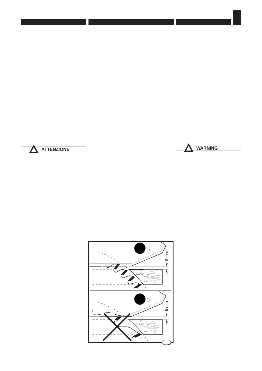
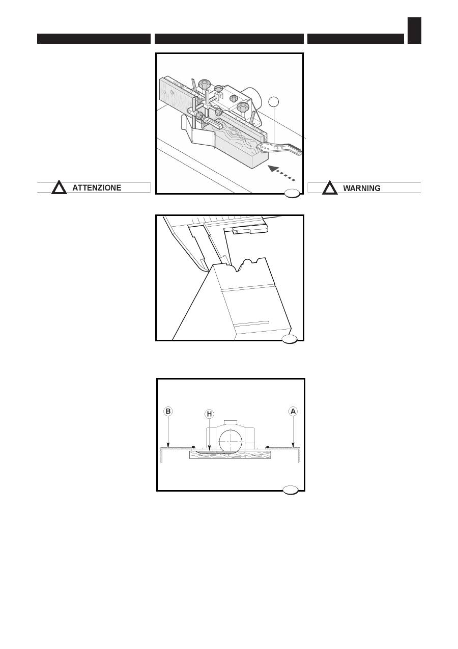
Scegliere la dentatura ricordando
che per avere un buon taglio è ne-
cessario che almeno 2-3 taglienti
lavorino nello stesso tempo
A
(fi g. 14). Se lavora un solo tagliente
B
(fi g.14) non si ottiene un buon
taglio.
È inoltre importante, quando è
possibile, sollevare la lama fi no a
fare sporgere dallo spessore del
legno tutto il tagliente del dente.
6.4.3 Correct use for circular
saw
First make sure that the machine
does not vibrate.
Do not try to take off the material
when the cut has already started;
proceed with a continuous and
uniform speed.
Workpiece feeding towards the
blade (especially where there
are knots) should not be too fast
(feeding speed should be in accor-
dance with workpiece thickness).
Do not let workpieces stop betwe-
en the saw fence and the blade.
Always remove any trimmings
produced during machining
because trimmings interposed
between the blade and the hole
covers might damage the machine
or be a source of danger for the
operator.
Turn off the machine and wait for
the cutting blade to stop before
removing.
Avoid contact of the tips against
metallic objects.
When necessary sharpen the saw
blade.
Often clean the steel body and the
tips with proper liquid products.
Let the saw blade in the bath,
then clean it with brush: don’t use
metallic brushes.
As regards the toothing at least
2-3 teeth shall cut at the same time
A
(fi g. 14).
If only one tooth cuts
B
(fi g. 14) you
don’t get a good cutting.
Whenever this is possible, it is
also critical to lift the blade until the
whole tooth cutting part protrudes
from the wood thickness.
- 119 -
РАБОЧИЕ ПРОЦЕДУРЫ • NORMES POUR LE FONCTIONNEMENT
NORMAS DE FUNCIONAMIENTO
FRANÇAIS
РУССКИЙ
ESPAÑOL
6.
6.4.3 Правильное
использование дисковой
пилы
Во избежание вредных вибраций
у б ед и т ь с я в п р а в и л ь н о с т и
установки станка.
Не отводить заготовку, когда
процесс распила уже был начат.
Подавать заготовку с постоянной
скоростью, без рывков.
Скорость подачи заготовки на пилу,
в особенности, в местах сучков, не
должна быть слишком высокой.
Скорость подачи выбирается с
учетом толщины заготовки.
Н е з а д е р ж и в ат ь з а гот о в к и
в п р о с т р а н с т в е м е ж д у
н а п р а вл я ю ще й л и н е й к о й и
пильным диском.
Убирать обрезки, образующиеся
в процессе раскроя - они могут
попасть в промежуток между
пилой и крышкой, что создаст
проблемы для работы станка и
угрозу для здоровья оператора.
Перед началом процедуры
по извлечению обрезков
отключить станок и дождаться
остановки пилы.
Избегать соударения режущих
н а п а е к с м е т а л л и ч е с к и м и
предметами.
При затуплении режущих элементов
немедленно заточить пилу.
Регулярно очищать стальной диск
и напайки пилы от отложений,
используя доступные в продаже
с п е ц и а л ь н ы е о ч и щ а ю щ и е
жидкости. Сначала замочить пилу
в жидкости, затем, очистить ее
щеткой с растительным ворсом. Не
использовать металлических щеток.
При выборе числа зубьев пилы
исходить из того принципа, что для
качественного реза необходимо,
чтобы одновременно работали не
менее 2-3 резцов A (рис. 14). При
работе лишь одного резца B (рис.14)
качество реза не будет высоким.
П р и в о з м о ж н о с т и н а д л е ж и т
установить пилу на такую высоту,
чтобы в верхнем положении резец
зуба полностью выступал над
заготовкой.
6.4.3 Utilisation correcte des
lames
S’assurer de la bonne stabilité de la
machine, afi n d’éviter toutes vibra-
tions.
Eviter d’enlever le matériau lorsque le
sciage est en cours; l’avance doit être
continue et exempte d’àcoup.
La vitesse d’avance de la pièce con-
tre la lame, pariculièrement sur les
noeuds, doit être modérée et com-
parée à l’épaisseur la pièce-même.
Ne jamais écarter les pièces entre
guide scie et lame.
Toujours enlever les ébarbures
formées pendant l’usinage, car
elles pourraient s’introduire entre
lame et dispositif de couverture
du trou, ce qui endommagerait la
machine ou créerait des situations
de danger pour l’opérateur.
Avant d'effectuer le retrait, éteindre
la machine et attendre l'arrêt
complet de la lame.
Les plaquettes ne doivent jamais
venir en contact avec des objets
métalliques. Lorsque les arrêtes
tranchantes perdent le fi l, réaffûter
im-médiatement la lame.
Débarasser la lame d’acier et les
plaquettes des incrustations avec
des dissolvants vendus en com-
merce. Laisser tremper la lame et
la nettoyer à l’aide d’une brosse
végétale. Ne jamais utiliser de bros-
se métallique.
Choisir la denture en tenant compte
que pour obtenir un bon sciage au
moin 2-3 tranchants doivent travailler
simultanément
A
(fi g. 14).
Si seule una arête tranchante tra-
vaille
B
(fi g. 14) la coupe n’est pas
bonne.
Il est aussi important, lorsque possi-
ble, de soulever la lame jusqu’à faire
sortir de l’epaisseur du bois tout le
tranchant de la dent.
6.4.3 Uso correcto de las hojas
circulares
Asegurarse de que la máquina esté
posicionada correctamente, con el fi n
de evitar vibraciones peligrosas.
Evitar el retiro del material durante
la operación de corte; es necesariò
seguir con un avance continuo sin
tirones.
La velocidad de avance de la pieza
contra la hoja, especialmente donde
se hallan los nudos, no debe ser
veloz, ni debe depender del espesor
de la pieza.
No dejar las piezas detenidas entre
la guía sierra y la hoja.
Eliminar siempre los recortes que
se forman durante el trabajo, ya que
podrían colocarse entre la hoja y la
protección del agujero causando
daños a la máquina o situaciones de
peligro para el operador.
Antes de retirar los paneles es
necesario apagar la máquina
y esperar que la sierra se haya
detenido.
No chocar las placas con objetos
metálicos.
Cuando los fi los cortantes pierden el
hilo, reafi lar inmediatamente la hoja.
Limpiar a menudo las incrustaciones
del cuerpo de acero y de las placas
empleando los líquidos disponibles en
comercio. Dejar la hoja en el líquido,
luego limpiar con una escobilla vegetal.
No utilizar escobillas de alambre.
Durante la elección del dentado, recor-
dar que con el fi n de obtener un corte
correcto, es necesario el trabajo de 2-3
fi los cortantes a la vez
A
(fi g. 14).En
caso de trabajo de un sólo fi lo cortante
B
(fi g. 14), el corte no será perfecto.
Además es muy importante, cuando
sea posible, elevar la hoja hasta
cuando toda la parte cortante del
diente sobresale desde el espesor
de la madera.
ВНИМАНИЕ
6.
NORME DI FUNZIONAMENTO • OPERATING PROCEDURES
ENGLISH
ITALIANO
– 120 –
040_077_0.tif
15
6.5.
LAVORAZIONI ALLA
TOUPIE
Con l’albero toupie si eseguono
operazioni di:
- Tenonatura (OPT)
- Sbattentatura
- Sagomatura (OPT)
- Profi latura
Smontare la protezione sega e
abbassare completamente la lama
sotto il piano.
Montare sempre la protezione
toupie idonea per la lavorazione
da eseguire, come indicato nei
paragrafi che seguono.
E' vietato montare utensili con
diametro superiore a quello
indicato nel cap.2.
Prima di abbassare l'utensile
sotto al piano assicurarsi sempre
che il suo diametro sia massimo
150 mm (UENSILE MASSIMO
RIENTRANTE SOTTO AL PIANO Ø
150 X 35).
Le lavorazioni con la cuffi a
guida toupie devono essere
eseguite tenendo i due piani di
appoggio il più chiusi possibile
per evitare che l'utensile si
trascini il pezzo.
Prima di procedere alla
lavorazione registrare la cuffi a
toupie e i pressatori come
indicato nel cap.5.
Quando si eseguono lavori
ripetitivi o di esecuzione
particolare si consiglia di crearsi
una controguida da fi ssare
alla cuffi a toupie, aprendola in
corrispondenza dell'utensile.
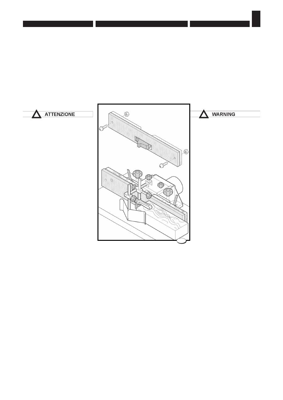
La controguida deve essere
fi ssata ai due piani di appoggio
mediante 2 viti testa bombata e 2
dadi M8 (fi g.15).
6.5. WORKING WITH MOUL-
DER UNIT
With the moulder it is possible to
carry out the following operations:
- Tenoning (OPT)
- Rabbeting
- Shaping (OPT)
- Profi ling
Disassemble the saw protection
and completely lower the blade
underneath the table.
Always mount the router guard
suited to the machining operation
to be carried out, as indicated in
the following paragraphs.
It is prohibited to mount tools with
a diameter greater than indicated
in Chap. 2.
Before lowering the tool under
the table, always ensure that its
maximum diameter is 150 mm
(TOOL MAXIMUM INDENTURE
UNDER TABLE Ø 150 X 35).
Machining with the router fence
hood should be carried out while
keeping the two support tables in
their closest possible position, to
prevent the tool from carrying the
workpiece along.
Before proceeding with
machining, adjust the router hood
and the pressers as indicated in
Chap. 5.
When repetitive or special
operations must be carried out,
it is recommended to make a
counterfence to be applied to the
router hood, opened to let the tool
through.
The counterguide must be
secured to the two tables by
means of the 2 convex-head
screws and 2 m8 nuts (fi g. 15).

- 121 -
РАБОЧИЕ ПРОЦЕДУРЫ • NORMES POUR LE FONCTIONNEMENT
NORMAS DE FUNCIONAMIENTO
FRANÇAIS
РУССКИЙ
ESPAÑOL
6.
6.5. РАБОТА НА ФРЕЗЕРНОМ
УЗЛЕ
На фрезерном узле станк а
возможно выполнение следующих
операций:
- Нарезка шипов (OPT)
- Обгонка
- Криволинейное фрезерование
по шаблону (OPT)
- П р од ол ь н о е п р о ф и л ь н о е
фрезерование
Для работы демонтировать
пильное ограждение и полностью
опустить пилу под стол.
Каждый раз устанавливать
ограждение шпинделя,
соответствующее выполняемой
операции, как указано в
следующих параграфах.
Не использовать инструменты
с диаметром, превышающим
значение, указанное в главе 2.
Перед тем как опускать
инструмент под стол убедиться,
что его диаметр не превосходит
150 мм (МАКСИМАЛЬНЫЕ
РАЗМЕРЫ ИНСТРУМЕНТА,
УБИРАЕМОГО ПОД СТОЛ - Ø150 X
35).
При обработке с использованием
направляющих линеек
устанавливать линейки как можно
ближе друг к другу - так, чтобы
инструмент не мог увлечь за
собой заготовку.
Перед началом работы
отрегулировать ограждение
шпинделя и прижимы, как указано
в главе 5.
В случае выполнения
повторяющихся или особых
операций рекомендуется
изготовить дополнительную
накладную линейку с вырезом в
месте нахождения инструмента.
Накладная линейка крепится
к основным линейкам двумя
винтами с полукруглой головкой
и гайками M8 (рис. 15).
6.5. TRAVAIL AVEC TOUPIE
Avec l’arbre toupie on peut exécuter
les opérations suivantes:
- Ténonnage (OPT)
- Chantournement
- Façonnage (OPT)
- Profi lage
- Ponçage
Démonter la protection scie et
descendre complètement la lame
sous le plateau.
Toujours monter la protection
toupie adaptée au travail à exécuter,
comme indiqué aux paragraphes
suivants.
Il est interdit de monter des outils
ayant un diamètre supérieur à celui
indiqué au chap.2.
Avant d’abaisser l’outil en dessous
du plan, toujours vérifi er si son
diamètre est de maximum 150
mm (OUTIL MAXI RENTRANT EN
DESSOUS DU PLAN Ø 150 X 35).
Les usinages avec protecteur guide
toupie doivent être effectués en
gardant les deux surfaces d’appui
les plus fermés possible pour éviter
que l’outil entraîne la pièce.
Avant d’effectuer l’usinage régler la
protection toupie et les presseurs
comme indiqué au chapitre 5.
Lorsqu’on effectue des travaux
répétitifs ou demandant une
exécution particulière, il est
conseillé de créer un contre-guide
à fi xer au protecteur toupie, en
l’ouvrant à la hauteur de l’outil.
Le contre-guide doit être fi xè aux
deux plans d'appui au moyen des
deux vis a tête bombêe et des deux
êcrous M8 (fi g. 15).
6.5. TRABAJOS EN LA TUPÍ
Mediante el árbol tupí se efectúan
las operaciones de:
- Ensamble de espiga y caja (OPT)
- Perfi ladura exterior
- Perfi lado (OPT)
- Perfi ladura
Desmontar la protección de la sierra
y hacer descender completamente
la cuchilla debajo del plano.
Monte siempre la guía de la
buriladora correspondiente a la
operación de máquina que se va a
realizar, tal y como se indica en los
siguientes párrafos.
Se prohibe montar herramientas de
diámetro superior al indicado en el
cap. 2.
Antes de bajar la herramienta por
debajo de la superfi cie asegurarse
siempre de que su diámetro sea
máximo 150 mm (HERRAMIENTA
MÁXIMA REENTRANTE DEBAJO DE
LA MESA Ø 150 X 35).
Cualquier trabajo con la envoltura
guía tupí se debe efectuar
manteniendo los dos planos de
apoyo cerrados lo más posible, con
el fi n de evitar que la herramienta
arrastre la pieza.
Antes de proceder a la elaboración,
calibrar la protección tupí y las
prensas como se indica en el cap. 5.
En caso de trabajos repetitivos o
particulares, se aconseja preparar
una contra guía a sujetar sobre el
cabezal tupí, abriéndola donde se
halla la herramienta.
La contraguia debe fi jarse a las
dos superfi cies de apoyo mediante
2 tornillos de cabeza curva y 2
tuercas M8 (fi g. 15).
ВНИМАНИЕ
6.
NORME DI FUNZIONAMENTO • OPERATING PROCEDURES
ENGLISH
ITALIANO
– 122 –
40_071_0.tif
16
040_060_1.tif
17
C
E
C
D
D
F
A
18
63_067_0.tif
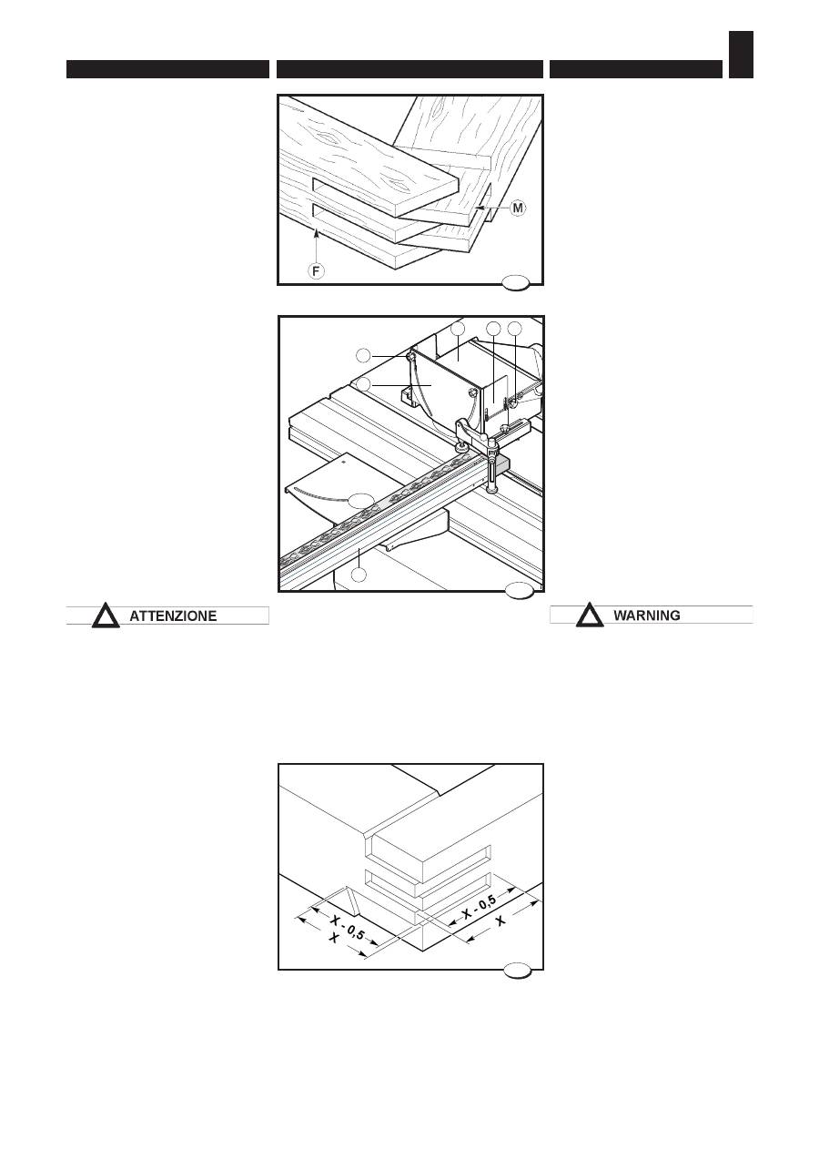
Tenonatura
La tenonatura è una fresatura di
testa (a traverso di vena) che vie-
ne effettuata per ottenere incastri
fra tenone maschio
M
(fi g. 16) e
tenone femmina
F
.
Eseguire questa operazione con
il carro scorrevole, montando
l’apposito pianetto a tenonare
(fi g. 17) e predisponendo la guida
A
con il paraschegge come indi-
cato nel paragrafo 4.3.6.
Utilizzare l'apposita cuffia per
tenonare
C
.
Agire sui pomelli
D
e regolare le
protezioni
E
e
F
in modo da coprire
al massimo l'utensile.
Bloccare sempre il pezzo
utilizzando il pressore in
dotazione.
La lavorazione di tenonatura va
eseguita esclusivamente con la
velocità di rotazione dell'albero
di 4250 giri/min.
Per un migliore assemblaggio nello
strettoio occorre:
– regolare la profondità dei tenoni
maschio 0,5 mm inferiori alla
larghezza del montante (fi g. 18);
– regolare la profondità dei tenoni
femmina 0,5 mm inferiori alla
larghezza del traverso (fi g. 18).
Tenoning
Tenoning is a head milling ope-
ration (against the grain) which is
carried out to obtain joints between
male tenons
M
(Fig. 16) and female
tenons
F
.
Perform this operation using the
sliding carriage, fi tting the appro-
priate tenoning table (fi g. 17) and
positioning fence
A
with the chip
shield as shown in section 4.3.6.
Use the appropriate tenoning
hood
C
.
Act on the knobs
D
and adjust the
protections
E
and
F
so that they
cover the tool as much as possible.
Always lock the piece using the
presser provided.
Tenoning must exclusively be
carried out with a spindle rotation
speed of 4250 rpm.
For a better assembly:
– adjust the tenon depth 0,5 mm
less than the jamb width (fi g. 18);
– adjust the slot depth 0,5 mm
less than the crosspiece width
(fi g. 18).

- 123 -
РАБОЧИЕ ПРОЦЕДУРЫ • NORMES POUR LE FONCTIONNEMENT
NORMAS DE FUNCIONAMIENTO
FRANÇAIS
РУССКИЙ
ESPAÑOL
6.
Нарезка шипов
Нарезка шипов - это операция
фрезерования торца брусковой
детали (поперек волокон) для
формирования шипов M (рис.16)
и проушин F.
Для выполнения этой операции
н а д л е ж и т и с п о л ь з о в а т ь
каретку с установленным на
н е й ш и п о р ез н ы м с т ол и к о м
(рис.17). При этом линейка A
с противоскольной пластиной
должна быть установлена, как
указано в параграфе 4.3.6.
Использовать специальный кожух
C для нарезки шипов.
Ослабив барашковые винты D
отрегулировать ограждения E и
F так, чтобы они максимально
закрывали инструмент.
Всегда закреплять заготовку
прилагаемым прижимом.
Нарезка шипов должна
выполняться только на скорости
вращения шпинделя 4250 об/мин.
Д л я п о в ы ш е н и я к ач ес т ва
сборки конструкции в вайме
рекомендуется
– настроить глубину проушин на
поперечном элементе рамы
на 0,5 мм меньше ширины
в е р т и к а л ь н о г о э л е м е н т а
(рис.18);
– настроить глубину проушин на
вертикальном элементе рамы
на 0,5 мм меньше ширины
поперечного элемента (рис.18).
Ténonnage
Le tenonnage est un fraisage de tête
(en travers le la veine) qui doit être
effectué pour obtenir des encastre-
ments entre tenon mâle
M
(fi g. 16)
et tenon femelle
F
.
Effectuer cette opération avec le
chariot mobile, en montant la tablette
de tenonnage prévue à cet effet (fi g.
17) et en plaçant le guide
A
avec
le pare-éclats comme l'indique la
rubrique 4.3.5.
Utiliser le protecteur à tenonner
C
approprié.
Agir sur les pommeaux
D
et régler
les protections
E
et
F
de manière à
recouvrir l’outil au maximum.
Bloquer toujours la pièce en
utilisant le presseur fourni en
équipement.
Le tenonnage doit être effectué
exclusivement avec la vitesse de
rotation de l’arbre à
4250 tours/min.
Pour faciliter l’assemblage:
– régler la profondeur du ténon 0,5
mm. inférieure à la largeur du
montant (fi g.18);
– régler la profondeur de la mortaise
0,5 mm. inférieure à la largeur de
la 1.ère traverse (fi g. 18).
Ensamble de espiga y caja
Sacar espigas es una operación de
fresado principal (contra el grano)
que se realiza para obtener articula-
ciones entre espigas macho
M
(fi g.
16) y espigas hembra
F
.
Efectuar esta operación con el carro
deslizante, instalado en la mesa de
espigado (fi g. 17) y preparando la
guía
A
con el protector contra astillas
como indica el párrafo 4.3.5.
Usar la apropiada envoltura para
ensamblar
C
.
Servirse de las perillas
D
y regular
las protecciones
E
y
F
para cubrir la
herramienta lo máximo posible.
Bloquear siempre la pieza utilizando
la prensa que se entrega con la
máquina.
El espigado debe ser efectuado
exclusivamente con una velocidad
de rotación del árbol de 4250 rev/
min.
Para un mejor montaje en la
prensa, hacer lo siguiente:
– regular la profundidad de las espi-
gas macho 0,5 mm inferiores a la
anchura del montante (fi g. 18);
– regular la profundidad de las espi-
gas hembra 0,5 mm inferiores a la
anchura del través (fi g. 18).
ВНИМАНИЕ
6.
NORME DI FUNZIONAMENTO • OPERATING PROCEDURES
ENGLISH
ITALIANO
– 124 –
10_005.tif
19
029_025_0.tif
20
Sbattentatura
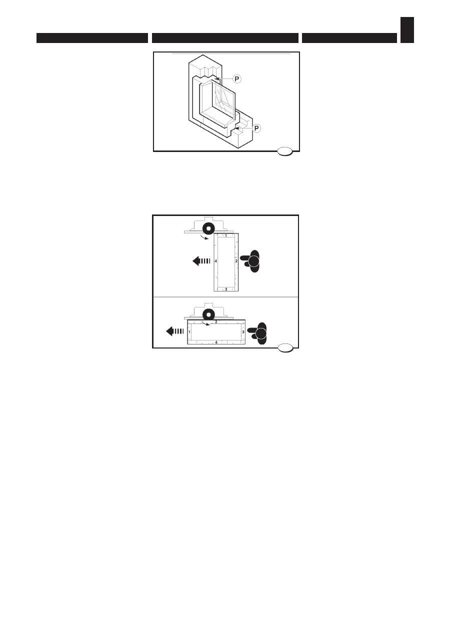
La sbattentatura è la profi latura
esterna
P
di un telaio (fi g. 19).
Questa operazione si può ese-
guire con il pezzo appoggiato sul
piano della macchina e contro la
guida toupie o serrato sul carro
scorrevole.
E’ preferibile partire da un traverso
e ruotare ogni volta il telaio di 90°
per recuperare la scheggiatura
prodotta nella precedente passata
e fi nire quindi sul montante a favore
di vena dove la scheggiatura è
molto minore (fi g.20).
Rabbeting
It is the external profi ling
P
of a
frame (fi g. 19).
This operation may be carried out
with the workpiece on the machine
table and against the moulder fen-
ce or clamped to the sliding table.
It is better to begin from a crosspie-
ce then turn the frame 90° every
time in order to eliminate the
chipping obtained in the previous
stroke, then work the jamb in the
wood grain direction (fi g. 20).

- 125 -
РАБОЧИЕ ПРОЦЕДУРЫ • NORMES POUR LE FONCTIONNEMENT
NORMAS DE FUNCIONAMIENTO
FRANÇAIS
РУССКИЙ
ESPAÑOL
6.
Обгонка
О б го н к а - эт о п р од ол ь н о е
профильное фрезерование P
в н е ш н е й с т о р о н ы р а м н о й
конструкции (рис.19).
Д а н н а я о п е р а ц и я м о ж е т
выполняться с базированием
з а г о т о в к и н а с т о л е п о
направляющей линейке либо
с закреплением заготовки на
каретке.
Р е к о м е н д у е т с я н а ч и н а т ь
обработку с поперечного элемента
рамы и поворачивать раму каждый
раз на 90°. Такой способ позволяет
устранить сколы, появляющиеся на
проходе предыдущего элемента.
При этом завершающий проход
производится по вертикальному
э л е м е н т у в н а п р а в л е н и и
волокон, что приводит лишь к
незначительным сколам (рис.20).
Chantournement
Le chantournement est le profi lage
extérieur
P
d’un chassis (fi g. 19).
Cette opération peut être exécutée
avec la pièce sur la table de la ma-
chine et contre le guide toupie ou
serrée sur le chariot.
On recommande de commencer
par une traverse, de tourner chaque
fois le chassis 90° pour eliminer la
brisure produite pendant la passe
précedente et de fi nir sur le montant
(fi g. 20).
Perfi ladura exterior
Es la perfi ladura exterior
P
de un
bastidor (fi g. 19).
La perfi ladura exterior puede efec-
tuarse con una pieza apoyada sobre
la mesa de la máquina y contra la
guía tupí o bien sobre el carro de-
slizante.
Se aconseja partir de un través y
girar cada vez el bastidor de 90° con
el fi n de recuperar el astillado que se
ha producido en la pasada anterior y
acabar sobre el montante en la vena,
donde el astillado es menor (fi g. 20).
6.
NORME DI FUNZIONAMENTO • OPERATING PROCEDURES
ENGLISH
ITALIANO
– 126 –
63_070_0.tif
22
63_138_0.tif
21
•
C
A
•
•
D
•
E
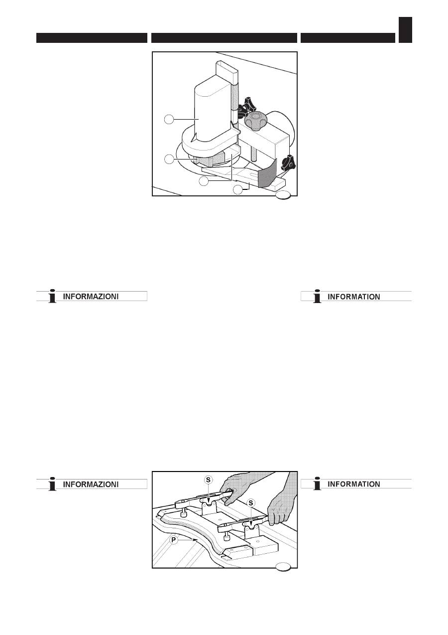
Sagomatura
L’operazione di sagomatura consi-
ste nell’esecuzione di profi li lungo
linee curve.
La sagomatura si effettua me-
diante fresa
A
(fi g. 21) e anello
copiatore
D
montati sulla cuffi a
C
.
Regolare la cuffi a come indicato al
paragrafo 5.6.
Prima di iniziare a lavorare verifi -
care i vari fi ssaggi.
Per la lavorazione procedere ap-
poggiando la sagoma sulla guida
E
(fi g. 21), fi ssata solidamente al
supporto e spingerla fi no al riferi-
mento
D
stampigliato sulla lunetta.
Si ottiene così un attacco progres-
sivo fi no alla massima profondità
di passata.
Il riferimento
D
indica il punto di
massima profondità di passata.
Per avere un'asportazione
regolare è necessario
eseguire tutta la lavorazione in
corrispondenza del riferimento D.
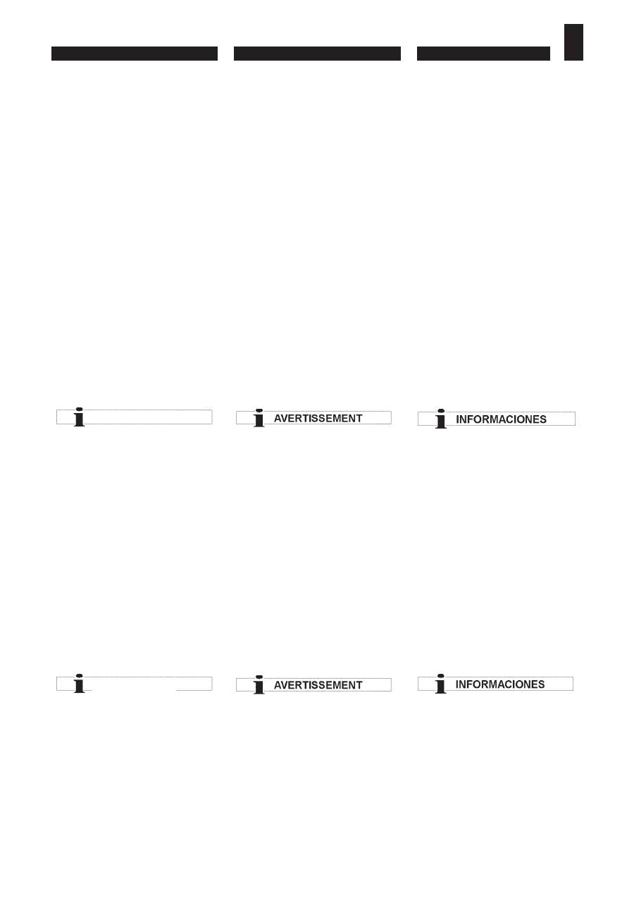
La sagoma (P fi g. 22) deve essere
costruita con materiali il più
possibile indeformabili
(es.: multistrato) e munita di
morsetti stringipezzo S.
Shaping
This operation is carried out for
obtaining profi les along bent lines.
The shaping is carried out by
means of the milling cutter
A
(Fig. 21) and the copying ring
D
fi tted on the hood
C
.
Adjust the hood as indicated in
paragraph 5.6.
Before starting work check the
various fi ttings.
For machining proceed by placing
the profi le on the guide
E
(Fig. 21),
fi rmly fi xed to the support and push
it up to the reference
H
stamped
on the rest.
Thus progressive attachment is
obtained until maximum cutting
depth.
The reference
H
indicates the point
of maximum cutting depth.
To obtain regular removal the
whole machining process must be
carried out in correspondence to
the reference D.
As a material for the template
(P fi g. 22) use a multilayer panel;
the template shall be equipped
with clamps S.
- 127 -
РАБОЧИЕ ПРОЦЕДУРЫ • NORMES POUR LE FONCTIONNEMENT
NORMAS DE FUNCIONAMIENTO
FRANÇAIS
РУССКИЙ
ESPAÑOL
6.
Криволинейное фрезерование
по шаблону
О п е р а ц и я к р и в о л и н е й н о г о
фрезерования по шаблону состоит
в выполнении профилей вдоль
кривых линий.
Криволинейное фрезерование по
шаблону проводится при помощи
фрезы A (рис. 21) и кольцевого
копира D, закрепляемого на
ограждении C.
Настроить ограждение, как указано
в параграфе 5.6.
Перед началом работы проверить
различные элементы крепления.
При работе прижать шаблон к
направляющей линейке E (рис.
21), жестко закрепленной на
опоре, и сдвинуть его до метки D,
выбитой на копире.
Данный способ обеспечивает
плавный выход на максимальную
глубину съема.
Метка D соответствует точке с
максимальной глубиной съема.
Для равномерного снятия
припуска необходимо выполнять
фрезерование в точке,
соответствующей метке D.
Шаблон P (рис. 22) должен
быть изготовлен из
малодеформируемого материала
(например, фанеры) и снабжен
зажимами S.
Façonnage
L’opération de façonnage consiste à
exécuter des profi ls lelong des lignes
courbes.
Le façonnage s’obtient au moyen
de la fraise
A
(fi g. 21) et au moyen
de l’anneau copieur
D
montés sur
le capot
C
.
Régler le carter de protection comme
indiqué au paragraphe 5.6.
Avant de commencer l’usinage
contrôler les différentes fi xations.
Pour l’usinage procéder en appuyant
le profi l sur le rail
E
(fi g. 21), fi xé
solidement au support et le pous-
ser jusqu’au repère
H
gravé sur
l’anneau.
De cette manière on obtient une
attaque progressive jusqu’à la pro-
fondeur maximum de passage.
Le repère
H
indique le point maximum
de profondeur de passage.
Pour avoir un enlèvement régulier, il
faut exécuter tout l’usinage en face
du repère D.
Le gabarit (P fi g.22) doit
être fabriqué avec du matériel le
plusindéformable que possible
(ex. matériel feuilleté) et pourvude
bornes
serre-pièce S.
Perfi lado
El perfi lado es la ejecución de perfi -
les a lo largo de líneas curvas.
El perfi lado se efectúa mediante
fresa
A
(fi g. 21) y anillo copiador
D
montados sobre la envoltura
C
.
Regular la protección como se indica
en el punto 5.6.
Antes de comenzar a trabajar, con-
trolar todas las fi jaciones.
Para proceder a la elaboración, apo-
yar el patrón sobre la guía
E
(fi g. 21)
fi jada fuertemente al soporte y em-
pujarlo hasta la marca de referencia
H
estampada en el anillo.
De ese modo, se obtiene una unión
progresiva hasta la máxima profun-
didad de pasada.
La marca de referencia
H
indica el
punto de máxima profundidad de
pasada.
Para que la remoción sea precisa,
es necesario efectuar toda la elabo-
ración tomando como referencia la
marca D.
El perfi l (P fi g. 22) debe ser
fabricado con materiales lo
menos deformable posible (ej.: de
varias capas) y dotado de morsas
aprietapiezas S.
ИНФОРМАЦИЯ
ИНФОРМАЦИЯ
6.
NORME DI FUNZIONAMENTO • OPERATING PROCEDURES
ENGLISH
ITALIANO
– 128 –
049.079.0.tif
A
23
63_069_0.tif
24
25
63_061_0.tif
Profi latura
La profi latura è una fresatura che
avviene lungovena su pezzi diritti
(fi g. 23).
Durante l’avanzamento il pezzo
deve essere a contatto, per tutta
la sua lunghezza, con i piani della
guida toupie. Prima di procedere
alla lavorazione registrare la cuffi a
toupie e i pressatori come indicato
nel cap.5.
L'avanzamento del pezzo in
lavorazione deve essere eseguito
sempre con lo spingilegno in
dotazione
(A fi g. 23).
Avviare la macchina e passare un
pezzo campione.
Verifi care con un calibro il profi lo
in altezza e in profondità.
Per una buona fi nitura, eseguire
la fresatura con avanzamento
costante.
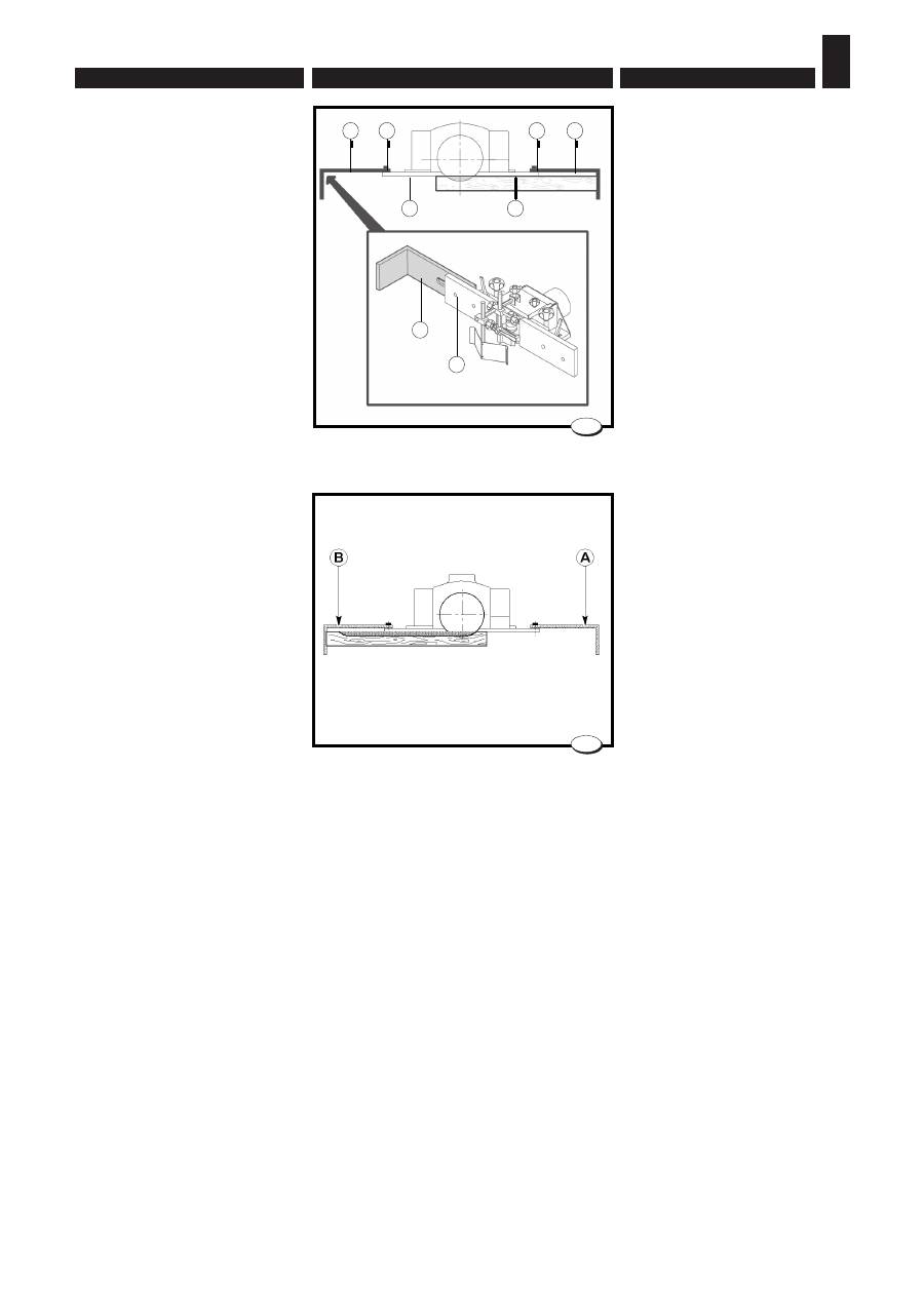
Per fresature non passanti (
H
fi g.
25) e lavorazioni di pezzi corti, è
indispensabile creare sulla guida
in ingresso e su quella in uscita,
delle battute antirigetto
A
e
B
(non
in dotazione).
Profi ling
It is carried out along the wood
grain on straight pieces (fi g. 23)
During the feed motion the entire
workpiece shall be in contact with
both half-fences of the moulder
fence. Before proceeding with
machining, adjust the router hood
and the pressers as indicated in
Chap. 5.
The piece being machined must
always be fed using the wood
thrust provided (A fi g. 23).
Start the system and machine
asample workpiece;
Check the profi le height and depth
using a gauge.
A good fi nishing requires a milling
with constant feed.
For dead milling cuts (
H
fi g. 25) and
the machining of short pieces, it is
necessary to fi t the stops
A
and
B
(not supplied) onto the input fence
and the half–fence.
- 129 -
РАБОЧИЕ ПРОЦЕДУРЫ • NORMES POUR LE FONCTIONNEMENT
NORMAS DE FUNCIONAMIENTO
FRANÇAIS
РУССКИЙ
ESPAÑOL
6.
П р о д ол ь н о е п р о ф и л ь н о е
фрезерование
П р о д о л ь н о е п р о ф и л ь н о е
фрезерование - это фрезерование
прямолинейных заготовок в
направлении волокон (рис.23).
При подаче заготовка должна
прижиматься по всей длине
к н а п р а вл я ю щ и м л и н е й к а м
фрезерного узла. Перед началом
работы следует отрегулировать
ограждение шпинделя и прижимы,
как указано в главе 5.
Для подачи заготовки
использовать прилагаемый
толкатель A (рис. 23).
Включить станок и выполнить
обработку пробной заготовки.
Штангенциркулем проверить
высоту и глубину профиля.
Д л я д о с т и ж е н и я в ы с о к о г о
качества обработки выполнять
фрезерование на постоянной
скорости подачи.
Для несквозного фрезерования
(H рис.25) и обработки коротких
заготовок необходимо укрепить на
передней и задней направляющих
линейках упоры A и B, служащие
для защиты от выброса заготовки
(не прилагаются в комплекте).
Profi lage
Le profi lage est un fraisage long de
la veine du bois sur pièces droites
(fi g. 23).
Pendant l’avance toute la pièce doit
être en contact avec les 2 demi-
guides de la toupie.
Avant d’effectuer l’usinage régler la
protection toupie et les presseurs
comme indiqué au chapitre 5.
L’avancement de la pièce en
usinage doit toujours être effectué
à l’aide du pousse-bois fourni en
équipement (A fi g.23).
Mettre en marche la machine et
passer une pièce échantillon;
Contrôler à l’aide d’une gauge la
hauteur et la profondeur du profi l.
Utiliser toujours le poussoir.
Exécuter le fraisage avec avance
constante.
Pour fraisages non débouchants
(
H
fi g. 25) et usinage de pièces
courtes, il est indispensable de créer
des butées anti–rejet
A
et
B
soit sur
le guide à l’entrée soit sur celui en
sortie (non fournies).
Perfi ladura
La perfi ladura es un fresado que se
efectúa al costado de la vena sobre
las piezas derechas (fi g. 23).
Durante el avance, la pieza debe
estar en contacto, por toda su lon-
gitud, con las mesas de la guía tupí.
Antes de proceder a la elaboración,
calibrar la protección tupí y las pren-
sas como se indica en el cap. 5.
El avance de la pieza en elaboración
debe ser efectuado siempre con el
elemento de presión para madera
que se entrega con la máquina (A
fi g.23).
Poner en marcha la máquina y pasar
una pieza de muestra;
Verifi car con un calibre el perfi l en
altura y en profundidad.
Para un buen acabado, efectuar el
fresado con avance constante.
Para fresados no pasantes (
H
fi g. 25)
y elaboraciones de piezas cortas, es
indispensable preparar, sobre las
guías en entrada y en salida, algunos
topes anti-rechazo
A
y
B
(no sumini-
strados en el equipamiento de base).
ВНИМАНИЕ
6.
NORME DI FUNZIONAMENTO • OPERATING PROCEDURES
ENGLISH
ITALIANO
– 130 –
040_082_0.tif
26
B
C
B
C
C
A
D
D
63_062_0.tif
27
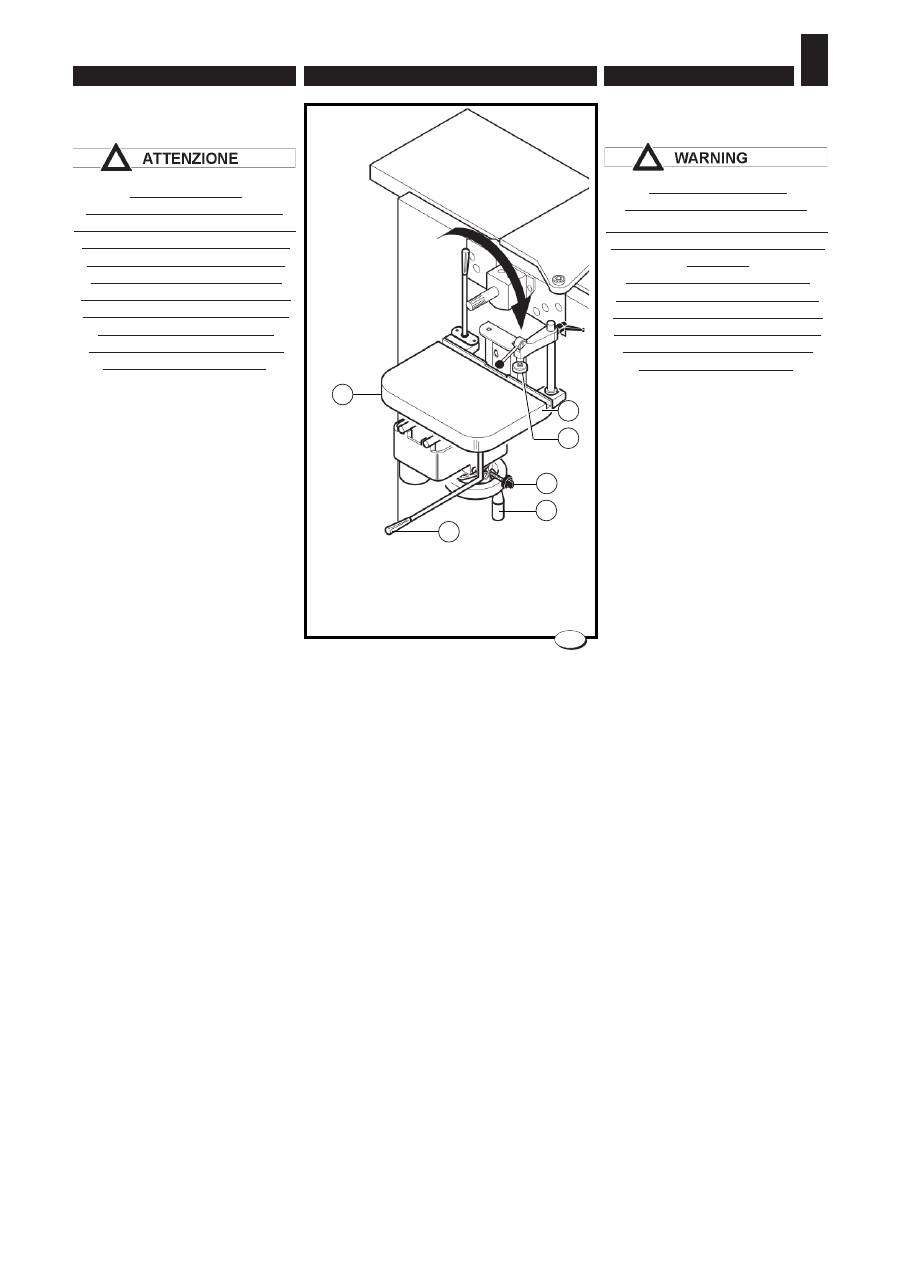
Queste devono essere fi ssate con
le viti
C
sulle guide
D
(fi g. 26).
Per la lavorazione operare nel
seguente modo:
– predisporre la macchina;
– avviare l'albero toupie;
– appoggiare il legno contro la
battuta
A
e spingerlo contro la
fresa (fi g. 26);
– avanzare con il pezzo fi no alla
battuta
B
(fi g. 27).
The stops must be fastened on-
tothe fences
D
by means of the
screws
C
(fi g. 26).
To perform the machining, proceed
as follows:
– prepare the machine;
– start the moulder shaft;
– rest the wood piece against the
stops
A
and push it against the
milling cutter (fi g. 26);
– move the piece forward to the
stop
B
(fi g. 27).

- 131 -
РАБОЧИЕ ПРОЦЕДУРЫ • NORMES POUR LE FONCTIONNEMENT
NORMAS DE FUNCIONAMIENTO
FRANÇAIS
РУССКИЙ
ESPAÑOL
6.
Упоры крепятся винтами C на
направляющих линейках D
(рис.26).
Придерживаться следующего
порядка работы:
– подготовить станок;
– включить шпиндель;
– прижать заготовку к упору A и
подать ее на фрезу (рис. 26);
;
– подавать заготовку до упора B
(рис. 27).
Celles–ci doivent être fi xées par les
vis
C
sur les guides
D
(fi g. 26).
Pour l’usinage, opérer de la façon
suivante:
– préparer la machine;
– démarrer l’arbre toupie;
– appuyer le panneau contre les
butées
A
et le pousser contre la
fraise (fi g. 26);
– avancer la pièce jusqu’à la butée
B
(fi g. 27).
Sujetar los topes con los tornillos
C
sobre las guías
D
(fi g. 26).
Para el trabajo, obrar de la manera
siguiente:
– preparar la máquina;
– poner en funcionamiento el árbol
tupí;
– apoyar la madera contra el tope
A
y apretarla contra la fresa
(fi g. 26);
– avanzar con la pieza hasta el tope
B
(fi g. 27).
6.
NORME DI FUNZIONAMENTO • OPERATING PROCEDURES
ENGLISH
ITALIANO
– 132 –
040_098_0.tif
28
G
F
B
A
H
C
6.6. LAVORAZIONI CON LA
CAVATRICE
ATTENZIONE AL
COLLEGAMENTO ELETTRICO
L'utensile deve obbligatoriamente
ruotare nel senso indicato dalla
freccia di fi g. 28. Accendere la
macchina per una frazione di
secondo verifi cando il senso di
rotazione; nel caso la rotazione
non sia corretta, seguire le
indicazioni riportate nel cap.4
"Collegamento elettrico".
Montare l'utensile seguendo le
istruzioni e attenzioni riportate nel
cap.5.
Verifi care che l'utensile sia ben
serrato.
Fra due utilizzi della cavatrice
smontare la punta, poiché la sua
rotazione è comune all’albero di
piallatura a fi lo e la punta non può
essere protetta.
Verifi care sempre che il pezzo sia
ben serrato sul piano
Per i pezzi lunghi, utilizzare un
supporto regolabile in altezza e
aggiungere, all’occorrenza, un
morsetto sul piano.
Con la cavatrice, o mortasa, si
possono eseguire fori e asole
(bedanature) cieche o passanti.
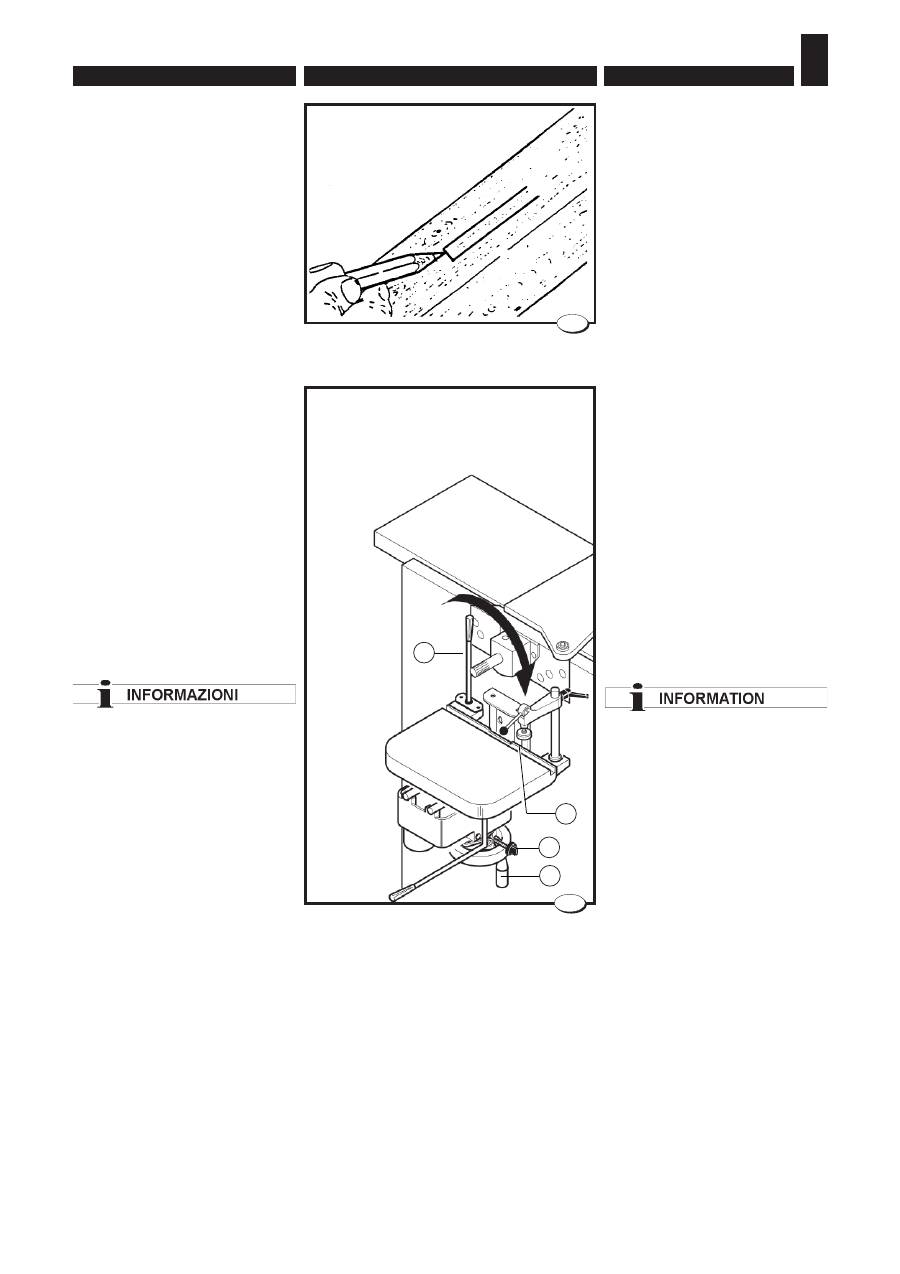
Per fori non passanti occorre
registrare la corsa del pianetto
A
(fi g. 28) in profondità:
– posizionare il pezzo sul piano
A
e fi ssarlo tramite pressore
B
;
– posizionare il piano in altezza
tramite il volantino
C
e bloccare
serrando il pomello
G
;
– provare la corsa in avanti tra-
mite la leva
F
e registrare la
battuta di profondità tramite il
pomello
H
.
6.6. WORKING WITH SLOT-
TER
CAREFUL WITH THE
ELECTRICAL CONNECTION
The tool must turn in the direction
indicated by the arrow as shown
in fi g. 28.
Switch on the machine for a
fraction of a second and check
the direction of rotation. Should
rotation be incorrect, follow the
instructions listed in Chap. 4
“Electrical connection”.
Mount the tool following the
instructions and warnings listed
in Chap. 5.
When the slotter is not in use, it
is necessary to disassemble the
bit, as it rotates jointly with the
surfacing table shaft and it cannot
be protected.
Always check that the piece is
well locked to the table
For long workpieces, use a
support that can be adjusted
as for its height and apply, if
necessary, a clamp to the table.
With the use of slotter it is possible
to carry out holes and slots both
dead or through.
In the case of dead holes you have
to adjust the stroke of additional
table
A
(fi g. 28):
– position the workpiece on the
table
A
, clamp it by presser
B
;
–
position the table in height by
means of the handwheel
C
and
lock by tightening the knob
G
;
– test the forward stroke using
lever
F
and adjust the depth stop
using knob
H
.

- 133 -
РАБОЧИЕ ПРОЦЕДУРЫ • NORMES POUR LE FONCTIONNEMENT
NORMAS DE FUNCIONAMIENTO
FRANÇAIS
РУССКИЙ
ESPAÑOL
6.
6.6. РАБОТА НА
ПАЗОВАЛЬНОМ УЗЛЕ
ПРИ ЭЛЕКТРИЧЕСКОМ
ПОДКЛЮЧЕНИИ БЫТЬ
ВНИМАТЕЛЬНЫМ!
Инструмент обязан вращаться
в направлении, указанном
стрелкой на рис. 28. Для проверки
направления вращения включить
станок на несколько долей
секунды. Если направление
вращения неверное, выполнить
действия, описанные в главе 4
"Подключение к электросети".
Монтировать инструмент с
соблюдением инструкций и
предостережений главы 5.
Убедиться, что инструмент
надежно затянут.
Когда пазовальный узел не
используется, необходимо
демонтировать концевую
фрезу. Данная мера
необходима в связи с тем, что
фреза вращается совместно с
ножевым валом фуговально-
рейсмусового узла, при этом
оставаясь не защищенной.
Убедиться, что заготовка
надежно закреплена на столе.
Для закрепления длинных
заготовок использовать
регулируемую по высоте
опору. При необходимости
установить на стол
дополнительную струбцину.
Пазовальная (или долбежная)
приставка позволяет выполнять
отверстия и пазы - сквозные или
несквозные.
Для выполнения несквозных
отверстий необходимо настроить
ход стола A (рис. 28) по глубине:
– поместить заготовку на стол A и
закрепить ее прижимом B;
– установить стол на требуемую
в ы с о т у м а х о в и ч к о м C и
зафиксировать его барашковым
винтом G;
– проверить ход подачи заготовки
в переднем направлении при
помощи рычага F. Отрегулировать
положение упора по глубине при
помощи барашкового винта H.
6.6.
TRAVAIL AVEC
LA MORTAISEUSE
ATTENTION AU BRANCHEMENT
ELECTRIQUE
L’outil doit obligatoirement tourner
dans le sens indiqué par la fl èche
de la fi g. 28.
Actionner la machine pendant une
fraction de seconde en vérifi ant le
sens de rotation: si la rotation n’est
pas correcte, suivre les indications
fi gurant au chapitre 4 “Branchement
électrique”.
Monter l’outil en suivant les
instructions et les consignes
fi gurant au chap. 5.
Entre deux utilisations de la
mortaiseuse démonter la mèche, car
sa rotation est comune à l'arbre de
dégauchisseuse et la mèche ne peut
être protégée.
Vérifi er toujours que la pièce soit
bien bridée sur la table
Pour les pièces longues utiliser
une servante réglable en hauteur
et ajouter éventuellement un serre
joint sur la table.
Avec la mortaiseuse on peut exé-
cuter des trous et mortaises debou-
chantes ou borgnes.
Pour trous borgnes il faut régler la
course de la table supplémentaire
A
(fi g. 28) en profondeur:
– positionner la pièce sur la table
A
et la serrer par presseur
B
;
– placer le plan en hauteur par l’in-
termédiaire du volant
C
et bloquer
en serrant la poignée
G
;
– essayer la course en avant avec
le levier
F
et régler la butée de
profondeur avec le bouton
H
.
6.6. TRABAJOS CON LA RA-
NURADORA
CUIDADO CON LA CONEXIÓN
ELÉCTRICA
La herramienta tiene que girar
obligatoriamente en sentido
indicado por la fl echa de la fi gura
28.
Encienda la máquina por una
fracción de segundo comprobando
el sentido de rotación: si la rotación
no es correcta, siga las indicaciones
que encontrará en el capítulo 4
“Conexión eléctrica”.
Montar la herramienta siguiendo
las instrucciones y advertencias
indicadas en el cap. 5.
Entre dos ciclos de trabajo con la
mortajadora hace falta desmontar la
punta, ya que su rotación es común
para el árbol de acepilladura de eje
vertical y la punta no puede ser
protegida.
Controlar siempre que la pieza
estén bien apretada sobre el plano
Para las piezas largas, usar un
soporte regulable y añadir, cuando
necesario, una morsa sobre el
plano.
Mediante la ranuradora o mortaja,
es posible efectuar agujeros o ojales
ciegos o pasantes.
Para los agujeros no pasantes hace
falta regular la carrera del plano
A
(fi g. 28) en profundidad:
– colocar la pieza sobre la mesa
A
y fi jarla mediante prensador
B
;
– regular la altura de la mesa me-
diante el volante
C
y bloquear
apretando el pomo
G
;
– intentar la carrera hacia delante
por medio de la palanca
F
y regular
el tope de profundidad por medio
de la perilla
H
.
ВНИМАНИЕ
6.
NORME DI FUNZIONAMENTO • OPERATING PROCEDURES
ENGLISH
ITALIANO
– 134 –
29
011.048 Ed.0
040_107_1.tif
30
G
B
C
D
Per bedanature non passanti
occorre registrare la corsa in pro-
fondità, come già visto:
– segnare a matita sul pezzo la
zona della cava da eseguire
(fi g. 29);
– posizionare il pezzo sul piano e
fi ssarlo con pressore
B
;
– posizionare il piano in altezza
tramite il volantino
C
e bloccare
serrando il pomello
G
;
– provare la corsa orizzontale
tramite leva
D
in funzione della
cava da eseguire e registrare di
conseguenza la battuta laterale
tramite il pomello sotto il piano.
Per le bedanature
occorre eseguire una serie di fori
vicini, poi facendo traslare il piano
tramite la leva (D), si
pulisce completamente
l’interno della cava.
In the case of dead slots adjust
the stroke depth as already seen:
– mark on the workpiece the
area where you want to carry
out the slot (fi g. 29);
– set the workpiece on the table
and clamp it with presser
B
;
– position the table in height by
means of the handwheel
C
and
lock by tightening the knob
G
;
– check horizontal stroke with lever
D
, adjust the stop by the knob
under the table.
To carry out slots, it is necessary
to drill a row of holes, then,
moving the table by means of the
lever (D), the inside of the slot is
thoroughly cleaned.
- 135 -
РАБОЧИЕ ПРОЦЕДУРЫ • NORMES POUR LE FONCTIONNEMENT
NORMAS DE FUNCIONAMIENTO
FRANÇAIS
РУССКИЙ
ESPAÑOL
6.
Для выполнения несквозных пазов
необходимо отрегулировать ход
по глубине, как описано выше, а
также горизонтальный ход стола:
– п о м ет и т ь к а р а н д а ш о м н а
заготовке участок выбираемого
паза (рис. 29);
– поместить заготовку на стол и
закрепить ее прижимом B;
– установить стол на требуемую
в ы с о т у м а х о в и ч к о м C и
зафиксировать его барашковым
винтом G;
– п р о в е р и т ь х о д п о д а ч и
заготовки в горизонтальном
н а п р а вл е н и и п р и п о м о щ и
рычага D. Отрегулировать
положение бокового упора при
помощи барашкового винта,
расположенного под столом.
Для выполнения паза
необходимо выполнить ряд
расположенных близко друг
к другу отверстий, а затем,
“вычистить” паз, перемещая стол
в горизонтальном направлении
при помощи рычага D.
Pour mortaises debouchantes il faut
régler la profondeur de la course:
– avec crayon marquer sur la pièce
la zone ou on exécute la mortaise
(fi g. 29);
– serrer la pièce sur la table par
presseur
B
;
– Placer le plan en hauteur par l’in-
termédiaire du volant
C
et bloquer
en serrant la poignée
G
;
– vérifi er la course horizontale par
levier
D
en fonction de la mortaise,
régler la butée par la poignée sous
la table.
Pour les mortaises il faut exécuter
une série de trous , puis, en
déplaçant la table à l’aide du levier
(D), on nettoie complètement la
mortaise au dedans.
Para ojales no pasantes hace falta
ajustar la carrera en profundidad,
como ya explicado, y la carrera ho-
rizontal del plano:
– marcar con un lápiz la zona la ranura
a efectuar sobre la pieza (fi g. 29);
– colocar la pieza sobre la mesa y
fi jarla mediante prensador
B
;
– regular la altura de la mesa me-
diante el volante
C
y bloquear
apretando el pomo
G
;
– intentar la carrera horizontal me-
diante palanca
D
según la ranura a
efectuar y regular en consecuencia
el tope lateral mediante el pomo
bajo la mesa.
Para los ojales hace falta efectuar
una serie de agujeros cercanos,
y luego limpiar completamente la
parte interior de la ranura dejando
traslar el plano mediante la palanca
(D).
ИНФОРМАЦИЯ

7.
ESIGENZE DI MANUTENZIONE • MAINTENANCE REQUIREMENTS
ENGLISH
ITALIANO
– 136 –
É obbligatorio prima di ogni
intervento di manutenzione
mettere a O l'interruttore generale
e scollegare la spina dalla presa.
7.1. CINGHIE TRAPEZOIDALI
- SOSTITUZIONE E TEN-
SIONAMENTO
Verifi care il grado di tensionamento
dopo le prime 10 ore di funziona-
mento della macchina.
Dei controlli periodici dovranno es-
sere effettuati sulla cinghia almeno
ogni 6 mesi.
Non eccedere nel tensionamento
delle cinghie per non sovraccari-
care i cuscinetti.
L’eccessivo tensionamento, pro-
voca lo stiramento delle cinghie,
surriscaldamento e la rapida di-
struzione delle stesse.
Verificare almeno una volta al
mese il tempo di arresto dell'albero
pialla,della lama sega e dell'albe-
ro toupie con utensile e velocita'
massima ammessa; se il tempo di
arresto supera i 10 secondi inter-
venire tensionando o sostituendo
le cinghie (nel caso siano rovinate)
come indicato nei paragrafi che
seguono.
A regolazione eseguita verifi care
nuovamente il tempo di arresto.
Before starting any servicing,
the main switch must be set to O
and the plug disconnected from
socket.
7.1. V-BELT REPLACEMENT
AND TIGHTENING
Check the belt tension after the
fi rst 10 hours of machine operation.
At least every 6 months,it is neces-
sary to perform a periodical check
on the belt.
Do not overstretch the belts not to
overload the bearings.
Overstretching may overheat and
destroy the belts.
At least once a month check
the stopping times of the planer
spindle, the saw blade and the ro-
uter spindle with tool and maximum
permitted speed; if the stopping
time exceeds 10 seconds, act by
tightening or replacing the belts
(should they be worn) as described
in the following paragraphs.
After the adjustments have been
made, again check the stopping
time.
– 137 –
7.
ПРОЦЕДУРЫ ТЕХНИЧЕСКОГО ОБСЛУЖИВАНИЯ • NORMES POUR L'ENTRETIEN
EXIGENCIAS PARA EL MANTENIMIENTO
FRANÇAIS
РУССКИЙ
ESPAÑOL
Перед началом любых действий
по техническому обслуживанию
станка необходимо перевести
в положение O выключатель
питания и отсоединить вилку от
розетки.
7.1. КЛИНОВИДНЫЕ РЕМНИ –
ЗАМЕНА И ПОДТЯЖКА
Проверить натяжение приводных
ремней после первых 10 часов
работы станка.
Состояние приводного ремня
следует проверять не реже одного
раза в 6 месяцев.
Не перетягивать ремни, чтобы не
создавать чрезмерной нагрузки на
подшипники.
Избыточное натяжение приводит к
растяжению ремней, их перегреву
и быстрому износу.
Не реже раза в месяц необходимо
проверять время остановки
ножевого вала, пилы и фрезерного
шпинделя (при установленных
инструментах и максимально
допустимой скорости вращения).
Если время остановки превышает
10 секунд, надлежит подтянуть
и л и з а м е н и т ь р е м н и ( е с л и
они изношены), как описано в
следующих параграфах.
После завершения процедуры
выполнить повторную проверку
времени остановки.
Il est obligatoire, avant de
tout réglage, de mettre sur O
l’interrupteur général et de
débrancher la fi che de la prise.
7.1. COURROIES TRAPE-
ZOIDA-LES - REMPLA-
CEMENT ET MISE SOUS
TENSION (fi g. 1)
Contrôler la tension des courroies
après les dix premières heures de
fonctionnement de la machine.
Il faut vérifi er la performance de la
courroie au moins tous les 6 mois.
La tension des courroies ne devra
pas être excessive pour ne pas sur-
charger les paliers.
Une tension excessive entraîne
l’étirement des courroies, elles se
surchauffentet elles se détériorent
rapidement.
Contrôler, au moins une fois par
mois, le temps d’arrêt de l’arbre ra-
bot, de la lame scie et de l’arbre tou-
pie avec l’outil et la vitesse maximale
admise; si le temps d’arrêt dépasse
10 secondes intervenir en tendant ou
en remplaçant les courroies (si elles
sont abîmées) comme indiqué dans
les paragraphes suivants.
Après le réglage contrôler de nou-
veau le temps d’arrêt.
Antes de efectuar cualquier
regulación, es obligatorio poner
el interruptor general en pos. O y
desconectar el enchufe de la toma.
7.1. CORREAS TRAPEZOI-
DALES - SUSTITUCION Y
TENSION (fi g. 1)
Verifi car el grado de tensión después
de las primeras 10 horas de funcio-
namiento de la máquina.
Cada 6 meses es necesario controlar
periódicamente la correa.
No excederse en la tensión de las
cintas para no sobrecargar los co-
jinetes.
La excesiva tensión provoca el esti-
ramiento de las correas, el recalen-
tamiento y la rápida destrucción de
las mismas.
Comprobar por lo menos una vez al
mes el tiempo de parada del árbol
cepillo, de la cuchilla de la sierra y del
árbol tupí con herramienta a la veloci-
dad máxima permitida; si el tiempo de
parada supera los 10 segundos hay
que intervenir tensando o cambiando
las correas (si estuvieran rotas) como
indican los puntos siguientes.
Una vez efectuada la regulación
comprobar de nuevo el tiempo de
parada.
ВНИМАНИЕ
7.
ESIGENZE DI MANUTENZIONE • MAINTENANCE REQUIREMENTS
ENGLISH
ITALIANO
– 138 –
040_065_0.tif
2
A
3
040_066_1.tif
A
040_064_0.tif
A
C
1
A
B
A
A
C
B
E
D
E
F
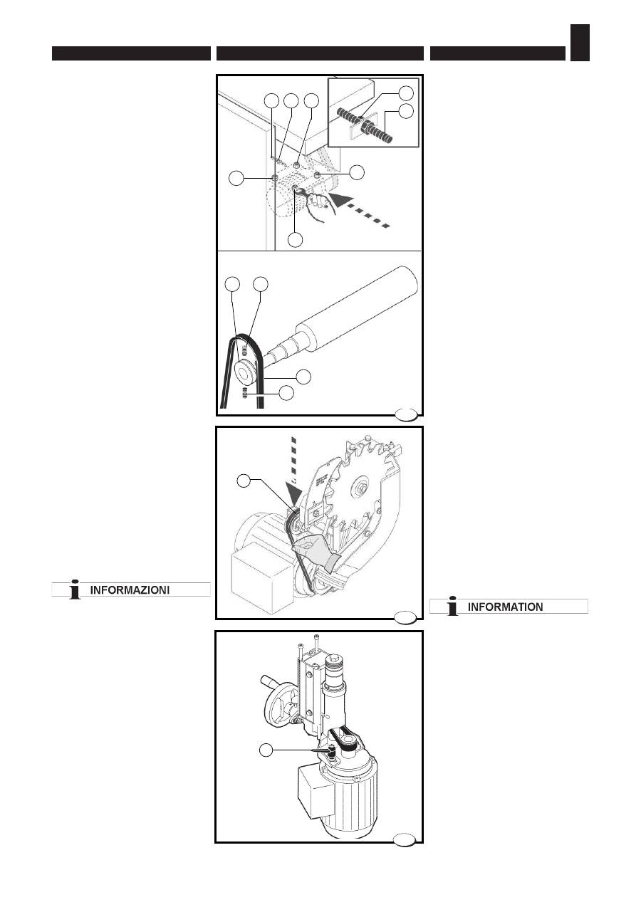
7.1.1 Cinghia di comando al-
bero pialla (fi g.1)
Aprire lo sportello toupie e pro-
cedere come descritto di seguito:
- Alzare il piano spessore agendo
sul volantino.
- Allentare i 4 dadi
A
di fi ssaggio
del supporto motore.
- Allentare il dado
C.
- Allentare la vite
B
di registrazio-
ne per detensionare la cinghia.
- Sfi lare la puleggia
D
dall'albero
pialla dopo aver tolto i due grani
E
.
- Rimuovere la cinghia.
- Inserire la nuova cinghia
F
nella
gola della puleggia
D
.
- Inserire la puleggia
D
dell'albero
e fi ssarla serrando i due grani
E
.
Accertarsi che i grani siano avvi-
tati correttamente nelle rispettive
sedi.
- Tensionare la cinghia avvitando
la vite
B
.
A regolazione eseguita stringere
i dadi
A
e il dado
C
.
7.1.2 Cinghie trasmissione
sega (fi g.2)
– Aprire lo sportello.
– Abbassare completamente la
lama sega.
– Spingere il tenditore
A
verso il
basso e sfi lare la cinghia.
– Inserire la nuova cinghia.
Il giusto tensionamento della
cinghia è assicurato dal gruppo
tendicinghia A e non necessita di
alcuna regolazione.
7.1.3 Cinghia di comando al-
bero toupie (fi g.3)
Aprire lo sportello toupie e pro-
cedere come descritto di seguito:
Allentare la maniglia
A
e agire sul
motore per tensionare la cinghia.
Stringere la maniglia a regolazione
eseguita.
Per sostituire la cinghia fare riferi-
mento alle istruzioni riportate nel
par. 5.7.
7.1.1 Cutterblock driving belt
(fi g.1)
Open the router door and proceed
as described below:
– Raise the thicknesser table using
the handwheel.
– Loosen the 4 retaining nuts
A
of
the motor support.
Slacken nut
C
– Slacken adjustment screw
B
to
slacken belt tension.
– Pull pulley
D
out of the cutter
block after removing the two grub
screws
E
– Remove the belt
– Insert the new belt
F
into groove
of pulley
D
– Insert pulley
D
into the cutter
block and fi x it by tightening the
two grub screws
E.
Ensure that
the grub screws are screwed
tightly into their respective hou-
sings.
– Tighten the belt screwing down
the screw
B
.
When the adjustment has been
made, tighten nuts
A
and
C
.
7.1.2 Saw driving belts (fi g. 2)
– Open the door.
– Lower the saw blade as far as it
will go.
– Push the tensioning rod
A
down
and extract the belt.
– Fit a new belt.
Correct belt tension is guaranteed
by the belt tensioning unit A and
there is no need for adjustments.
7.1.3 Moulder shaft driving
belt (fi g.3)
Open the router door and proceed
as described below:
Unloose handle
A
and act on the
motor to stretch the belt. Tighten
the handle at completion of the
adjustment.
To replace the belt refer to the
instructions in Par. 5.7.
– 139 –
7.
ПРОЦЕДУРЫ ТЕХНИЧЕСКОГО ОБСЛУЖИВАНИЯ • NORMES POUR L'ENTRETIEN
EXIGENCIAS PARA EL MANTENIMIENTO
FRANÇAIS
РУССКИЙ
ESPAÑOL
7.1.1 Ремень привода
ножевого вала (рис.1)
Открыть дверцу фрезерного узла
и выполнить следующие действия:
- Поднять рейсмусовый стол
маховичком.
- Ослабить четыре гайки A
крепления опоры двигателя;
- Ослабить гайку C.
- Открутить регулировочный винт
B, чтобы ослабить натяжение
ремня.
- Снять шкив D с ножевого вала,
предварительно выкрутив пару
винтов E.
- Снять приводной ремень.
- Установить новый ремень F в
канавку шкива D.
- Надеть шкив D на вал и закрепить
его двумя винтами E. Убедиться,
что винты правильно вошли в свои
гнезда.
- Натянуть ремень, закрутив винт
B.
После завершения регулировки
затянуть гайки A и C.
7.1.2 Ремень привода пилы
(рис.2)
– Открыть дверцу.
– Опустить пильный узел в
крайнее нижнее положение.
– Надавить вниз на натяжитель A
и снять ремень.
– Надеть новый ремень.
Правильное натяжение ремня
обеспечивается за счет
натяжителя A. Механизм не
требует регулировки.
7.1.3 Ремень привода
фрезерного шпинделя
(рис.3)
Открыть дверцу фрезерного узла
и выполнить следующие действия:
О с л а б и т ь ф и к с а т о р A и
о т р е г у л и р о в а т ь н а т я ж е н и е
ремня, сдвигая двигатель. После
завершения регулировки затянуть
фиксатор.
Для замены ремня следовать
инструкциям, приведенным в
параграфе 5.7.
7.1.1 Courroie de commande de
l’arbre porte-fers (fi g.1)
Ouvrir la porte toupie et procéder
comme indiqué ci-après:
– Faire monter la table de la rabo-
teuse avec le volant.
– Desserrer les 4 écrous
A
de fi xa-
tion du support moteur.
Desserrer l'écrou
C
.
– Desserrer la vis
B
de réglage pour
détendre la courroie.
– Dégager la poulie D de l’arbre
rabot après avoir enlevé les deux
grains E
– Enlever la courroie
– Introduire la nouvelle courroie
F
dans la gorge de la poulie
D
– Introduire la poulie
D
dans l’arbre
et la fi xer en serrant les deux
grains
E
. S’assurer que les grains
soient bien vissés dans leurs
sièges.
– Tendre la courroie en vissant la vis
B
.
Le réglage terminé, serrer les écrous
A
et l'écrou
C
.
7.1.2 Courroies de transmission
scie
(fi g. 2)
– Ouvrir le portillon.
– Faire descendre complètement la
lame scie.
– Pousser le tendeur
A
vers le bas
et extraire la courroie.
– Installer la nouvelle courroie.
Le tendeur de courroie A fait en
sorte que la courroie soit toujours
correctement tendue ; elle ne
requiert donc aucun réglage.
7.1.3 Courroie de commande de
l’arbre de la toupie (fi g.3)
Ouvrir la porte toupie et procéder
comme indiqué ci-après:
Desserrer la poignée
A
et agir sur le
du moteur pour tendre la courroie.
Serrer la poignée une fois que le
réglage a été effectué.
Pour remplacer la courroie voir les
instructions fi gurant au paragraphe
7.1.1 Correa de comando árbol
cepillo (fi g.1)
Abrir la puerta tupí y proceder como
se describe a continuación:
– Levantar la mesa espesor intervi-
niendo en el volante.
– Afl ojar las 4 tuercas
A
de fi jación
del soporte motor;
– Afl ojar la tuerca
C
– Afl ojar el tornillo
B
de regulación
para afl ojar la correa.
– Extraer la polea D del eje acepilla-
dor después de haber quitado los
dos tornillos sin cabeza
E
– Quitar la correa
– Poner la nueva correa
F
en la
garganta de la polea
D
.
– Encastrar la polea
D
en el eje y
fi jarla apretando los dos tornillos
sin cabeza
E
. Asegurarse que los
tornillos sin cabeza estén enrosca-
dos correctamente en las sedes
respectivas
- Tensar la correa enroscando el
tornillo
B
.
Al fi nalizar la regulación hay que
ajustar las tuercas
A
y la tuerca
C
7.1.2 Correas de transmisión
sierra (fi g. 2)
– Abrir la puerta.
– Bajar por completo la hoja de la
sierra.
– Empujar el tensor
A
hacia abajo y
sacar la correa.
– Insertar la nueva correa.
El tensado adecuado de la correa
está asegurado por el grupo tensor
de correa A y no precisa ningún
ajuste.
7.1.3 Correa de comando árbol
tupí (fi g.3)
Abrir la puerta tupí y proceder como
se describe a continuación:
Afl ojar la manija
A
y regular el mo-
tor para tensar la correa. Apretar
la manija después de efectuar la
regulación.
Para sustituir la correa tomar como
referencia las instrucciones del parr.
5.7.
ИНФОРМАЦИЯ
7.
ESIGENZE DI MANUTENZIONE • MAINTENANCE REQUIREMENTS
ENGLISH
ITALIANO
– 140 –
040_067_1.tif
4
B
A
7.2. CHECKING THE SAFETY
DEVICES
The safety of the machine is a
direct consequence of the state
of effi ciency of the safety devices
used.
Every 2 weeks check the following
devices:
- Check that the safety mi-
croswitches described in Chap.
2 function properly
(U.S.A. and
CANADA version).
- Check that the motors stop when
you press an emergency stop
button (see chapter 6).
- Check the good state of the saw,
router and planer guards (see
Chap. 6), checking that they
function properly and that they
assure effi cient protection.
7.3. OVERALL CLEANING
After each working cycle, thorou-
ghly clean the machine and all of
its parts, vacuum the shavings
and dust and remove any resin
residues.
In particular, clean the following
parts (Fig. 4):
1)
the wagon sliding rail
A
;
2)
the wagon grooves
B
;
Use compressed air when ne-
cessary, using low pressure
guns and wearing protective
glasses and a mask.
Clean the whole inside of the
machine and all the various parts
regularly and whenever necessary.
7.4. GENERAL LUBRICATION
Weekly clean and lubricate all the
mobile couplings of the machine
with a thin fi lm of oil and grease.
Do not lubricate the carriage.
Protect all belts and pulleys to
avoid contamination with oil.
7.2. VERIFICA DISPOSITIVI
DI SICUREZZA
La sicurezza della macchina è
conseguenza diretta dello stato di
effi cienza dei dispositivi di sicurez-
za utilizzati.
Controllare ogni 2 settimane i di-
spositivi seguenti :
- verifi care che i micro di sicurezza
descritti nel cap. 2 funzionino
correttamente
(USA und CA-
NADA -Version).
- verifi care che premendo il pul-
sante di emergenza (vedi cap.6)
i motori si arrestino.
- accertarsi del buono stato delle
protezioni sega,toupie e pialla
(vedi cap.6) verificando che
funzionino correttamente e che
assicurino una protezione effi ca-
ce.
7.3. PULIZIA GENERALE
Dopo ogni ciclo di lavoro, pulire
accuratamente la macchina e tutti
i suoi organi, aspirando trucioli e
polvere, e rimuovere eventuali
residui di resina.
In particolare pulire le seguenti
parti (fi g.4):
1)
la rotaia
A
di scorrimento del
vagone;
2)
le scanalature
B
del vagone.
Usare l'aria compressa solo
quando è strettamente neces-
sario, facendo uso di pistole a
bassa pressione e di indossare
occhiali di protezione e ma-
scherina.
Periodicamente, quando neces-
sario, completare la totale pulizia
all'interno della macchina e di tutti
i suoi organi.
7.4. LUBRIFICAZIONE
GENERALE
Pulire settimanamente e lubrifi care
con un leggero velo di olio e grasso
tutti gli accoppiamenti mobili della
macchina.
Non lubrifi care il carro vagone.
Proteggere tutte le cinghie e le
puleggie per evitarne la possibile
contaminazione con il lubrifi cante.

– 141 –
7.
ПРОЦЕДУРЫ ТЕХНИЧЕСКОГО ОБСЛУЖИВАНИЯ • NORMES POUR L'ENTRETIEN
EXIGENCIAS PARA EL MANTENIMIENTO
FRANÇAIS
РУССКИЙ
ESPAÑOL
7.2. ПРОВЕРКА УСТРОЙСТВ
БЕЗОПАСНОСТИ
Безопасность станка является
прямым следствием исправности
имеющихся в нем устройств
безопасности.
Раз в две недели надлежит
выполнять следующие проверки
устройств безопасности:
- п р о в е р и т ь п р а в и л ь н о с т ь
работы концевых выключателей
безопасности, описанных в главе
2 (исполнение по нормам США и
Канады).
- убедиться, что при нажатии
а в а р и й н о й к н о п к и ( с м .
главу 6) двигатели станка
останавливаются.
- убедиться в исправности
защитных ограждений пилы,
фрезерного шпинделя и ножевого
вала (см. главу 6).
7.3. УБОРКА СТАНКА
После каждого рабочего цикла
надлежит проводить тщательную
уборку станка от пыли, стружки
и смолы.
Использовать сжатый
во з д у х т ол ь к о , к о г д а э т о
строго необходимо, пользуясь
пистолетами низкого давления,
а также носить защитные очки
и маску.
В частности, необходимо очищать
следующие элементы (рис. 4):
1)
н а п р а в л я ю щ а я
A
линейного перемещения каретки;
2)
пазы B на каретке.
По мере необходимости надлежит
п р о в о д и т ь о б щ у ю у б о р к у
внутренних механизмов станка.
7.4. СМАЗКА СТАНКА
Е ж е н е д е л ь н о о ч и щ а т ь и
смазывать тонким слоем масла
или консистентной смазки все
движущиеся механизмы станка.
Не смазывать каретку.
Защитить все приводные ремни
и шкивы от загрязнения смазкой.
5.7.
7.2. VERIFICATION DES DI-
SPOSITIFS DE SECURITE
La sécurité de la machine dépend
directement du bon fonctionnement
des dispositifs de sécurité utilisés.
Contrôler toutes les 2 semaines les
dispositifs suivants:
- vérifi er que les microcontacts de
sécurité décrits au chap. 2 fon-
ctionnent correctement;
(version
U.S.A. et CANADA).
- Vérifi er si en pressant le bouton
d'arrêt d'urgence (voir rubr. 6), les
moteurs s'arrêtent.
- s’assurer du bon état des protec-
tions de la scie, de la toupie et du
rabot (voir chap. 6) en contrôlant
qu’elles fonctionnent correctement
et assurent une protection effi ca-
ce.
7.3. NETTOYAGE GENERAL
Après chaque cycle d’usinage, net-
toyer minutieusement la machine et
tous ses organes, en aspirant les co-
peaux, la poussière et en éliminant
les éventuels résidus de résine.
N’utiliser de l’air comprimé que lor-
sque c’est strictement nécessaire et
en portant des lunettes de protection
et un masque.
En particulier, nettoyer les parties
suivantes (fi g.4):
1)
le rail
A
de coulissement du cha-
riot;
2)
les cannelures
B
du chariot;
Périodiquement, quand c'est néces-
saire, effectuer le nettoyage en
profondeur de la partie interne de
la machine et de tous ses organes.
7.4.
GRAISSAGE GENERAL
Nettoyer chaque semaine et lubri-
fi er avec un léger fi lm d’huile et de
graisse tous les accouplements
mobiles de la machine.
Ne pas lubrifi er le chariot-wagon.
Protéger toutes les courroies et les
poulies pour ne pas les salir avec
le lubrifi ant.
7.2. COMPROBACION DISPO-
SITIVOS DE SEGURIDAD
La seguridad de la máquina es una
consecuencia directa del estado
de efi cacia de los dispositivos de
seguridad utilizados.
Controlar cada dos semanas los
siguientes dispositivos:
- comprobar que los microinterrup-
tores de seguridad descritos en el
cap. 2 funcionen correctamente
(versión U.S.A. y CANADA).
- Asegurarse que al presionar el
botón de emergencia (véase el
cap.6) los motores se paren.
- asegurarse del buen estado de las
protecciones de la sierra, tupí y
cepillo (véase cap. 6) comproban-
do que funcionen correctamente
y que aseguren una protección
efi caz.
7.3. LIMPIEZA GENERAL
Tras cada ciclo de trabajo, limpiar
bien la máquina y todas sus partes,
aspirando las virutas y el polvo y
eliminando también los eventuales
residuos de resina.
Use el aire comprimido sólo cuando
sea estrictamente necesario, hacien-
do uso de pistolas de baja presión
y póngase gafas de protección y
máscara.
En especial, limpiar las siguientes
partes (fi g. 4):
1)
El carril
A
de deslizamiento del
vagón.
2)
Las ranuras
B
del vagón.
Al menos una vez cada 6 meses, o
cada 500 horas, quitar los cárteres
laterales para completar la limpieza
total de la máquina y de todos sus
órganos.
7.4. LUBRICACION GENERAL
Limpiar semanalmente todos los
acoplamientos móviles de la máqui-
na y lubricarlos con una fi na película
de aceite y grasa.
No lubrifi car el carro vagón.
Proteger todas las correas y las
poleas para evitar una posible con-
taminación con el lubricante.

7.
ESIGENZE DI MANUTENZIONE • MAINTENANCE REQUIREMENTS
ENGLISH
ITALIANO
– 142 –
7.5. SOSTITUZIONE E SMAL-
TIMENTO
Qualora fosse necessario, le parti della
macchina devono essere sostituite con
componenti originali di fabbricazione al
fi ne di garantire la loro effi cacia.
Sul catalogo parti di ricambio
con la lettera "C" sono stati
contrassegnati i codici dei ricambi
che incidono sulla sicurezza e sulla
salute degli operatori.
Questi ricambi possono essere in-
stallati anche da personale esperto
incaricato dall'utilizzatore.
Per tutti gli altri ricambi, rivolgersi
al SERVICE del Concessionario/
Rivenditore del Fabbricante oppure
contattare direttamente il SERVICE
del Fabbricante.
Per la rimozione della macchina scolle-
garla dall'impianto elettrico e da quello
pneumatico ed attenersi alle istruzioni
dei paragrafi per il sollevamento.
In caso di una prolungata inattività del-
la macchina, scollegarla dall'impianto
elettrico, eseguire una pulizia accurata
nel modo come già detto per la pulizia
ordinaria e coprire i piani di lavoro, di
scorrimento e alberi portautensili con
protettivo antiruggine.
Non immagazzinare la macchina in
ambienti umidi e proteggerla dagli
agenti atmosferici.
La macchina è costruita con materiali
non tossici nè nocivi; in caso di demo-
lizione separare i materiali ferrosi da
quelli plastici ed avviarli alla rispettiva
rottamazione.
E' obbligatorio che gli operatori
addetti alla moviemntazione ed
i manutentori utilizzino i DPI
previsti in base ai rischi relativi
al tipo d'impiego e conformi alle
leggi e normative vigenti.
7.5. REPLACEMENT AND DI-
SPOSAL
Should replacement become ne-
cessary, the machine parts must
be replaced with original compo-
nents in order to guarantee their
effi ciency.
In the spare parts catalogue the
letter "C" indicates the codes of
spare parts which affect operator
health and safety.
These spare parts can be installed
by expert personnel instructed by
the user.
For all other spare parts contact the
Manufacturer's Dealer SERVICE
or contact the Manufacturer's
SERVICE directly.
To remove the machine, disconnect
it from the electric and pneumatic
system. Follow the instructions in
chap. 4.
In case of extended inactivity of
the machine, disconnect it from the
electrical and pneumatic system.
Thoroughly clean it as already de-
scribed for ordinary cleaning and
cover the work and sliding tables
and the tool holder spindles with
antirust protection. Do not store the
machine in humid environments
and protect it from atmospheric
agents.
The machine is constructed in non-
toxic unharmful materials. In case
of demolition, separate the ferrous
material from the plastic materials
and send them to the respective
scrap yards.
The operators moving the machine
and the maintenance personnel must
wear the IPE required for the risks
involved with the type of use and in
compliance with the applicable laws
and standards.
– 143 –
7.
ПРОЦЕДУРЫ ТЕХНИЧЕСКОГО ОБСЛУЖИВАНИЯ • NORMES POUR L'ENTRETIEN
EXIGENCIAS PARA EL MANTENIMIENTO
FRANÇAIS
РУССКИЙ
ESPAÑOL
7.5. ЗАМЕНА ДЕТАЛЕЙ,
СНЯТИЕ С
ЭКСПЛУАТАЦИИ
Для замены деталей станка должны
использоваться оригинальные
запчасти изготовителя.
ВНИМАНИЕ
В каталоге запчастей буквой "C"
помечены коды тех деталей,
которые непосредственно влияют
на безопасность и здоровье
операторов.
Д а н н ы е
д е т а л и
м о г у т
у с т а н а в л и в а т ь с я , в т о м
числе опытным персоналом,
п р и вл е к а е м ы м вл а д ел ь це м
станка.
Д л я з а м е н ы о с т а л ь н ы х
деталей следует обращаться
в
С Е Р В И С
д и л е р а /
дистрибьютора Изготовителя
либо непосредственно в СЕРВИС
Изготовителя.
Для демонтажа станка отсоединить
его от электро- и пневмосети и
далее следовать инструкциям
п а р а г р а ф а , п о с в я щ е н н о г о
подъему станка.
Если планируется длительный
простой станка, отсоединить
его от электросети, выполнить
тщательную уборку, как указано
в соответствующем параграфе,
и покрыть поверхности столов,
п о в е р х н о с т и с к ол ь ж е н и я и
инструментальные валы средством
для защиты от ржавчины.
Не хранить станок в местах
с высокой влажностью. При
хранении защитить станок от
в о з д е й с т в и я а т м о с ф е р н ы х
осадков.
Станок изготовлен из нетоксичных
б е з в р е д н ы х м а т е р и а л о в .
Д л я у т и л и з а ц и и о т д е л и т ь
м е т а л л и ч е с к и е д е т а л и о т
пластмассовых и направить их
соответствующие пункты приема
отходов.
ВНИМАНИЕ
Работники, участвующие в
перемещении и техническом
обслуживании станка,
обязаны использовать СИЗ,
предусмотренные действующими
нормами безопасности.
7.5.
REMPLACEMENT ET
DESTRUCTION
Si c’est nécessaire, les composants
de la machine doivent être remplacés
par des composants d’origine, afi n
de garantir leur bon fonctionnement.
Sur le catalogue pièces détachées, les
codes des pièces relatives à la santé
et la sécurité des opérateurs sont
contremarqués par la lettre "C".
Ces pièces détachées peuvent être
installées aussi par des personnes
expertes désignées par l'utilisateur.
Pour toutes les autres pièces déta-
chées, s'adresser au SERVICE du
Concessionnaire/Revendeur du
Fabricant ou bien contacter directe-
ment le Fabricant.
Pour le déplacement de la machine;
la débrancher de l'installation élec-
trique et de celle pneumatique,
s'en tenir aux instructions dans le
chapitre 4.
En cas d'inactivité prolongée de la
machine, la débrancher de l'instal-
lation électrique et de celle pneu-
matique, effectuer un nettoyage
soigneux de la façon déjà décrite
pour le nettoyage ordinaire et couvrir
les tables d'usinage, de coulisse-
ment et les arbres porte-outils avec
une protection antirouille. Ne pas
emmagasiner la machine en milieux
humides et la protéger contre les
agents atmosphériques.
La machine est construite avec des
matériaux ni toxiques ni nocifs, en
cas de démolition séparer les maté-
riaux ferreux de ceux plastiques et
les faire parvenir dans les diffèrents
endroits de démolition.
Les opérateurs chargés du levage
et du transport ainsi que les agents
de maintenance ont l'obligation de
porter les EPI préconisés pour les
risques auxquels ils sont exposés
et conformes aux lois et à la
réglementation en vigueur.
7.5. SUSTITUCION Y ELIMINA-
CION
En caso de necesidad, las piezas de
la máquina deben ser sustituidas por
piezas de repuesto originales con el
fi n de poder garantizar su efi cacia.
En el catálogo partes de recambio
con la letra "C" se han marcado los
códigos de los recambios
que afectan a la seguridad y a la salud
de los operadores.
Estos recambios también pueden
ser instalados por personal experto
encargado por el usuario.
Para todos los demás repuestos, hay
que dirigirse a la ASISTENCIA del
Concesionario/Revendedor
del Fabricante, o bien hay que po-
nerse en contacto directamente con
la ASISTENCIA del Fabricante.
Para la remoción de la máquina des-
conectar la instalación eléctrica y la
neumatica, seguir las instrucciones
de la seccion 4.
En caso de prolungada inactividad
de la máquina, desconectar la ins-
talación eléctrica y la instalación
neumática, ejecutar una limpieza
adecuada en el modo descripto
para la limpieza ordinaria y cubrir las
mesas de trabajo, de deslizamiento
y eje portautensilios con protección
anti-óxido. No depositar la máquina
en ambientes humedos y protegerla
de los agentes atmosfericos.
Es obligatorio que los operadores
encargados del desplazamiento y
del mantenimiento utilicen los DPI
previstos según los riesgos relativos
al tipo de uso y conformes con las
leyes y normativas vigentes.
La máquina ha sido construida con
material no tóxico ni nocivo, en caso
de demolición separar los materiales
ferrosos de los plásticos, y proceder a
la eliminación.
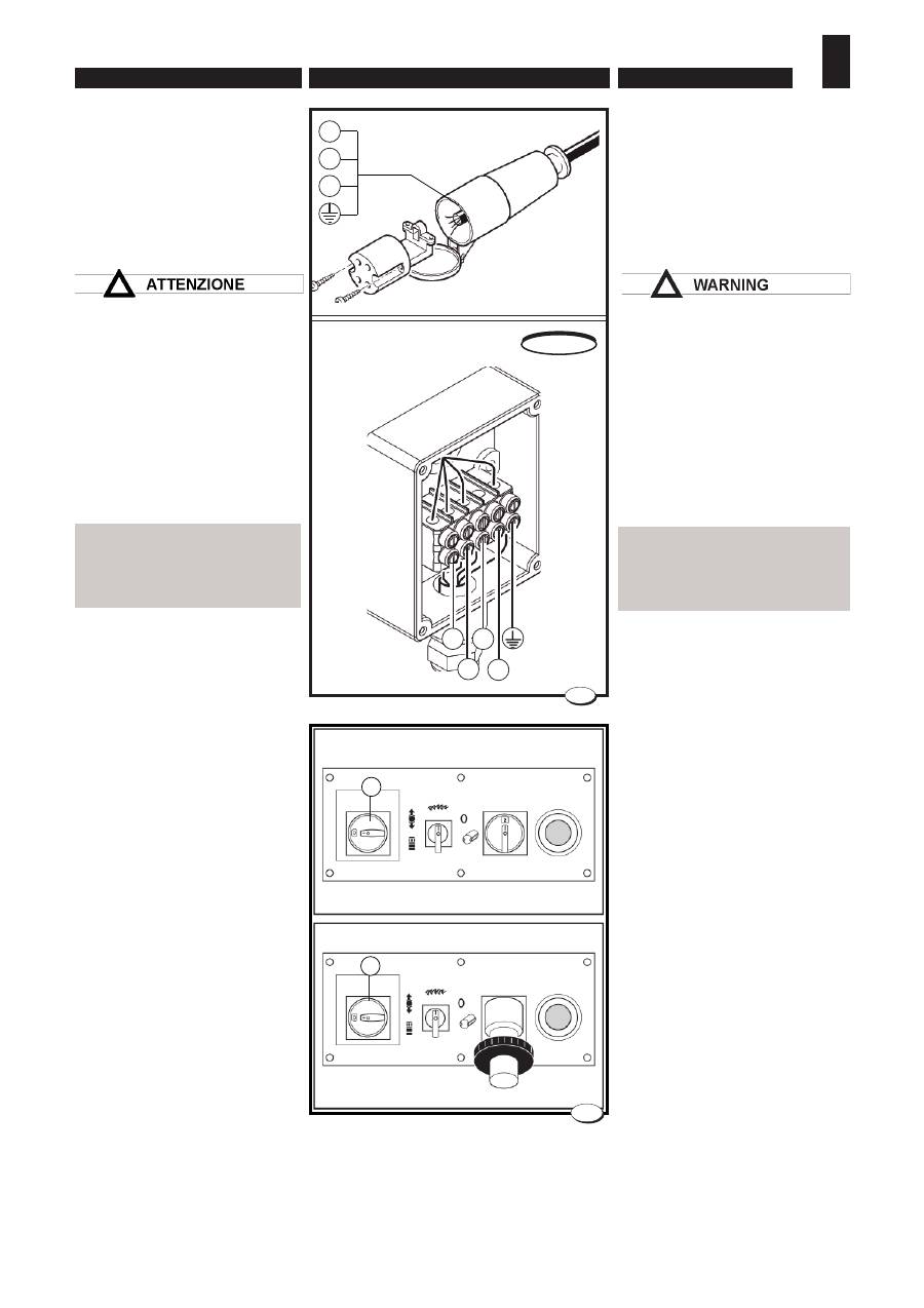
8.
GUIDA ALLA RICERCA DEI GUASTI • TROUBLE - SHOOTING GUIDE
ENGLISH
ITALIANO
- 144 -
040_0103_1.tif
2
A
L1
L2
L3
025_008_0 / 026_036_0 .tif
1
L1
L2
L3
N
USA-CANADA
A
8.1. EVENTUALI INCONVE-
NIENTI, CAUSE, RIMEDI
Per qualsiasi informazione o pro-
blema contattare il concessionario
di zona o il nostro centro assisten-
za (vedi recapito telefonico pag.3).
Gli interventi da eseguire devono
essere effettuati da personale
tecnico specializzato.
Prima di accedere all'interno
del quadro elettrico, mettere a
zero O l'interruttore generale
posto a monte della macchina,
e chiuderlo con l'aiuto di un
lucchetto.
Inconveniente
ALL'ACCENSIONE LA
MACCHINA NON PARTE
O SI FERMA DURANTE LA
LAVORAZIONE
Causa
1
- Mancanza di energia elettrica
su una o più fasi.
2
- Fusibili interrotti (Versione USA
e CANADA).
3
- Emergenza inserita.
4
- Termico di protezione
A
(fi g. 2) inserito a causa di:
- un eccessivo assorbimento
di corrente dovuto ad un uso
improprio della macchina
(lavoro troppo pesante in
rapporto alla potenza del
motore).
- sezione del cavo insuffi ciente
in rapporto alla potenza del
motore (vedi riferimenti col-
legamento elettrico cap.4)
- caduta di tensione dovuta alla
eccessiva lunghezza del cavo
di alimentazione.
- parte elettrica in corto circuito
5
- Micro di sicurezza inserito
(Versione USA e CANADA).
Rimedi
8.1. TROUBLES - CAUSES
-WHAT TO DO
For any information or problem
contact your area dealer or our
technical service centre (see
telephone number on Page 3).
The necessary interventions
must be carried out by special-
ised technical personnel.
Before accessing the electric
panel, set the main switch at the
top of the machine to O and lock
it with a padlock.
Trouble
THE MACHINE DOES NOT
START WHEN IT IS TURNED
ON OR STOPS DURING A
MACHINING CYCLE
Cause
1
- Lack of line voltage.
2
- Fuses blown
(U.S.A. and
CANADA version).
3
- Emergency on.
4
- Overload switch
A
(fig. 2)
triggered because:
- excessive current absorption
caused by improper machi-
ne use (work too heavy in
relation to motor power).
- cable too small for motor po-
wer (see electrical connec-
tion specifi cations chap.4)
- drop in voltage due to exces-
sive length of power supply
cable.
- short circuit in the electric
system.
5
- Safety microswitch on
(U.S.A.
and CANADA version).

- 145 -
8.
STÖRUNGSSUCHE • GUIDE POUR LA RECHERCHE DES ANOMALIES
GUIA PARA BUSCAR LAS AVERIAS
FRANÇAIS
DEUTSCH
ESPAÑOL
8.1.
ВОЗМОЖНЫЕ
НЕИСПРАВНОСТИ, ИХ
ПРИЧИНЫ И УСТРАНЕНИЕ
За информацией или помощью
обращайтесь к местному дилеру
или в наш сервисный центр (см.
телефоны на стр. 3).
Работы должны выполняться
квалифицированным
техническим персоналом.
Перед началом ремонтных
работ в электрощите перевести
в положение O выключатель
питания, установленный на линии
перед станком и закрыть его на
ключ.
Неисправность
СТАНОК НЕ ЗАПУСКАЕТСЯ
ПРИ ВКЛЮЧЕНИИ ИЛИ
ОСТАНАВЛИВАЕТСЯ ВО
ВРЕМЯ РАБОТЫ
Причина
1 - Отсутствует напряжение на
одной или нескольких фазах.
2 - Перегорели предохранители
(исполнение по нормам США
и Канады).
3 - Нажата аварийная кнопка.
4 - С р а б о т а л
з а щ и т н ы й
выключатель A (рис. 2) по одной
из следующих причин:
- перегрузк а по ток у из-за
ненадлежащего использования
станк а (слишком тяжелая
обработка для имеющейся
мощности двигателя).
- сечения кабеля недостаточно
для имеющейся мощности
двигателя (см. инструкции по
электрическому подключению
в главе 4).
- падение напряжения из-за
слишк ом большой длины
кабеля питания.
- короткое замыкание в одной из
цепей.
5 - С р а б о т а л
к о н ц е в о й
выключатель безопасности
(исполнение по нормам США
и Канады).
8.1. DEFAUTS, CAUSE, RE-
MEDES
Pour toute information ou problème,
contacter le concessionnaire de
zone ou notre service après-vente
(voir coordonnées téléphonique
page 3).
Les interventions à exécuter doivent
être effectuées par un personnel
technique spécialisé
Avant d’accéder à l’intérieur de
l’armoire électrique, mettre à zéro
O l’interrupteur général situé en
amont de la machine, et la ver-
rouiller.
Defaut
LA MACHINE NE SE MET PAS
EN MARCHE OU S'ARRETE
PENDANT L'USINAGE
Cause
1
- Manque de tension d’alimenta-
tion.
2
- Fusibles grillés
(version U.S.A. et
CANADA).
3
- Poussoir d’urgence activé.
4
-
Thermique de protection
A
(fi g.
2) enclenché à cause de
:
-
une absorption excessive
de courant due à un usage
impropre de la machine (usi-
nage trop lourd par rapport à
la puissance du moteur).
- section du câble insuffi sante
par rapport à la puissance du
moteur (voir informations bran-
chement électrique Ch 4)
- chute de tension due à la
longueur excessive du câble
d’alimentation.
- partie électrique en court-cir-
cuit.
5
- Microcontact de sécurité enclen-
ché
(version U.S.A. et CANADA).
Remedes
8.1. POSIBLES INCONVENIEN-
TES, CAUSAS, REMEDIOS
Para cualquier tipo de información o
problema contacte con su distribui-
dor en la zona o su centro de servicio
técnico (ver número de teléfono en
la Página 3).
Las operaciones a realizar deben
ser efectuadas por personal técnico
especializado.
Antes de acceder al interior del
cuadro eléctrico, llevar el interruptor
general situado al inicio de la má-
quina a la posición O y trabarlo con
candado.
Inconveniente
EN EL ENCENDIDO LA MAQUI-
NA NO ARRANCA
O SE PARA DURANTE EL TRA-
BAJO
Causa
1
- Falta de tensión de alimentación.
2
- Fusibles interrumpidos
(versión
U.S.A. y CANADA).
3
- Emergencia activada.
4
- Térmico de protección
A
(fi g. 2)
activado por causa de:
- una excesiva absorción de co-
rriente debido a un uso impropio
de la máquina (trabajo dema-
siado pesado con respecto a la
potencia del motor).
- sección del cable insufi ciente
con respecto a la potencia del
motor (véanse las referencias
conexión eléctrica cap.4)
- caída de tensión debida a la
excesiva longitud del cable de
alimentación.
- parte eléctrica en cortocircuito.
5
-Microinterruptor de seguridad
conectado (versión U.S.A. y
CANADA).
Remedios
ВНИМАНИЕ

8.
GUIDA ALLA RICERCA DEI GUASTI • TROUBLE - SHOOTING GUIDE
ENGLISH
ITALIANO
- 146 -
What to do
1
- With a tester check that there
is power on the three phases
L
(Fig. 1)
2
- Check that the fuses are undam-
aged and, if necessary, replace
them (the fuses are positioned
inside the electrical equipment).
3
-
Disconnect the emergency
button, by turning it clockwise.
4
- Put the problem right, wait for
the overload switch to cool down
and start the machine up again.
5
- Check that the planing table is
in the correct position and the
blade and spindle access guard
door is as shown in chapter 2.
Trouble
THE MOTOR TURNS BUT THE
TOOL STOPS WHEN IT
COMES INTO CONTACT
WITH THE PIECE TO MA-
CHINE
Cause
1
- The motor belt is loose or ruined.
What to do
1
- Tighten the belt or change it fol-
lowing the instructions in Chap.
7.
1
- Verifi care con un tester che ci
sia tensione sulle tre fasi
L
(fi g.
1).
2
- Controllare l'integrità dei fusibili
ed eventualmente sostituirli (i
fusibili sono posizionati all'in-
terno dell'apparecchiatura
elettrica).
3
-
Disinserire il pulsante d'emer-
genza ruotandolo in senso
orario.
4
- Risolvere la causa, attendere
che la termica si raffreddi e
riavviare la macchina.
5
- Verifi care il corretto posiziona-
mento della piana fi lo, sportello
protezione accesso lama e
toupie come indicato nel cap.2.
Inconveniente
IL MOTORE GIRA MA
L'UTENSILE SI FERMA
QUANDO È A CONTATTO
CON IL PEZZO DA
LAVORARE
Causa
1
- La cinghia del motore si è al-
lentata o è rovinata.
Rimedi
1
- Tensionare la cinghia o cam-
biarla seguendo le istruzioni
del cap.7.

- 147 -
8.
STÖRUNGSSUCHE • GUIDE POUR LA RECHERCHE DES ANOMALIES
GUIA PARA BUSCAR LAS AVERIAS
FRANÇAIS
DEUTSCH
ESPAÑOL
Способы устранения
1 - П р о в е р и т ь
т е с т е р о м
напряжение на трех фазах L
(рис. 1).
2 - П р о в е р и т ь с о с т о я н и е
п р е д о х р а н и т ел е й и п р и
необходимости заменить их
(предохранители находятся
внутри блока автоматики).
3 - В ы с в о б од и т ь а в а р и й н у ю
кнопку, повернув ее по часовой
стрелке.
4 - Устранить проблему, дождаться
охлаждения выключателя и
повторно включить станок.
5 - П р о ве р и т ь п р а в и л ь н о с т ь
расположения фуговальных
столов, дверцы доступа к пиле
и дверцы фрезерного узла, как
описано в главе 2.
Неисправность
ВАЛ ДВИГАТЕЛЯ ВРАЩАЕТСЯ,
НО ИНСТРУМЕНТ
ОСТАНАВЛИВАЕТСЯ ПРИ
КОНТАКТЕ С ЗАГОТОВКОЙ
Способы устранения
1 - Ослаблен или поврежден
приводной ремень
Способы устранения
1 - П од т я н у т ь и л и з а м е н и т ь
ремень, следуя инструкциям
главы 7.
1
- Contrôler, avec un testeur, que
la tension se trouve bien sur les
trois phases
L
(fi g. 1).
2
- Contrôler le bon état des fusibles
et, le cas échéant, les rempla-
cer (les fusibles sont placés à
l’intérieur de l’armoire électrique).
3
-
Désactiver le poussoir d’urgence
en le tournant dans le sens ho-
raire.
4
-
Résoudre le problème, attendre
que le thermique refroidisse et
relancer la machine.
5
- Vérifi er le positionnement de la
dégauchisseuse, le portillon qui
protège l'accès à la lame et la
toupie, comme l'indique la rubr.
2.
Defaut
LE MOTEUR TOURNE MAIS
L’OUTIL S’ARRETE LORSQU’IL
EST EN CONTACT AVEC LA
PIECE A USINER
Cause
1
- La courroie du moteur s’est
détendue ou est abîmée.
Remedes
1
- Tendre la courroie ou la rempla-
cer en suivant les instructions
fournies au chap. 7.
1
- Mediante un comprobador con-
trolar la presencia de tensión
sobre las tres fases
L
(fi g.1).
2
- Controlar la integridad de los
fusibles y sustituirlos si es nece-
sario (los fusibles se encuentran
situados dentro de la instalación
eléctrica).
3
-
Desactivar el pulsador de emergen-
cia girándolo en el sentido de las
agujas del reloj.
4
- Solucionar la causa, esperar a
que la térmica se enfríe y volver
a arrancar la máquina.
5
- Comprobar el correcto posicio-
namiento de la mesa refrenta-
dora, de la puerta protección
acceso hoja y toupie conforme
a las explicaciones del cap.2.
Inconveniente
EL MOTOR GIRA PERO
LA HERRAMIENTA SE
DETIENE CUANDO ENTRA EN
CONTACTO CON LA PIEZA A
ELABORAR
Causa
1
- La correa del motor está fl oja o
deteriorada.
Remedio
1
- Tensar la correa o cambiarla
siguiendo las instrucciones del
punto 7.
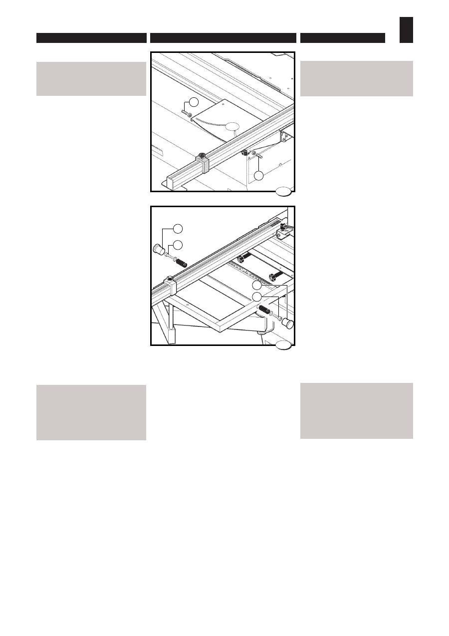
8.
GUIDA ALLA RICERCA DEI GUASTI • TROUBLE - SHOOTING GUIDE
ENGLISH
ITALIANO
- 148 -
040_069_1.tif
3
B
B
040_070_1.tif
4
B
A
B
A
Inconveniente
LA RIGA TELESCOPICA
NON SI POSIZIONA
CORRETTAMENTE A 90°.
Causa
1
- Le battute nel telaio non sono
regolate.
Rimedi
1
- Togliere i due tappi
A
e agire
sulle viti
B
di registrazione
(fi g. 3-4).
Inconveniente
IL PANNELLO SCORRE
A FATICA DURANTE IL
TAGLIO (È STRETTO FRA
GUIDA E LAMA)O NON
VIENE TAGLIATO CON I LATI
PARALLELI.
Causa
1
-
La guida per tagli paralleli
si è sregolata (deve essere
parallela alla lama con una
leggera apertura di uscita di
0,10 mm).
Rimedi
1
- Rivolgersi al nostro centro assi-
stenza (vedi recapito telefonico
pag.3).
Trouble
THE TELESCOPIC RULER
DOES NOT POSITION
CORRECTLY AT 90°
Cause
1
- The end-stops in the frame are
not adjusted.
What to do
1
- Remove the two caps
A
and
turn the adjusting screws
B
(Fig.
3-4).
Trouble
THE PANEL SLIDES WITH DIF-
FICULTY DURING CUTTING
(IT IS TIGHT BETWEEN THE
FENCE AND THE BLADE) OR
IS NOT CUT WITH SIDES PA-
RALLEL.
Cause
1
-
The parallel cutting fence
is badly positioned (this must
be parallel with the blade with a
slight opening exit of 0.10 mm).
What to do
1
- Contact our technical service
(see telephone number on
Page 3).

- 149 -
8.
STÖRUNGSSUCHE • GUIDE POUR LA RECHERCHE DES ANOMALIES
GUIA PARA BUSCAR LAS AVERIAS
FRANÇAIS
DEUTSCH
ESPAÑOL
НЕИСПРАВНОСТЬ
НАРУШЕНО ПОЛОЖЕНИЕ 90°
ПОПЕРЕЧНОЙ ЛИНЕЙКИ.
Причина
1 - У п о р ы
н а
р а м е
н е
отрегулированы.
Способы устранения
1 - Снять пару заглушек A и
отрегулировать упоры винтами
B (рис. 3-4).
Неисправность
ДЛЯ ПОДАЧИ ПЛИТЫ ПРИ
РАСПИЛЕ ТРЕБУЕТСЯ
СЛИШКОМ БОЛЬШОЕ УСИЛИЕ
(ПЛИТА ЗАЖИМАЕТСЯ
МЕЖДУ ЛИНЕЙКОЙ И
ПИЛОЙ) ИЛИ НАРУШЕНА
ПАРАЛЛЕЛЬНОСТЬ РАСКРОЯ
НА ПРОТИВОЛЕЖАЩИХ
СТОРОНАХ.
Причина
1- Н а р у ш е н а н а с т р о й к а
параллельной линейки (она
должна иметь небольшое
расхождение за пилой - 0,10
мм).
Способы устранения
1 - Обратиться в сервисный центр
изготовителя (см. телефонные
номера на стр. 3).
Defaut
LA LAME DE L’INCISEUR SE
DEPLACE.
Cause
1
- La goupille de blocage
A
(fi g.3-4)
est desserrée.
Remedes
1
- Régler le ciseleur comme décrit
au chap. 5, puis serrer la vis
A
(fi g.3 - 4).
Defaut
LE PANNEAU COULISSE DIF-
FICILEMENT PENDANT LA
COUPE (IL EST SERRE ENTRE
LA GLISSIERE ET LA LAME)
OU LA COUPE DE SES COTES
N’EST PAS PARALLELE.
Cause
1
- La glissière, pour les coupes pa-
rallèles, s’est déréglée (elle doit
être parallèle à la lame avec une
légère ouverture de sortie de 0,10
mm).
Remedes
1
-
Contacter notre service après-
vente (voir coordonnées télépho-
niques page 3).
FRANÇAISDEUTSCH
Inconveniente
LA HOJA ENTALLADOR PIERDE
SU POSICIÓN.
Causa
1
-
La espiga de bloqueo
A
(fi g.
3-4) está fl oja.
Remedio
1
-
Ajustar el tallador como se
describe en el cap. 5 y apretar la
tuerca
A
(fi g.4).
Inconveniente
EL PANEL SE DESPLAZA
CON DIFICULTAD DURANTE
EL CORTE (ESTÁ SITUADO
ENTRE GUÍA Y HOJA) O NO ES
CORTADO CON LOS LADOS
PARALELOS.
Causa
1
-
La guía para cortes parale-
los se ha desregulado (debe estar
paralela a la hoja, con una ligera
apertura de salida de 0,10 mm).
Remedio
1
-
Contacte con nuestro ser-
vicio técnico (ver número de
teléfono en la Página 3).

