JUN-AIR 3 series: инструкция
Раздел: Техника
Тип:
Инструкция к JUN-AIR 3 series
Operating manual
Bruksanvisning
Istruzioni di servizio
Manual de utilização
РУКОВОДСТВО ПО ЭКСПЛУАТАЦИИ
Instrukcja obsługi
Compressor
Model 3 motor / 3-4 / 6 motor / 6-4 / 6-15 / 6-25
12-25 / 12-40 / 18-40 / 24-40 / 36-150


Operating manual ...................................................................................................................................5
Bruksanvining..........................................................................................................................................8
Instruzioni di servizio ............................................................................................................................ 11
Manual de utilização ............................................................................................................................. 14
СОДЕРЖАНИЕ
.................................................................................................................................... 17
Instrukcja obsługi
...................................................................................................................................20
Technical data .......................................................................................................................................2
Tekniska data ........................................................................................................................................2
Dati tecnici.............................................................................................................................................2
Dados técnicos .....................................................................................................................................2
ТЕХНИЧЕСКИЕ ДАННЫЕ
...................................................................................................................2
Dane techniczne
.....................................................................................................................................23
Spare parts............................................................................................................................................0
Reservdelslista......................................................................................................................................0
Pezzi di ricambio .. ................................................................................................................................0
Peças de reposição ..............................................................................................................................0
ЗАПАСНЫЕ ЧАСТИ
.............................................................................................................................0
Części zamienne
....................................................................................................................................30
Drawings ...............................................................................................................................................
Ritningar ................................................................................................................................................
Disegni .. ...............................................................................................................................................
Diagramas ............................................................................................................................................
ЧЕРТЕЖИ
............................................................................................................................................
Schematy złożeniowe
.............................................................................................................................33
Pictures/illustrations ..............................................................................................................................5
Bilder/illustrationer ................................................................................................................................5
Figure/illustrazioni.. ...............................................................................................................................5
Figuras/ilustrações ...............................................................................................................................5
РИСуНКИ / ИллюСТРАцИИ
..............................................................................................................5
Ilustracje.................................................................................................................................................53
GB
SE
IT
PT
RU
PL


5
Information
Please note that you can find the pictures and illustrations
we are referring to on page 5.
Warning
·
Unless directions are followed and original spare parts
used, physical injury or property damage may result.
·
Protect compressor against rain, moisture, frost, and dust.
·
Compressor is only suitable for installations with the nomi
nal voltage stated on the motor plate.
·
Do not in any way block or prevent the normal functioning of
the safety valve on the receiver.
·
Only connect pneumatic equipment suitable for the max.
pressure indicated.
·
Do not operate compressor at ambient temperatures
exceeding 5°C/95°F or falling below 0°C/2°F.
·
Do not touch compressor motor during operation as there is
a risk of burn due to high temperatures.
·
Do not direct air flow at head or body.
·
When a flammable liquid is sprayed, there may be danger of
fire or explosion, especially in closed rooms.
·
Always keep the compressor out of reach of children.
Guarantee
Provided that the operational instructions have been carried out,
your JUNAIR compressor is guaranteed against faulty material
or workmanship for 2 years.
The air receiver is guaranteed for 5 years.
The guarantee does not cover damage caused by violence,
misuse, incorrect repairs or use of wrong oil and unoriginal
spare parts.
Costs of transportation of parts/equipment are not covered by
the guarantee.
JUNAIR’s Conditions for Sale and Delivery will generally apply.
JUNAIR International A/S reserves the right to change
technical specifications/ constructions.
How to operate the JUN-AIR compressor
Your JUNAIR compressor is very easy to operate. Observe
the following simple instructions and you will get many years’
service from your compressor.
1. Visually inspect unit for shipping damage, contact your
supplier immediately if you think the unit may have been
damaged.
2. Always keep the compressor in a vertical position during
use and transportation.
. Place the compressor in a dustfree, dry and cool, yet
frostfree, room. Do not install in a closed cupboard, unless
adequate openings for ventilation are available (fig. 1).
Ensure that the compressor stands firmly on the floor.
4. Replace the cap on the air intake tube with the intake filter
(fig. 2).
5. Connect pneumatic equipment.
Important!
The compressor oil may be aggressive towards
certain gasket materials used in pneumatic
equipment. We recommend Teflon, Viton, etc.. Do not
use polycarbonate filter bowls. Contact your local
JUN-AIR distributor if you need further information.
6. Plug the compressor into an outlet switch of nominal voltage
and ensure that fusing is adequate (see Technical Details).
7. Start the compressor using the 0/1 switch on the pressure
switch (fig. ). The compressor will automatically switch off
at the preset pressure. If the motor does not start it may
be due to pressure in the receiver, and the motor will then
start automatically when the pressure reduces to approx. 6
bar/87 psi.
8. Always keep the compressor in a vertical position as oil
may run out of the intake filter. During transportation, mount
the cap on the inlet. Mechanical noise from the compressor
in connection with handling does not have any functional
importance.
Warning!
Never mount the transportation cap on oil-lubricated
compressors while there is still pressure in the
compressor & pressure vessel, as this may cause a
pressure build up in the motor housing.
9. Adjustment of pressure (fig. 4):
A: Max. pressure adjustment (cutout)
B: Differential adjustment (cutin)
The cutin pressure (normally 6 bar) is set by adjustment
of differential screw B. Turn clockwise to reduce cutin
pressure.
The cutout pressure is set by even adjustment of the two
screws A. (Cutin pressure + differential = cutout pressure).
Turn clockwise to increase cutout pressure.
The switch is normally factory set for operation at 68 bar
(approx. 90120 psi).
10. Adjustment of CONDOR 416 pressswitch (fig. 4a)
The cutout pressure (normally 16 bar) is set by adjustment
of maximum pressure screw. (Cutin pressure + different
pressure = cutout pressure). Turn clockwise to increase
cutout pressure.
The cutin pressure (normally 14 bar) is set by adjustment
of differential screw. Turn clockwise to reduce cutin
pressure.
The switch is normally from the factory set for operation at
1416 bar.
Technical details
The max. operation of the compressor is 50% of the operation
time, and the max. operation time is 15 min. at 8 bar/120 psi in
each cycle. Consequently, 15 min. standstill is required before
the next start. For tables with technical data and performance
curves, see page 2.
Operating manual
Operating manual
GB
6
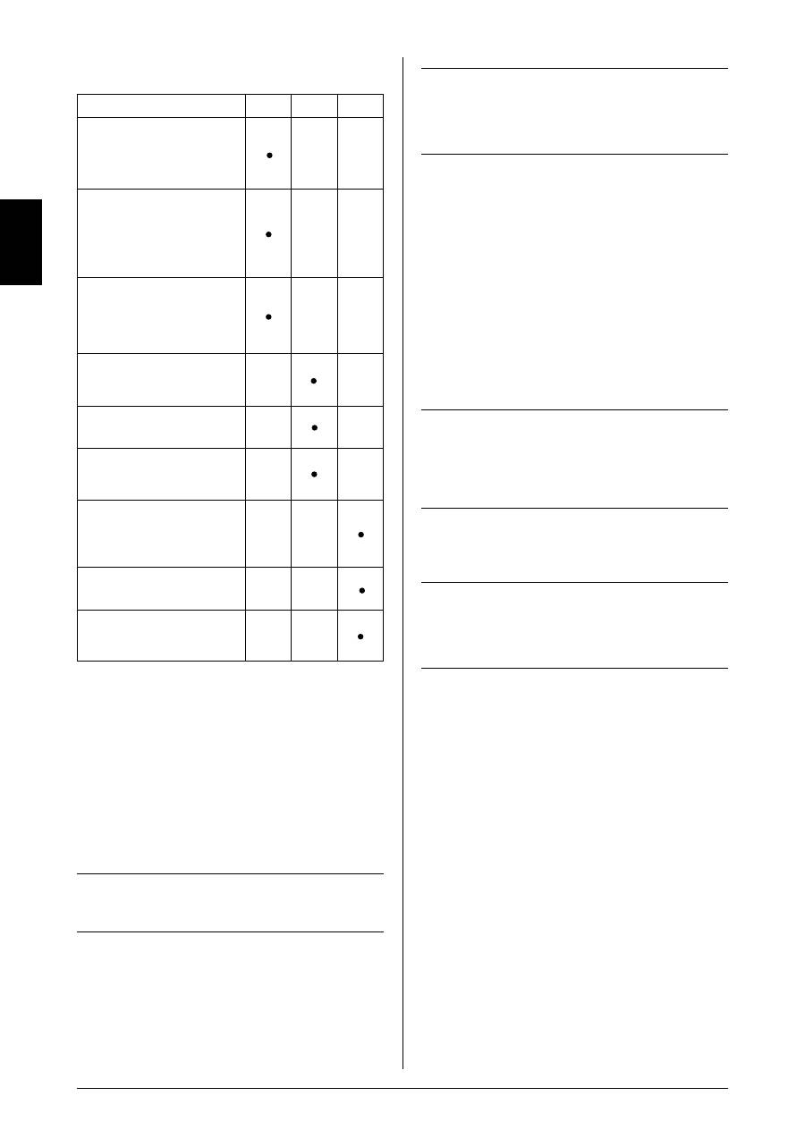
Preventive compressor maintenance
Weekly
Monthly Annually
Check oil level. During standstill
the correct level is between the
maximum and the minimum
indications. Use only genuine SJ27
synthetic oil. Do not overfill (fig. 5).
Drain condensate from air receiver
(at a pressure of max. 2 bar/0
psi) (fig. 6). If fitted with auto drain,
this will take place automatically,
however, drain bottle has to be
emptied.
If compressor is fitted with outlet
filter, check and empty for water by
pressing the black button. If fitted
with auto drain, this will take place
automatically.
Check compressor, air tubes and
equipment for leaks, and check the
pumping time.
Inspect and replace intake filter, if
necessary.
Clean the compressor with a soft,
damp cloth. Dust and dirt prevent
cooling.
Check the Oring in the nonreturn
valve and replace if necessary (fig. 10)
Note! Empty receiver of air before
dismounting.
Check filter and filter elements for
optimum efficiency.
Test the safety valve by gently
pulling the ring with pressure in the
receiver (fig. 7).
Oil change
In connection with repair of model 6 motors, e.g. change
of valve plate or other internal motor parts or in case the
compressor is installed in a very dusty environment, oil change
may be necessary. Proceed as follows:
1. Remove the ribbed cover by loosening the 4 screws (fig. 8).
2. Tilt the motor towards side with outlet and at the same time
hold the internal motor parts in place with hand. Pour all oil
out of housing (fig. 8). In case of dirt particles at the bottom
of the motor housing, clean with a rag.
Note!
Waste oil is to be handled according to the
environmental rules in force in the country.
. Tilt the motor back and fill with SJ27 oil (approx. 0.75l) (fig. 8).
4. Clean the edge of casing and cover. Check the Oring of the
ribbed cover.
5. Replace the ribbed cover and check during operation that
the Oring is placed correctly to ensure a 100% tight closing
between housing and cover.
Important!
Always use SJ-27 oil as other types of oil may cause
serious mechanical damage to the compressor.
Consequently, the warranty only applies if SJ-27 oil is
used.
Check the pumping time
The pumping time indicates the condition of the compressor
provided that there
are no leaks in the system where the compressed air may leak.
Test the compressor as follows:
1. Empty the air receiver of compressed air (the pressure
gauge shows 0 bar).
2. Close the outlet on the air receiver and check that the drain
cock is closed.
. Start the compressor and note how long it takes until it
switches off.
Make sure that the pressure in the air receiver is 8 bar/120
psi as deviations may indicate the wrong results (see
technical details).
Important!
Always test the compressor when cold as the time
indicated refers to the pumping time of a cold
compressor. The pumping time of a warm compressor
is much longer and consequently, the result would be
misleading.
Fault finding and repair
Important!
Switch off and isolate from electrical supply before
removing any parts from the compressor.
Empty air receiver of air before dismantling any parts
of compressor unit’s pressure system.
1. Compressor does not start:
a) No power from mains. Check fuses and plug.
b) Breakage or loose joints in electrical connections.
c) The starting relay is defective. Contact your JUNAIR
distributor.
d) The pressure switch is defective and does not switch on
the compressor.
e) The thermal protection has switched off the compressor
due to overheating. When cooled the compressor will
automatically turn on at a suitable operation tempera
ture. Go through the points in section 4.
f) Pressure in the air receiver is too high for activation
of the pressure switch. The pressure switch makes
circuit only when pressure has dropped to preset
start pressure. Empty the receiver.
g) The compressor has not been unloaded and there is
back pressure on the piston. Dismount and check
unloader valve (fig. 9). The back pressure may be
due to a leaking nonreturn valve causing the
compressed air in the receiver to leak back into the
compressor motor. Dismount the nonreturn valve and
clean or change Oring (fig. 10).
h) Capacitor defective.
Operating manual
GB
7
2. Compressor operates, but pressure does not increase
in tank (or increases too slowly):
a) The cap on the intake tube has not been removed and
replaced by the intake filter (fig. 2).
b) Intake filter is clogged. Replace.
c) Leaks in fittings, tubes or pneumatic equipment. Check
with soapy water. Pressure drop is not to exceed 1 bar
per hour.
d) Clogged nonreturn valve or pressure pipe. Clean or
replace the parts (fig. 10).
e) Air leaks from the unloader valve when the compressor
is operating. Check or replace the unloader valve (fig. 9).
f) Defective valve plate. Contact your JUNAIR distributor.
3. Loud noise from compressor:
a) Most likely broken suspension spring(s). Replace the
spring and ensure that motor position is horizontal.
b) The internal pressure pipe touches the rib cover or
the cylinder block. Dismount the rib cover and bend the
pressure pipe away.
4. Compressor gets very hot and/or uses a lot of oil:
a) Incorrect oil level. The level must appear in the oil level
glass (fig. 5).
b) Wrong oil has been filled in the compressor. Use only
SJ27 synthetic lubricant which has the correct viscosity.
c) Leaks. See point 2c.
d) Clogged intake filter. See point 2b.
e) Too high ambient temperature. Do not install the
compressor in a cabinet unless adequately ventilated
(fig. 1).
f) The compressor is overloaded (i.e. it is operating more
than 50% of the operation time). Contact your JUNAIR
distributor.
5. Compressor starts when no air is being used:
a) Leaks. See point 2c.
6. Compressor starts and stops more frequently than
usual:
a) Condensate in the air receiver. Empty the receiver by
means of the drain cock (fig. 6).
b) Leaks. See point 2c.
Pressure vessel
Pressure tested at:
425 liter:
4050 liter:
Directions for use
Application
Receiver for compressed air.
Receiver specifications See name plate.
Installation
Tubes, etc. must be made of suitable
materials.
Placement
Observe the working temperature of
the receiver.
Ensure that sufficient room for
inspection/maintenance is available
in a horizontal position.
The receiver must be kept in a
horizontal position.
Corrosion protection
The surface treatment must be
maintained as required.
Internal inspection at least every
5 years.
Drain moisture at least once a week.
Alternation/repair
No welding must be made on
pressurized parts.
Safety valve
Ensures that PS will not be exceeded.
Never adjust to a higher pressure
than PS.
The capacity of the valve must be
calculated in accordance
with the volume of air supplied by
the compressor.
(PS = Maximum working pressure
of the receiver)
Declaration of Conformity
NOTE: The declaration of conformity is only valid for units
operating at 20 V/50 Hz, x400 V/50 Hz, 12 V DC or 24 V DC.
The manufacturer, JUNAIR International A/S, declares that the
products mentioned in this manual are in conformity with:
• 87/404/EEC 90/488/EEC 9/68/EEC Council Directive
relating to Simple Pressure Vessels
• 89/92/EEC 91/68/EEC 9/44/EEC 9/68/EEC
Council Directive of Safety of Machinery
• 89/6/EEC Council Directive of Electric Magnetic
Compatibility
• 7/2/EEC Lowvoltage Directive
Flemming Frisch Andersen
Test and Certification Administrator
24 bar
18.3 bar
Operating manual
GB
