Cambridge Audio AZUR 540A: инструкция
Раздел: Бытовая, кухонная техника, электроника и оборудование
Тип: Домашний кинотеатр
Инструкция к Домашнему кинотеатру Cambridge Audio AZUR 540A

azur 540A/640A
Integrated amplifier / HIFI-Verstärker / Amplificateur intégré / Amplificador integrado / Amplificatore
integrato / Geïntegreerde versterker / Integreret forstærker / Встроенный усилитель
User’s manual / Bedienungsanleitung / Mode d'emploi / Manual del usuario / Manuale per l'utente /
Gebruikershandleiding / Brugermanual / Руководство для пользователя

INTRODUCTION
Thank yyou ffor ppurchasing tthis CCambridge AAudio aazur sseries aamplifier. IIt
reduced in size. This has the effect of reducing distortion, increasing
is tthe rresult oof oour mmost eext
ensive eever rresearch aand ddevelopment
dynamics and allowing the bandwidth to be opened up to a massive
program iin oover tthree ddecades oof pproducing hhigh qquality aaudio pproducts.
80kHz, ideal for the new 'better than CD' high bandwidth sources such
We hhope tthat yyou wwill aappreciate tthe rresults aand eenjoy mmany yyears oof
as DVD-Audio and Super Audio CD.
listening ppleasure.
The performance of any amplifier is limited by the dynamic abilities of its
power supply, and for this reason Cambridge Azur amplifiers incorporate
many features, including a low flux toroidal transformer, paralleling of
About tthis aamplifier
the reservoir capacitors and careful use of bypass capacitors, to allow
The design of any purist audio amplifier is mainly centred on two main
the instantaneous clean delivery of charge whenever it is needed. This
areas, the Power Supply and the driver stage's ability to drive the output
ensures an open and natural sound being reproduced and ensures a
stage effectively. We at Cambridge Audio have researched the best
positive response to any dynamics or sudden transients in the signal
possible ways to achieve the highest performance in these areas, at a
being reproduced.
sensible price. The Azur 540A/640A topology uses the same tried and
Particular attention has also been paid to the quality of the passive
tested output devices that Cambridge Audio have used in previous
components which have been carefully chosen for their sonic benefits.
award winning amplifier models, but many hours of research have gone
The Azur 640A in addition uses high grade Polypropylene signal bypass
into the study and development of the preceding stages. This driver
capacitors to improve signal flow and dynamics.
circuitry is essentially a matched differential input pair, loaded by a
current mirror and driven from a transient compensated current source
The Cambridge Audio Azur 540A and 640A amplifiers also incorporate
driving a high beta cascoded voltage gain stage. The thermally
tone controls, which may be switched out of circuit in 'direct' mode for
compensated output stage is setup to inherently give optimum Class AB
the shortest and therefore purest signal path. Other features include
conditions (for greatly reduced cross over distortion caused by dynamic
24k gold plated phono sockets, dual tape loops, pre amp output, a
heating of the output dies). In addition the topology includes a further
headphone socket and a secondary set of high level loudspeaker
improvement to the driver stage consisting of a pure class-A follower to
terminals.
isolate the voltage amplifier transistors from the difficult loading of the
An important feature which has been included as standard on both the
output transistors. This increased current drive to the output stage
540A and 640A is the new innovative Cambridge Audio designed CAP5
combined with a novel transient feed forward circuit doubles the slew
protection system. This consists of a microprocessor which constantly
rate to 40V/uS.
monitors the amplifier providing comprehensive protection against a
Due to critically refined circuit board layouts, careful component
variety of possible faults. This has been achieved without adding any
placement and short signal paths the stability of these amplifiers is
active circuitry into the signal path to degrade the sound or the dynamic
extremely high which allows the compensation components to be
abilities of the amplifier.
2

540A/640A Integrated amplifier
CONTENTS
Cambridge Audio has built up an extensive knowledge base due to
Introduction.................................................................................................2
meticulous listening and tweaking. This attention to detail results in
amplifiers that are totally convincing in the reproduction of both tonal
Safety precautions......................................................................................4
colour and dynamic contrast, deliver a vibrant and fluid performance
with music of all types and are extremely musically involving.
Installation...................................................................................................5
To get the absolute best from this equipment we would encourage you
to use only high quality source components. Of course we particularly
Rear panel connections .............................................................................6
recommend tuners and digital equipment from the Cambridge Audio
range, all of which have been designed to the same exacting standards
Connecting.................................................................................................. 8
as our amplifiers. Many types of loudspeakers were used in the
development of these amplifiers to ensure maximum compatibility with
Operating instructions..............................................................................10
a wide variety of designs.
Interconnects and speaker cables are also something that shouldn't be
CAP5 - Five way protection system...........................................................12
overlooked. Please do not compromise your system's performance by
using poor quality cables to connect source components to your
Troubleshooting.........................................................................................14
amplifier or the amplifiers output to your loudspeakers. A system is only
as good as its weakest link. For this reason we do not include cheap
Specifications............................................................................................14
"freebie" cables with any of our products. Your dealer can supply good
quality Cambridge Audio interconnects and Mordaunt Short/Gale
Limited warranty....................................................................................... 15
loudspeaker cables that will make a noticeable improvement to the
sound quality of your system.
Now wwe iinvite yyou tto ssit bback, rrelax aand eenjoy!
Matthew Bramble
Technical Director
3
SAFETY PRECAUTIONS
Checking tthe ppower ssupply rrating
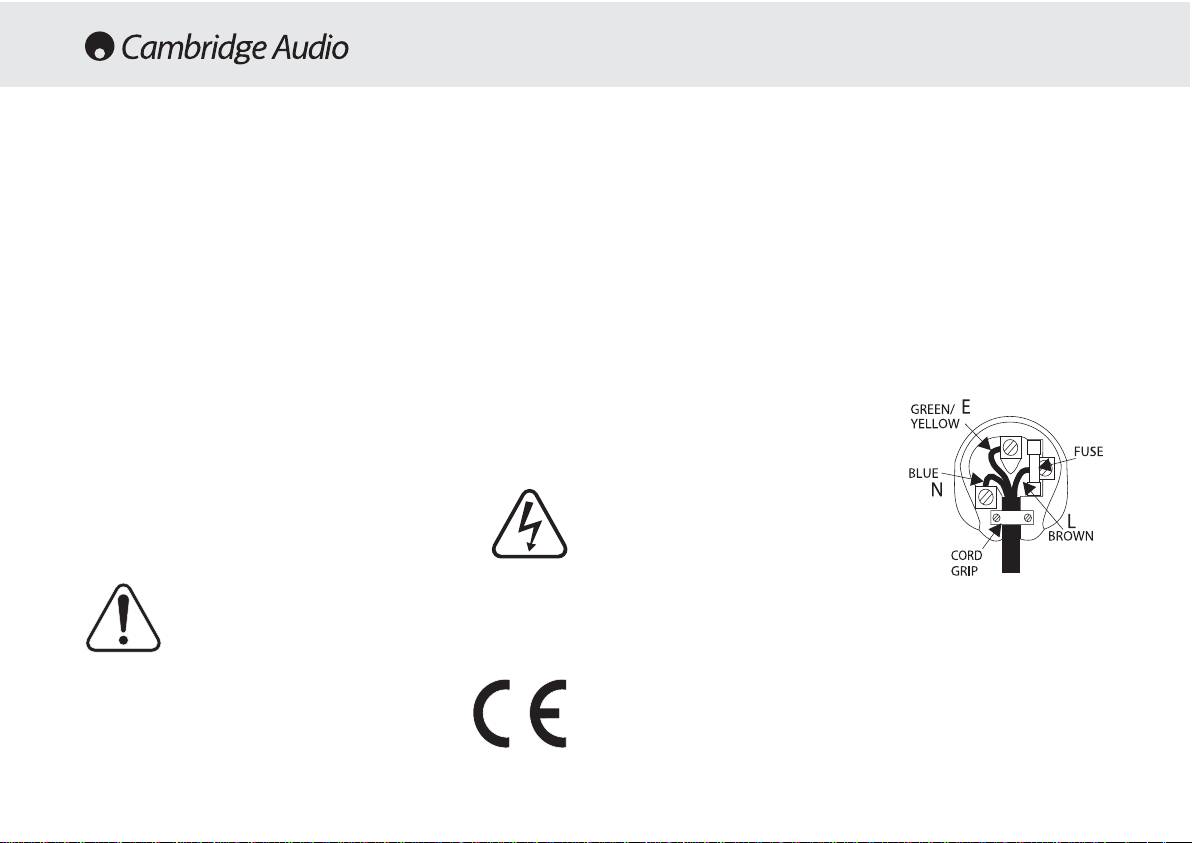
Plug ffitting iinstructions ((UK only)
For your own safety please read the following instructions carefully before
The cord supplied with this appliance is factory fitted with a 13A mains plug fitted
attempting to connect this unit to the mains.
with a 3A fuse inside. If it is necessary to change the fuse, it is important that a 3A
one is used. If the plug needs to be changed because it is not suitable for your
Check that the rear of your unit indicates the correct supply voltage. If your mains
socket, or becomes damaged, it should be cut off and an appropriate plug fitted
supply voltage is different, consult your dealer.
following the wiring instructions below. The plug must then be disposed of safely,
as insertion into a 13A socket is likely to cause an electrical hazard. Should it be
This unit is designed to operate only on the supply voltage and type that is
necessary to fit a 3-pin BS mains plug to the power cord the wires should be fitted
indicated on the rear panel of the unit. Connecting to other power sources may
as shown in this diagram. The colours of the wires in the mains lead of this
damage the unit.
appliance may not correspond with the coloured markings identifying the
This equipment must be switched to Standby mode when not in use, unplugged if
terminals in your plug. Connect them as follows:-
not used for long periods of time, and must not be used unless correctly earthed.
The wire which is coloured BLUE must be
To reduce the risk of electric shock, do not remove the unit's cover (or back). There
connected to the terminal which is marked
are no user serviceable parts inside. Refer servicing to qualified service personnel.
with the letter 'N' or coloured BLACK.
If the power cord is fitted with a moulded mains plug the unit must not be used if
the plastic fuse carrier is not in place. Should you lose the fuse carrier the correct
The wire which is coloured BROWN must be
part must be reordered from your Cambridge Audio dealer.
connected to the terminal which is marked
with the letter 'L' or coloured RED
The lightning flash with the arrowhead symbol within an equilateral
triangle is intended to alert the user to the presence of uninsulated
The wire which is coloured GREEN/YELLOW
'dangerous voltage' within the product's enclosure that may be of
must be connected to the terminal which is
sufficient magnitude to constitute a risk of electric shock to
marked with the letter 'E' or coloured
persons.
GREEN.
The exclamation point within an equilateral triangle is intended to
If your model does not have an earth wire,
alert the user to the presence of important operating and
then disregard this instruction.
maintenance instructions in the service literature relevant to this
appliance.
If a 13 Amp (BS 1363) plug is used, a 3 Amp fuse must be fitted, or if any other
type of plug is used a 3 Amp or 5 Amp fuse must be fitted, either in the plug or
This product complies with European Low Voltage (73/23/EEC)
adaptor, or on the distribution board.
and Electromagnetic Compatibility (89/336/EEC) Directives
when used and installed according to this instruction manual. For
continued compliance only Cambridge Audio accessories should
be used with this product and servicing must be referred to
qualified service personnel.
4

540A/640A Integrated amplifier
INSTALLATION
Please take a moment to read these notes before installing your
To clean the unit, wipe its case with a moist, lint-free cloth. Do not use
amplifier, they will enable you to get the best performance and prolong
any cleaning fluids containing alcohol, ammonia or abrasives. Do not
the life of the product.
spray an aerosol at or near the amplifier.
The unit requires ventilation above and below. Do not situate it on a rug
These units are not user serviceable, never attempt to repair,
or other soft surface and do not obstruct the air inlet and outlet grilles
disassemble or reconstruct the unit if there seems to be a problem. A
on the underside and top cover. Do not place in an enclosed area such
serious electric shock could result if this precautionary measure is
as a bookcase or in a cabinet.
ignored. In the event of a problem or failure, please contact your dealer.
This unit must not be exposed to dripping or splashing water or other
This unit should be installed on a sturdy, level surface. Due to stray
liquids. No objects filled with liquid, such as vases, shall be placed on
magnetic fields turntables should not be located nearby due to
the unit. In the event, switch off immediately, disconnect from the mains
interference.
supply and contact your dealer for advice.
Ensure that small objects do not fall through any ventilation grille. If this
happens, switch off immediately, disconnect from the mains supply and
contact your dealer for advice.
Do not route the power cable so that it can be walked upon or damaged
by other items near it.
Electronic audio components have a running in period of around a week
(if used several hours per day). This will allow the new components to
settle down, the sonic properties will improve over this time.
It is recommended that when bi-amping, the same type power amplifiers
are used.
This amplifier has been designed to be left in Standby mode when not
in use, this will increase the life of the amplifier (this is true with all
electronic equipment). If you do not intend to use this unit for a long
period of time, unplug it from the mains socket.
5
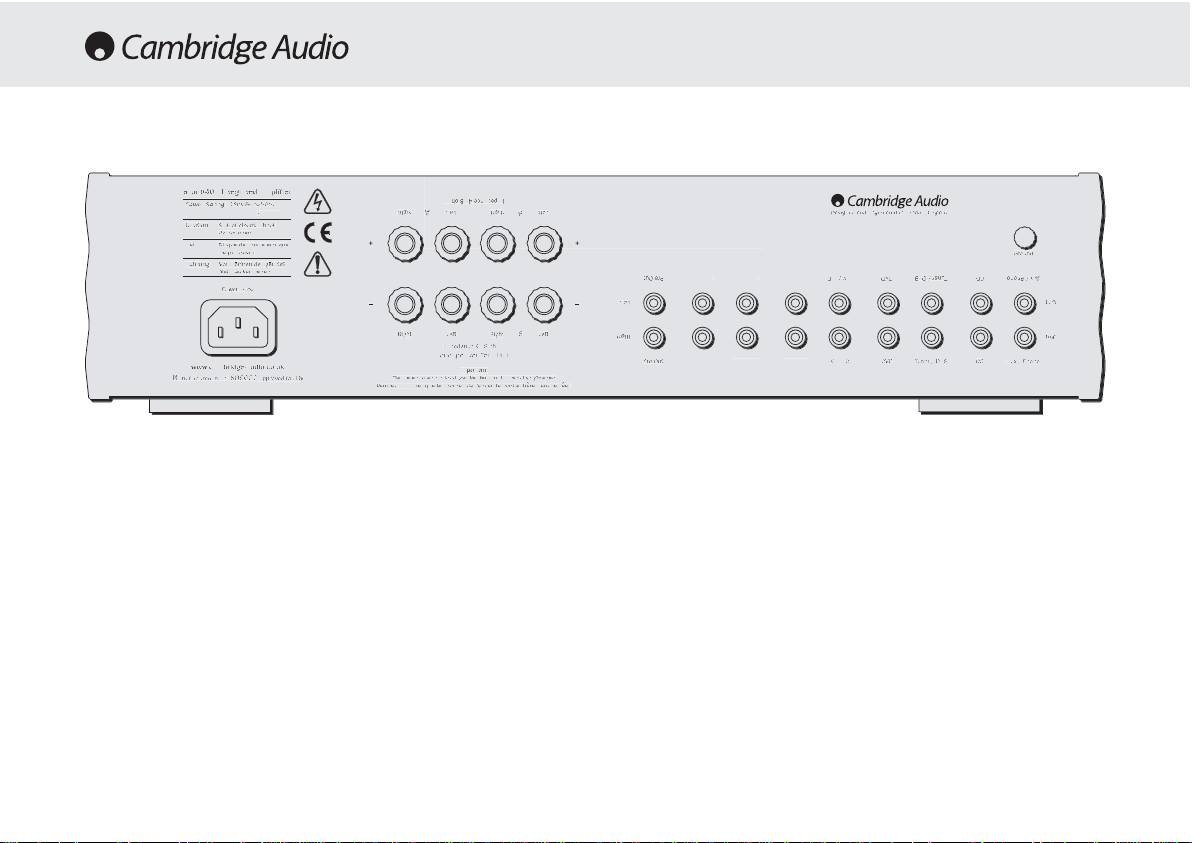
AC power ssocket
Note: TThis aamplifier hhas bbeen ddesigned ffor uuse wwith lloudspeakers tthat
have aa nnominal iimpedance oof bbe
tween 44 aand 88 oohms.
Once you have completed all connections to the amplifier, plug the AC
Power Cable into an appropriate mains socket. The amplifier is now
Please eensure tthat tthe sspeaker tterminals hhave bbeen ttightened
ready for use.
adequately tto pprovide a
a ggood eelectrical cconnection. IIt iis ppossible ffor tthe
sound qquality tto bbe aaffected iif tthe sscrew tterminals aare lloose.
Loudspeaker cconnections
Pre aamp oouts
The 540A and 640A have two sets of Loudspeaker terminals on the rear
panel, speakers A and B. Speakers A are the main speaker terminals,
Connect these sockets to the inputs on an external Power Amplifier(s).
speakers B are the secondary switchable speaker terminals. Connect
the wires from your left channel loudspeaker to the LEFT + & - terminals,
Tape mmon
and likewise the wires from the right channel loudspeaker to the RIGHT
+ & - terminals. In each case the red terminal is the positive output, and
These sockets can be connected to a tape deck or to the analog sockets
the black terminal is the negative input. Care should be taken to ensure
on a MiniDisc or CD recorder. Connect an interconnect cable from the
no stray strands of wire are shorting speaker outputs together. Please
recorder's Line Out sockets to the amplifier's Tape Monitor sockets. This
6
T
ape In
R
ec Out 1
R
ec Out
2
T
ape In
R
ec Out 1
Rec Out
2
M
ax Power Consum
p
tion
:
615W
P
re-Out
Pre-Out
I
mpedance
4
- 8 ohms
Impedance 4 - 8 ohms
L
oudspeaker Terminals
Loudspeaker Terminals
Important
Important
P
lease ensure that loudspeaker terminals are fully tightened
Please ensure that loudspeaker terminals are fully tightened
Veuillez s'assurer que les bornes de l'enceinte sont entierement serreesVeuillez s'assurer que les bornes de l'enceinte sont entierement serrees
I
mpedance 4 - 8 ohms
Impedance 4 - 8 ohms
R
ight
Right
L
eft
Left
R
ight
Right
L
eft
Left
Left
Left
B
B
A
A
R
ight
Right
L
eft
Left
R
ight
Right
B
B
A
A
AV / MD
AV / MD
DVD
DVD
T
uner / DAB
Tuner / DAB
CD
CD
Aux / Phon
o
Aux / Phono
P
re-Out
Pre-Out
AV / MD
AV / MD
D
VD
DVD
Tuner / DAB
Tuner / DAB
C
D
CD
A
ux / Phono
Aux / Phono
R
ight
Right
L
eft
Left
Ri
g
h
t
Right
L
eft
Left
Groun
d
Ground
w
ww.cambridge-audio.co.u
k
www.cambridge-audio.co.uk
M
anufactured in an
Manufactured in an
I
SO900
2
ISO9002
approved facility
approved facility
P
ower A
C
Power AC
D
esigned and Engineered in London, England
Designed and Engineered in London, England
R
isk of electric shoc
k
Risk of electric shock
D
o not ope
n
Do not open
C
aution
Caution
Ris
q
ue de choc electri
q
ue
Risque de choc electrique
Ne
p
as ouvrir
Ne pas ouvrir
Avis
Avis
Vorm offnen des geratesVorm offnen des gerates
N
etzstecker ziehen
Netzstecker ziehen
Achtung
Achtung
a
zur 6
4
0A Integrated Amplifie
r
azur 640A Integrated Amplifier
Power Rating:
Power Rating:
230V AC 50Hz
230V AC 50Hz
REAR PANEL CONNECTIONS

540A/640A Integrated amplifier
monitor doubles up as the standard tape/recording medium input.
Ground cconnection
Note: WWhen cconnecting aa ssource ccomponent tthat hhas bboth aan iinput aand
If you are connecting a turntable to your amplifier then its ground wire
output ii.e. aa ttape rrecorder, tthe o
output oof wwhich sshould aalways bbe
should be attached to this point
connected tto tthe TTape MMon iinput. TThis wwill eeliminate hhowlround iif tthe
wrong iinput cchannel iis sselected.
Tape oout
These sockets can be connected to a tape deck or to the analog sockets
on a MiniDisc or CD recorder. Connect an interconnect cable from the
Tape Out sockets of this amplifier to the recorder's Line In. Please note
that this unit has two tape loops which have identical outputs.
CD/Tuner/DVD/AV/MD iinput ssockets
These inputs are suitable for any 'line level' source equipment such as
CD players, DAB or FM/AM tuners etc.
Aux/Phono iinput ssockets
Connect any 'line level' source equipment to these sockets i.e. CD player
or DAB tuner. Alternatively this particular input can be converted to a
dedicated turntable if desired although to do this a Cambridge Audio
PM01 Phono Module must be fitted. Please contact your Cambridge
Audio dealer who can supply and install a phono stage to your amplifier.
These iinputs aare ffor aanalog aaudio ssignals oonly. TThey sshould nnot bbe
connected tto tthe ddigital ooutput oo
f aa CCD pplayer oor aany oother ddigital ddevice.
7
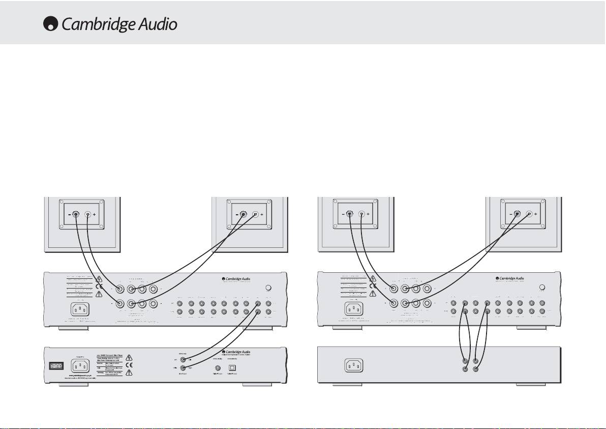
CONNECTING
When designing our amplifiers we have tried to include features that
Tape cconnection
allow you to connect your system in various ways. The inclusion of
features such as PRE-OUT and SPEAKER B connections mean that you
The following diagram shows how to connect the amplifier to a tape
can configure your system depending on your requirements. The
recorder or other source with a record and monitor connection.
following diagrams are designed to make connection easy.
Please note that either of the tape loop outputs can be used (as they are
both the same).
Basic cconnection
The following diagram shows the basic connection of your amplifier to a
CD player and a pair of loudspeakers.
8
M
ax Power
C
onsumption
:
615W
Pre-Ou
t
Pre-Out
Impedance 4 - 8 ohms
Impedance 4 - 8 ohms
Loudspeaker Terminals
Loudspeaker Terminals
Important
Important
P
lease ensure that loudspeaker terminals are fully tightened
Please ensure that loudspeaker terminals are fully tightened
Veuillez s'assurer que les bornes de l'enceinte sont entierement serrees
Veuillez s'assurer que les bornes de l'enceinte sont entierement serrees
Impedance 4 - 8 ohms
Impedance 4 - 8 ohms
R
ight
Right
Left
Left
R
ight
Right
L
ef
t
Left
L
eft
Left
B
B
A
A
Ri
g
h
t
Right
L
eft
Left
Right
Right
B
B
A
A
R
ec Out
1
Rec Out 1
R
ec Out
2
Rec Out 2
T
ape I
n
Tape In
AV / MD
AV / MD
DVD
DVD
Tuner / DAB
Tuner / DAB
CD
CD
A
ux / Phon
o
Aux / Phono
P
re-Out
Pre-Out
R
ec Out 1
Rec Out 1
R
ec Out
2
Rec Out 2
T
ape I
n
Tape In
AV
/
MD
AV / MD
DVD
DVD
Tuner / DAB
Tuner / DAB
C
D
CD
Aux / Phono
Aux / Phono
R
ight
Right
L
ef
t
Left
R
ight
Right
L
eft
Left
G
roun
d
Ground
w
ww.cambridge-audio.co.uk
www.cambridge-audio.co.uk
M
anufactured in an
Manufactured in an
ISO900
2
ISO9002
approved facilit
y
approved facility
P
ower AC
Power AC
D
esigned and Engineered in London, Englan
d
Designed and Engineered in London, England
R
isk of electric shock
Risk of electric shock
D
o not o
p
e
n
Do not open
Caut
i
on
Caution
Risque de choc electriqu
e
Risque de choc electrique
N
e
p
as ouvr
i
r
Ne pas ouvrir
A
v
is
Avis
Vorm offnen des gerates
Vorm offnen des gerates
N
etzstecker ziehe
n
Netzstecker ziehen
A
c
h
tun
g
Achtung
a
zur 6
4
0A Integrated Amplifier
azur 640A Integrated Amplifier
Power Rating:
Power Rating:
230V AC 50Hz
230V AC 50Hz
T
ape In
1
R
ec Out
1
Rec Out
2
T
ape In 1
R
ec Out 1
Rec Out
2
M
ax Power
C
onsumption
:
61
5W
Pre-Ou
tPre-Out
Impedance 4 - 8 ohms
Impedance 4 - 8 ohms
Loudspeaker Terminals
Loudspeaker Terminals
Important
Important
P
lease ensure that loudspeaker terminals are fully tightened
Please ensure that loudspeaker terminals are fully tightened
Veuillez s'assurer que les bornes de l'enceinte sont entierement serrees
Veuillez s'assurer que les bornes de l'enceinte sont entierement serrees
Impedance 4 - 8 ohms
Impedance 4 - 8 ohms
R
ight
Right
Left
Left
R
ight
Right
L
ef
t
Left
L
eft
Left
B
B
A
A
Ri
g
h
t
Right
L
eft
Left
Right
Right
B
B
A
A
AV / MD
AV / MD
DVD
DVD
Tuner / DAB
Tuner / DAB
CD
CD
A
ux / Phon
o
Aux / Phono
P
re-Out
Pre-Out
AV
/
MD
AV / MD
DVD
DVD
Tuner / DAB
Tuner / DAB
C
D
CD
Aux / Phono
Aux / Phono
R
ight
Right
L
ef
t
Left
R
ight
Right
L
eft
Left
G
roun
d
Ground
w
ww.cambridge-audio.co.uk
www.cambridge-audio.co.uk
M
anufactured in an
Manufactured in an
ISO900
2
ISO9002
approved facilit
y
approved facility
P
ower AC
Power AC
D
esigned and Engineered in London, Englan
d
Designed and Engineered in London, England
R
isk of electric shock
Risk of electric shock
D
o not o
p
e
n
Do not open
Caut
i
on
Caution
Risque de choc electriqu
e
Risque de choc electrique
N
e
p
as ouvr
i
r
Ne pas ouvrir
A
v
is
Avis
Vorm offnen des gerates
Vorm offnen des gerates
N
etzstecker ziehe
n
Netzstecker ziehen
A
c
h
tun
g
Achtung
a
zur 6
4
0A Integrated Amplifier
azur 640A Integrated Amplifier
Power Rating:
Power Rating:
230V AC 50Hz
230V AC 50Hz
Rec InRec Out
Tape // MMD Player
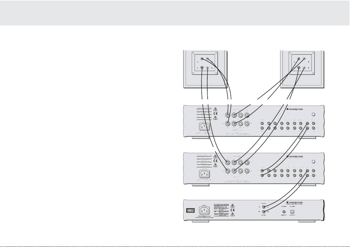
540A/640A Integrated amplifier
Bi-aamping
The azur amplifiers are equipped with PRE-OUT sockets. If your
loudspeakers have two sets of terminals then it is possible to bi-amp
your system using a further power amplifier. Bi-amping uses two
amplifiers to drive the bass and treble units in the loudspeakers
independently, resulting in even greater clarity coupled with improved
control and dynamics. An example of a bi-amp setup is illustrated in the
diagram adjacent.
Please note that if using a second azur amplifier as the slave amplifier,
any line input can be used to connect from the master’s Pre-Out.
Using SSpeaker BB connections
The Speaker B connections on the back of the amplifier allow a second
set of speakers to be used, which could be for another room.
9
Tape In
R
ec Out 1
R
ec Out
2
Tape In
R
ec Out
1
R
ec Out
2
M
ax Power
C
onsumptio
n
:
615
W
P
re-Out
Pre-Out
I
mpedance 4 - 8 ohms
Impedance 4 - 8 ohms
L
oudspeaker Terminals
Loudspeaker Terminals
Important
Important
P
lease ensure that loudspeaker terminals are fully tightened
Please ensure that loudspeaker terminals are fully tightened
Veuillez s'assurer que les bornes de l'enceinte sont entierement serrees
Veuillez s'assurer que les bornes de l'enceinte sont entierement serrees
I
mpedance 4 - 8 ohm
s
Impedance 4 - 8 ohms
R
ight
Right
L
eft
Left
R
ight
Right
Left
Left
L
eft
Left
B
B
A
A
Ri
g
ht
Right
Left
Left
Right
Right
B
B
A
A
AV / MD
AV / MD
DVD
DVD
Tuner / DA
B
Tuner / DAB
C
D
CD
Aux / Phon
o
Aux / Phono
P
re-Out
Pre-Out
AV
/
MD
AV / MD
DVD
DVD
Tuner / DAB
Tuner / DAB
C
D
CD
Aux / Phon
o
Aux / Phono
Righ
t
Right
Left
Left
R
ight
Right
L
eft
Left
Groun
d
Ground
w
ww.cambridge-audio.co.uk
www.cambridge-audio.co.uk
M
anufactured in an
Manufactured in an
I
SO900
2
ISO9002
approved facilit
y
approved facility
P
ower A
C
Power AC
D
esigned and Engineered in London, England
Designed and Engineered in London, England
R
isk of electric shock
Risk of electric shock
D
o not o
p
en
Do not open
Caut
i
on
Caution
Risque de choc electriqu
e
Risque de choc electrique
N
e
p
as ouvr
i
r
Ne pas ouvrir
A
v
is
Avis
Vorm offnen des gerates
Vorm offnen des gerates
N
etzstecker ziehen
Netzstecker ziehen
Achtun
g
Achtung
azur 6
4
0A Integrated Amplifie
r
azur 640A Integrated Amplifier
Power Rating:
Power Rating:
230V AC 50Hz
230V AC 50Hz
Ta
p
e In
Rec Out 1
R
ec Out
2
T
ape I
n
Rec Out 1
Rec Out 2
P
re-Out
Pre-Out
I
m
p
edance 4 - 8 ohms
Impedance 4 - 8 ohms
L
oudspeaker Terminals
Loudspeaker Terminals
Important
Important
P
lease ensure that loudspeaker terminals are fully tightened
Please ensure that loudspeaker terminals are fully tightened
Veuillez s'assurer que les bornes de l'enceinte sont entierement serrees
Veuillez s'assurer que les bornes de l'enceinte sont entierement serrees
I
m
p
edance 4 - 8 ohm
s
Impedance 4 - 8 ohms
Ri
g
h
t
Right
L
eft
Left
Ri
g
h
t
Right
Left
Left
L
eft
Left
B
B
A
A
Righ
t
Right
Left
Left
Right
Right
B
B
A
A
AV
/
MD
AV / MD
DVD
DVD
Tuner
/
DA
B
Tuner / DAB
C
D
CD
Aux
/
Phon
o
Aux / Phono
P
re-Out
Pre-Out
AV
/
MD
AV / MD
DVD
DVD
T
uner
/
DAB
Tuner / DAB
C
D
CD
A
ux
/
Ph
on
o
Aux / Phono
Righ
t
Right
Left
Left
R
ight
Right
L
eft
Left
Groun
d
Ground
w
ww.cambridge-audio.co.uk
www.cambridge-audio.co.uk
M
anufactured in an
Manufactured in an
I
SO900
2
ISO9002
approved facility
approved facility
P
ower A
C
Power AC
D
esigned and Engineered in London, England
Designed and Engineered in London, England
R
isk of electric shock
Risk of electric shock
D
o not open
Do not open
C
autio
n
Caution
Ris
q
ue de choc electri
q
u
e
Risque de choc electrique
Ne pas ouvrir
Ne pas ouvrir
A
vi
s
Avis
Vorm offnen des gerates
Vorm offnen des gerates
N
etzstec
k
er z
i
e
h
en
Netzstecker ziehen
Achtun
g
Achtung
azur 6
4
0A Inte
g
rated Amplifie
r
azur 640A Integrated Amplifier
Power Rating:
Power Rating:
230V AC 50Hz
230V AC 50Hz
M
ax Power
C
onsumptio
n
Max Power Consumption
:
:
615
W
615W
Treble Treble
Bass Bass
Slave aamplifier
- if using an integrated amplifier, volume must be set to full
Master aamplifier
CD player
Standby/On
Please note that care should be taken when selecting if two
loudspeakers are going to be used on each channel. If the combined
Switches the unit between Standby mode (indicated by dim power LED)
resistance measured on the speaker terminals is too low the amplifier
and On (indicated by bright power LED). Standby is a low power mode
may not switch out of standby mode until a suitable load resistance is
where the power consumption is less than 10 Watts. The unit should be
detected. For more information please see section on CAP5 protection
left in standby when not in use.
system.
Note - WWhen uusing ttwo ppairs oof sspeakers eeach ppair sshould bbe rrated aat
Headphone ssocket
least 66 oohms ((or hhigher). 44 oohm
sspeakers aare nnot rrecommended wwhen
Allows for the connection of headphones with a ¼" Jack plug connector.
using mmore tthan oone ppair.
When the headphones are connected the loudspeaker relay is released
switching off the output to the loudspeakers (Speakers A and B).
Direct
This control gives the audio signal a more direct path to the power
Speaker BB oon/off
amplifier stage of your amplifier, bypassing the tone control circuits for
Enables/disables the secondary set of speaker terminals on the back
the purest possible sound quality.
panel. This can be used for listening to an extra set of speakers in
another room.
10
azur 640A
Integrated Amplifier
Volume
TrebleBass
Balance
Protection
Standby / On
Speaker BPhones
Direct
Aux / Phono
CD
DVD
AV / MDTuner / DAB
Tape Mon
OPERATING INSTRUCTIONS

540A/640A Integrated amplifier
Bass aand ttreble ttone ccontrols
Input sselection ppush bbuttons
These controls allow subtle adjustments to the tonal balance of the
Push the appropriate input selection button to select the source
sound. In the central position these controls have no effect. These
component that you wish to listen to. The signal selected is also fed to
controls only modify the sound through your loudspeakers and the Pre-
the Tape Out sockets so that it may be recorded. The input should not
Out sockets (where featured), they do not affect the signals sent through
be changed whilst recording, although the recorded signal can be
the Tape Out connections. With a well produced CD and a good system
checked using the tape input Tape monitor.
the tone controls are unnecessary and can be switched out. If the
musical recording is of poor quality and/or the
Tape mmonitor sselection bbutton
loudspeakers/surroundings are lacking it may be necessary to adjust
the tone controls to compensate.
This control lets you listen to the output signal from a tape recorder or
signal processor connected to the amplifier's Tape monitor sockets.
When Tape monitor is selected, the source component chosen by the
Volume
input selection push buttons continues to be routed to the Tape Out
The Volume control increases/decreases the level of the sound from the
sockets for recording or processing.
outputs of the amplifier. This control affects the level of the Loudspeaker
output, the pre amp output and the headphone output. It does not affect
Remote ccontrol ooperation/features
the Tape Out Connections.
This Amplifier is supplied with a system remote control that operates
It is advisable to turn the Volume control fully anti-clockwise before
both this amplifier and the Cambridge Azur CD players. The functions
switching the amplifier on.
relevant to the amplifier are as follows:
Power -
Switches the amplifier between Standby mode and On mode.
Balance
Mute -
Mutes the audio (indicated by the input LED flashing).
This control allows you to adjust the relative output levels of the left and
right channels. In the central position the output from each channel is
Volume ++/-
- The volume buttons increase and decrease the Volume of
equal. This control only modifies the sound through your loudspeakers
the amplifier output.
and the Pre-Out sockets (where featured), it does not affect the signals
sent through the Tape Out connections.
Input sselect -
The five input select buttons and the Tape monitor select
button are used to change the input source.
11

CAP5 - FIVE WAY PROTECTION SYSTEM
Cambridge Audio has developed a proprietry protection system to
If the Loudspeaker impedance is low the temperature of the amplifier
ensure reliability and a long life to its amplifiers. This protection system
may rise faster as the amplifier is working harder. If the amplifier is
comprises of five main protection methods:
mounted in a cabinet or the ventilation slots are obstructed the over
temperature detection may activate/reactivate after a short listening
time.
Intelligent cclipping ddetection
CAP5 has the ability to detect when the amplifier starts to clip or
Short ccircuit ddetection
overdrive its output, which can damage Loudspeakers, the amplifier
power supply and most importantly degrade the sound. When CAP5
During power up from standby or during input channel selection CAP5
detects clipping the volume will be automatically nudged down until
performs a check on the Loudspeaker terminals to see if a short across
CAP5 detects an undistorted* output (*the volume is nudged down until
the terminals has been accidentally introduced. If the resistance
the distortion is less than 2% which listening tests have shown is
measured across the Loudspeaker terminals is too low the unit will stay
difficult to hear).
in Standby mode until the fault has been removed and Power up is re-
attempted.
It is possible to disable only this feature by holding down the Standby
button during power up (whilst plugging the unit into the mains power).
The unit will indicate this by flashing the protection LED for several
DC ddetection
seconds. Disabling the clipping detection is not advised as this feature
CAP5 offers Loudspeaker protection if the output of the amplifier goes
has been added to protect the amplifier.
to DC because of some internal fault. This is a rare fault although it
could just save those expensive Loudspeakers.
Over ttemperature ddetection
If the amplifier is switched out of standby when the input signal to the
CAP5 includes temperature detection which constantly monitors the
amplifier is too high (with the current volume setting) the CAP5 system
heat generated by the output transistors. When the monitored
will detect this and reduce the volume to a suitable level.
temperature reaches a high level (suitably within the limits of the output
devices) the amplifier will automatically switch into a fault mode
Overvoltage/overcurrent ddetection
(indicated by double flashing of the protection LED). The unit should
ideally be left for 15 minutes in this state to cool down adequately. If the
CAP5 offers V/I protection by constantly monitoring the output
unit has not fully cooled down then the temperature may reach the limit
transistors to keep them working inside their Safe Operating Area (SOA).
soon after the amplifier is powered up.
The SOA is a set of limits given by the output transistor manufacturer to
ensure reliability. Many amplifier designers include V/I limiting in the
12

540A/640A Integrated amplifier
signal path which can degrade the signal by compressing dynamics. The
CAP5 system operates outside the signal path and when triggered shuts
down the amp rather than limits the size of the signal passing through
the amp (signal compression). V/I protects the amplifier against short
circuits on the speaker terminals during use.
Indication
Fault/Remedy
Protection LED flashes for 4 seconds when unit attempts to come out of
CAP5 has detected that the resistance on the Loudspeaker terminals is
Standby mode.
too low. Check to see if there is a short circuit between the Loudspeaker
terminals.
Note: If the indication remains the same and multiple Loudspeakers are
being used on each Loudspeaker output then please remove a pair and
retry. If too many Loudspeakers are connected to any amplifier causing
the Load resistance to drop too low the amplifier will overheat. CAP5 will
detect this situation.
If the indication remains the same with only one set of loudspeakers
connected then there could possibly be a fault with one or both of the
loudspeakers.
Unit has switched off during operation. Protection LED constantly
ddoouubbllee
CAP5 has detected a user related fault, the internal temperature of the
ffllaasshheess..
output transistors has reached the over temperature limit. The unit is not
damaged although it should be left for 15 minutes to cool down before
being switched out of standby.
Unit has switched off during operation. Protection LED constantly
ffllaasshheess
CAP5 has detected a user related fault, there maybe a short circuit
oonn aanndd ooffff iinn bbuurrssttss ooff 44
.
between the loudspeaker terminals. Please check all Loudspeaker
connections before attempting to switch unit out of standby
Unit has switched off during operation. Protection LED is
oonn wwiitthh aa bbrriieeff
CAP5 has detected a fault which requires the unit to be serviced. DC has
ooffff ffllaasshh
.
been detected on the output of the amplifier which could damage the
speakers. The amplifier is now unusable. Please switch off and contact
dealer.
13

TROUBLESHOOTING
SPECIFICATIONS
There iis nno ppower
540A 640A
Ensure the AC power cord is connected securely.
Ensure the plug is fully inserted into the wall socket and is switched on.
Check fuse in the mains plug or adaptor
Power OOutput
75W (into 4Ω)
100W (into 4Ω)
50W (into 8Ω)
65W (into 8Ω)
There iis nno ssound
Make sure the unit is not in Standby mode
Max PPower
Check that source component is properly connected
Consumption
515W
615W
Check that 'TAPE MON' is not switched on (unless tape input is required)
Check that your speakers are properly connected
Standby PPower
If using Speaker B terminals check they are switched on
If channel LED is flashing turn mute off
Consumption
6W
6W
There iis nno ssound oon oone cchannel
THD (unweighted)
1kHz < 0.009%
1kHz < 0.005%
Ensure that balance control is in the correct position
Check speaker connections
20kHz < 0.09%
20kHz < 0.07%
Check interconnects
There iis aa lloud bbuzz oor hhum
Freq RResponse
(-33dB)
5Hz - 50kHz
4Hz - 80kHz
Check turntable or tone arm for ground and connection lead fault
Ensure no interconnects are loose or defective
S tto NN RRatio
(unweighted)
92dB
92dB
Ensure that your tape deck/turntable is not too close to the amplifier
Unable tto mmake oor pplay ttape rrecordings
Slew RRate
(into 88ΩΩ)
30V/uS
50V/uS
Check that TAPE MON and TAPE OUT have been connected correctly
There iis wweak bbass oor ddiffused sstereo iimaging
Dimensions
(HxWxD)
Ensure that speakers are not wired out of phase
mm
100 x 430 x 310
100 x 430 x 310
Will nnot sswitch oout oof sstandby - pprotection LLED flashing
inches
3.9 x 16.9 x 12.2
3.9 x 16.9 x 12.2
Please see section on CAP5 protection system
Weight
Protection LLED flashing
Please see section on CAP5 protection system (page 12)
kg
7
7
Lbs
15.4
15.4
14

540A/640A Integrated amplifier
LIMITED WARRANTY
Cambridge Audio warrants this product to be free from defects in
Cambridge Audio dealer, or authorised service agent which is authorised
materials and workmanship (subject to the terms set forth below).
to do Cambridge Audio warranty work. Any unauthorised repairs will void
Cambridge Audio will repair or replace (at Cambridge Audio's option) this
this Warranty. This Warranty does not cover products sold AS IS or WITH
product or any defective parts in this product. Warranty periods may vary
ALL FAULTS.
from country to country. If in doubt consult your dealer and ensure that
you retain proof of purchase.
REPAIRS OR REPLACEMENTS AS PROVIDED UNDER THIS WARRANTY
ARE THE EXCLUSIVE REMEDY OF THE CONSUMER. CAMBRIDGE AUDIO
To obtain warranty service, please contact the Cambridge Audio
SHALL NOT BE LIABLE FOR ANY INCIDENTAL OR CONSEQUENTIAL
authorised dealer from which you purchased this product. If your dealer
DAMAGES FOR BREACH OF ANY EXPRESS OR IMPLIED WARRANTY IN
is not equipped to perform the repair of your Cambridge Audio product,
THIS PRODUCT. EXCEPT TO THE EXTENT PROHIBITED BY LAW, THIS
it can be returned by your dealer to Cambridge Audio or an authorised
WARRANTY IS EXCLUSIVE AND IN LIEU OF ALL OTHER EXPRESS AND
Cambridge Audio service agent. You will need to ship this product in
IMPLIED WARRANTIES WHATSOEVER INCLUDING, BUT NOT LIMITED TO,
either its original packaging or packaging affording an equal degree of
THE WARRANTY OF MERCHANTABILITY AND FITNESS FOR A PRACTICAL
protection.
PURPOSE.
Proof of purchase in the form of a bill of sale or receipted invoice, which
Some countries and US states do not allow the exclusion or limitation of
is evidence that this product is within the warranty period, must be
incidental or consequential damages or implied warranties so the above
presented to obtain warranty service.
exclusions may not apply to you. This Warranty gives you specific legal
rights, and you may have other statutory rights, which vary from state to
This Warranty is invalid if (a) the factory-applied serial number has been
state or country to country.
altered or removed from this product or (b) this product was not
purchased from a Cambridge Audio authorised dealer. You may call
Cambridge Audio or your local country Cambridge Audio distributor to
confirm that you have an unaltered serial number and/or you purchased
from a Cambridge Audio authorised dealer.
This Warranty does not cover cosmetic damage or damage due to acts
of God, accident, misuse, abuse, negligence, commercial use, or
modification of, or to any part of, the product. This Warranty does not
cover damage due to improper operation, maintenance or installation,
or attempted repair by anyone other than Cambridge Audio or a
15

EINLEITUNG
Vielen DDank, ddass SSie ssich ffür ddie AAnschaffung eeines CCambridge AAudio-
Ringkern-Transformatoren, parallel geschaltete Speicherkondensatoren
Verstärkers aaus dder AAzur-SSerie e
entschieden hhaben. DDieses GGerät iist ddas
sowie Bypass-Kondensatoren garantieren jederzeit eine saubere,
Resultat uunserer bbis hheute aaufwendigsten FForschung uund EEntwicklung.
dynamische Stromversorgung. Dies wiederum ermöglicht ein
Wir wwünschen IIhnen mmit ddiesem EErgebnis llangjährige FFreude.
kraftvolles, dynamisches Klangbild voller natürlicher Details und Fülle.
Besondere Aufmerksamkeit wurde der Auswahl passiver Bauteile
gewidmet, welche insbesondere nach klanglichen Kriterien ausgewählt
Einige DDetails
wurden. Im Azur 640A kommen zudem spezielle Polypropylen-
Planung und Entwicklung jedes puristischen Hifi-Verstärker-Konzepts
Kondensatoren zum Einsatz, insbesondere an klanglich sensiblen
konzentriert sich im Wesentlichen auf zwei Baugruppen, die
Punkten im Signalweg.
Stromversorgung und eine möglichst effiziente Treiberstufe
Hifi-Puristen können das Klangregelnetzwerk des Azur 540A / 640A bei
(Vorverstärker) zur Ansteuerung der Leistungstransistoren, also der
Bedarf komplett überbrücken. Es wird somit vollständig aus dem
eigentlichen Endstufe. Dem Cambridge Audio Entwickler-Team ist es
Signalweg entfernt. Der Anschluß eines Kopfhörers ist ebenfalls
gelungen, in diesen beiden wichtigen Bereichen die bestmögliche
möglich. Er wird direkt aus der kraftvollen Endstufe gespeist.
Lösung zu finden, um technisch Machbares in einem bisher nicht
dagewesenen Preis-/Leistungsverhältnis zu realisieren. Die bewährten
Eine neu entwickelte innovative Schutzschaltung, das Cambridge Audio
Leistungstransistoren der Verstärker Azur 540A / 640A kamen schon in
CAP5 System , schützt die Verstärker Azur 540A / 640A vor einer
den äußerst erfolgreichen Vorgänger-Modellen zum Einsatz. Die
Vielzahl möglicherweise auftretenden Defekte oder Fehlbedienungen.
vorgeschalteten Verstärker-Stufen wurden jedoch komplett neu
Dies geschieht durch prozessorgesteuerte Überwachung, ohne
entwickelt.
zusätzliche aktive Bauteile im Signalweg.
Auf Grund des überaus durchdachten Layouts, sorgfältig plazierter
All unser Wissen und langjährige Erfahrung haben wir in die neue Azur
Bauteile und kurzer Signalwege ergibt sich eine extrem hohe Stabilität
Generation einfließen lassen. Mit viel Liebe zum Detail entstanden Hifi-
der Verstärkerschaltung. Kompensationsschaltungen können somit auf
Verstärker, die klanglich wegen ihrer hohen Auflösung und Dynamik
ein Minimum reduziert werden. Verzerrungen können drastisch
überzeugen. Sie begeistern durch eine lebhafte, fließende Darbietung
reduziert werden. Dynamik und auch die Bandbreite von 80 kHz (!) -
jeder Art von Musik. Diese Verstärker beziehen den Hörer ins
wünschenswert für die hochauflösenden Formate wie DVD-Audio und
Klanggeschehen voll ein!
SACD - werden den Anforderungen neuer Medien gerecht.
Um das musikalische Potential dieses Gerätes voll ausschöpfen zu
Der Klang und die Performance eines Hifi-Verstärkers werden sehr oft
können, empfehlen wir sehr, bei der Auswahl der übrigen Komponenten
durch eine begrenzte Dynamik der Stromversorgung limitiert. Kräftige
Ihrer Stereoanlage auf ebenso hohe Qualität zu achten. Natürlich raten
16
