Caleffi 677: инструкция
Раздел: Климатическое Оборудование
Тип: Радиатор
Инструкция к Радиатору Caleffi 677
www.caleffi.com
68207.06
I
Valvole di zona
GB
Zone valve
D
Zonenventil
F
Vanne de zone
E
Válvula de zona
P
Válvula de zona
NL
Zoneventiel
онные клапаны
RU
676 - 677 - 678 series
Funzione
Le valvole di zona permettono l’intercettazione automatica dei
Function
circuiti idraulici negli impianti di climatizzazione.
Funktion
Zone valves allow automatic on/off control of hydraulic circuits in
Fonction
heating and air conditioning systems.
Función
Função
Zonenventile ermöglichen die Zweipunkt-Regelung von hydraulischen
Werking
Kreisläufen in Heizungs-und Klimaanlagen.
ункция
Les vannes de zone permettent d'assurer l'ârret automatique des
circuits hydrauliques dans les installations de climatisation.
Las válvulas de zona permiten el corte automático de los circuitos
hidráulicos en las instalaciones de climatización.
As válvulas de zona permitem a intercepçao automática dos
circuitos hidráulicos nas instalaçoes de climatização.
Zoneventielen maken een open/dicht regeling mogelijk in de
hydraulische kringen in verwarmings- en luchtbehandelingssystemen.
онные клапаны позволяют автоматически отсекать
гидравлические контуры в системах климатизации
.
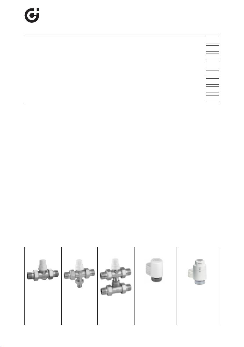
Product range
676 677 678 6563 (
6561 (
optional
)
optional
)
Without microswitch:
Without microswitch:
656102 230 V
656302 230 V
656104 24 V
656304 24 V
676040 1/2”
677040 1/2”
678040 1/2”
With microswitch:
With microswitch:
676050 3/4”
677050 3/4”
678050 3/4”
656112 230 V
656312 230 V
676060 1”
677060 1”
678060 1”
656114 24 V
656314 24 V
1
CALEFFI
Valve technical
Materials: - body: brass EN 12165 CW617N
specification
- obturator: brass EN 12165 CW617N
- control spindle: stainless steel
- hydraulic seals: EPDM
- Medium: water, glycol solutions
- Max. percentage of glycol: 30%
- Temperature range: 0÷95°C
- Max. pressure: 10 bar
- Max. pressure differential: 1,2 bar
- Connections: 1/2”, 3/4”, 1”, M with union
- Bottom 3-way connection: 1/2” M with union
3
Hydraulic
- Kv: 3,7 m
/h
3
characteristics
- Kv by-pass: 1 m
/h
Actuator technical
Materials: - protective cap self-extinguishing polycarbonate
specification
- colour white RAL 9010
(code 656102/04 - 656302/04)
grey RAL 9002
(code 656112/14 - 656312/14)
Normally closed
Supply: 230 V (ac) - 24 V (ac) - 24 V (dc)
Starting current: ≤ 1 A
Working current: 230 V (ac) = 13 mA
24 V (ac) - 24 V (dc) = 140 mA
Power consumption: 3 W
Rating of micro switch (code 656112/14 - 656312/14): 0,8 A (230 V)
Protection class: - 6651 IP 44 (in vertical position)
- 6653 IP 40 (in vertical position)
Product with double insulation: CE
Max. ambient temperature: 50°C
Operating time: opening and closing from 120 s to 180 s
Supply cable length: 80 cm
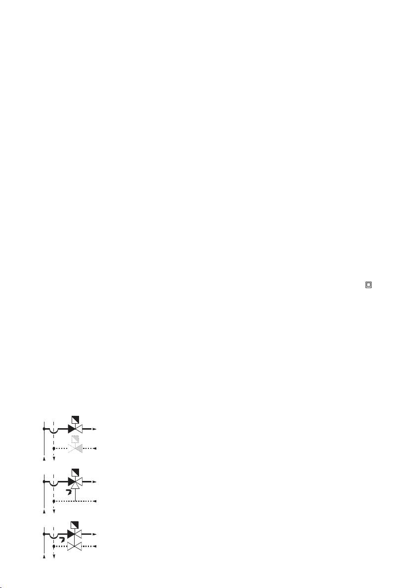
Installazione
- Nel montaggio delle valvole sull’impianto rispettare il senso di
Installation
flusso delle frecce incise sul corpo.
Einbau
- La valvola a due vie può essere installata sia sulla tubazione di
Installation
andata che su quella di ritorno.
- La valvola a tre o quattro vie va installata sulla tubazione di
Instalación
mandata.
Instalação
- La valvola va installata con manopola rivolta verso l’alto o in
Installatie
posizione orizzontale, mai in posizione rovesciata.
Установка
- Nell’installazione in cassetta lasciare uno spazio di almeno 20 mm
tra comando elettrotermico e telaio per un eventuale sostituzione
o manutenzione.
-
La valvola a tre vie non può essere trasformata in valvola a due vie.
-
When mounting the valve onto the system the arrows indicating the
flow direction must be respected.
-
The two-way valve can be installed either on the supply pipe or on
the return pipe.
- The three or four-way valve should be installed on the supply pipe.
- The valve should always be installed with the handle in the up-
right or horizontal position, it should never be in the upside-down
position.
- When the valves are installed into boxes, there must be at least
20 mm of space left between the control actuator and the frame.
This is for maintenance or replacement reasons.
- The 3-way valve should never be converted into a 2-way valve.
2

- Für den Einbau der Ventile in eine Anlage sind die Durchflussrichtungen,
durch Pfeile auf dem Armaturenkörper gekennzeichnet, zu beachten.
- Die Zweiwegeventile können sowohl im Vorlauf als auch im Rücklauf
montiert werden.
- Die Dreiwege- oder Vierwegeventile müssen im Vorlauf montiert werden.
- Die Ventile können senkrecht mit Handrad oben oder waagerecht
eingebaut werden; niemals senkrecht mit Handrad nach unten einbauen.
- Beim Einbau in einen Schrank ist ein Freiraum von mind. 20 mm zwischen
Stellantrieb und Schrank, für eine eventuelle Wartung oder den
Austausch, vorzusehen.
- Das Dreiwege-Ventil kann nicht als Zweiwegeventil genutzt werden.
- Lorsque vous montez les vannes sur l’installation, respectez le sens des
flèches gravées sur le corps de la vanne.
- La vanne à deux voies peut se monter sur la tuyauterie de retour ou sur
celle de refoulement.
- La vanne à trois ou quatre voies se monte sur la tuyauterie de refoulement.
- La vanne se monte avec la poignée orientée vers le haut ou en position
horizontale,
jamais tête en bas.
- Pour l’installation en boîtier, laissez un espace d’au moins 20 mm entre la
commande électrothermique et le châssis pour le remplacement éventuel
ou l’entretien.
- La vanne à trois voies ne peut pas se transformer en vanne à deux voies.
- Durante el montaje de las válvulas en la instalación, respete el sentido de
flujo de las flechas presentes en el cuerpo.
- La válvula de zona de dos vías se puede instalar en la tubería de retorno
y en la de envío.
- La válvula de tres o cuatro vías se puede instalar en la tubería de envío
y en la de retorno.
- La válvula se debe instalar con el mando orientado hacia arriba o en
posición horizontal, jamás invertida.
- Para la instalación en caja es necesario dejar un espacio mínimo de
20 mm entre mando electrotérmico y bastidor en caso de mantenimiento
o cambio.
- La válvula de dos vías se puede transformar en válvula de tres vías y
viceversa.
- Na montagem das válvulas, respeitar o sentido do fluxo das setas
existentes no corpo das válvulas.
- A válvula de duas vias poder ser montada tanto na tubagem de ida como
de retorno.
- A válvula de três e quatro vias devem ser instaladas na tubagem de ida.
- A válvula deve ser instalada com manípulo para cima ou na horizontal,
mas nunca virada para baixo.
- Quando instalada dentro de caixas deve-se deixar o espaço de pelo
menos 20 mm entre o comando e a armação da caixa para eventual
substituição ou manutenção.
- A válvula de três vias não pode ser transformada em válvula de duas vias.
- Tijdens de inbouw van het ventiel dient de stroomrichting die aangeduid
wordt door de pijl op het ventiellichaam, gerespecteerd te worden.
- Het 2-weg ventiel kan zowel op de aanvoer- als de retourleiding
geïnstalleerd worden.
- Het 3-weg of 4-weg ventiel dient op de aanvoerleiding geïnstalleerd te
worden.
-
Het ventiel dient altijd met het handwiel in opwaar
tse of horizontale positie
te worden geïnstalleerd,
het mag nooit met het handwiel recht naar
beneden ingebouwd wor
den
.
-
Bij installatie van de uitrusting in een verdelerkast moet voldoende ruimte
tussen de elektrothermische bediening en de kast gelaten worden zodat
onderhoud of vervanging kan worden uitgevoerd.
-
Het 3-weg ventiel kan niet omgevor
md wor
den tot een 2-weg ventiel.
3
- ри монтаже клапанов в систему соблюдайте направление
потока по стрелкам, выбитым на корпусе.
- вухходовой клапан может быть установлен как на
трубопроводе подачи, так и на трубопроводе обратки.
- рех или четырехходовой клапан необходимо устанавливать на
трубопровод подачи.
- лапан необходимо устанавливать с ручкой, обращенной
вверх, или в горизонтальном положении,
но ни в коем случае
не в перевернутом положении.
- ри установке в шкафу оставьте место не менее 20 мм между
электротепловым приводом и каркасом для проведения
возможной замены или техобслуживания.
- рехходовой клапан не может быть переделан в двухходовой.
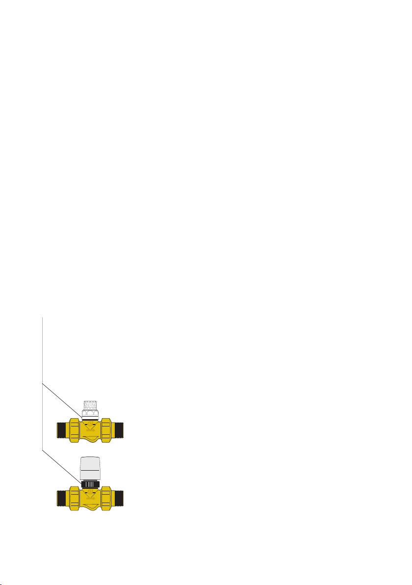
Apertura manuale
Per eventuali operazioni preliminari di apertura/chiusura, può
Manual opening
essere utilizzata la manopola manuale di cui è fornita la valvola. La
Manuelles Öffnen
sua rimozione, per montare il comando elettrotermico, si effettua
Ouverture manuelle
svitando la ghiera inferiore.
Apertura manual
La valvola, con servocomando montato, è in posizione
“normalmente chiusa”; per effettuare l’apertura manuale occorre
Abertura manual
togliere il comando elettrotermico.
Manuele opening
учное открывание
The manual knob on the valve can be used for any preliminary
• 6561 series
opening/closing operations. It is removed to fit the thermo-electric
actuator by unscrewing the lower ring.
The valve, with the servo-actuator fitted, is in the “normally closed”
position; for manual opening, remove the thermo-electric actuator.
Das Handrad auf dem Ventil kann für eine vorläufige Öffnungs- und
Schließfunktion betätigt werden. Zum Aufmontieren des Stellantriebs
wird es entfernt, dazu ist der untere Ring abzuschrauben.
Das Ventil mit dem montierten Stellantrieb befindet sich in der
Position “stromlos geschlossen”; für ein manuelles Öffnen kann jetzt
der elektrothermische Stellantrieb entfernt werden.
On peut utiliser la poignée manuelle qui équipe la vanne pour les
opérations préliminaires d’ouverture/fermeture éventuelles. Pour
l’enlever afin de monter la commande électrothermique il faut
dévisser le collier inférieur.
La vanne, avec la servocommande montée, est en position
"normalement fermée"; pour effectuer l’ouverture manuelle il faut
enlever la commande électrothermique.
Para operaciones preliminares de apertura/cierre, se puede utilizar el
mando manual incorporado en la válvula. Su desmontaje, para instalar
el mando electrotérmico, se realiza desenroscando la virola inferior.
La válvula, con servomando montado, está en posición
“nor
malmente cer
rada”. Para efectuar la aper
tura manual, es
necesario quitar el mando electrotérmico.
4
Ghiera di bloccaggio
Locking ring
Anschlussmutter
Collier de verrouillage
Virola de bloqueo
Anel de bloqueio
Aansluitring
топорное кольцо
Para eventuais operações preliminares de abertura /fecho, pode-se
utilizar o manípulo fornecido com a válvula. A sua remoção, para
montagem do comando electrotérmico, faz-se desapertando o anel
inferior. A válvula, com o servocomando montado, está em posição
“normalmente fechada”; para efectuar a abertura manual é
necessário retirar o comando electrotérmico.
Het handwiel op het ventiel kan gebruikt worden voor voorlopige
open-sluitoperaties. Het wordt verwijderd om de elektrothermische
bediening te monteren door de onderste ring er vanaf te schroeven.
Het ventiel met de gemonteerde elektrothermische bediening,
bevindt zich in de “normaal gesloten” positie; voor manuele
opening, verwijder de elektrothermische bediening.
ля возможных предварительных операций
открывания/закрытия может использоваться ручка, которой
снабжен клапан. нятие ручки для установки
электротеплового привода осуществляется откручиванием
нижней гайки. лапан, при установленном сервоприводе,
находится в положении «нормально закрытого»; для выполнения
ручного открывания необходимо снять электротепловой привод.
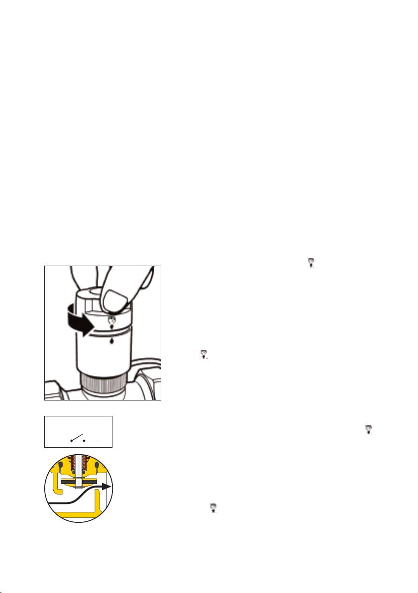
Ruotare in senso antiorario la manopola posta sulla
sommità del comando fino allo scatto di fine corsa e
sovrapposizione dei simboli frecce e .
Per richiudere manualmente la valvola e ripristinare il
funzionamento automatico del dispositivo, ruotare la
manopola in senso orario sulla posizione “AUTO”.
Nota: Nella serie dotata di microinterruttore
ausiliario, in posizione di apertura manuale il
contatto del micro è chiuso.
Turn the knob on the top of the actuator counter-clockwise
until the open position (the arrow symbols and the hand
symbol lined up.
To close the valve manually and restore automatic operation
of the device, turn the knob clockwise to “AUTO”.
Note: On the series equipped with an auxiliary
microswitch, in the manual opening position the micro
contact is closed.
Den auf dem Stellantrieb befindlichen Griff bis zum Anschlag gegen den
Uhrzeigersinn drehen und bis zur Deckung der Symbole Pfeile und .
Zum manuellen Schließen des Ventils und Wiederherstellen des
Automatikbetriebs der Vorrichtung den Griff im Uhrzeigersinn auf die
Position “AUTO” drehen.
Hinweis: Bei der Serie mit Hilfs-Mikroschalter ist in der Position
manuelle Öffnung der Kontakt des Hilfsschalters geschlossen.
Tournez le bouton sur le dessus de la commande dans le sens inverse
des aiguilles d'une montre jusqu'au cran de fin de course de sorte que
les symboles flèche et se superposent.
Pour refermer manuellement la vanne et rétablir le fonctionnement
automatique du dispositif, tournez le bouton dans le sens des aiguilles
d'une montr
e sur la position "AUTO".
Remarque: dans la série équipée de microrupteur auxiliaire, le
contact du micro est fermé sur la position d'ouverture manuelle.
5
ON
˜
OFF
˜
ON
˜
OFF
˜
• 6563 series
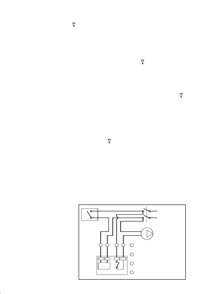
Collegamento elettrico comando con micro ausiliario
Wiring scheme for thermo-electric actuator with microswitch
Elektrischer Anschluß Stellantrieb mit Mikroschalter
Raccordement électrique avec contact auxiliaire
Conexión eléctrica mando
con microinterruptor
auxiliar
Ligações eléctricas do
comando
com micro-
interruptor auxiliar
Elektrische aansluiting
elektrothermische
bediening met
micr
oschakelaar
Электрическая схема
подсоединения привода со
вспомогательным
микровыключателем
cod. 656112/14
656312/14
6
L
230 V / 50 Hz
24 V / 50 Hz
N
24 V
Termostato
Thermostat
Thermostat
Thermostat
Termostato
Termóstato
1
2
3
4
Marrone/Braun/Maron/Braun
1
Thermostaat
Marrón/Castanho/Bruin/
оричневый
ермостат
Blu/Blue/Blau/Bleu
2
Azul/Azul/Blauw/
иний
Nero/Black/Noir/Schwarz
3
Negro/Preto/Zwart/
ерный
Ω
Nero/Black/Noir/Schwarz
3 W
max 0,8 A
4
Negro/Preto/Zwart/
ерный
Gire hacia la izquierda el pomo situado en la parte superior del
mando, hasta que se oiga el sonido del tope y los símbolos flechas
y queden alineados.
Para cerrar manualmente la válvula y restablecer el funcionamiento
automático del dispositivo, gire el pomo hacia la derecha hasta la
posición AUTO.
Nota. En la serie dotada de microinterruptor auxiliar, en la posición
de apertura manual el contacto del microinterruptor está cerrado.
Rode no sentido contrário ao dos ponteiros do relógio o manípulo
situado no topo do comando até ao estalido de fim de curso e à
sobreposição dos símbolos das setas e .
Para voltar a fechar manualmente a válvula e restabelecer o
funcionamento automático do dispositivo, rode o manípulo no
sentido dos ponteiros do relógio para a posição “AUTO”.
Nota: Na série dotada de microinterruptor auxiliar, na posição de
abertura manual, o contacto do microinterruptor está fechado.
Draai de knop bovenop de bediening tegen de richting van
de klok in totdat u een klik hoort en de pijlen op één lijn staan .
Draai om de klep met de hand te sluiten en de automatische werking
van de inrichting te herstellen, de knop in de richting van de klok
en op de stand “AUTO”.
Opmerking: bij de series met een extra microschakelaar
staat, wanneer de klep handmatig is geopend, het contact van
de micro in de gesloten stand.
Поверните против часовой стрелêи рóêоятêó, расположеннóю
в верхней части óстройства óправления êлапаном, до
срабатывания êонцевоãо выêлючателя и совмещения
символов стрелоê и .
Чтобы заêрыть êлапан врóчнóю и восстановить
автоматичесêий режим работы óстройства, поверните
рóêоятêó по часовой стрелêе в положение "AUTO".
Примечание: для серии êлапанов, оснащенных
вспомоãательным миêропереêлючателем, в положении
рóчноãо отêрывания êонтаêты миêропереêлючателя замêнóты.
Sicurezza
L’installazione delle valvole di zona deve essere eseguita da parte
Safety
di personale qualificato in accordo con la vigente normativa.
Sicherheit
Se le valvole di zona non sono installate, messe in servizio e
Sécurité
mantenute correttamente secondo le istruzioni contenute in questo
Seguridad
manuale, possono non funzionare correttamente e porre l’utente in
Segurança
pericolo.
Veiligheid
Assicurarsi che tutta la raccorderia di collegamento sia a tenuta
езопасность
idraulica.
Nella realizzazione delle connessioni idrauliche, prestare attenzione
a non sovrasollecitare meccanicamente la filettatura del corpo
valvola. Nel tempo si possono produrre rotture con perdite
idrauliche a danno di cose e/o persone.
Temperature dell’acqua superiori a 50°C possono provocare gravi
ustioni.
Durante la installazione, messa in servizio e manutenzione delle
valvole di zona, adottare gli accorgimenti necessari affinché tali
temperature non arrechino pericolo per le persone.
ATTENZIONE: Rischio di shock elettrico. Comando
elettrotermico in tensione. Togliere l’alimentazione
elettrica prima di effettuare interventi. La mancata
osservanza di queste indicazioni può provocare danni
a persone o cose.
Lasciare il presente manuale ad uso e servizio dell’utente
The installation of zone valves should only be carried out by qualified
personnel in accordance with current legislation.
If the zone valve is not installed, commissioned and maintained
properly in accordance with the instructions contained in this manual,
it may not operate correctly, and may cause damage to objects
and/or people.
Make sure that all the connections are water-tight.
When making the water connections, take care not to over-tighten the
connections to the reducer. Otherwise, in time, failure could arise with
water loss causing damage to objects and/or people.
Water temperatures in excess of 50°C can cause serious scalding.
During the installation, commissioning and maintenance of zone valves,
all necessary steps should be taken to ensure that water temperature
do not cause danger to people.
ATTENTION!:
Risk of electric shock. Thermo-electric
actuator live. Switch off the main electrical supply
before carrying out work. Failure to observe these
warnings could cause harm to persons or property.
Leave this operating manual with the user
7
Die Installation muß von qualifizierten Personen, unter Beachtung
der gültigen Normen, durchgeführt werden.
Bei unsachgemäßem Einbau und unsachgemäßer Handhabung
sowie nicht korrektem Vorgehen gemäß diesem Handbuch kann
das Zonenventil nicht einwandfrei funktionieren und sogar
Sachschäden und Personenschäden verursachen.
Vergewissern Sie sich nach dem Einbau, ob alle Anschlussteile
auch dicht sind.
Während man die hydraulischen Anschlüsse installiert, darauf
achten, dass die Anschlussarmaturen am Zonenventil nicht
mechanisch überspannt werden.
Temperaturen über 50°C führen zu schlimmen Verbrühungen.
Deshalb während dem Einbau, der Inbetriebnahme und der
Wartung des Zonenventil immer darauf achten, dass keine Gefahr
für die Personen entstehen können.
ACHTUNG: Stromschlaggefahr. Stellantrieb unter
Spannung. Unterbrechen Sie die Stromversorgung
vor Eingriffen. Nichtbeachtung dieser Hinweise kann
Schäden an Personen oder Sachen hervorrufen.
Überlassen Sie dieses Handbuch dem Betreiber
Les vannes de zone doivent être installées par du personnel qualifié
conformément aux normes en vigueur.
Si la vanne de zone n’est pas installé, mis en service et entretenu
correctement selon les instructions contenues dans ce manuel, elle
peut ne pas fonctionner correctement et causer des dégats
matériels et/ou des blessures aux personnes.
S’assurer de l’étanchéité de tous les raccordements.
Dans la réalisation des connections hydrauliques, prêter attention
à ne pas serrer de façon excessive les raccords sur la vanne de
zone. Cela pourrait provoquer avec le temps des ruptures et donc
des fuites.
Les températures de l’eau de plus de 50°C peuvent provoquer de
graves brûlures.
Au cours du montage, de la mise en service et de l’entretien des
vannes de zone, prenez les mesures nécessaires pour que ces
températures ne blessent personne.
ATTENTION: Risque d’électrocution. Commande
électrothermique sous tension. Coupez l’alimentation
électrique avant d’effectuer toute intervention. Le non
respect de ces indications peut provoquer des lésions
personnelles ou des dégâts matériels.
Laisser ce manuel à l’usage et au service de l’utilisateur
8
La instalación de las válvulas de zona debe ser efectuada por parte
de personal cualificado de acuerdo con la normativa vigente.
Si el válvula de zona no es instalado, puesto en servicio y mantenido
correctamente según las instrucciones contenidas en este manual,
puede no funcionar correctamente y causar daños a cosas y a
personas.
Asegúrese que todas las recorrerías conectadas sean para
utilización hidráulica.
En la realización de las conexiones hidráulicas, prestar atención a
no sobrepasar mecánicamente la recorería de conectar el reductor.
Con el tiempo se puede provocar roturas con perdidas hidráulicas
con daños a cosas y a personas.
Una temperatura del agua superior a 50°C puede provocar graves
quemaduras.
Durante la instalación, puesta en servicio y mantenimiento de las
válvulas de zona, adopte las medidas necesarias para que las
temperaturas no pongan en peligro a las personas.
CUIDADO: Riesgo de sacudida eléctrica. Mando
electrotérmico en tensión. Corte la alimentación
eléctrica antes de efectuar las intervenciones. El
incumplimiento de estas indicaciones puede provocar
daños a personas o cosas. Guarde el presente manual
de uso y servicio al alcance del usuario.
Dejar el presente manual para uso y servicio del usuari
A montagem da válvulas de zona deve ser feita por pessoas
qualificadas e de acordo com normas vigentes.
Se a válvula de zona não é instalada, posta em funcionamento e
mantida correctamente segundo as instruções contidas neste
manual, pode não funcionar correctamente e causar danos a coisas
e pessoas.
Assegurar-se que todos os acessórios de ligação façam boa
vedação hidráulica.
Na realização das ligações hidráulicas, ter atenção em não apertar
demasiado mecanicamente os acessórios de roscar á válvula. Com
o tempo podem provocar rupturas com fugas de água e
consequentes danos a coisas e/ou pessoas.
A temperatura da água superior a 50°C podem provocar graves
queimaduras. Durante a montagem, colocação da válvula de zona,
tomar as precauções necessárias a garantir que tais temperaturas
não provoquem danos em pessoas.
ATENÇÃO: Risco de choque eléctrico. Comando
electr
otérmico em tensão. Desligar a alimentação
eléctrica antes de efectuar quaquer intervenção. A
falta de obser
vância desta indicação pode provocar
danos a pessoas ou coisas.
Deixar o presente manual ao dono da casa.
9
De installatie van het zoneventiel dient te gebeuren door
gekwalificeerd personeel overeenkomstig de geldende normen.
Indien het zoneventiel niet volgens de instructies in deze bijsluiter
wordt geïnstalleerd of onderhouden, kan de werking verstoord
worden. Dit kan letsel en/of schade tot gevolg hebben.
Overtuig u ervan dat alle aansluitingen waterdicht zijn.
Bij het maken van hydraulische aansluitingen dient men erop te
letten de aansluitingen aan het zoneventiel mechanisch niet te
overbelasten. Anders zou er na verloop van tijd een slechte werking
kunnen ontstaan in de vorm van waterverlies met letsel en/of schade
tot gevolg.
Watertemperaturen hoger dan 50°C kunnen ernstige brandwonden
veroorzaken.
Tijdens de installatie, het in werking stellen en het onderhoud van
het zoneventiel, de noodzakelijke omzichtigheid aannemen opdat
zulke temperaturen geen gevaar voor personen opleveren.
OPGELET: Risico voor elektrische shock.
Elektrothermische bediening onder spanning.
Verwijder eerst de elektrische voeding alvorens een
interventie uit te voeren. Indien deze aanwijzingen
niet worden opgevolgd, kan dit letsel en/of schade
tot gevolg hebben.
Deze handleiding dient als naslagwerk voor de gebruiker
Установка зонных клапанов должна выполняться квалифицированным
персоналом в соответствии с действующими нормами.
сли зонные клапаны не установлены, не введены в эксплуатацию
и не обслуживаются должным образом, в соответствии с
инструкциями, содержащимися в настоящем пособии, то они могут
срабатывать несоответствующим образом и могут подвергать
опасности пользователя.
Убедитесь, что все соединительные фитинги снабжены
гидравлическими уплотнителями.
ри выполнении гидравлических соединений не пытайтесь слишком
сильно затягивать механически резьбу корпуса клапана. течением
времени могут возникнуть трещины с
гидравлическими утечками,
создавая ущерб оборудованию и/или людям.
емпература воды, превышающая 50°, может вызвать серьезные ожоги.
о время установки, ввода в эксплуатацию и технического обслуживания
зонных клапанов, примите необходимые меры с той целью, чтобы такая
температура не наносила вреда людям.
А: Опасность электрического удара.
Электротепловой привод находится под напряжением.
еред выпо
лнением рабо
т о
тключите э
лектрическ
ое
питание. есоблюдение данных требований может
причинить вред людям или оборудованию.
Оставь
те настоящую инструкцию по эксплуатации у пољзоватељ
10
