Caleffi 6453: инструкция
Раздел: Климатическое Оборудование
Тип: Радиатор
Инструкция к Радиатору Caleffi 6453
ITALIANO ENGLISH FRANÇAIS DEUTSCH
6452
42
DN 20 / 1/2”
230 V
6452
52
DN 20 / 3/4”
230 V
6452
62
DN 25 / 1”
230 V
6452
72
DN 25 / 1 1/4” 230 V
6452
44
DN 20 / 1/2”
24 V
6452
54
DN 20 / 3/4”
24 V
6452
64
DN 25 / 1”
24 V
6452
74
DN 25 / 1 1/4” 24 V
I EN FR DE
ISTRUZIONI PER L’INSTALLAZIONE,
LA MESSA IN SERVIZIO E LA
MANUTENZIONE
Vi ringraziamo per averci preferito nella
scelta di questo prodotto
Ulteriori dettagli tecnici su questo
dispositivo sono disponibili sul sito
www.caleffi.com
VALVOLE DI ZONA A SFERA
MOTORIZZATE PER IMPIANTI
DI CONDIZIONAMENTO
Generalità
Queste serie di valvole di zona a sfera motorizzate sono
dotate di marchi CE secondo le direttive 2006/95/CE e
2004/108/CE.
Avvertenze
Le seguenti istruzioni devono essere lette e comprese prima
dell’installazione e della manutenzione del prodotto. Il
simbolo
significa:
ATTENZIONE! UNA MANCANZA NEL SEGUIRE QUESTE
ISTRUZIONI POTREBBE ORIGINARE PERICOLO!
Sicurezza
É obbligatorio rispettare le istruzioni per la sicurezza
riportate sul documento specifico in confezione.
LASCIARE IL PRESENTE MANUALE AD USO
E SERVIZIO DELL’UTENTE
SMALTIRE IN CONFORMITÀ ALLA NORMATIVA VIGENTE
Funzione
Le valvole di zona permettono l’intercettazione automatica dei
circuiti idraulici negli impianti di climatizzazione.
Caratteristiche tecniche
Materiali
Corpo:
ottone UNI EN 12165 CW617N
Sfera:
ottone UNI EN 12165 CW617N, cromata
Tenuta sfera:
PTFE con O-Ring in EPDM
Tenuta asta comando:
doppio O-Ring in EPDM
Tenuta bocchettoni:
O-Ring in EPDM
Prestazioni
Fluidi di impiego:
acqua, soluzioni glicolate
Max percentuale di glicole:
50%
Pressione massima d’esercizio:
10 bar
Pressione differenziale massima:
10 bar
Attacchi:
1/2”, 3/4”, 1”, 1 1/4”, M a bocchettone
Attacco inferiore 3 vie:
3/4” F
Condizioni ambientali (valvola + comando)
Campo di temperatura fluido:
-10÷110°C
Temperatura ambiente:
Funzionamento: -10÷55°C EN 60721-3-3 Cl. 3K4, max. umidità 95%
Trasporto: -30÷70°C EN 60721-3-2 Cl. 2K3, max. umidità 95%
Stoccaggio: -20÷70°C EN 60721-3-1 Cl. 1K2, max. umidità 95%
Caratteristiche tecniche comando
Motore sincrono
Alimentazione:
230 V (ac)
24 V (ac)
Assorbimento:
6 VA
Portata contatti microinterruttore ausiliario:
6 (2) A (230 V)
Grado di protezione:
IP 65
Tempo di manovra:
50 s (rotazione 90°)
Lunghezza cavo di alimentazione:
0,8 m
Coppia di spunto dinamico:
9 N·m
Caratteristiche tecniche coibentazione
Materiale:
PE-X espanso a celle chiuse
Spessore:
15 mm
Densità: - parte interna:
30 kg/m
3
- parte esterna:
80 kg/m
3
Conducibiltà termica (DIN 52612): - a 0°C:
0,038 W/(m·K)
- a 40°C
0,045 W/(m·K)
Coefficiente resistenza diffusione vapore (DIN 52615):
>1.300
Campo di temperatura:
0÷100°C
Reazione al fuoco (DIN 4102):
classe B2
Caratteristiche idrauliche
(fig. A)
Installazione
(fig. B - C - D)
Installazione con coibentazione
(fig. E - F - G - H - I - L - M)
1 Nel montaggio delle valvole sull’impianto rispettare il senso di
flusso delle frecce incise sul corpo.
2 La valvola a due vie può essere installata sia sulla tubazione di
andata che su quella di ritorno.
3 La valvola a tre vie va installata sulla tubazione di mandata.
4 La valvola ed il servocomando vengono forniti in posizione
“APERTO”
Apertura/chiusura manuale
(fig. N - O - P)
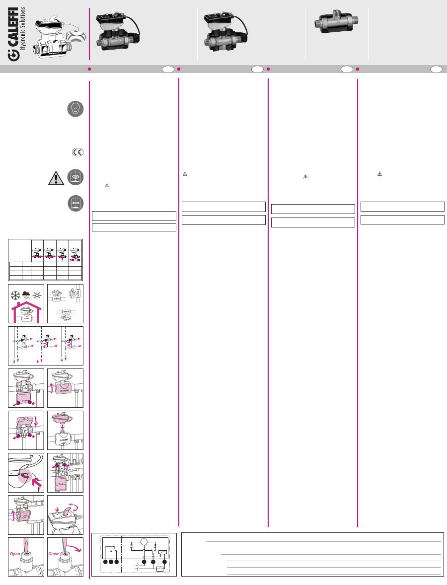
Schema elettrico
(fig. Q)
Schema interno con valvola in posizione di
chiusura
1 = Verde
2 = Bianco
3 = Rosso
4 = Blu
5 = Marrone
6 = Nero
Microinterruttore ausiliario
Il microinterruttore ausiliario è azionato dal movimento di
apertura del servocomando. Il microinterruttore ausiliario si
chiude per un valore medio di apertura del servocomando
dell’95%.
INSTRUCTIONS FOR INSTALLATION,
COMMISSIONING AND
MAINTENANCE
Thank you for choosing our product.
Further technical details relating to this
device
are
available
at
www.caleffi.com
MOTORISED BALL ZONE VALVES
FOR AIR CONDITIONING SYSTEMS
General
These series of motorised ball zone valves carry the
CE marks in accordance with Directives 2006/95/EC and
2004/108/EC.
Warnings
The following instructions must be read and understood
before installing and maintaining the product. The symbol
means:
CAUTION! FAILURE TO FOLLOW THESE INSTRUCTIONS
COULD RESULT IN A SAFETY HAZARD!
Safety
The safety instructions provided in the specific document
supplied MUST be observed.
LEAVE THIS MANUAL AS A REFERENCE GUIDE
FOR THE USER
DISPOSE OF THE PRODUCT IN COMPLIANCE WITH
CURRENT LEGISLATION
Function
The zone valves can be used to automatically shut off hydraulic
circuits in heating and cooling systems.
Technical specifications
Materials
Body:
brass UNI EN 12165 CW617N
Ball:
brass UNI EN 12165 CW617N, chrome plated
Ball seal:
PTFE with EPDM O-Ring
Stem seal:
EPDM double O-Ring
Union seal:
EPDM O-Ring
Performance
Medium:
water, glycol solutions
Max. percentage of glycol:
50%
Max. working pressure:
10 bar
Max. differential pressure:
10 bar
Connections:
1/2”, 3/4”, 1”, 1 1/4”, M with union
Bottom 3-way connection:
3/4” F
Ambient conditions (valve + control)
Medium working temperature range:
-10
–
110°C
Ambient temperature:
Operation: -10
–
55°C EN 60721-3-3 Cl. 3K4, max. humidity 95%
Transportation:-30
–
70°C EN 60721-3-2 Cl. 2K3, max. humidity 95%
Storage:
-20
–
50°C EN 60721-3-1 Cl. 1K2, max. humidity 95%
Actuator technical specification
Synchronous motor
Electrical supply:
230 V (ac)
24 V (ac)
Power consumption:
6 VA
Auxiliary microswitch contact rating:
6 (2) A (230 V)
Protection class:
IP 65
Operating time:
50 s (rotation 90°)
Max. ambient temperature:
55°C
Supply cable length:
0,8 m
Dynamic starting torque:
9 N·m
Insulation technical specifications
Material:
closed cell expanded PE-X
Thickness:
15 mm
Density:
- internal part:
80 kg/m3
- external part:
50 kg/m3
Thermal conductivity (DIN 52612): - at 0°C
0,038 W/(m·K)
- at 40°C
0,045 W/(m·K)
Coefficient of resistance to the diffusion of water vapour
(DIN 52615):
>1.300
Working temperature range:
0-100°C
Reaction to fire (DIN 4102):
class B2
Hydraulic characteristics
(fig. A)
Installation
(fig. B - C - D)
Installation with insulation
(fig. E - F - G - H - I - L - M)
1 When mounting the valves onto the system respect the flow
direction indicated by the arrows engraved on the body.
2 The two-way valve can be installed on both the supply piping as
well as the return piping.
3 The three-way valve must be installed on the supply piping.
4 The valve and actuator are supplied in “OPEN” position.
Manual opening/closing
(fig. N - O - P)
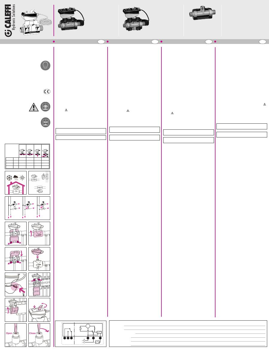
Wiring diagram
Internal diagram with valve in closed position
(fig. Q)
1 = Green
2 = White
3 = Red
4 = Blue
5 = Brown
6 = Black
Auxiliary microswitch
The auxiliary microswitch is activated by the opening movement
of the actuator. The auxiliary microswitch shuts off for an average
actuator opening value of 95%.
CONSIGNES POUR L’INSTALLATION,
LA MISE EN SERVICE ET L’ENTRETIEN
Merci d’avoir choisi ce produit.
Pour de plus amples informations sur
ce dispositif, veuillez consulter le site
www.caleffi.com
VANNES DE ZONE À SPHÈRE
À BILLE MOTORISÉES, POUR
INSTALLATIONS DE
CLIMATISATION
Généralités
Ces séries de vannes de zone à sphère motorisées
portent le label CE conformément aux directives
2006/95/CE et 2004/108/CE.
Avertissements
S’assurer d’avoir lu et compris les instructions suivantes
avant de procéder à l’installation et à l’entretien du
dispositif. Le symbole
signifie :
ATTENTION ! LE NON-RESPECT DE CES CONSIGNES
PEUT ENTRAÎNER UNE MISE EN DANGER !
Sécurité
Respecter impérativement les consignes de sécurité
citées sur le document qui accompagne le dispositif.
LAISSER CE MANUEL
AU SERVICE DE L’UTILISATEUR
METTRE AU REBUT CONFORMÉMENT AUX NORMES
EN VIGUEUR
Fonction
Les vannes de zone permettent d'arrêter automatiquement
les débits des fluides dans les installations de climatisation.
Caractéristiques techniques
Matériaux
Corps :
laiton UNI EN 12165 CW617N
Bille :
laiton UNI EN 12165 CW614N, chromée
Sièges sphère :
PTFE avec O’Ring en EPDM
Joint axe de commande :
double O’Ring en EPDM
Joint raccords unions :
O-Ring en EPDM
Performance
Fluide admissible : eau, solutions glycolées
Pourcentage maxi de glycol :
50%
Pression maxi d'exercice :
10 bar
Pression différentielle maximale :
10 bar
Raccordements :
Raccords unions 1/2”, 3/4”, 1”, 1 1/4”, M
Raccord inférieur 3ème voie :
3/4” F
Conditions ambiantes (vanne + tête)
Plage de température du fluide :
-10÷110°C
Température ambiante :
Fonctionnement
:
-10÷55°C EN 60721-3-3 Cl. 3K4, humidité maxi 95%
Transport : -30÷70°C EN 60721-3-2 Cl. 2K3, humidité maxi 95%
Stockage : -20÷70°C EN 60721-3-1 Cl. 1K2, humidité maxi 95%
Caractéristiques techniques du moteur
Moteur synchrone
Alimentation :
230 V (ca)
24 V (ca)
Puissance absorbée :
6 VA
Pouvoir de coupure contact auxiliaire :
6 (2) A (230 V)
Indice de protection :
IP 65
Temps de manœuvre :
50 s (rotation 90°)
Longueur du câble d'alimentation :
0,8 m
Couple de démarrage dynamique :
9 N·m
Caractéristiques techniques isolation
Matériau :
PE-X expansé à cellules fermées
Épaisseur :
15 mm
Densité :
- partie intérieure :
30 kg/m3
- partie extérieure :
80 kg/m3
Conductibilité thermique (DIN 52612) : - à 0°C : 0,038 W/(m·K)
- à 40°C 0,045 W/(m·K)
Coefficient de résistance à la déperdition de vapeur
(DIN 52615) :
>1 300
Plage de température :
0÷100°C
Réaction au feu (DIN 4102) :
classe B2
Caractéristiques hydrauliques
(fig. A)
Installation
(fig. B - C - D)
Installation avec isolation
(fig. E - F - G - H - I - L - M)
1 Lorsque vous montez les vannes sur l’installation, respectez le
sens des flèches gravées sur le corps de la vanne.
2 La vanne deux voies peut se monter sur la tuyauterie de départ
ou sur celle du retour.
3 La vanne trois voies se monte sur la tuyauterie de départ .
4 La vanne et le servomoteur sont fournis en position
« OUVERTE »
Ouverture/fermeture manuelle
(fig. N - O - P)
Schéma électrique :
Schéma interne avec vanne en position de
fermeture (fig. Q)
1 = Vert
2 = Blanc
3 = Rouge
4 = Bleu
5 = Marron
6 = Noir
Contact auxiliaire
Le contact auxiliaire est actionné par le mouvement d'ouverture
du servomoteur. Le contact auxiliaire se ferme à une valeur
moyenne d'ouverture du servomoteur de 95%.
INSTALLATIONS-,
INBETRIEBNAHME- UND
WARTUNGSANWEISUNGEN
Wir bedanken uns, dass Sie sich für
unser Produkt entschieden haben.
Weitere technische Details zu diesem
Gerät finden Sie unter www.caleffi.com
MOTOR-ZONENKUGELVENTILE
FÜR KLIMAANLAGEN
Allgemeines
Diese Serie von Motor-Zonenkugelventilen verfügt über die
CE-Kennzeichnung gemäß den Richtlinien 2006/95/EG und
2004/108/EG.
Hinweis
Die folgenden Anweisungen müssen vor Installation und
Wartung des Gerätes gelesen und verstanden worden sein.
Das Symbol
bedeutet:
ACHTUNG! EINE MISSACHTUNG DIESER ANWEISUNGEN
KANN GEFAHRENSITUATIONEN VERURSACHEN!
Sicherheit
Die in der beigelegten Dokumentation enthaltenen
Sicherheitsanweisungen müssen beachtet werden.
DIESE ANLEITUNG IST DEM
BENUTZER AUSZUHÄNDIGEN
DEN GELTENDEN VORSCHRIFTEN ENTSPRECHEND
ENTSORGEN
Funktion
Zonenventile zur automatischen Regelung der Durchflussmenge
von Klimageräten.
Technische Eigenschaften
Materialien
Gehäuse:
Messing EN 12165 CW617N
Kugel:
Messing UNI EN 12165 CW617N, verchromt
Kugeldichtung:
PTFE mit O-Ring aus EPDM
Steuerspindeldichtung: doppelter O-Ring aus EPDM
Verschraubungsdichtung:
O-Ring aus EPDM
Leistungen
Betriebsmedien:
Wasser, Glykollösungen
Maximaler Glykolgehalt:
50%
Max. Betriebsdruck:
10 bar
Maximaler Differenzdruck:
10 bar
Anschlüsse:
1/2”, 3/4”, 1”, 1 1/4”, AG mit Überwurf
Unterer 3-Wege-Anschluss:
3/4” IG
Arbeitsbereich - Ventil und Antrieb
Temperaturbereich des Mediums:
-10÷110°C
Umgebungstemperatur:
Betrieb: -10÷55°C EN 60721-3-3 Kl. 3K4, max. Feuchtigkeit 95%
Transport:-30÷70°C EN 60721-3-2 Kl. 2K3, max. Feuchtigkeit 95%
Lagerung:-20÷70°C EN 60721-3-1 Kl. 1K2, max. Feuchtigkeit 95%
Technische Eigenschaften Wärmedämmschale
Synchronmotor
Betriebsspannung:
230 V (ac)
24 V (ac)
Leistungsaufnahme:
6 VA
Stromaufnahme des Hilfsschalters:
6 (2) A (230 V)
Schutzart:
IP 65
Schaltzeit:
50 s (90°-Drehung)
Kabellänge:
0,8 m
Dynamisches Anlaufmoment:
9 N·m
Technische Dämmeigenschaften
Material:
Geschlossenzelliger PE-X-Schaum
Dicke:
15 mm
Dichte:
- Innenteil:
30 kg/m3
- Außenteil:
80 kg/m3
Wärmeleitfähigkeit (DIN 52612):
- bei 0°C:
0,038 W/(m·K)
- bei 40°C
0,045 W/(m·K)
Dampfdiffusions-Widerstandszahl (DIN 52615):
>1.300
Temperaturbereich:
0÷100°C
Feuerwiderstand (DIN 4102):
Klasse B2
Hydraulische Eigenschaften
(Abb. A)
Installation
(Abb. B - C - D)
Installation mit Dämmung
(Abb. E - F - G - H - I - L - M)
1 Einbau gemäß Kennzeichnung der Fliessrichtung am
Armaturenkörper.
2 Die Zweiwegeventile können sowohl im Vorlauf als auch im
Rücklauf montiert werden.
3 Die Dreiwege-ventile müssen im Vorlauf montiert werden.
4 Das Ventil und der Stellantrieb werden in „OFFENER“ Stellung
geliefert
Manuelles Öffnen/Schließen
(Abb. N - O - P)
Schaltplan:
Innenschema mit Ventil in Schließstellung
(Abb. Q)
1 = Grün
2 = Weiß
3 = Rot
4 = Blau
5 = Braun
6 = Schwarz
Hilfsschalter
Der Hilfsschalter schließt bei einem mittleren Öffnungswert des
Stellantriebs von 95%.
68
45
2
6453
42
DN 20 / 1/2”
230 V
6453
52
DN 20 / 3/4”
230 V
6453
62
DN 25 / 1”
230 V
6453
72
DN 25 / 1 1/4” 230 V
6453
44
DN 20 / 1/2”
24 V
6453
54
DN 20 / 3/4”
24 V
6453
64
DN 25 / 1”
24 V
6453
74
DN 25 / 1 1/4” 24 V
6459
40
DN 20 / 1/2”
6459
50
DN 20 / 3/4”
6459
60
DN 25 / 1”
6459
70
DN 25 / 1 1/4”
© Copyright 2011 Caleffi
www.caleffi.com
E
I
L
M
N
O
P
B
G
F
C
H
A
DN 20 1/2”
17,00 14,10
2,45
2,20
DN 20 3/4”
17,27 14,43
2,50
2,25
DN 25
1”
36,58 33,52
3,60
3,25
DN 25 11/4”
39,50 36,00
3,80
3,40
6452
6453
6453
6453 +
6459
Kv
(m
3
/h)
D
NOTE:
NOTES:
REMARQUES :
ANMERKUNGEN:
M
Max 6(2) A
(230 V ˜)
MC2
MC1
N
L
MICRO
AUX
1
2
3
4
5
6
2
3
0
V
(a
c
)
2
4
V
(a
c
)
Q
PORTUGUÊS NEDERLANDS RUSSO PT NL RU
INSTRUÇÕES PARA A INSTALAÇÃO,
COLOCAÇÃO EM SERVIÇO E
MANUTENÇÃO
Agradecemos
a
preferência
na
selecção deste produto.
Dados técnicos adicionais sobre este
dispositivo encontram-se disponíveis
no site www.caleffi.com.
VÁLVULAS DE ZONA DE ESFERA
MOTORIZADAS PARA
INSTALAÇÕES DE CLIMATIZAÇÃO
Generalidades
Esta série de válvulas de zona de esfera motorizadas
possui a marca CE segundo as das directivas 2006/95/CE
e 2004/108/CE.
Advertências
As instruções que se seguem devem ser lidas e
compreendidas antes da instalação e da manutenção do
produto. O símbolo
significa:
ATENÇÃO! O INCUMPRIMENTO DESTAS INSTRUÇÕES
PODERÁ ORIGINAR PERIGO!
Segurança
É obrigatório respeitar as instruções de segurança
indicadas no documento específico contido na embalagem.
DEIXAR O PRESENTE MANUAL
À DISPOSIÇÃO DO UTILIZADOR
ELIMINAR EM CONFORMIDADE
COM AS NORMAS EM VIGOR
Função
As válvulas de zona permitem a intercepção automática dos
circuitos hidráulicos na instalações de climatização.
Características técnicas
Materiais
Corpo:
latão UNI EN 12165 CW617N
Esfera:
latão UNI EN 12165 CW617N, cromada
Vedação da esfera:
PTFE com O-Ring em EPDM
Vedação haste de comando:
duplo O-Ring em EPDM
Vedação dos casquilhos:
O-Ring em EPDM
Desempenho
Fluidos de utilização: água, soluções com glicol
Percentagem máx. de glicol:
50%
Pressão máxima de exercício:
10 bar
Pressão diferencial máxima:
10 bar
Ligações:
1/2”, 3/4”, 1”, 1 1/4”, M com casquilho
Ligação inferior 3 vias:
3/4” F
Condições ambientais (válvula + comando)
Campo de temperatura fluido:
-10÷110°C
Temperatura ambiente:
Funcionamento:
-10÷55°C EN 60721-3-3 Cl. 3K4,
humidade máx. 95%
Transporte:
-30÷70°C EN 60721-3-2 Cl. 2K3,
humidade máx. 95%
Armazenamento:
-20÷70°C EN 60721-3-1 Cl. 1K2,
humidade máx. 95%
Características técnicas comando
Motor síncrono
Alimentação:
230 V (ac)
24 V (ac)
Consumo:
6 VA
Corrente contactos micro-interruptor auxiliar:
6 (2) A (230 V)
Grau de protecção:
IP 65
Tempo de manobra:
50 s (rotação 90°)
Comprimento do cabo de alimentação:
0,8 m
Binário de arranque dinâmico:
9 N·m
Características técnicas isolamento
Material:
PE-X
expandido
com
células fechadas
Espessura:
15 mm
Densidade:
- parte interna:
30 kg/m3
- parte externa:
80 kg/m3
Condutibilidade térmica (DIN 52612): - a 0°C:
0,038 W/(m·K)
- a 40°C
0,045 W/(m·K)
Coeficiente de resistência difusão do vapor (DIN 52615): >1.300
Campo de temperatura:
0÷100°C
Reacção ao fogo (DIN 4102):
classe B2
Características hidráulicas
(fig. A)
Instalação
(fig. B - C - D)
Instalação com isolamento
(fig. E - F - G - H - I - L - M)
1 Na montagem das válvulas na instalação, respeitar o sentido do
fluxo das setas existentes no corpo das válvulas.
2 A válvula de duas vias poder ser montada tanto na tubagem de
ida como na de retorno.
3 A válvula de três vias deve ser instalada na tubagem de ida.
4 A válvula e o servocomando são fornecidos na posição
“ABERTO”.
Abertura/fecho manual
(fig. N - O - P)
Esquema eléctrico:
Esquema interno com válvula na posição de
fecho (fig. Q)
1 = Verde
2 = Branco
3 = Vermelho
4 = Azul
5 = Castanho 6 = Preto
Micro-interruptor auxiliar
O micro-interruptor auxiliar é accionado pelo movimento de
abertura do servocomando. O micro-interruptor auxiliar fecha-se
no caso de um valor médio de abertura do servocomando de 95%.
AANWIJZINGEN VOOR INSTALLATIE,
INBEDRIJFSTELLING EN
ONDERHOUD
We bedanken U voor de keuze van een
van onze producten.
Nadere technische details omtrent dit
systeem vindt U op onze site
www.caleffi.com
GEMOTORISEERDE
ZONEVENTIELEN MET
KOGELAFSLUITER VOOR
KLIMAATREGELINGSINSTALLATIES
Algemeen
Deze
serie
gemotoriseerde
zoneventielen
met
kogelafsluiter is voorzien van het CE keurmerk in
overeenstemming met de richtlijnen 2006/95/EG en
2004/108/EG.
Waarschuwingen
De navolgende aanwijzingen aandachtig doorlezen alvorens
het product te installeren en onderhoud te verrichten. Het
symbool
betekent:
LET OP! NIET NAVOLGEN VAN DEZE AANWIJZINGEN
KAN GEVAARLIJK ZIJN!
Veiligheid
Het is verplicht de veiligheidsvoorschriften op te volgen die
vermeld staan op het specifieke document in de verpakking.
DE GEBRUIKER DIENT ALS NASLAGWERK VOOR DE
GEBRUIKER
HET PRODUCT VERWIJDEREN IN OVEREENSTEMMING
MET DE GELDENDE WETGEVING
Functie
Deze zoneventielen kunnen toegepast worden om automatisch
hydraulische circuits af te sluiten in klimaatregelingsinstallaties.
Technische gegevens
Materialen
Lichaam:
messing EN 12165 CW617N
Kogel:
messing EN 12165 CW617N. Verchroomd
Kogelafdichting
PTFE met O-ring in EPDM
Dichting regelstang:
dubbele O-ring in EPDM
Dichting wartels:
O-ring in EPDM
Prestaties
Vloeistof:
water, glycoloplossingen
Max. glycolpercentage:
50%
Max. werkingsdruk:
10 bar
Maximaal drukverschil:
10 bar
Aansluitingen:
1/2”, 3/4”, 1”, 1 1/4”, M met wartel
Onderste driewegaansluiting:
3/4” F
Omgevingscondities (ventiel + bediening)
Temperatuurbereik vloeistof:
-10 tot 110°C
Omgevingstemperatuur:
Werking: -10 tot 55°C EN 60721-3-3 Cl. 3K4, max. vochtigheid 95%
Transport:-30 tot 70°C EN 60721-3-2 Cl. 2K3, max. vochtigheid 95%
Opslag:-20 tot 70°C EN 60721-3-1 Cl. 1K2, max. vochtigheid 95%
Technische gegevens aandrijving
Synchroonmotor
Voeding:
230 V (ac)
24 V (ac)
Opgenomen vermogen:
6 VA
Capaciteit extra microschakelaar:
6 (2) A (230 V)
Beschermingsgraad:
IP 65
Schakeltijd:
50 s (rotatie 90°)
Kabel:
0,8 m
Dynamisch koppel:
9 N
Technische gegevens isolatie
Materiaal:
geëxpandeerd PE-X met gesloten cellenstructuur
Dikte:
15 mm
Dichtheid:
- binnenzijde:
30 kg/m3
- buitenzijde:
80 kg/m3
Thermische geleidbaarheid (DIN 52612): - bij 0°C: 0,038 W/(m·K)
- bij 40°C0,045 W/(m·K)
Dampweerstandscoëfficiënt (DIN 52615):
>1.300
Temperatuurbereik:
0÷100°C
Brandweerstand (DIN 4102):
klasse B2
Hydraulische gegevens
(fig. A)
Installatie
(fig. B - C - D)
Installatie met isolatie
(fig. E - F - G - H - I - L - M)
1 Tijdens de inbouw van het ventiel dient de stroomrichting die
aangeduid wordt door de pijl op het ventiellichaam,
gerespecteerd te worden.
2 Het 2-weg ventiel kan zowel op de aanvoer- als de retourleiding
geïnstalleerd worden.
3 Het 3-weg ventiel dient op de aanvoerleiding geïnstalleerd te
worden.
4 Het ventiel en de servomotor worden in de “OPEN” stand
geleverd.
Handmatig openen/sluiten
(fig. N - O - P)
Schakelschema:
Intern schema met ventiel in gesloten stand
(fig. Q)
1 = Groen
2 = Wit
3 = Rood
4 = Blauw
5 = Bruin
6 = Zwart
Extra microschakelaar
De extra microschakelaar wordt ingeschakeld door de
openingsbeweging
van
de
servomotor.
De
extra
microschakelaar sluit zich bij een gemiddelde openingswaarde
van de servomotor van 95%.
ESPAÑOL ES
INSTRUCCIONES DE INSTALACIÓN,
PUESTA EN MARCHA Y
MANTENIMIENTO
Gracias por escoger un producto de
nuestra marca.
Encontrará más información sobre
este
dispositivo
en
la
página
www.caleffi.com.
VÁLVULAS DE ZONA DE ESFERA
MOTORIZADAS PARA SISTEMAS
DE AIRE ACONDICIONADO
Generalidades
Las válvulas de zona de esfera motorizadas de esta serie
llevan el marcado CE de acuerdo con las directivas
2006/95/CE y 2004/108/CE.
Advertencias
Estas instrucciones deben leerse y comprenderse antes de
realizar la instalación y el mantenimiento del producto.
El símbolo
significa:
¡ATENCIÓN!
EL
INCUMPLIMIENTO
DE
ESTAS
INSTRUCCIONES PUEDE SER PELIGROSO.
Seguridad
Es obligatorio respetar las instrucciones de seguridad
indicadas en el documento específico que se entrega con
el producto.
ENTREGAR ESTE MANUAL
AL USUARIO
DESECHAR SEGÚN LA NORMATIVA LOCAL
Función
Las válvulas de zona cortan automáticamente el flujo de agua en
las instalaciones de climatización.
Características técnicas
Materiales
Cuerpo:
latón EN 12165 CW617N
Esfera:
latón EN 12165 CW614N, cromada
Sello de la esfera:
PTFE con junta tórica de EPDM
Sello del eje:
dos juntas tóricas de EPDM
Sello de los racores:
juntas tóricas de EPDM
Prestaciones
Fluido utilizable:
agua o soluciones de glicol
Porcentaje máximo de glicol:
50 %
Presión máxima de servicio:
10 bar
Presión diferencial máxima:
10 bar
Conexiones:
1/2", 3/4", 1" y 1 1/4", M con enlace
Conexión inferior 3 vías:
3/4" H
Condiciones ambientales (válvula y mando)
Campo de temperatura del fluido:
-10÷110 °C
Temperatura ambiente:
Funcionamiento: -10÷55 °C EN 60721-3-3 Cl. 3K4, hum. máx. 95
%
Transporte: -30÷70 °C EN 60721-3-2 Cl. 2K3, hum. máx. 95 %
Almacenamiento:-20÷70 °C EN 60721-3-1 Cl. 1K2, hum. máx. 95 %
Características técnicas del mando
Motor síncrono
Alimentación eléctrica:
230 V (ac)
24 V (ac)
Potencia absorbida:
6 VA
Capacidad contactos microinterruptor auxiliar:
6 (2) A (230 V)
Grado de protección:
IP 65
Tiempo de maniobra:
50 s (rotación 90°)
Longitud del cable de alimentación:
0,8 m
Par de arranque dinámico:
9 N·m
Características técnicas del aislamiento
Material:
PE-X reticulado de células cerradas
Espesor:
15 mm
Densidad:
- parte interior:
30 kg/m3
- parte exterior:
80 kg/m3
Conductividad térmica (DIN 52612): - a 0 °C:
0,038 W/(m·K)
- a 40 °C: 0,045 W/(m·K)
Coeficiente resistencia difusión del vapor (DIN 52615):
> 1300
Campo de temperatura:
0÷100 °C
Reacción al fuego (DIN 4102):
clase B2
Características hidráulicas
(fig. A)
Instalación
(fig. B - C - D)
Instalación con aislamiento
(fig. E - F - G - H - I - L - M)
1 Durante el montaje de las válvulas en la instalación, respete el
sentido de flujo de las flechas presentes en el cuerpo.
2 La válvula de zona de dos vías se puede instalar en la tubería de
retorno y en la de envío.
3 La válvula de tres vías se puede instalar en la tubería de envío
y en la de retorno.
4 La válvula y el servomando se suministran en posición de
“ABIERTO”.
Apertura/cierre manual
(fig. N - O - P)
Esquema eléctrico:
Esquema interno con válvula en posición de
cierre (fig. Q)
1 = Verde
2 = Blanco
3 = Rojo
4 = Azul
5 = Marrón
6 = Negro
Microinterruptor auxiliar
El microinterruptor auxiliar se acciona con el movimiento de
apertura del servomando. El microinterruptor auxiliar se cierra
cuando el servomando se abre aproximadamente al 95 %.
NOTAS:
NOTAS:
OPMERKINGEN:
ПРИМЕЧАНИЯ:
© Copyright 2011 Caleffi
www.caleffi.com
E
I
L
M
N
O
P
B
G
F
C
H
D
M
Max 6(2) A
(230 V ˜)
MC2
MC1
N
L
MICRO
AUX
1
2
3
4
5
6
2
3
0
V
(a
c
)
2
4
V
(a
c
)
P
ИНСТРУКЦИИ ПО УСТАНОВКЕ,
ПУСКУ В ЭКСПЛУАТАЦИЮ И
ТЕХОБСЛУЖИВАНИЮ
Благодарим Вас за выбор нашего
изделия.
За
дополнительной
технической
информацией по данному устройству
обращайтесь
к
Интернет-сайту
www.caleffi.com.
ШАРОВЫЕ ЗОННЫЕ КЛАПАНЫ С
ЭЛЕКТРОПРИВОДОМ ДЛЯ СИСТЕМ
КОНДИЦИОНИРОВАНИЯ ВОЗДУХА
Общие сведения
Эти шаровые зонные клапаны с электроприводом имеют
маркировку CE в соответствии с директивами 2006/95/CE и
2004/108/CE.
Предупреждения
Данные инструкции должны быть прочитаны и усвоены до
начала монтажа и техобслуживания изделия. Символ
означает:
ВНИМАНИЕ! НЕСОБЛЮДЕНИЕ ДАННЫХ ИНСТРУКЦИЙ МОЖЕТ
ПРИВЕСТИ К СОЗДАНИЮ ОПАСНЫХ СИТУАЦИЙ!
Безопасность
Обязательно соблюдайте инструкции по безопасности,
приведенные в специальном документе, входящем в
упаковку.
ДАННЫЕ ИНСТРУКЦИИ ДОЛЖНЫ НАХОДИТЬСЯ
В РАСПОРЯЖЕНИИ ПОЛЬЗОВАТЕЛЯ
УТИЛИЗАЦИЯ ДОЛЖНА ПРОВОДИТЬСЯ СОГЛАСНО
ДЕЙСТВУЮЩИМ НОРМАТИВАМ
Функциональное назначение
Зонные клапаны позволяют автоматически отключать
гидравлические контуры в системах климатизации
.
Технические характеристики
Материалы
Корпус:
латунь UNI EN 12165 CW617N
Шар:
латунь UNI EN 12165 CW617N, хромированная
Уплотнение шара:
тефлон (PTFE) с уплотнительным
кольцом из каучука EPDM
Уплотнение штока:
двойное уплотнительное кольцо
из каучука EPDM
Уплотнение патрубков: уплотнительное кольцо из каучука EPDM
Эксплуатационные характеристики
Рабочая среда:
вода, этиленгликолевые растворы
Максимальное процентное содержание этиленгликоля: 50%
Максимальное рабочее давление:
10 бар
Максимальное дифференциальное давление:
10 бар
Соединения: патрубки с наружной резьбой 1/2”, 3/4”, 1”, 1 1/4”
Нижний тройник:
3/4” с внутренней резьбой
Условия окружающей среды (клапан + привод)
Диапазон температуры жидкости:
-10÷110°C
Температура окружающей среды:
Функционирование:
-10÷55°C EN 60721-3-3 Cl. 3K4,
макс. влажность 95%
Транспортировка:
-30÷70°C EN 60721-3-2 Cl. 2K3,
макс. влажность 95%
Хранение:
-20÷70°C EN 60721-3-1 Cl. 1K2,
макс. влажность 95%
Технические характеристики привода
Синхронный двигатель
Электропитание:
230 В (переменное напряжение)
24 В (переменное напряжение)
Потребляемая мощность:
6 ВА
Ёмкость контактов вспомогательного
микропереключателя:
6 (2) A (230 В)
Класс защиты:
IP 65
Время срабатывания:
50 с (поворот на 90°)
Длина кабеля питания:
0,8 м
Динамический пусковой момент:
9Нм
Технические характеристики изоляции
Материал:
Сшитый полиэтилен PE-X с закрытыми ячейками
Толщина:
15 мм
Плотность:
- внутренняя часть:
30 кг/м3
- наружная часть:
80 кг/м3
Теплопроводность (DIN 52612):
- при 0°C:
0,038 Вт/(м·K)
- при 40°C
0,045 Вт/(м·K)
Коэффициент сопротивления диффузии водяного пара
(DIN 52615):
>1.300
Диапазон температур:
0÷100°C
Огнестойкость (DIN 4102):
класс B2
Гидравлические характеристики
(рис. A)
Монтаж
(рис. B - C - D)
Монтаж с изоляцией
(рис. E - F - G - H - I - L - M)
1. При установке клапанов в систему необходимо соблюдать
направление потока, указанное стрелками на корпусе.
2. Двухходовой клапан может устанавливаться как в напорной,
так и в возвратной линии.
3. Трехходовой клапан подлежит установке в напорной линии.
4 Клапан и сервопривод поставляются в положении “ОТКРЫТ”.
Ручное открывание/закрывание
(рис. N - O - P)
Электрическая схема:
Внутренняя схема при клапане в закрытом положении
(рис. Q)
1 = зеленый
2 = белый
3 = красный
4 = синий
5 = коричневый
6 = черный
Вспомогательный микровыключатель
Вспомогательный микровыключатель приводится в действие
за счет движения (открытия) сервопривода. Контакты
вспомогательного микропереключателя замыкаются при
среднем значении открытия сервопривода, равном 95%.
6452
42
DN 20 / 1/2”
230 V
6452
52
DN 20 / 3/4”
230 V
6452
62
DN 25 / 1”
230 V
6452
72
DN 25 / 1 1/4” 230 V
6452
44
DN 20 / 1/2”
24 V
6452
54
DN 20 / 3/4”
24 V
6452
64
DN 25 / 1”
24 V
6452
74
DN 25 / 1 1/4” 24 V
6453
42
DN 20 / 1/2”
230 V
6453
52
DN 20 / 3/4”
230 V
6453
62
DN 25 / 1”
230 V
6453
72
DN 25 / 1 1/4” 230 V
6453
44
DN 20 / 1/2”
24 V
6453
54
DN 20 / 3/4”
24 V
6453
64
DN 25 / 1”
24 V
6453
74
DN 25 / 1 1/4” 24 V
6459
40
DN 20 / 1/2”
6459
50
DN 20 / 3/4”
6459
60
DN 25 / 1”
6459
70
DN 25 / 1 1/4”
A
DN 20 1/2”
17,00 14,10
2,45
2,20
DN 20 3/4”
17,27 14,43
2,50
2,25
DN 25
1”
36,58 33,52
3,60
3,25
DN 25 11/4”
39,50 36,00
3,80
3,40
6452
6453
6453
6453 +
6459
Kv
(m
3
/h)
