Bosch GSS Professional 230 AE: инструкция
Раздел: Электроинструменты
Тип:
Инструкция к Bosch GSS Professional 230 AE
Robert Bosch GmbH
Power Tools Division
70745 Leinfelden-Echterdingen
Germany
www.bosch-pt.com
1 619 929 J37
(2012.01) O / 159
UNI
GSS
Professional
230 A | 230 AE | 280 A | 280 AE
de
Originalbetriebsanleitung
en
Original instructions
fr
Notice originale
es
Manual original
pt
Manual original
it
Istruzioni originali
nl
Oorspronkelijke
gebruiksaanwijzing
da
Original brugsanvisning
sv
Bruksanvisning i original
no
Original driftsinstruks
fi
Alkuperäiset ohjeet
el
Ðñùôüôõðï ïäçãéþí ÷ñÞóçò
tr
Orijinal işletme talimat
pl
Instrukcja oryginalna
cs
Původní návod k používání
sk
Pôvodný návod na použitie
hu
Eredeti használati utasítás
ru
Îðèãèíàëüíîå ðóêîâîäñòâî ïî
ýêñïëóàòàöèè
uk
Îðèã³íàëüíà ³íñòðóêö³ÿ ç
åêñïëóàòàö³¿
ro
Instrucţiuni originale
bg
Îðèãèíàëíà èíñòðóêöèÿ
sr
Originalno uputstvo za rad
sl
Izvirna navodila
hr
Originalne upute za rad
et
Algupärane kasutusjuhend
lv
Instrukcijas oriģinālvalodā
lt
Originali instrukcija
ar
fa
ΕΎϤϴϠόΗ
ϞϴϐθΘϟ
ΔϴϠλϷ
̶Ϡλ έΎ̯ ίήσ ̵ΎϤϨϫέ
OBJ_DOKU-7115-005.fm Page 1 Thursday, February 2, 2012 10:05 AM
1 619 929 J37 | (2.2.12)
Bosch Power Tools
2
|
Deutsch. . . . . . . . . . . . . . . . . . . . . . . . . . . . . . . . . . . . . . . . . Seite
6
English . . . . . . . . . . . . . . . . . . . . . . . . . . . . . . . . . . . . . . . . . . Page 11
Français . . . . . . . . . . . . . . . . . . . . . . . . . . . . . . . . . . . . . . . . . Page 16
Español . . . . . . . . . . . . . . . . . . . . . . . . . . . . . . . . . . . . . . . . Página 22
Português . . . . . . . . . . . . . . . . . . . . . . . . . . . . . . . . . . . . . . Página 27
Italiano . . . . . . . . . . . . . . . . . . . . . . . . . . . . . . . . . . . . . . . . Pagina 32
Nederlands . . . . . . . . . . . . . . . . . . . . . . . . . . . . . . . . . . . . . Pagina 38
Dansk . . . . . . . . . . . . . . . . . . . . . . . . . . . . . . . . . . . . . . . . . . . Side 43
Svenska . . . . . . . . . . . . . . . . . . . . . . . . . . . . . . . . . . . . . . . . . Sida 48
Norsk. . . . . . . . . . . . . . . . . . . . . . . . . . . . . . . . . . . . . . . . . . . . Side 52
Suomi . . . . . . . . . . . . . . . . . . . . . . . . . . . . . . . . . . . . . . . . . . . Sivu 57
ÅëëçíéêÜ . . . . . . . . . . . . . . . . . . . . . . . . . . . . . . . . . . . . . . . Óåëßäá
62
Türkçe . . . . . . . . . . . . . . . . . . . . . . . . . . . . . . . . . . . . . . . . . . Sayfa
67
Polski . . . . . . . . . . . . . . . . . . . . . . . . . . . . . . . . . . . . . . . . . Strona
72
Česky . . . . . . . . . . . . . . . . . . . . . . . . . . . . . . . . . . . . . . . . . Strana
78
Slovensky . . . . . . . . . . . . . . . . . . . . . . . . . . . . . . . . . . . . . . Strana
83
Magyar . . . . . . . . . . . . . . . . . . . . . . . . . . . . . . . . . . . . . . . . . Oldal
88
Ðóññêèé . . . . . . . . . . . . . . . . . . . . . . . . . . . . . . . . . . . . . Ñòðàíèöà
93
Óêðà¿íñüêà . . . . . . . . . . . . . . . . . . . . . . . . . . . . . . . . . . . Ñòîð³íêà
99
Română. . . . . . . . . . . . . . . . . . . . . . . . . . . . . . . . . . . . . . . . Pagina
105
Áúëãàðñêè. . . . . . . . . . . . . . . . . . . . . . . . . . . . . . . . . . . . Ñòðàíèöà
110
Srpski . . . . . . . . . . . . . . . . . . . . . . . . . . . . . . . . . . . . . . . . . Strana
116
Slovensko . . . . . . . . . . . . . . . . . . . . . . . . . . . . . . . . . . . . . . . Stran
121
Hrvatski. . . . . . . . . . . . . . . . . . . . . . . . . . . . . . . . . . . . . . . Stranica
126
Eesti . . . . . . . . . . . . . . . . . . . . . . . . . . . . . . . . . . . . . . . . Lehekülg
130
Latviešu . . . . . . . . . . . . . . . . . . . . . . . . . . . . . . . . . . . . . . Lappuse
135
Lietuviškai. . . . . . . . . . . . . . . . . . . . . . . . . . . . . . . . . . . . . Puslapis
140
. . . . . . . . . . . . . . . . . . . . . . . . . . . . . . . . . . . .
150
. . . . . . . . . . . . . . . . . . . . . . . . . . . . . . . . . . .
156
vvvv
cccc
ΔΤϔλ
vÝ—U
ϪΤϔλ
OBJ_BUCH-426-005.book Page 2 Thursday, February 2, 2012 10:06 AM
1 619 929 J37 | (2.2.12)
Bosch Power Tools
3
|
1
2
3
4 5
8
7
9
6
10
GSS 230 AE
GSS 280 AE
11
1
OBJ_BUCH-426-005.book Page 3 Thursday, February 2, 2012 10:06 AM
1 619 929 J37 | (2.2.12)
Bosch Power Tools
4
|
B A4 A3 A2 A1
12
13
14
6
15
6
16
18
17
14
OBJ_BUCH-426-005.book Page 4 Thursday, February 2, 2012 10:06 AM
1 619 929 J37 | (2.2.12)
Bosch Power Tools
5
|
H G F E D C
9
19
19
8
10
20
21
9
22
24
23
25
26
25
21
19
OBJ_BUCH-426-005.book Page 5 Thursday, February 2, 2012 10:06 AM

6
| Deutsch
1 619 929 J37 | (2.2.12)
Bosch Power Tools
Deutsch
Sicherheitshinweise
Allgemeine Sicherheitshinweise für Elektrowerk-
zeuge
Lesen Sie alle Sicherheitshinweise
und Anweisungen.
Versäumnisse bei
der Einhaltung der Sicherheitshinweise und Anweisungen
können elektrischen Schlag, Brand und/oder schwere Verlet-
zungen verursachen.
Bewahren Sie alle Sicherheitshinweise und Anweisungen
für die Zukunft auf.
Der in den Sicherheitshinweisen verwendete Begriff „Elektro-
werkzeug“ bezieht sich auf netzbetriebene Elektrowerkzeuge
(mit Netzkabel) und auf akkubetriebene Elektrowerkzeuge
(ohne Netzkabel).
Arbeitsplatzsicherheit
f
Halten Sie Ihren Arbeitsbereich sauber und gut be-
leuchtet.
Unordnung oder unbeleuchtete Arbeitsbereiche
können zu Unfällen führen.
f
Arbeiten Sie mit dem Elektrowerkzeug nicht in explosi-
onsgefährdeter Umgebung, in der sich brennbare Flüs-
sigkeiten, Gase oder Stäube befinden.
Elektrowerkzeu-
ge erzeugen Funken, die den Staub oder die Dämpfe
entzünden können.
f
Halten Sie Kinder und andere Personen während der
Benutzung des Elektrowerkzeugs fern.
Bei Ablenkung
können Sie die Kontrolle über das Gerät verlieren.
Elektrische Sicherheit
f
Der Anschlussstecker des Elektrowerkzeuges muss in
die Steckdose passen. Der Stecker darf in keiner Weise
verändert werden. Verwenden Sie keine Adapterste-
cker gemeinsam mit schutzgeerdeten Elektrowerkzeu-
gen.
Unveränderte Stecker und passende Steckdosen ver-
ringern das Risiko eines elektrischen Schlages.
f
Vermeiden Sie Körperkontakt mit geerdeten Oberflä-
chen wie von Rohren, Heizungen, Herden und Kühl-
schränken.
Es besteht ein erhöhtes Risiko durch elektri-
schen Schlag, wenn Ihr Körper geerdet ist.
f
Halten Sie Elektrowerkzeuge von Regen oder Nässe
fern.
Das Eindringen von Wasser in ein Elektrowerkzeug
erhöht das Risiko eines elektrischen Schlages.
f
Zweckentfremden Sie das Kabel nicht, um das Elektro-
werkzeug zu tragen, aufzuhängen oder um den Stecker
aus der Steckdose zu ziehen. Halten Sie das Kabel fern
von Hitze, Öl, scharfen Kanten oder sich bewegenden
Geräteteilen.
Beschädigte oder verwickelte Kabel erhö-
hen das Risiko eines elektrischen Schlages.
f
Wenn Sie mit einem Elektrowerkzeug im Freien arbei-
ten, verwenden Sie nur Verlängerungskabel, die auch
für den Außenbereich geeignet sind.
Die Anwendung ei-
nes für den Außenbereich geeigneten Verlängerungska-
bels verringert das Risiko eines elektrischen Schlages.
f
Wenn der Betrieb des Elektrowerkzeuges in feuchter
Umgebung nicht vermeidbar ist, verwenden Sie einen
Fehlerstromschutzschalter.
Der Einsatz eines Fehler-
stromschutzschalters vermindert das Risiko eines elektri-
schen Schlages.
Sicherheit von Personen
f
Seien Sie aufmerksam, achten Sie darauf, was Sie tun,
und gehen Sie mit Vernunft an die Arbeit mit einem
Elektrowerkzeug. Benutzen Sie kein Elektrowerkzeug,
wenn Sie müde sind oder unter dem Einfluss von Dro-
gen, Alkohol oder Medikamenten stehen.
Ein Moment
der Unachtsamkeit beim Gebrauch des Elektrowerkzeuges
kann zu ernsthaften Verletzungen führen.
f
Tragen Sie persönliche Schutzausrüstung und immer
eine Schutzbrille.
Das Tragen persönlicher Schutzausrüs-
tung, wie Staubmaske, rutschfeste Sicherheitsschuhe,
Schutzhelm oder Gehörschutz, je nach Art und Einsatz des
Elektrowerkzeuges, verringert das Risiko von Verletzun-
gen.
f
Vermeiden Sie eine unbeabsichtigte Inbetriebnahme.
Vergewissern Sie sich, dass das Elektrowerkzeug aus-
geschaltet ist, bevor Sie es an die Stromversorgung
und/oder den Akku anschließen, es aufnehmen oder
tragen.
Wenn Sie beim Tragen des Elektrowerkzeuges den
Finger am Schalter haben oder das Gerät eingeschaltet an
die Stromversorgung anschließen, kann dies zu Unfällen
führen.
f
Entfernen Sie Einstellwerkzeuge oder Schrauben-
schlüssel, bevor Sie das Elektrowerkzeug einschalten.
Ein Werkzeug oder Schlüssel, der sich in einem drehenden
Geräteteil befindet, kann zu Verletzungen führen.
f
Vermeiden Sie eine abnormale Körperhaltung. Sorgen
Sie für einen sicheren Stand und halten Sie jederzeit
das Gleichgewicht.
Dadurch können Sie das Elektrowerk-
zeug in unerwarteten Situationen besser kontrollieren.
f
Tragen Sie geeignete Kleidung. Tragen Sie keine weite
Kleidung oder Schmuck. Halten Sie Haare, Kleidung
und Handschuhe fern von sich bewegenden Teilen.
Lo-
ckere Kleidung, Schmuck oder lange Haare können von
sich bewegenden Teilen erfasst werden.
f
Wenn Staubabsaug- und -auffangeinrichtungen mon-
tiert werden können, vergewissern Sie sich, dass diese
angeschlossen sind und richtig verwendet werden.
Ver-
wendung einer Staubabsaugung kann Gefährdungen
durch Staub verringern.
Verwendung und Behandlung des Elektrowerkzeuges
f
Überlasten Sie das Gerät nicht. Verwenden Sie für Ihre
Arbeit das dafür bestimmte Elektrowerkzeug.
Mit dem
passenden Elektrowerkzeug arbeiten Sie besser und si-
cherer im angegebenen Leistungsbereich.
f
Benutzen Sie kein Elektrowerkzeug, dessen Schalter
defekt ist.
Ein Elektrowerkzeug, das sich nicht mehr ein-
oder ausschalten lässt, ist gefährlich und muss repariert
werden.
WARNUNG
OBJ_BUCH-426-005.book Page 6 Thursday, February 2, 2012 10:06 AM
Deutsch |
7
Bosch Power Tools
1 619 929 J37 | (2.2.12)
f
Ziehen Sie den Stecker aus der Steckdose und/oder
entfernen Sie den Akku, bevor Sie Geräteeinstellungen
vornehmen, Zubehörteile wechseln oder das Gerät
weglegen.
Diese Vorsichtsmaßnahme verhindert den un-
beabsichtigten Start des Elektrowerkzeuges.
f
Bewahren Sie unbenutzte Elektrowerkzeuge außer-
halb der Reichweite von Kindern auf. Lassen Sie Perso-
nen das Gerät nicht benutzen, die mit diesem nicht ver-
traut sind oder diese Anweisungen nicht gelesen
haben.
Elektrowerkzeuge sind gefährlich, wenn sie von
unerfahrenen Personen benutzt werden.
f
Pflegen Sie Elektrowerkzeuge mit Sorgfalt. Kontrollie-
ren Sie, ob bewegliche Teile einwandfrei funktionieren
und nicht klemmen, ob Teile gebrochen oder so be-
schädigt sind, dass die Funktion des Elektrowerkzeu-
ges beeinträchtigt ist. Lassen Sie beschädigte Teile vor
dem Einsatz des Gerätes reparieren.
Viele Unfälle haben
ihre Ursache in schlecht gewarteten Elektrowerkzeugen.
f
Halten Sie Schneidwerkzeuge scharf und sauber.
Sorg-
fältig gepflegte Schneidwerkzeuge mit scharfen Schneid-
kanten verklemmen sich weniger und sind leichter zu füh-
ren.
f
Verwenden Sie Elektrowerkzeug, Zubehör, Einsatz-
werkzeuge usw. entsprechend diesen Anweisungen.
Berücksichtigen Sie dabei die Arbeitsbedingungen und
die auszuführende Tätigkeit.
Der Gebrauch von Elektro-
werkzeugen für andere als die vorgesehenen Anwendun-
gen kann zu gefährlichen Situationen führen.
Service
f
Lassen Sie Ihr Elektrowerkzeug nur von qualifiziertem
Fachpersonal und nur mit Original-Ersatzteilen repa-
rieren.
Damit wird sichergestellt, dass die Sicherheit des
Elektrowerkzeuges erhalten bleibt.
Sicherheitshinweise für Schleifer
f
Verwenden Sie das Elektrowerkzeug nur für Tro-
ckenschliff.
Das Eindringen von Wasser in ein Elektroge-
rät erhöht das Risiko eines elektrischen Schlages.
f
Achtung Brandgefahr! Vermeiden Sie eine Überhit-
zung des Schleifgutes und des Schleifers. Entleeren
Sie vor Arbeitspausen stets den Staubbehälter.
Schleif-
staub im Staubsack, Microfilter, Papiersack (oder im Fil-
tersack bzw. Filter des Staubsaugers) kann sich unter un-
günstigen Bedingungen, wie Funkenflug beim Schleifen
von Metallen, selbst entzünden. Besondere Gefahr be-
steht, wenn der Schleifstaub mit Lack-, Polyurethanresten
oder anderen chemischen Stoffen vermischt ist und das
Schleifgut nach langem Arbeiten heiß ist.
f
Halten Sie das Elektrowerkzeug beim Arbeiten fest mit
beiden Händen und sorgen Sie für einen sicheren
Stand.
Das Elektrowerkzeug wird mit zwei Händen siche-
rer geführt.
f
Sichern Sie das Werkstück.
Ein mit Spannvorrichtungen
oder Schraubstock festgehaltenes Werkstück ist sicherer
gehalten als mit Ihrer Hand.
Produkt- und Leistungsbeschreibung
Lesen Sie alle Sicherheitshinweise und An-
weisungen.
Versäumnisse bei der Einhaltung
der Sicherheitshinweise und Anweisungen
können elektrischen Schlag, Brand und/oder
schwere Verletzungen verursachen.
Bitte klappen Sie die Aufklappseite mit der Darstellung des
Elektrowerkzeugs auf, und lassen Sie diese Seite aufgeklappt,
während Sie die Betriebsanleitung lesen.
Bestimmungsgemäßer Gebrauch
Das Elektrowerkzeug ist bestimmt zum trockenen Schleifen
von Holz, Kunststoff, Spachtelmasse sowie lackierten Ober-
flächen.
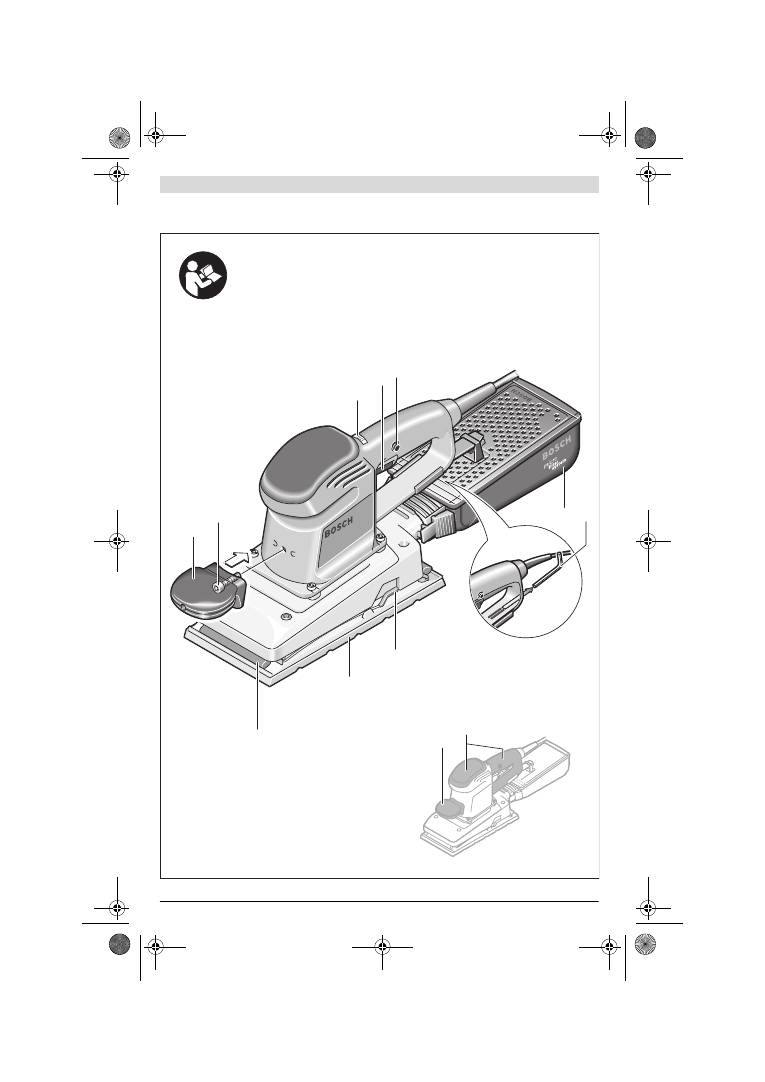
Abgebildete Komponenten
Die Nummerierung der abgebildeten Komponenten bezieht
sich auf die Darstellung des Elektrowerkzeuges auf der Gra-
fikseite.
1
Zusatzgriff (isolierte Grifffläche)*
2
Schraube für Zusatzgriff*
3
Stellrad Schwingzahlvorwahl (GSS 230 AE/
GSS 280 AE)
4
Ein-/Ausschalter
5
Feststelltaste für Ein-/Ausschalter
6
Staubbox komplett (Microfilter System)*
7
Innensechskantschlüssel
8
Klemmbügel
9
Schleifplatte
10
Klemmleiste
11
Handgriff (isolierte Grifffläche)
12
Halterung für Staubbox*
13
Kunststoffschieber
14
Ausblasstutzen
15
Arretierhebel für Staubbox*
16
Filterelement (Microfilter System)*
17
Absaugadapter*
18
Absaugschlauch*
19
Schleifblatt*
20
Lochwerkzeug*
21
Schrauben für Schleifplatte
22
Schleifplatte dünn, verlängert*
23
Schleifblatt, verlängert*
24
Schrauben für verlängerte Schleifplatte*
25
Schleifblatt, dreiecksförmig*
26
Schleifplatte dreiecksförmig, verlängert*
*Abgebildetes oder beschriebenes Zubehör gehört nicht zum
Standard-Lieferumfang. Das vollständige Zubehör finden Sie in
unserem Zubehörprogramm.
OBJ_BUCH-426-005.book Page 7 Thursday, February 2, 2012 10:06 AM
8
| Deutsch
1 619 929 J37 | (2.2.12)
Bosch Power Tools
Technische Daten
Geräusch-/Vibrationsinformation
Messwerte für Geräusch ermittelt entsprechend EN 60745.
Der A-bewertete Schalldruckpegel des Elektrowerkzeugs be-
trägt typischerweise 76 dB(A). Unsicherheit K=3 dB.
Der Geräuschpegel beim Arbeiten kann 80 dB(A) überschrei-
ten.
Gehörschutz tragen!
Schwingungsgesamtwerte a
h
(Vektorsumme dreier Richtun-
gen) und Unsicherheit K ermittelt entsprechend EN 60745:
a
h
=4,5 m/s
2
, K=1,5 m/s
2
.
Der in diesen Anweisungen angegebene Schwingungspegel ist
entsprechend einem in EN 60745 genormten Messverfahren
gemessen worden und kann für den Vergleich von Elektrowerk-
zeugen miteinander verwendet werden. Er eignet sich auch für
eine vorläufige Einschätzung der Schwingungsbelastung.
Der angegebene Schwingungspegel repräsentiert die haupt-
sächlichen Anwendungen des Elektrowerkzeugs. Wenn aller-
dings das Elektrowerkzeug für andere Anwendungen, mit ab-
weichenden Einsatzwerkzeugen oder ungenügender Wartung
eingesetzt wird, kann der Schwingungspegel abweichen.
Dies kann die Schwingungsbelastung über den gesamten Ar-
beitszeitraum deutlich erhöhen.
Für eine genaue Abschätzung der Schwingungsbelastung soll-
ten auch die Zeiten berücksichtigt werden, in denen das Ge-
rät abgeschaltet ist oder zwar läuft, aber nicht tatsächlich im
Einsatz ist. Dies kann die Schwingungsbelastung über den ge-
samten Arbeitszeitraum deutlich reduzieren.
Legen Sie zusätzliche Sicherheitsmaßnahmen zum Schutz
des Bedieners vor der Wirkung von Schwingungen fest wie
zum Beispiel: Wartung von Elektrowerkzeug und Einsatzwerk-
zeugen, Warmhalten der Hände, Organisation der Arbeitsab-
läufe.
Konformitätserklärung
Wir erklären in alleiniger Verantwortung, dass das unter
„Technische Daten“ beschriebene Produkt mit den folgenden
Normen oder normativen Dokumenten übereinstimmt:
EN 60745 gemäß den Bestimmungen der Richtlinien
2011/65/EU, 2004/108/EG, 2006/42/EG.
Technische Unterlagen (2006/42/EG) bei:
Robert Bosch GmbH, PT/ETM9,
D-70745 Leinfelden-Echterdingen
Robert Bosch GmbH, Power Tools Division
D-70745 Leinfelden-Echterdingen
12.01.2012
Montage
f
Ziehen Sie vor allen Arbeiten am Elektrowerkzeug den
Netzstecker aus der Steckdose.
Staub-/Späneabsaugung
f
Stäube von Materialien wie bleihaltigem Anstrich, einigen
Holzarten, Mineralien und Metall können gesundheits-
schädlich sein. Berühren oder Einatmen der Stäube kön-
nen allergische Reaktionen und/oder Atemwegserkran-
kungen des Benutzers oder in der Nähe befindlicher
Personen hervorrufen.
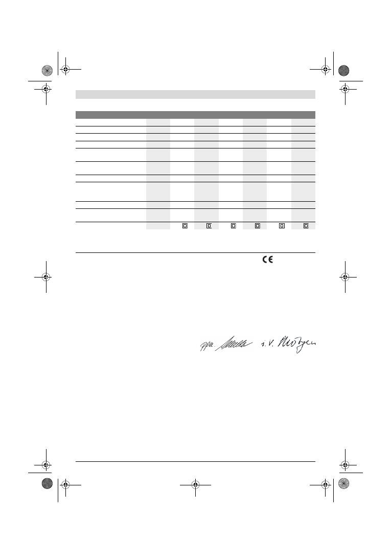
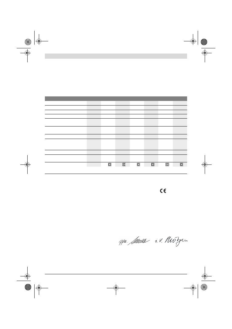
Schwingschleifer
GSS ...
230 A
230 AE
230 AE
280 A
280 AE
280 AE
Sachnummer
0 601 ...
292 0..
292 7..
292 6..
293 0..
293 7..
293 6..
Staubbox im Lieferumfang
–
–
z
–
–
z
Schwingzahlvorwahl
–
z
z
–
z
z
Nennaufnahmeleistung
W
300
300
300
330
330
330
Leerlaufdrehzahl
min
-1
11000
5500
– 11000
5500
– 11000
11000
5500
– 11000
5500
– 11000
Leerlaufschwingzahl
min
-1
22000
11000
– 22000
11000
– 22000
22000
11000
– 22000
11000
– 22000
Schwingkreisdurchmesser
mm
2,4
2,4
2,4
2,4
2,4
2,4
Schleifblattabmessungen
— Kletthaftung
— Klemmspannung
mm
mm
93 x 185
93 x 230
93 x 185
93 x 230
93 x 185
93 x 230
115 x 230
115 x 280
115 x 230
115 x 280
115 x 230
115 x 280
Abmessungen Schleifplatte
mm
92 x 182
92 x 182
92 x 182 114 x 226 114 x 226 114 x 226
Gewicht entsprechend EPTA-Proce-
dure 01/2003
kg
2,3
2,3
2,3
2,6
2,6
2,6
Schutzklasse
/
II
/
II
/
II
/
II
/
II
/
II
Die Angaben gelten für eine Nennspannung [U] von 230 V. Bei abweichenden Spannungen und in länderspezifischen Ausführungen können diese An-
gaben variieren.
Bitte beachten Sie die Sachnummer auf dem Typenschild Ihres Elektrowerkzeugs. Die Handelsbezeichnungen einzelner Elektrowerkzeuge können va-
riieren.
Dr. Egbert Schneider
Senior Vice President
Engineering
Dr. Eckerhard Strötgen
Engineering Director
PT/ESI
OBJ_BUCH-426-005.book Page 8 Thursday, February 2, 2012 10:06 AM

Deutsch |
9
Bosch Power Tools
1 619 929 J37 | (2.2.12)
Bestimmte Stäube wie Eichen- oder Buchenstaub gelten
als krebserzeugend, besonders in Verbindung mit Zusatz-
stoffen zur Holzbehandlung (Chromat, Holzschutzmittel).
Asbesthaltiges Material darf nur von Fachleuten bearbeitet
werden.
– Benutzen Sie möglichst eine für das Material geeignete
Staubabsaugung.
– Sorgen Sie für gute Belüftung des Arbeitsplatzes.
– Es wird empfohlen, eine Atemschutzmaske mit Filter-
klasse P2 zu tragen.
Beachten Sie in Ihrem Land gültige Vorschriften für die zu
bearbeitenden Materialien.
f
Vermeiden Sie Staubansammlungen am Arbeitsplatz.
Stäube können sich leicht entzünden.
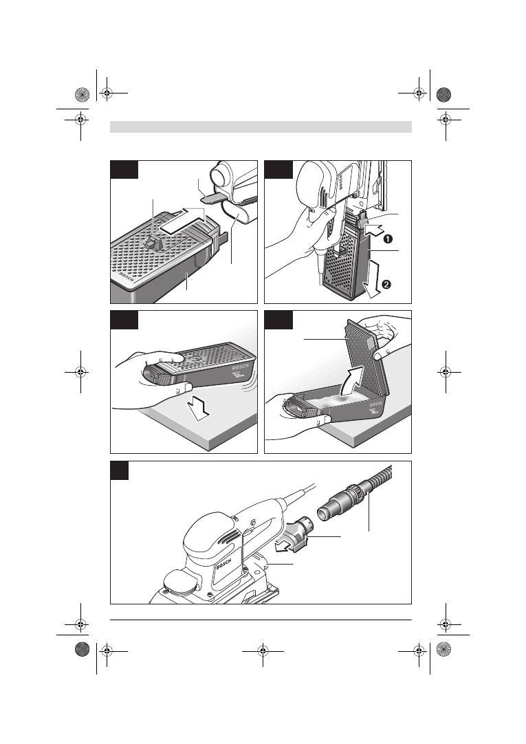
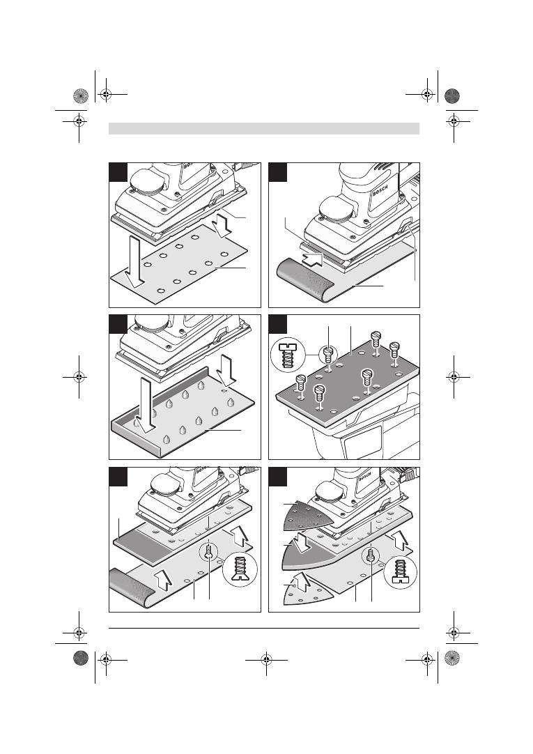
Eigenabsaugung mit Staubbox (siehe Bild A1–A4)
Ziehen Sie vor der Montage der Staubbox
6
den Kunststoff-
schieber
13
heraus. Setzen Sie die Staubbox
6
auf den Aus-
blasstutzen
14
auf, bis sie einrastet. Achten Sie darauf, dass
der Kunststoffschieber
13
in die Halterung
12
eingreift.
Zum Entleeren der Staubbox
6
drücken Sie die Arretierhebel
15
an der Seite der Staubbox (
n
). Ziehen Sie die Staubbox
nach unten ab (
o
).
Vor dem Öffnen der Staubbox
6
sollten Sie mit der Staubbox
wie im Bild gezeigt auf eine feste Unterlage klopfen, um den
Staub vom Filterelement zu lösen.
Fassen Sie die Staubbox
6
an der Griffmulde, klappen Sie das
Filterelement
16
nach oben weg und entleeren Sie die Staub-
box. Reinigen Sie die Lamellen des Filterelements
16
mit ei-
ner weichen Bürste.
Fremdabsaugung (siehe Bild B)
Stecken Sie den Absaugadapter
17
auf den Ausblasstutzen
14
. Achten Sie darauf, dass die Arretierhebel des Absaugad-
apters einrasten. An den Absaugadapter
17
kann ein Absaug-
schlauch mit einem Durchmesser von 19 mm angeschlossen
werden.
Zur Demontage des Absaugadapters
17
drücken Sie dessen
Arretierhebel hinten zusammen und ziehen den Absaugadap-
ter ab.
Der Staubsauger muss für den zu bearbeitenden Werkstoff
geeignet sein.
Verwenden Sie beim Absaugen von besonders gesundheits-
gefährdenden, krebserzeugenden oder trockenen Stäuben
einen Spezialsauger.
Schleifblatt wechseln
Entfernen Sie vor dem Aufsetzen eines neuen Schleifblattes
Schmutz und Staub von der Schleifplatte
9
, z. B. mit einem
Pinsel.
Achten Sie zur Gewährleistung einer optimalen Staub-
absaugung darauf, dass die Ausstanzungen im Schleifblatt
mit den Bohrungen an der Schleifplatte übereinstimmen.
Schleifblätter mit Kletthaftung (siehe Bild C)
Die Schleifplatte
9
ist mit einem Klettgewebe ausgestattet,
damit Sie Schleifblätter mit Kletthaftung schnell und einfach
befestigen können.
Klopfen Sie das Klettgewebe der Schleifplatte
9
vor dem Auf-
setzen des Schleifblattes
19
aus, um eine optimale Haftung zu
ermöglichen.
Setzen Sie das Schleifblatt
19
an einer Seite der Schleifplatte
9
bündig an, legen Sie das Schleifblatt anschließend auf die
Schleifplatte auf und drücken Sie es gut fest.
Zum Abnehmen des Schleifblattes
19
fassen Sie es an einer
Spitze und ziehen Sie es von der Schleifplatte
9
ab.
Schleifblätter ohne Kletthaftung (siehe Bild D)
Heben Sie die Klemmbügel
8
leicht an und hängen Sie diese
aus.
Führen Sie das Schleifblatt
19
bis zum Anschlag unter die ge-
öffnete hintere Klemmleiste
10
und spannen Sie das Schleif-
blatt durch Einhängen des Klemmbügels
8
fest.
Legen Sie das Schleifblatt
19
straff um die Schleifplatte. Füh-
ren Sie das andere Ende des Schleifblattes
19
unter die geöff-
nete vordere Klemmleiste
10
und spannen Sie das Schleif-
blatt durch Einhängen des Klemmbügels
8
fest.
Ungelochte Schleifblätter, z. B. von Rollen- bzw. Meterware,
können Sie für die Staubabsaugung mit dem Lochwerkzeug
20
lochen. Drücken Sie dazu das Elektrowerkzeug mit mon-
tiertem Schleifblatt auf das Lochwerkzeug (siehe Bild E).
Zum Abnehmen des Schleifblattes
19
lösen Sie die Klemmbü-
gel
8
und ziehen das Schleifblatt heraus.
Wahl des Schleifblattes
Entsprechend dem zu bearbeitenden Material und dem ge-
wünschten Abtrag der Oberfläche sind unterschiedliche
Schleifblätter verfügbar:
Körnung
40–400
Zur Bearbeitung sämtlicher
Holzwerkstoffe
Zum Vorschleifen, z.B. von
rauen, ungehobelten Balken und
Brettern
grob
40, 60
Zum Planschleifen und zum
Ebnen kleinerer Unebenheiten
mittel
80, 100, 120
Zum Fertig- und Feinschleifen
harter Hölzer
fein
180, 240,
320, 400
40–320
Zur Bearbeitung von Farb-/
Lackschichten bzw. Grundie-
rungen wie Füller und Spachtel
Zum Abschleifen von Farbe
grob
40, 60
Zum Schleifen von Vorstreich-
farbe
mittel
80, 100, 120
Zum Endschliff von Grundierun-
gen vor der Lackierung
fein
180, 240, 320
OBJ_BUCH-426-005.book Page 9 Thursday, February 2, 2012 10:06 AM

10
| Deutsch
1 619 929 J37 | (2.2.12)
Bosch Power Tools
Schleifplatte wechseln (siehe Bild F)
Die Schleifplatte
9
kann bei Bedarf ausgewechselt werden.
Drehen Sie die 6 Schrauben
21
vollständig heraus und neh-
men Sie die Schleifplatte
9
ab. Setzen Sie die neue Schleif-
platte
9
auf und ziehen Sie die Schrauben wieder fest.
Sonder-Schleifplatten
Sie können die mitgelieferte Schleifplatte
9
gegen eine als Zu-
behör erhältliche Sonder-Schleifplatte auswechseln.
Die Montage der Sonder-Schleifplatte erfolgt entsprechend
dem Wechsel der mitgelieferten Schleifplatte.
Das Aufsetzen und Abnehmen des jeweiligen Schleifblattes
erfolgt entsprechend dem Wechsel des Original-Schleifblat-
tes.
Verlängerte Schleifplatte, rechteckig, dünn (GSS 230 A/
GSS 230 AE) (siehe Bild G)
Die Verwendung der rechteckigen, dünnen, verlängerten
Schleifplatte
22
ermöglicht Ihnen das Schleifen an schwer zu-
gänglichen Stellen und engen Zwischenräumen, wie z. B.
Fenster- und Türlamellen, Nuten oder hinter Heizkörper- und
Wasserrohren.
Zur Montage der rechteckigen, dünnen, verlängerten Schleif-
platte
22
verwenden Sie die zugehörigen Schrauben
24
.
Verlängerte Schleifplatte, dreiecksförmig
(GSS 230 A/GSS 230 AE) (siehe Bild H)
Die Verwendung der dreiecksförmig verlängerten Schleifplat-
te
26
ermöglicht Ihnen das Schleifen in Ecken und Kanten.
Feinschleifplatte (ohne Kletthaftung) (GSS 230 AE/
GSS 280 AE) (siehe Bild D)
Bei überwiegendem Gebrauch von Standard-Schleifblättern
ohne Kletthaftung empfiehlt sich die Verwendung der Fein-
schleifplatte ohne Kletthaftung. Durch ihre plane Schleif-
plattenoberfläche werden insbesondere beim Feinschliff op-
timale Schleifergebnisse erzielt.
Zusatzgriff
Der Zusatzgriff
1
ermöglicht eine bequeme Handhabung und
optimale Kraftverteilung, vor allem bei hohem Schleifabtrag.
Befestigen Sie den Zusatzgriff
1
mit der Schraube
2
am Ge-
häuse.
Betrieb
Inbetriebnahme
f
Beachten Sie die Netzspannung! Die Spannung der
Stromquelle muss mit den Angaben auf dem Typen-
schild des Elektrowerkzeuges übereinstimmen. Mit
230 V gekennzeichnete Elektrowerkzeuge können
auch an 220 V betrieben werden.
Ein-/Ausschalten
Drücken Sie zur
Inbetriebnahme
des Elektrowerkzeuges den
Ein-/Ausschalter
4
und halten Sie ihn gedrückt.
Zum
Feststellen
des gedrückten Ein-/Ausschalters
4
drü-
cken Sie die Feststelltaste
5
.
Um das Elektrowerkzeug
auszuschalten
, lassen Sie den
Ein-/Ausschalter
4
los bzw. wenn er mit der Feststelltaste
5
arretiert ist, drücken Sie den Ein-/Ausschalter
4
kurz und las-
sen ihn dann los.
Schwingzahl vorwählen (GSS 230 AE/GSS 280 AE)
Mit dem Stellrad Schwingzahlvorwahl
3
können Sie die benö-
tigte Schwingzahl auch während des Betriebes vorwählen.
Die erforderliche Schwingzahl ist vom Werkstoff und den Ar-
beitsbedingungen abhängig und kann durch praktischen Ver-
such ermittelt werden.
Arbeitshinweise
f
Warten Sie, bis das Elektrowerkzeug zum Stillstand ge-
kommen ist, bevor Sie es ablegen.
Die Abtragsleistung beim Schleifen wird im Wesentlichen
durch die Wahl des Schleifblattes sowie durch die vorgewähl-
te Schwingzahl (GSS 230 AE/GSS 280 AE) bestimmt.
Nur einwandfreie Schleifblätter bringen gute Schleifleistung
und schonen das Elektrowerkzeug.
Achten Sie auf gleichmäßigen Anpressdruck, um die Lebens-
dauer der Schleifblätter zu erhöhen.
Eine übermäßige Erhöhung des Anpressdruckes führt nicht zu
einer höheren Schleifleistung, sondern zu stärkerem Ver-
schleiß des Elektrowerkzeuges und des Schleifblattes.
Benutzen Sie ein Schleifblatt, mit dem Metall bearbeitet wur-
de, nicht mehr für andere Materialien.
Verwenden Sie nur original Bosch-Schleifzubehör.
Wartung und Service
Wartung und Reinigung
f
Ziehen Sie vor allen Arbeiten am Elektrowerkzeug den
Netzstecker aus der Steckdose.
f
Halten Sie das Elektrowerkzeug und die Lüftungsschlit-
ze sauber, um gut und sicher zu arbeiten.
Wenn ein Ersatz der Anschlussleitung erforderlich ist, dann
ist dies von Bosch oder einer autorisierten Kundendienststel-
le für Bosch-Elektrowerkzeuge auszuführen, um Sicherheits-
gefährdungen zu vermeiden.
Sollte das Elektrowerkzeug trotz sorgfältiger Herstellungs-
und Prüfverfahren einmal ausfallen, ist die Reparatur von ei-
ner autorisierten Kundendienststelle für Bosch-Elektrowerk-
zeuge ausführen zu lassen.
Geben Sie bei allen Rückfragen und Ersatzteilbestellungen
bitte unbedingt die 10-stellige Sachnummer laut Typenschild
des Elektrowerkzeuges an.
Kundendienst und Kundenberatung
Der Kundendienst beantwortet Ihre Fragen zu Reparatur und
Wartung Ihres Produkts sowie zu Ersatzteilen. Explosions-
zeichnungen und Informationen zu Ersatzteilen finden Sie
auch unter:
www.bosch-pt.com
Das Bosch-Kundenberater-Team hilft Ihnen gerne bei Fragen
zu Kauf, Anwendung und Einstellung von Produkten und Zu-
behören.
OBJ_BUCH-426-005.book Page 10 Thursday, February 2, 2012 10:06 AM
English |
11
Bosch Power Tools
1 619 929 J37 | (2.2.12)
www.powertool-portal.de
, das Internetportal für Handwer-
ker und Heimwerker.
www.ewbc.de
, der Informations-Pool für Handwerk und Aus-
bildung.
Deutschland
Robert Bosch GmbH
Servicezentrum Elektrowerkzeuge
Zur Luhne 2
37589 Kalefeld – Willershausen
Tel. Kundendienst: +49 (1805) 70 74 10*
Fax: +49 (1805) 70 74 11*
(*Festnetzpreis 14 ct/min, höchstens 42 ct/min aus Mobil-
funknetzen)
E-Mail: Servicezentrum.Elektrowerkzeuge@de.bosch.com
Tel. Kundenberatung: +49 (1803) 33 57 99
(Festnetzpreis 9 ct/min, höchstens 42 ct/min aus Mobilfunk-
netzen)
Fax: +49 (711) 7 58 19 30
E-Mail: kundenberatung.ew@de.bosch.com
Österreich
Tel.: +43 (01) 7 97 22 20 10
Fax: +43 (01) 7 97 22 20 11
E-Mail: service.elektrowerkzeuge@at.bosch.com
Schweiz
Tel.: +41 (044) 8 47 15 11
Fax: +41 (044) 8 47 15 51
Luxemburg
Tel.: +32 2 588 0589
Fax: +32 2 588 0595
E-Mail: outillage.gereedschap@be.bosch.com
Entsorgung
Elektrowerkzeuge, Zubehör und Verpackungen sollen einer
umweltgerechten Wiederverwertung zugeführt werden.
Werfen Sie Elektrowerkzeuge nicht in den Hausmüll!
Nur für EU-Länder:
Gemäß der Europäischen Richtlinie
2002/96/EG über Elektro- und Elektronik-
Altgeräte und ihrer Umsetzung in nationales
Recht müssen nicht mehr gebrauchsfähige
Elektrowerkzeuge getrennt gesammelt und
einer umweltgerechten Wiederverwertung
zugeführt werden.
Änderungen vorbehalten.
English
Safety Notes
General Power Tool Safety Warnings
Read all safety warnings and all in-
structions.
Failure to follow the warnings
and instructions may result in electric shock, fire and/or seri-
ous injury.
Save all warnings and instructions for future reference.
The term “power tool” in the warnings refers to your mains-
operated (corded) power tool or battery-operated (cordless)
power tool.
Work area safety
f
Keep work area clean and well lit.
Cluttered or dark areas
invite accidents.
f
Do not operate power tools in explosive atmospheres,
such as in the presence of flammable liquids, gases or
dust.
Power tools create sparks which may ignite the dust
or fumes.
f
Keep children and bystanders away while operating a
power tool.
Distractions can cause you to lose control.
Electrical safety
f
Power tool plugs must match the outlet. Never modify
the plug in any way. Do not use any adapter plugs with
earthed (grounded) power tools.
Unmodified plugs and
matching outlets will reduce risk of electric shock.
f
Avoid body contact with earthed or grounded surfaces,
such as pipes, radiators, ranges and refrigerators.
There is an increased risk of electric shock if your body is
earthed or grounded.
f
Do not expose power tools to rain or wet conditions.
Water entering a power tool will increase the risk of electric
shock.
f
Do not abuse the cord. Never use the cord for carrying,
pulling or unplugging the power tool. Keep cord away
from heat, oil, sharp edges and moving parts.
Damaged
or entangled cords increase the risk of electric shock.
f
When operating a power tool outdoors, use an exten-
sion cord suitable for outdoor use.
Use of a cord suitable
for outdoor use reduces the risk of electric shock.
f
If operating a power tool in a damp location is unavoid-
able, use a residual current device (RCD) protected
supply.
Use of an RCD reduces the risk of electric shock.
Personal safety
f
Stay alert, watch what you are doing and use common
sense when operating a power tool. Do not use a power
tool while you are tired or under the influence of drugs,
alcohol or medication.
A moment of inattention while op-
erating power tools may result in serious personal injury.
f
Use personal protective equipment. Always wear eye
protection.
Protective equipment such as dust mask,
non-skid safety shoes, hard hat, or hearing protection
used for appropriate conditions will reduce personal inju-
ries.
f
Prevent unintentional starting. Ensure the switch is in
the off-position before connecting to power source
and/or battery pack, picking up or carrying the tool.
Carrying power tools with your finger on the switch or en-
ergising power tools that have the switch on invites acci-
dents.
f
Remove any adjusting key or wrench before turning
the power tool on.
A wrench or a key left attached to a ro-
tating part of the power tool may result in personal injury.
WARNING
OBJ_BUCH-426-005.book Page 11 Thursday, February 2, 2012 10:06 AM
12
| English
1 619 929 J37 | (2.2.12)
Bosch Power Tools
f
Do not overreach. Keep proper footing and balance at
all times.
This enables better control of the power tool in
unexpected situations.
f
Dress properly. Do not wear loose clothing or jewel-
lery. Keep your hair, clothing and gloves away from
moving parts.
Loose clothes, jewellery or long hair can be
caught in moving parts.
f
If devices are provided for the connection of dust ex-
traction and collection facilities, ensure these are con-
nected and properly used.
Use of dust collection can re-
duce dust-related hazards.
Power tool use and care
f
Do not force the power tool. Use the correct power tool
for your application.
The correct power tool will do the
job better and safer at the rate for which it was designed.
f
Do not use the power tool if the switch does not turn it
on and off.
Any power tool that cannot be controlled with
the switch is dangerous and must be repaired.
f
Disconnect the plug from the power source and/or the
battery pack from the power tool before making any
adjustments, changing accessories, or storing power
tools.
Such preventive safety measures reduce the risk of
starting the power tool accidentally.
f
Store idle power tools out of the reach of children and
do not allow persons unfamiliar with the power tool or
these instructions to operate the power tool.
Power
tools are dangerous in the hands of untrained users.
f
Maintain power tools. Check for misalignment or bind-
ing of moving parts, breakage of parts and any other
condition that may affect the power tool’s operation. If
damaged, have the power tool repaired before use.
Many accidents are caused by poorly maintained power
tools.
f
Keep cutting tools sharp and clean.
Properly maintained
cutting tools with sharp cutting edges are less likely to bind
and are easier to control.
f
Use the power tool, accessories and tool bits etc. in ac-
cordance with these instructions, taking into account
the working conditions and the work to be performed.
Use of the power tool for operations different from those
intended could result in a hazardous situation.
Service
f
Have your power tool serviced by a qualified repair per-
son using only identical replacement parts.
This will en-
sure that the safety of the power tool is maintained.
Safety Warnings for Sander
f
Use the machine only for dry sanding.
Penetration of wa-
ter into the machine increases the risk of an electric shock.
f
Caution, fire hazard! Avoid overheating the object be-
ing sanded as well as the sander. Always empty the
dust collector before taking breaks.
In unfavourable
conditions, e. g., when sparks emit from sanding metals,
sanding debris in the dust bag, micro filter or paper sack
(or in the filter sack or filter of the vacuum cleaner) can
self-ignite. Particularly when mixed with remainders of var-
nish, polyurethane or other chemical materials and when
the sanding debris is hot after long periods of working.
f
When working with the machine, always hold it firmly
with both hands and provide for a secure stance.
The
power tool is guided more secure with both hands.
f
Secure the workpiece.
A workpiece clamped with clamp-
ing devices or in a vice is held more secure than by hand.
Products sold in GB only
: Your product is fitted with an
BS 1363/A approved electric plug with internal fuse (ASTA
approved to BS 1362).
If the plug is not suitable for your socket outlets, it should be
cut off and an appropriate plug fitted in its place by an author-
ised customer service agent. The replacement plug should
have the same fuse rating as the original plug.
The severed plug must be disposed of to avoid a possible
shock hazard and should never be inserted into a mains sock-
et elsewhere.
Products sold in AUS and NZ only
: Use a residual current de-
vice (RCD) with a rated residual current of 30 mA or less.
Product Description and Specifica-
tions
Read all safety warnings and all instruc-
tions.
Failure to follow the warnings and in-
structions may result in electric shock, fire
and/or serious injury.
While reading the operating instructions, unfold the graphics
page for the machine and leave it open.
Intended Use
The machine is intended for dry sanding of wood, plastic, filler
and coated surfaces.
Product Features
The numbering of the product features refers to the illustra-
tion of the machine on the graphics page.
1
Auxiliary handle (insulated gripping surface)*
2
Screw for auxiliary handle*
3
Thumbwheel for orbit frequency preselection
(GSS 230 AE/GSS 280 AE)
4
On/Off switch
5
Lock-on button for On/Off switch
6
Dust box, complete (Microfilter System)*
7
Allen key
8
Sanding-sheet clamp
9
Sanding plate
10
Clamping bracket
11
Handle (insulated gripping surface)
12
Holder for dust box*
13
Plastic slider
14
Extraction outlet
15
Latching lever for dust box*
OBJ_BUCH-426-005.book Page 12 Thursday, February 2, 2012 10:06 AM
English |
13
Bosch Power Tools
1 619 929 J37 | (2.2.12)
16
Filter element (Microfilter System)*
17
Extraction adapter*
18
Vacuum hose*
19
Sanding sheet*
20
Perforating tool*
21
Screws for sanding plate
22
Sanding plate, thin, extended*
23
Sanding plate, extended*
24
Screws for extended sanding plate*
25
Triangular sanding sheet*
26
Triangular sanding plate, extended*
*Accessories shown or described are not part of the standard de-
livery scope of the product. A complete overview of accessories
can be found in our accessories program.
Technical Data
Noise/Vibration Information
Measured sound values determined according to EN 60745.
Typically the A-weighted sound pressure level of the product
is 76 dB(A). Uncertainty K=3 dB.
The noise level when working can exceed 80 dB(A).
Wear hearing protection!
Vibration total values a
h
(triax vector sum) and uncertainty K
determined according to EN 60745:
a
h
=4.5 m/s
2
, K=1.5 m/s
2
.
The vibration emission level given in this information sheet
has been measured in accordance with a standardised test
given in EN 60745 and may be used to compare one tool with
another. It may be used for a preliminary assessment of expo-
sure.
The declared vibration emission level represents the main ap-
plications of the tool. However if the tool is used for different
applications, with different accessories or poorly maintained,
the vibration emission may differ. This may significantly in-
crease the exposure level over the total working period.
An estimation of the level of exposure to vibration should also
take into account the times when the tool is switched off or
when it is running but not actually doing the job. This may sig-
nificantly reduce the exposure level over the total working pe-
riod.
Identify additional safety measures to protect the operator
from the effects of vibration such as: maintain the tool and the
accessories, keep hands warm, organise work patterns.
Declaration of Conformity
We declare under our sole responsibility that the product de-
scribed under “Technical Data” is in conformity with the fol-
lowing standards or standardization documents: EN 60745
according to the provisions of the directives 2011/65/EU,
2004/108/EC, 2006/42/EC.
Technical file (2006/42/EC) at:
Robert Bosch GmbH, PT/ETM9,
D-70745 Leinfelden-Echterdingen
Robert Bosch GmbH, Power Tools Division
D-70745 Leinfelden-Echterdingen
12.01.2012
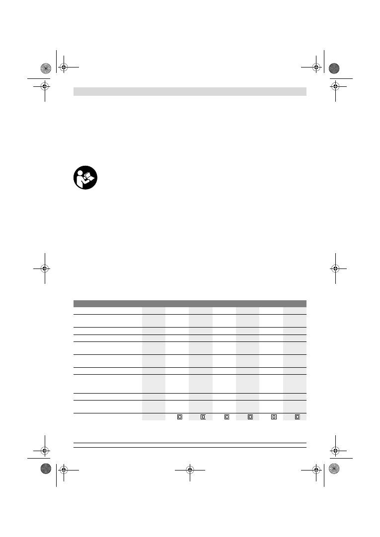
Orbital sander
GSS ...
230 A
230 AE
230 AE
280 A
280 AE
280 AE
Article number
0 601 ...
292 0..
292 7..
292 6..
293 0..
293 7..
293 6..
Dust box included in delivery scope
–
–
z
–
–
z
Preselection of orbital stroke rate
–
z
z
–
z
z
Rated power input
W
300
300
300
330
330
330
No-load speed
min
-1
11000
5500
– 11000
5500
– 11000
11000
5500
– 11000
5500
– 11000
No-load orbital stroke rate
min
-1
22000
11000
– 22000
11000
– 22000
22000
11000
– 22000
11000
– 22000
Orbit diameter
mm
2.4
2.4
2.4
2.4
2.4
2.4
Sanding sheet dimensions
— Adhesion via Velcro backing
— Attachment via clamping
mm
mm
93 x 185
93 x 230
93 x 185
93 x 230
93 x 185
93 x 230
115 x 230
115 x 280
115 x 230
115 x 280
115 x 230
115 x 280
Sanding plate dimensions
mm
92 x 182
92 x 182
92 x 182 114 x 226 114 x 226 114 x 226
Weight according to
EPTA-Procedure 01/2003
kg
2.3
2.3
2.3
2.6
2.6
2.6
Protection class
/
II
/
II
/
II
/
II
/
II
/
II
The values given are valid for a nominal voltage [U] of 230 V. For different voltages and models for specific countries, these values can vary.
Please observe the article number on the type plate of your machine. The trade names of the individual machines may vary.
Dr. Egbert Schneider
Senior Vice President
Engineering
Dr. Eckerhard Strötgen
Engineering Director
PT/ESI
OBJ_BUCH-426-005.book Page 13 Thursday, February 2, 2012 10:06 AM

14
| English
1 619 929 J37 | (2.2.12)
Bosch Power Tools
Assembly
f
Before any work on the machine itself, pull the mains
plug.
Dust/Chip Extraction
f
Dusts from materials such as lead-containing coatings,
some wood types, minerals and metal can be harmful to
one’s health. Touching or breathing-in the dusts can cause
allergic reactions and/or lead to respiratory infections of
the user or bystanders.
Certain dusts, such as oak or beech dust, are considered
as carcinogenic, especially in connection with wood-treat-
ment additives (chromate, wood preservative). Materials
containing asbestos may only be worked by specialists.
– As far as possible, use a dust extraction system suita-
ble for the material.
– Provide for good ventilation of the working place.
– It is recommended to wear a P2 filter-class respirator.
Observe the relevant regulations in your country for the
materials to be worked.
f
Prevent dust accumulation at the workplace.
Dusts can
easily ignite.
Integrated Dust Extraction with Dust Box
(see Fig. A1 – A4)
Before assembling the dust box
6
, pull out the plastic slider
13
. Place the dust box
6
onto the extraction outlet
14
and al-
low it to engage. Make sure that the plastic slider
13
engages
in the holder
12
.
To empty the dust box
6
, press the latching levers
15
on the
side of the dust box (
n
). Pull off the dust box toward the bot-
tom (
o
).
Before opening the dust box
6
, it is recommended to loosen
the dust from the filter element by gently striking it against a
firm support (as shown in the figure).
Grasp the dust box
6
by the recessed grip, fold the filter ele-
ment
16
upward and empty the dust box. Clean the thin
plates of the filter element
16
with a soft brush.
External Dust Extraction (see figure B)
Slide the extraction adapter
17
onto the outlet piece
14
. En-
sure that the latching levers of the extraction adapter engage.
The extraction adapter
17
accepts a vacuum hose with a di-
ameter of 19 mm.
For removal of the extraction adapter
17
, press the latching
levers together at the rear and pull the extraction adapter off.
The vacuum cleaner must be suitable for the material being
worked.
When vacuuming dry dust that is especially detrimental to
health or carcinogenic, use a special vacuum cleaner.
Replacing the Sanding Sheet
When attaching a new sanding sheet, remove any dust or de-
bris from the sanding plate
9
(e. g. with a brush).
To ensure optimum dust extraction, pay attention that the
punched holes in the sanding sheet match with the holes in
the sanding plate.
Sanding Sheets with Velcro Backing (see figure C)
The sanding plate
9
is fitted with Velcro backing for quick and
easy fastening of sanding sheets with Velcro adhesion.
Before attaching the sanding sheet
19
, free the Velcro back-
ing of the sanding plate
9
from any debris by tapping against
it in order to enable optimum adhesion.
Position the sanding sheet
19
flush alongside one edge of the
sanding plate
9
, then lay the sanding sheet onto the sanding
plate and press firmly.
To remove the sanding sheet
19
, grasp it at one of the tips and
pull it off from the sanding plate
9
.
Sanding Sheets without Velcro Backing (see figure D)
Lightly lift and unlatch the sanding-sheet clamp
8
.
Guide the sanding sheet
19
under the opened rear clamping
bracket
10
to the stop and clamp the sanding sheet by rein-
serting the sanding-sheet clamp
8
.
Fold the sanding sheet
19
firmly around the sanding plate.
Guide the other end of the sanding sheet
19
under the open
front clamping bracket
10
and clamp the sanding sheet by re-
inserting the sanding-sheet clamp
8
.
Sanding sheets without holes, e. g. from rolls or by the meter,
can be punctured with the perforating tool
20
for use with
dust extraction. For this, press the machine with the mounted
sanding sheet onto the perforating tool (see figure E).
To remove the sanding sheet
19
, unlatch the sanding-sheet
clamp
8
and pull out the sanding sheet.
Selecting the Sanding Sheet
Depending on the material to be worked and the required rate
of material removal, different sanding sheets are available:
Grain size
40–400
For the working of all wooden
materials
For coarse-sanding, e. g. of
rough, unplaned beams and
boards
coarse 40, 60
For face sanding and planing
small irregularities
medium 80, 100, 120
For finish and fine sanding of hard
woods
fine
180, 240,
320, 400
40–320
For the working of paint/enam-
el coats or primers and fillers
For sanding off paint
coarse 40, 60
For sanding primer
medium 80, 100, 120
For final sanding of primers
before coating
fine
180, 240, 320
OBJ_BUCH-426-005.book Page 14 Thursday, February 2, 2012 10:06 AM

English |
15
Bosch Power Tools
1 619 929 J37 | (2.2.12)
Replacing the Sanding Plate (see figure F)
The sanding plate
9
can be replaced, if required.
Unscrew the 6 screws
21
completely and remove the sanding
plate
9
. Attach the new sanding plate
9
and tighten the screws
again.
Specialty Sanding Plates
You can replace the supplied sanding plate
9
with a specialty
sanding plate, which is available as an accessory.
The specialty sanding plate is attached in the same manner as
the one supplied.
Attach and remove the respective sanding sheets in the same
manner as when changing original sanding sheets.
Extended Sanding Plate, Rectangular, Thin
(GSS 230 A/GSS 230 AE) (see figure G)
Use of the rectangular, thin, extended sanding plate
22
ena-
bles sanding at hard-to-reach locations and narrow interspac-
es, e. g. on window and door sills, grooves or behind radiators
or water pipes.
To mount the rectangular, thin, extended sanding plate
22
,
use the corresponding screws
24
.
Extended Sanding Plate, Triangular
(GSS 230 A/GSS 230 AE) (see figure H)
Use of the extended triangular sanding plate
26
enables sand-
ing in edges and corners.
Finish-sanding Plate (without velcro backing)
(GSS 230 AE/GSS 280 AE) (see figure D)
When operating mainly with standard sanding sheets without
velcro backing, it is recommended to use the finish-sanding
plate without velcro backing. Due to its plane sanding plate
surface, optimum results are achieved, especially for finish
sanding.
Auxiliary Handle
The auxiliary handle
1
enables convenient handling and opti-
mal distribution of power, especially at high removal rates.
Fasten the auxiliary handle
1
with screw
2
to the casing.
Operation
Starting Operation
f
Observe correct mains voltage! The voltage of the pow-
er source must agree with the voltage specified on the
nameplate of the machine. Power tools marked with
230 V can also be operated with 220 V.
Switching On and Off
To
start
the machine, press the On/Off switch
4
and keep it
pressed.
To lock the
pressed
On/Off switch
4
, press the lock-on button
5
.
To
switch off
the machine, release the On/Off switch
4
or
when it is locked with the lock-on button
5
, briefly press the
On/Off switch
4
and then release it.
Preselecting the Orbital Stroke Rate
(GSS 230 AE/GSS 280 AE)
With the thumbwheel for preselection of the orbital stroke
rate
3
, you can preselect the required orbital stroke rate, even
during operation.
The required stroke rate depends on the material and the
working conditions and can be determined through practical
testing.
Working Advice
f
Wait until the machine has come to a standstill before
placing it down.
The removal capacity during sanding is mainly determined by
the selection of the sanding sheet as well as the preselected
orbital stroke rate (GSS 230 AE/GSS 280 AE).
Only flawless sanding sheets achieve good sanding capacity
and extend the service life of the machine.
Pay attention to apply uniform sanding pressure; this increas-
es the working life of the sanding sheets.
Intensifiying the sanding pressure does not lead to an in-
crease of the sanding capacity, but to increased wear of the
machine and the sanding sheet.
A sanding sheet that has been used for metal should not be
used for other materials.
Use only original Bosch sanding accessories.
Maintenance and Service
Maintenance and Cleaning
f
Before any work on the machine itself, pull the mains
plug.
f
For safe and proper working, always keep the machine
and ventilation slots clean.
If the replacement of the supply cord is necessary, this has to
be done by Bosch or an authorized Bosch service agent in or-
der to avoid a safety hazard.
If the machine should fail despite the care taken in manufac-
turing and testing procedures, repair should be carried out by
an after-sales service centre for Bosch power tools.
In all correspondence and spare parts order, please always in-
clude the 10-digit article number given on the type plate of
the machine.
After-sales Service and Customer Assistance
Our after-sales service responds to your questions concern-
ing maintenance and repair of your product as well as spare
parts. Exploded views and information on spare parts can al-
so be found under:
www.bosch-pt.com
Our customer service representatives can answer your ques-
tions concerning possible applications and adjustment of
products and accessories.
OBJ_BUCH-426-005.book Page 15 Thursday, February 2, 2012 10:06 AM
16
| Français
1 619 929 J37 | (2.2.12)
Bosch Power Tools
Great Britain
Robert Bosch Ltd. (B.S.C.)
P.O. Box 98
Broadwater Park
North Orbital Road
Denham
Uxbridge
UB 9 5HJ
Tel. Service: +44 (0844) 736 0109
Fax: +44 (0844) 736 0146
E-Mail: boschservicecentre@bosch.com
Ireland
Origo Ltd.
Unit 23 Magna Drive
Magna Business Park
City West
Dublin 24
Tel. Service: +353 (01) 4 66 67 00
Fax: +353 (01) 4 66 68 88
Australia, New Zealand and Pacific Islands
Robert Bosch Australia Pty. Ltd.
Power Tools
Locked Bag 66
Clayton South VIC 3169
Customer Contact Center
Inside Australia:
Phone: +61 (01300) 307 044
Fax: +61 (01300) 307 045
Inside New Zealand:
Phone: +64 (0800) 543 353
Fax: +64 (0800) 428 570
Outside AU and NZ:
Phone: +61 (03) 9541 5555
www.bosch.com.au
Republic of South Africa
Customer service
Hotline: +27 (011) 6 51 96 00
Gauteng – BSC Service Centre
35 Roper Street, New Centre
Johannesburg
Tel.: +27 (011) 4 93 93 75
Fax: +27 (011) 4 93 01 26
E-Mail: bsctools@icon.co.za
KZN – BSC Service Centre
Unit E, Almar Centre
143 Crompton Street
Pinetown
Tel.: +27 (031) 7 01 21 20
Fax: +27 (031) 7 01 24 46
E-Mail: bsc.dur@za.bosch.com
Western Cape – BSC Service Centre
Democracy Way, Prosperity Park
Milnerton
Tel.: +27 (021) 5 51 25 77
Fax: +27 (021) 5 51 32 23
E-Mail: bsc@zsd.co.za
Bosch Headquarters
Midrand, Gauteng
Tel.: +27 (011) 6 51 96 00
Fax: +27 (011) 6 51 98 80
E-Mail: rbsa-hq.pts@za.bosch.com
Disposal
The machine, accessories and packaging should be sorted for
environmental-friendly recycling.
Do not dispose of power tools into household waste!
Only for EC countries:
According the European Guideline
2002/96/EC for Waste Electrical and Elec-
tronic Equipment and its implementation
into national right, power tools that are no
longer usable must be collected separately
and disposed of in an environmentally cor-
rect manner.
Subject to change without notice.
Français
Avertissements de sécurité
Avertissements de sécurité généraux pour l’outil
Lire tous les avertissements
de sécurité et toutes les ins-
tructions.
Ne pas suivre les avertissements et instructions
peut donner lieu à un choc électrique, un incendie et/ou une
blessure sérieuse.
Conserver tous les avertissements et toutes les instruc-
tions pour pouvoir s’y reporter ultérieurement.
Le terme « outil » dans les avertissements fait référence à vo-
tre outil électrique alimenté par le secteur (avec cordon d’ali-
mentation) ou votre outil fonctionnant sur batterie (sans cor-
don d’alimentation).
Sécurité de la zone de travail
f
Conserver la zone de travail propre et bien éclairée.
Les
zones en désordre ou sombres sont propices aux acci-
dents.
f
Ne pas faire fonctionner les outils électriques en at-
mosphère explosive, par exemple en présence de liqui-
des inflammables, de gaz ou de poussières.
Les outils
électriques produisent des étincelles qui peuvent enflam-
mer les poussières ou les fumées.
f
Maintenir les enfants et les personnes présentes à
l’écart pendant l’utilisation de l’outil.
Les distractions
peuvent vous faire perdre le contrôle de l’outil.
Sécurité électrique
f
Il faut que les fiches de l’outil électrique soient adap-
tées au socle. Ne jamais modifier la fiche de quelque fa-
çon que ce soit. Ne pas utiliser d’adaptateurs avec des
outils à branchement de terre.
Des fiches non modifiées
et des socles adaptés réduiront le risque de choc électri-
que.
AVERTISSEMENT
OBJ_BUCH-426-005.book Page 16 Thursday, February 2, 2012 10:06 AM

Français |
17
Bosch Power Tools
1 619 929 J37 | (2.2.12)
f
Eviter tout contact du corps avec des surfaces reliées à
la terre telles que les tuyaux, les radiateurs, les cuisi-
nières et les réfrigérateurs.
Il existe un risque accru de
choc électrique si votre corps est relié à la terre.
f
Ne pas exposer les outils à la pluie ou à des conditions
humides.
La pénétration d’eau à l’intérieur d’un outil aug-
mentera le risque de choc électrique.
f
Ne pas maltraiter le cordon. Ne jamais utiliser le cordon
pour porter, tirer ou débrancher l’outil. Maintenir le
cordon à l’écart de la chaleur, du lubrifiant, des arêtes
ou des parties en mouvement.
Les cordons endommagés
ou emmêlés augmentent le risque de choc électrique.
f
Lorsqu’on utilise un outil à l’extérieur, utiliser un pro-
longateur adapté à l’utilisation extérieure.
L’utilisation
d’un cordon adapté à l’utilisation extérieure réduit le risque
de choc électrique.
f
Si l’usage d’un outil dans un emplacement humide est
inévitable, utiliser une alimentation protégée par un
dispositif à courant différentiel résiduel (RCD).
L’usage
d’un RCD réduit le risque de choc électrique.
Sécurité des personnes
f
Rester vigilant, regarder ce que vous êtes en train de
faire et faire preuve de bon sens dans l’utilisation de
l’outil. Ne pas utiliser un outil lorsque vous êtes fatigué
ou sous l’emprise de drogues, d’alcool ou de médica-
ments.
Un moment d’inattention en cours d’utilisation
d’un outil peut entraîner des blessures graves des person-
nes.
f
Utiliser un équipement de sécurité. Toujours porter
une protection pour les yeux.
Les équipements de sécu-
rité tels que les masques contre les poussières, les chaus-
sures de sécurité antidérapantes, les casques ou les pro-
tections acoustiques utilisés pour les conditions
appropriées réduiront les blessures des personnes.
f
Eviter tout démarrage intempestif. S’assurer que l’in-
terrupteur est en position arrêt avant de brancher
l’outil au secteur et/ou au bloc de batteries, de le ra-
masser ou de le porter.
Porter les outils en ayant le doigt
sur l’interrupteur ou brancher des outils dont l’interrupteur
est en position marche est source d’accidents.
f
Retirer toute clé de réglage avant de mettre l’outil en
marche.
Une clé laissée fixée sur une partie tournante de
l’outil peut donner lieu à des blessures de personnes.
f
Ne pas se précipiter. Garder une position et un équili-
bre adaptés à tout moment.
Cela permet un meilleur con-
trôle de l’outil dans des situations inattendues.
f
S’habiller de manière adaptée. Ne pas porter de vête-
ments amples ou de bijoux. Garder les cheveux, les vê-
tements et les gants à distance des parties en mouve-
ment.
Des vêtements amples, des bijoux ou les cheveux
longs peuvent être pris dans des parties en mouvement.
f
Si des dispositifs sont fournis pour le raccordement
d’équipements pour l’extraction et la récupération des
poussières, s’assurer qu’ils sont connectés et correcte-
ment utilisés.
Utiliser des collecteurs de poussière peut
réduire les risques dus aux poussières.
Utilisation et entretien de l’outil
f
Ne pas forcer l’outil. Utiliser l’outil adapté à votre appli-
cation.
L’outil adapté réalisera mieux le travail et de maniè-
re plus sûre au régime pour lequel il a été construit.
f
Ne pas utiliser l’outil si l’interrupteur ne permet pas de
passer de l’état de marche à arrêt et vice versa.
Tout
outil qui ne peut pas être commandé par l’interrupteur est
dangereux et il faut le faire réparer.
f
Débrancher la fiche de la source d’alimentation en cou-
rant et/ou le bloc de batteries de l’outil avant tout ré-
glage, changement d’accessoires ou avant de ranger
l’outil.
De telles mesures de sécurité préventives rédui-
sent le risque de démarrage accidentel de l’outil.
f
Conserver les outils à l’arrêt hors de la portée des en-
fants et ne pas permettre à des personnes ne connais-
sant pas l’outil ou les présentes instructions de le faire
fonctionner.
Les outils sont dangereux entre les mains
d’utilisateurs novices.
f
Observer la maintenance de l’outil. Vérifier qu’il n’y a
pas de mauvais alignement ou de blocage des parties
mobiles, des pièces cassées ou toute autre condition
pouvant affecter le fonctionnement de l’outil. En cas de
dommages, faire réparer l’outil avant de l’utiliser.
De
nombreux accidents sont dus à des outils mal entretenus.
f
Garder affûtés et propres les outils permettant de cou-
per.
Des outils destinés à couper correctement entretenus
avec des pièces coupantes tranchantes sont moins sus-
ceptibles de bloquer et sont plus faciles à contrôler.
f
Utiliser l’outil, les accessoires et les lames etc., confor-
mément à ces instructions, en tenant compte des con-
ditions de travail et du travail à réaliser.
L’utilisation de
l’outil pour des opérations différentes de celles prévues
pourrait donner lieu à des situations dangereuses.
Maintenance et entretien
f
Faire entretenir l’outil par un réparateur qualifié utili-
sant uniquement des pièces de rechange identiques.
Cela assurera que la sécurité de l’outil est maintenue.
Instructions de sécurité pour meuleuses
f
N’utiliser l’outil électroportatif que pour un travail à
sec.
La pénétration d’eau dans un outil électroportatif aug-
mente le risque d’un choc électrique.
f
Attention ! Risque d’incendie ! Eviter la surchauffe des
matériaux travaillés et de la ponceuse. Vider toujours
le bac de récupération des poussières avant de faire
une pause de travail.
Les particules de poussière se trou-
vant dans le sac à poussières, le microfiltre, le sac en pa-
pier (ou dans le sac à poussières en tissu ou le filtre de l’as-
pirateur) peuvent s’enflammer d’elles-mêmes dans des
conditions défavorables, p. ex. projection d’étincelles lors
du ponçage de pièces en métal, ceci notamment lorsque
les particules de poussières sont mélangées à des résidus
de vernis, de polyuréthane ou d’autres substances chimi-
ques et que les matériaux travaillés sont très chauds après
avoir été travaillés pendant une période assez longue.
OBJ_BUCH-426-005.book Page 17 Thursday, February 2, 2012 10:06 AM
18
| Français
1 619 929 J37 | (2.2.12)
Bosch Power Tools
f
Toujours bien tenir l’outil électroportatif des deux
mains et veiller à toujours garder une position de tra-
vail stable.
Avec les deux mains, l’outil électroportatif est
guidé de manière plus sûre.
f
Bloquer la pièce à travailler.
Une pièce à travailler serrée
par des dispositifs de serrage appropriés ou dans un étau
est fixée de manière plus sûre que tenue dans les mains.
Description et performances du
produit
Il est impératif de lire toutes les consignes
de sécurité et toutes les instructions.
Le
non-respect des avertissements et instruc-
tions indiqués ci-après peut conduire à une
électrocution, un incendie et/ou de graves
blessures.
Dépliez le volet sur lequel l’appareil est représenté de manière
graphique. Laissez le volet déplié pendant la lecture de la pré-
sente notice d’utilisation.
Utilisation conforme
L’appareil est conçu pour le ponçage à sec des surfaces en
bois, des matières plastiques, du mastic ainsi que des surfa-
ces vernies.
Eléments de l’appareil
La numérotation des éléments de l’appareil se réfère à la re-
présentation de l’outil électroportatif sur la page graphique.
1
Poignée supplémentaire (surface de préhension
isolante)*
2
Vis de la poignée supplémentaire*
3
Molette de réglage présélection de la vitesse
(GSS 230 AE/GSS 280 AE)
4
Interrupteur Marche/Arrêt
5
Bouton de blocage de l’interrupteur Marche/Arrêt
6
Bac de récupération des poussières, complet (Microfil-
ter System)*
7
Clé mâle coudée pour vis à six pans creux
8
Etrier de serrage
9
Plateau de ponçage
10
Réglette à bornes
11
Poignée (surface de préhension isolante)
12
Fixation pour bac de récupération des poussières*
13
Manette en matière plastique
14
Sortie d’aspiration
15
Levier de blocage pour le bac de récupération des
poussières*
16
Filtre (Microfilter System)*
17
Adaptateur d’aspiration*
18
Tuyau d’aspiration*
19
Feuille abrasive*
20
Gabarit de perforation*
21
Vis pour plateau de ponçage
22
Plateau de ponçage rallongé, exécution mince*
23
Feuille abrasive, rallongée*
24
Vis pour plateau de ponçage rallongé*
25
Feuille abrasive, triangulaire*
26
Plateau de ponçage rallongé, triangulaire*
*Les accessoires décrits ou illustrés ne sont pas tous compris dans
la fourniture. Vous trouverez les accessoires complets dans notre
programme d’accessoires.
Caractéristiques techniques
Ponceuse vibrante
GSS ...
230 A
230 AE
230 AE
280 A
280 AE
280 AE
N° d’article
0 601 ...
292 0..
292 7..
292 6..
293 0..
293 7..
293 6..
Bac de récupération de poussières
fourni avec l’appareil
–
–
z
–
–
z
Présélection de la vitesse
–
z
z
–
z
z
Puissance nominale absorbée
W
300
300
300
330
330
330
Vitesse à vide
tr/min
11000
5500
– 11000
5500
– 11000
11000
5500
– 11000
5500
– 11000
Vitesse d’oscillation à vide
min
-1
22000
11000
– 22000
11000
– 22000
22000
11000
– 22000
11000
– 22000
Diamètre d’amplitude d’oscillation
mm
2,4
2,4
2,4
2,4
2,4
2,4
Dimensions feuille abrasive
— Auto-agrippante
— Tension de serrage
mm
mm
93 x 185
93 x 230
93 x 185
93 x 230
93 x 185
93 x 230
115 x 230
115 x 280
115 x 230
115 x 280
115 x 230
115 x 280
Dimensions plaque de ponçage
mm
92 x 182
92 x 182
92 x 182 114 x 226 114 x 226 114 x 226
Poids suivant EPTA-Procedure
01/2003
kg
2,3
2,3
2,3
2,6
2,6
2,6
Classe de protection
/
II
/
II
/
II
/
II
/
II
/
II
Ces indications sont valables pour une tension nominale de [U] 230 V. Ces indications peuvent varier pour des tensions plus basses ainsi que pour des
versions spécifiques à certains pays.
Respectez impérativement le numéro d’article se trouvant sur la plaque signalétique de l’outil électroportatif. Les désignations commerciales des dif-
férents outils électroportatifs peuvent varier.
OBJ_BUCH-426-005.book Page 18 Thursday, February 2, 2012 10:06 AM
Français |
19
Bosch Power Tools
1 619 929 J37 | (2.2.12)
Niveau sonore et vibrations
Valeurs de mesure du niveau sonore relevées conformément
à la norme EN 60745.
Les mesures réelles (A) du niveau de pression acoustique de
l’appareil sont de 76 dB(A). Incertitude K=3 dB.
Lors du travail, le niveau sonore peut dépasser 80 dB(A).
Porter une protection acoustique !
Valeurs totales des vibrations a
h
(somme vectorielle des trois
axes directionnels) et incertitude K relevées conformément à
la norme EN 60745 :
a
h
=4,5 m/s
2
, K=1,5 m/s
2
.
Le niveau d’oscillation indiqué dans ces instructions d’utilisa-
tion a été mesuré conformément à la norme EN 60745 et peut
être utilisé pour une comparaison d’outils électroportatifs. Il
est également approprié pour une estimation préliminaire de
la charge vibratoire.
Le niveau d’oscillation correspond aux utilisations principales
de l’outil électroportatif. Si l’outil électrique est cependant
utilisé pour d’autres applications, avec d’autres outils de tra-
vail ou avec un entretien non approprié, le niveau d’oscillation
peut être différent. Ceci peut augmenter considérablement la
charge vibratoire pendant toute la durée de travail.
Pour une estimation précise de la charge vibratoire, il est re-
commandé de prendre aussi en considération les périodes
pendant lesquelles l’appareil est éteint ou en fonctionnement,
mais pas vraiment utilisé. Ceci peut réduire considérable-
ment la charge vibratoire pendant toute la durée de travail.
Déterminez des mesures de protection supplémentaires pour
protéger l’utilisateur des effets de vibrations, telles que par
exemple : entretien de l’outil électrique et des outils de travail,
maintenir les mains chaudes, organisation judicieuse des
opérations de travail.
Déclaration de conformité
Nous déclarons sous notre propre responsabilité que le pro-
duit décrit sous « Caractéristiques techniques » est en confor-
mité avec les normes ou documents normatifs suivants :
EN 60745 conformément aux termes des réglementations en
vigueur 2011/65/UE, 2004/108/CE, 2006/42/CE.
Dossier technique (2006/42/CE) auprès de :
Robert Bosch GmbH, PT/ETM9,
D-70745 Leinfelden-Echterdingen
Robert Bosch GmbH, Power Tools Division
D-70745 Leinfelden-Echterdingen
12.01.2012
Montage
f
Avant d’effectuer des travaux sur l’outil électroporta-
tif, retirez la fiche de la prise de courant.
Aspiration de poussières/de copeaux
f
Les poussières de matériaux tels que peintures contenant
du plomb, certains bois, minéraux ou métaux, peuvent être
nuisibles à la santé. Entrer en contact ou aspirer les pous-
sières peut entraîner des réactions allergiques et/ou des
maladies respiratoires auprès de l’utilisateur ou de person-
nes se trouvant à proximité.
Certaines poussières telles que les poussières de chêne ou
de hêtre sont considérées comme cancérigènes, surtout
en association avec des additifs pour le traitement du bois
(chromate, lazure). Les matériaux contenant de l’amiante
ne doivent être travaillés que par des personnes qualifiées.
– Si possible, utilisez un dispositif d’aspiration des pous-
sières approprié au matériau.
– Veillez à bien aérer la zone de travail.
– Il est recommandé de porter un masque respiratoire
avec un niveau de filtration de classe P2.
Respectez les règlements spécifiques aux matériaux à trai-
ter en vigueur dans votre pays.
f
Evitez toute accumulation de poussières à l’emplace-
ment de travail.
Les poussières peuvent facilement s’en-
flammer.
Aspiration interne avec bac de récupération des
poussières (voir figure A1 – A4)
Avant de monter le bac de récupération des poussières
6
, re-
tirer la manette en matière plastique
13
. Monter le bac de ré-
cupération des poussières
6
sur la sortie d’aspiration
14
jus-
qu’à ce qu’il s’encliquette. Veiller à ce que la manette en
matière plastique
13
prenne dans la fixation
12
.
Pour vider le bac de récupération des poussières
6
appuyer
sur les leviers de blocage
15
se trouvant sur le côté du bac de
récupération des poussières (
n
). Retirer le bac de récupéra-
tion des poussières vers le bas (
o
).
Avant d’ouvrir le bac de récupération des poussières
6
il est
recommandé de détacher les poussières du filtre en frappant
le bac sur un support stable.
Prenez le bac de récupération des poussières
6
par les poi-
gnées, ouvrez le filtre
16
vers le haut et videz le bac. Nettoyez
les lamelles du filtre
16
à l’aide d’une brosse douce.
Aspiration externe de copeaux (voir figure B)
Monter l’adaptateur d’aspiration
17
sur la sortie d’aspiration
14
. Veiller à ce que les leviers de blocage de l’adaptateur d’as-
piration s’encliquettent. A l’adaptateur d’aspiration
17
il est
possible de brancher un tuyau d’aspiration d’un diamètre de
19 mm.
Pour démonter l’adaptateur d’aspiration
17
presser le levier
de blocage et retirer l’adaptateur d’aspiration.
L’aspirateur doit être approprié au matériau à travailler.
Pour l’aspiration de poussières particulièrement nuisibles à la
santé, cancérigènes ou sèches, utilisez des aspirateurs spéci-
fiques.
Dr. Egbert Schneider
Senior Vice President
Engineering
Dr. Eckerhard Strötgen
Engineering Director
PT/ESI
OBJ_BUCH-426-005.book Page 19 Thursday, February 2, 2012 10:06 AM

20
| Français
1 619 929 J37 | (2.2.12)
Bosch Power Tools
Changement de la feuille abrasive
Avant de monter une nouvelle feuille abrasive, éliminez les
poussières et saletés se trouvant sur le plateau de ponçage
9
à l’aide d’un pinceau p. ex.
Afin de garantir une bonne aspiration de poussières, assurez-
vous que les trous perforés de la feuille abrasive et du plateau
de ponçage coïncident.
Feuilles abrasives auto-agrippantes (voir figure C)
Le plateau de ponçage
9
est équipée d’un revêtement auto-
aggripant, ce qui permet de fixer rapidement et facilement les
feuilles abrasives.
Tapotez légèrement sur le revêtement auto-agrippant du pla-
teau de ponçage
9
avant de monter la feuille abrasive
19
afin
d’obtenir une adhésion optimale.
Placez la feuille abrasive
19
de façon à la faire coïncider avec
un bord du plateau de ponçage
9
et appuyez sur la feuille
abrasive par un léger mouvement de rotation dans le sens des
aiguilles d’une montre.
Pour retirer la feuille abrasive
19
, prenez-la par un coin et re-
tirez-la du plateau de ponçage
9
.
Feuilles abrasives standard (voir figure D)
Soulevz légèrement les étriers de serrage
8
et décrochez-les.
Pousser la feuille abrasive
19
jusqu’à la butée sous la réglette
à bornes arrière ouverte
10
et serrer la feuille abrasive en ac-
crochant l’étrier de serrage
8
.
Placer la feuille abrasive
19
autour du plateau de ponçage jus-
qu’à ce qu’elle soit tendue. Pousser l’autre bout de la feuille
abrasive
19
sous la réglette à bornes avant ouverte
10
et ser-
rer la feuille abrasive en accrochant l’étrier de serrage
8
.
Les feuilles abrasives non perforées, p. ex. marchandise ven-
due au mètre ou sur rouleaux, peuvent être perforées à l’aide
du gabarit de perforation
20
pour l’aspiration de poussières.
Pour ce faire, appuyez l’outil électroportatif, la feuille abrasive
étant montée, sur le gabarit de perforation (voir figure F).
Pour enlever la feuille abrasive
19
, desserrez les étriers de
serrage
8
et sortez la feuille abrasive.
Choix de la feuille abrasive
En fonction du matériau à travailler et du travail demandé, il
existe différentes feuilles abrasives :
Changement du plateau de ponçage
(voir figure F)
Si nécessaire, le plateau de ponçage
9
peut être remplacé.
Desserrer les 6 vis
21
complètement et enlever le plateau de
ponçage
9
. Monter le nouveau plateau de ponçage
9
et res-
serrer les vis.
Plateaux de ponçage spéciaux
Il est possible de remplacer le plateau de ponçage
9
fourni par
un plateau de ponçage spécial disponible comme accessoire.
Le montage du plateau de ponçage spécial s’effectue comme
le remplacement du plateau de ponçage fourni.
Le montage et le démontage de la feuille abrasive correspon-
dante s’effectuent comme le changement de la feuille abrasi-
ve d’origine.
Plateau de ponçage rallongé, rectangulaire, exécution
mince (GSS 230 A/GSS 230 AE) (voir figure G)
Le plateau de ponçage rallongé, rectangulaire, exécution
mince
22
permet de travailler dans des endroits d’accès diffi-
cile et dans des espacements très étroits, par exemple les la-
melles de portes et de fenêtres, les rainures ou derrière les ra-
diateurs ou les tuyaux.
Pour monter le plateau de ponçage rallongé, rectangulaire,
exécution mince
22
, utiliser les vis correspondantes
24
.
Plateau de ponçage rallongé, triangulaire
(GSS 230 A/GSS 230 AE) (voir figure H)
Le plateau de ponçage rallongé triangulaire
26
permet de
poncer dans les coins et les bords.
Plateau de ponçage (sans système auto-agrippant)
(GSS 230 AE/GSS 280 AE) (voir figure D)
Au cas où le travail serait effectué la plupart du temps avec
des feuilles abrasives standard sans système auto-agrippant,
il est recommandé d’utiliser le plateau de ponçage sans systè-
me auto-agrippant. La surface plane du plateau de ponçage
permet d’obtenir des résultats parfaits, notamment en ce qui
concerne les travaux de ponçage.
Poignée supplémentaire
La poignée supplémentaire
1
permet une maniabilité aisée et
un guidage optimal de l’appareil.
Serrer la poignée supplémentaire
1
à l’aide de la vis
2
sur le
boîtier.
Grains
40–400
Pour travailler tous les bois
Pour le dégrossissage p. ex. de
poutres et planches rugueuses,
non rabotées
grossier 40, 60
Pour la rectification (plane) et le
nivellement de petites rugosités
moyen 80, 100, 120
Pour les travaux de finition et le
ponçage fin de bois durs
fin
180, 240,
320, 400
40–320
Pour travailler couches de pein-
ture/vernis ou apprêts comme
p.ex. mastic ou masse de rem-
plissage
Pour retirer des couches de
peinture
grossier 40, 60
Pour poncer des couches de base
de peinture
moyen 80, 100, 120
Pour le finissage d’apprêts avant
l’application de la peinture laquée
fin
180, 240, 320
Grains
OBJ_BUCH-426-005.book Page 20 Thursday, February 2, 2012 10:06 AM
Français |
21
Bosch Power Tools
1 619 929 J37 | (2.2.12)
Mise en marche
Mise en service
f
Tenez compte de la tension du réseau ! La tension de la
source de courant doit correspondre aux indications se
trouvant sur la plaque signalétique de l’outil électro-
portatif. Les outils électroportatifs marqués 230 V
peuvent également fonctionner sur 220 V.
Mise en Marche/Arrêt
Pour
mettre
l’outil électroportatif en marche, appuyez sur
l’interrupteur Marche/Arrêt
4
et maintenez-le appuyé.
Pour
bloquer
l’interrupteur Marche/Arrêt en fonction
4
, ap-
puyez sur le bouton de blocage
5
.
Pour
arrêter
l’appareil électroportatif, relâchez l’interrupteur
Marche/Arrêt
4
ou, s’il est bloqué par le bouton de blocage
5
,
appuyez brièvement sur l’interrupteur Marche/Arrêt
4
, puis
relâchez-le.
Présélection de la vitesse (GSS 230 AE/GSS 280 AE)
La molette de réglage présélection de la vitesse
3
permet de
présélectionner la vitesse nécessaire (même durant le travail
de ponçage).
La vitesse nécessaire dépend du matériau à travailler et des
conditions de travail et peut être déterminée par des essais
pratiques.
Instructions d’utilisation
f
Avant de déposer l’outil électroportatif, attendez que
celui-ci soit complètement à l’arrêt.
L’enlèvement de la matière dépend essentiellement du choix
de la feuille abrasive ainsi que de la vitesse présélectionnée
(GSS 230 AE/GSS 280 AE).
Seules des feuilles abrasives impeccables assurent un bon
travail de ponçage et ménagent l’outil électroportatif.
Veillez à ce que la pression de travail soit régulière, afin d’aug-
menter la durée de vie des feuilles abrasives.
Une pression trop élevée exercée sur l’appareil n’améliore pas
la puissance de ponçage mais augmente considérablement
l’usure de l’outil électroportatif et de la feuille abrasive.
Une feuille abrasive avec laquelle on a travaillé du métal, ne
doit pas être utilisée pour d’autres matériaux.
N’utilisez que des accessoires de ponçage d’origine Bosch.
Entretien et Service Après-Vente
Nettoyage et entretien
f
Avant d’effectuer des travaux sur l’outil électroporta-
tif, retirez la fiche de la prise de courant.
f
Veillez à ce que l’outil électroportatif ainsi que les ouïes
de ventilation soient toujours propres afin d’obtenir un
travail impeccable et sûr.
Dans le cas où un remplacement de la fiche de raccordement
s’avère nécessaire, ceci ne doit être effectué que par Bosch
ou une station de Service Après-Vente agréée pour outillage
Bosch afin d’éviter des dangers de sécurité.
Si, malgré tous les soins apportés à la fabrication et au contrô-
le de l’appareil, celui-ci présentait un défaut, la réparation ne
doit être confiée qu’à une station de Service Après-Vente
agréée pour outillage Bosch.
Pour toute demande de renseignement ou commande de piè-
ces de rechange, précisez-nous impérativement le numéro
d’article à dix chiffres de l’outil électroportatif indiqué sur la
plaque signalétique.
Service Après-Vente et Assistance Des Clients
Notre Service Après-Vente répond à vos questions concer-
nant la réparation et l’entretien de votre produit et les pièces
de rechange. Vous trouverez des vues éclatées ainsi que des
informations concernant les pièces de rechange également
sous :
www.bosch-pt.com
Les conseillers techniques Bosch sont à votre disposition
pour répondre à vos questions concernant l’achat, l’utilisation
et le réglage de vos produits et de leurs accessoires.
France
Vous êtes un utilisateur, contactez :
Le Service Clientèle Bosch Outillage Electroportatif
Tel. : 0 811 36 01 22 (coût d’une communication locale)
Fax : +33 (0) 1 49 45 47 67
E-Mail : contact.outillage-electroportatif@fr.bosch.com
Vous êtes un revendeur, contactez :
Robert Bosch (France) S.A.S.
Service Après-Vente Electroportatif
126, rue de Stalingrad
93705 DRANCY Cédex
Tel. : +33 (0) 1 43 11 90 06
Fax : +33 (0) 1 43 11 90 33
E-Mail : sav.outillage-electroportatif@fr.bosch.com
Belgique, Luxembourg
Tel. : +32 2 588 0589
Fax : +32 2 588 0595
E-Mail : outillage.gereedschap@be.bosch.com
Suisse
Tel. : +41 (044) 8 47 15 12
Fax : +41 (044) 8 47 15 52
Elimination des déchets
Les outils électroportatifs, ainsi que leurs accessoires et em-
ballages, doivent pouvoir suivre chacun une voie de recyclage
appropriée.
Ne jetez pas les outils électroportatifs avec les ordures
ménagères !
Seulement pour les pays de l’Union Européenne :
Conformément à la directive européenne
2002/96/CE relative aux déchets d’équipe-
ments électriques et électroniques et sa mi-
se en vigueur conformément aux législa-
tions nationales, les outils électroportatifs
dont on ne peut plus se servir doivent être
isolés et suivre une voie de recyclage appropriée.
Sous réserve de modifications.
OBJ_BUCH-426-005.book Page 21 Thursday, February 2, 2012 10:06 AM
22
| Español
1 619 929 J37 | (2.2.12)
Bosch Power Tools
Español
Instrucciones de seguridad
Advertencias de peligro generales para herra-
mientas eléctricas
Lea íntegramente estas adverten-
cias de peligro e instrucciones.
En
caso de no atenerse a las advertencias de peligro e instruccio-
nes siguientes, ello puede ocasionar una descarga eléctrica,
un incendio y/o lesión grave.
Guardar todas las advertencias de peligro e instrucciones
para futuras consultas.
El término herramienta eléctrica empleado en las siguientes
advertencias de peligro se refiere a herramientas eléctricas
de conexión a la red (con cable de red) y a herramientas eléc-
tricas accionadas por acumulador (o sea, sin cable de red).
Seguridad del puesto de trabajo
f
Mantenga limpio y bien iluminado su puesto de trabajo.
El desorden o una iluminación deficiente en las áreas de
trabajo pueden provocar accidentes.
f
No utilice la herramienta eléctrica en un entorno con
peligro de explosión, en el que se encuentren combus-
tibles líquidos, gases o material en polvo.
Las herra-
mientas eléctricas producen chispas que pueden llegar a
inflamar los materiales en polvo o vapores.
f
Mantenga alejados a los niños y otras personas de su
puesto de trabajo al emplear la herramienta eléctrica.
Una distracción le puede hacer perder el control sobre la
herramienta eléctrica.
Seguridad eléctrica
f
El enchufe de la herramienta eléctrica debe correspon-
der a la toma de corriente utilizada. No es admisible
modificar el enchufe en forma alguna. No emplear
adaptadores en herramientas eléctricas dotadas con
una toma de tierra.
Los enchufes sin modificar adecuados
a las respectivas tomas de corriente reducen el riesgo de
una descarga eléctrica.
f
Evite que su cuerpo toque partes conectadas a tierra
como tuberías, radiadores, cocinas y refrigeradores.
El
riesgo a quedar expuesto a una sacudida eléctrica es ma-
yor si su cuerpo tiene contacto con tierra.
f
No exponga la herramienta eléctrica a la lluvia y evite
que penetren líquidos en su interior.
Existe el peligro de
recibir una descarga eléctrica si penetran ciertos líquidos
en la herramienta eléctrica.
f
No utilice el cable de red para transportar o colgar la
herramienta eléctrica, ni tire de él para sacar el enchu-
fe de la toma de corriente. Mantenga el cable de red
alejado del calor, aceite, esquinas cortantes o piezas
móviles.
Los cables de red dañados o enredados pueden
provocar una descarga eléctrica.
f
Al trabajar con la herramienta eléctrica a la intemperie
utilice solamente cables de prolongación apropiados
para su uso en exteriores.
La utilización de un cable de
prolongación adecuado para su uso en exteriores reduce el
riesgo de una descarga eléctrica.
f
Si fuese imprescindible utilizar la herramienta eléctri-
ca en un entorno húmedo, es necesario conectarla a
través de un fusible diferencial.
La aplicación de un fusi-
ble diferencial reduce el riesgo a exponerse a una descarga
eléctrica.
Seguridad de personas
f
Esté atento a lo que hace y emplee la herramienta eléc-
trica con prudencia. No utilice la herramienta eléctrica
si estuviese cansado, ni tampoco después de haber
consumido alcohol, drogas o medicamentos.
El no estar
atento durante el uso de la herramienta eléctrica puede
provocarle serias lesiones.
f
Utilice un equipo de protección personal y en todo caso
unas gafas de protección.
El riesgo a lesionarse se reduce
considerablemente si, dependiendo del tipo y la aplicación
de la herramienta eléctrica empleada, se utiliza un equipo
de protección adecuado como una mascarilla antipolvo,
zapatos de seguridad con suela antideslizante, casco, o
protectores auditivos.
f
Evite una puesta en marcha fortuita. Asegurarse de
que la herramienta eléctrica esté desconectada antes
de conectarla a la toma de corriente y/o al montar el
acumulador, al recogerla, y al transportarla.
Si trans-
porta la herramienta eléctrica sujetándola por el interrup-
tor de conexión/desconexión, o si alimenta la herramienta
eléctrica estando ésta conectada, ello puede dar lugar a un
accidente.
f
Retire las herramientas de ajuste o llaves fijas antes de
conectar la herramienta eléctrica.
Una herramienta de
ajuste o llave fija colocada en una pieza rotante puede pro-
ducir lesiones al poner a funcionar la herramienta eléctri-
ca.
f
Evite posturas arriesgadas. Trabaje sobre una base fir-
me y mantenga el equilibrio en todo momento.
Ello le
permitirá controlar mejor la herramienta eléctrica en caso
de presentarse una situación inesperada.
f
Lleve puesta una vestimenta de trabajo adecuada. No
utilice vestimenta amplia ni joyas. Mantenga su pelo,
vestimenta y guantes alejados de las piezas móviles.
La
vestimenta suelta, el pelo largo y las joyas se pueden en-
ganchar con las piezas en movimiento.
f
Siempre que sea posible utilizar unos equipos de aspi-
ración o captación de polvo, asegúrese que éstos estén
montados y que sean utilizados correctamente.
El em-
pleo de estos equipos reduce los riesgos derivados del pol-
vo.
Uso y trato cuidadoso de herramientas eléctricas
f
No sobrecargue la herramienta eléctrica. Use la herra-
mienta eléctrica prevista para el trabajo a realizar.
Con
la herramienta adecuada podrá trabajar mejor y más segu-
ro dentro del margen de potencia indicado.
f
No utilice herramientas eléctricas con un interruptor
defectuoso.
Las herramientas eléctricas que no se pue-
dan conectar o desconectar son peligrosas y deben hacer-
se reparar.
ADVERTENCIA
OBJ_BUCH-426-005.book Page 22 Thursday, February 2, 2012 10:06 AM
Español |
23
Bosch Power Tools
1 619 929 J37 | (2.2.12)
f
Saque el enchufe de la red y/o desmonte el acumulador
antes de realizar un ajuste en la herramienta eléctrica,
cambiar de accesorio o al guardar la herramienta eléc-
trica.
Esta medida preventiva reduce el riesgo a conectar
accidentalmente la herramienta eléctrica.
f
Guarde las herramientas eléctricas fuera del alcance
de los niños. No permita la utilización de la herramienta
eléctrica a aquellas personas que no estén familiariza-
das con su uso o que no hayan leído estas instruccio-
nes.
Las herramientas eléctricas utilizadas por personas
inexpertas son peligrosas.
f
Cuide la herramienta eléctrica con esmero. Controle si
funcionan correctamente, sin atascarse, las partes mó-
viles de la herramienta eléctrica, y si existen partes ro-
tas o deterioradas que pudieran afectar al funciona-
miento de la herramienta eléctrica. Haga reparar estas
piezas defectuosas antes de volver a utilizar la herra-
mienta eléctrica.
Muchos de los accidentes se deben a
herramientas eléctricas con un mantenimiento deficiente.
f
Mantenga los útiles limpios y afilados.
Los útiles mante-
nidos correctamente se dejan guiar y controlar mejor.
f
Utilice la herramienta eléctrica, accesorios, útiles, etc.
de acuerdo a estas instrucciones, considerando en ello
las condiciones de trabajo y la tarea a realizar.
El uso de
herramientas eléctricas para trabajos diferentes de aque-
llos para los que han sido concebidas puede resultar peli-
groso.
Servicio
f
Únicamente haga reparar su herramienta eléctrica por
un profesional, empleando exclusivamente piezas de
repuesto originales.
Solamente así se mantiene la seguri-
dad de la herramienta eléctrica.
Instrucciones de seguridad para lijadoras
f
Solamente emplee la herramienta eléctrica para lijar
en seco.
La penetración de agua en el aparato eléctrico
comporta un mayor riesgo de electrocución.
f
¡Atención! Peligro de incendio. Evite el sobrecalenta-
miento de la pieza y de la propia lijadora. Vacíe siempre
el depósito de polvo antes de cada pausa.
El material en
polvo acumulado en el saco colector de polvo, Microfiltro,
bolsa de papel (o la bolsa filtrante o filtro del aspirador)
puede llegar a autoincendiarse bajo unas condiciones des-
favorables, como, p. ej., al proyectarse chispas al lijar me-
tal. La probabilidad de que esto ocurra es mayor si el mate-
rial va mezclado con partículas de pintura, poliuretano u
otras sustancias químicas y si éste se hubiese calentando
tras un uso intenso de la herramienta.
f
Trabajar sobre una base firme sujetando la herramien-
ta eléctrica con ambas manos.
La herramienta eléctrica
es guiada de forma más segura con ambas manos.
f
Asegure la pieza de trabajo.
Una pieza de trabajo fijada
con unos dispositivos de sujeción, o en un tornillo de ban-
co, se mantiene sujeta de forma mucho más segura que
con la mano.
f
El enchufe macho de conexión, debe ser conectado so-
lamente a un enchufe hembra de las mismas caracteris-
ticas técnicas del enchufe macho en materia.
Descripción y prestaciones del
producto
Lea íntegramente estas advertencias de
peligro e instrucciones.
En caso de no ate-
nerse a las advertencias de peligro e instruc-
ciones siguientes, ello puede ocasionar una
descarga eléctrica, un incendio y/o lesión gra-
ve.
Despliegue y mantenga abierta la solapa con la imagen del
aparato mientras lee las instrucciones de manejo.
Utilización reglamentaria
El aparato ha sido diseñado para lijar en seco madera, plásti-
co, emplastecido y superficies pintadas.
Componentes principales
La numeración de los componentes está referida a la imagen
de la herramienta eléctrica en la página ilustrada.
1
Empuñadura adicional (zona de agarre aislada)*
2
Tornillo para empuñadura adicional*
3
Rueda de ajuste para preselección del nº de oscilaciones
(GSS 230 AE/GSS 280 AE)
4
Interruptor de conexión/desconexión
5
Tecla de enclavamiento del interruptor de conexión/
desconexión
6
Caja colectora de polvo completa (Microfilter System)*
7
Llave macho hexagonal
8
Estribo de apriete
9
Placa lijadora
10
Pieza de apriete
11
Empuñadura (zona de agarre aislada)
12
Soporte de caja colectora de polvo*
13
Corredera de plástico
14
Boquilla de expulsión
15
Palanca de retención de la caja colectora de polvo*
16
Elemento filtrante (Microfilter System)*
17
Adaptador para aspiración de polvo*
18
Manguera de aspiración*
19
Hoja lijadora*
20
Plantilla de perforación*
21
Tornillos para placa lijadora
22
Placa lijadora delgada, alargada*
23
Hoja lijadora, alargada*
24
Tornillos para placa lijadora alargada*
25
Hoja lijadora triangular*
26
Placa lijadora triangular, alargada*
*Los accesorios descritos e ilustrados no corresponden al material
que se adjunta de serie. La gama completa de accesorios opciona-
les se detalla en nuestro programa de accesorios.
OBJ_BUCH-426-005.book Page 23 Thursday, February 2, 2012 10:06 AM

24
| Español
1 619 929 J37 | (2.2.12)
Bosch Power Tools
Datos técnicos
Información sobre ruidos y vibraciones
Ruido determinado según EN 60745.
El nivel de presión sonora típico del aparato, determinado con
un filtro A, es de 76 dB(A). Tolerancia K=3 dB.
El nivel de ruido al trabajar puede llegar a superar 80 dB(A).
¡Utilizar protectores auditivos!
Nivel total de vibraciones a
h
(suma vectorial de tres direccio-
nes) y tolerancia K determinados según EN 60745:
a
h
=4,5 m/s
2
, K=1,5 m/s
2
.
El nivel de vibraciones indicado en estas instrucciones ha sido
determinado según el procedimiento de medición fijado en la
norma EN 60745 y puede servir como base de comparación
con otras herramientas eléctricas. También es adecuado para
estimar provisionalmente la solicitación experimentada por
las vibraciones.
El nivel de vibraciones indicado ha sido determinado para las
aplicaciones principales de la herramienta eléctrica. Por ello,
el nivel de vibraciones puede ser diferente si la herramienta
eléctrica se utiliza para otras aplicaciones, con útiles diferen-
tes, o si el mantenimiento de la misma fuese deficiente. Ello
puede suponer un aumento drástico de la solicitación por vi-
braciones durante el tiempo total de trabajo.
Para determinar con exactitud la solicitación experimentada
por las vibraciones, es necesario considerar también aquellos
tiempos en los que el aparato esté desconectado, o bien, esté
en funcionamiento, pero sin ser utilizado realmente. Ello pue-
de suponer una disminución drástica de la solicitación por vi-
braciones durante el tiempo total de trabajo.
Fije unas medidas de seguridad adicionales para proteger al
usuario de los efectos por vibraciones, como por ejemplo:
Mantenimiento de la herramienta eléctrica y de los útiles, con-
servar calientes las manos, organización de las secuencias de
trabajo.
Declaración de conformidad
Declaramos bajo nuestra responsabilidad, que el producto
descrito bajo “Datos técnicos” está en conformidad con las
normas o documentos normalizados siguientes: EN 60745
de acuerdo con las disposiciones en las directivas
2011/65/UE, 2004/108/CE, 2006/42/CE.
Expediente técnico (2006/42/CE) en:
Robert Bosch GmbH, PT/ETM9,
D-70745 Leinfelden-Echterdingen
Robert Bosch GmbH, Power Tools Division
D-70745 Leinfelden-Echterdingen
12.01.2012
Montaje
f
Antes de cualquier manipulación en la herramienta
eléctrica, sacar el enchufe de red de la toma de corrien-
te.
Aspiración de polvo y virutas
f
El polvo de ciertos materiales como, pinturas que conten-
gan plomo, ciertos tipos de madera y algunos minerales y
metales, puede ser nocivo para la salud. El contacto y la
inspiración de estos polvos pueden provocar en el usuario
o en las personas circundantes reacciones alérgicas y/o
enfermedades respiratorias.
Lijadora orbital
GSS ...
230 A
230 AE
230 AE
280 A
280 AE
280 AE
Nº de artículo
0 601 ...
292 0..
292 7..
292 6..
293 0..
293 7..
293 6..
Caja colectora de polvo, incluida en
el suministro
–
–
z
–
–
z
Preselección del nº de oscilaciones
–
z
z
–
z
z
Potencia absorbida nominal
W
300
300
300
330
330
330
Revoluciones en vacío
min
-1
11000
5500
– 11000
5500
– 11000
11000
5500
– 11000
5500
– 11000
Nº de oscilaciones en vacío
min
-1
22000
11000
– 22000
11000
– 22000
22000
11000
– 22000
11000
– 22000
Diámetro del círculo de oscilación
mm
2,4
2,4
2,4
2,4
2,4
2,4
Dimensiones de la hoja lijadora
— cierre de cardillo
— sujeción a presión
mm
mm
93 x 185
93 x 230
93 x 185
93 x 230
93 x 185
93 x 230
115 x 230
115 x 280
115 x 230
115 x 280
115 x 230
115 x 280
Dimensiones de la placa lijadora
mm
92 x 182
92 x 182
92 x 182 114 x 226 114 x 226 114 x 226
Peso según EPTA-Procedure
01/2003
kg
2,3
2,3
2,3
2,6
2,6
2,6
Clase de protección
/
II
/
II
/
II
/
II
/
II
/
II
Estos datos son válidos para una tensión nominal de [U] 230 V. Los valores pueden variar para otras tensiones y en ejecuciones específicas para cier-
tos países.
Preste atención al nº de artículo en la placa de características de su aparato, ya que las denominaciones comerciales de algunos aparatos pueden variar.
Dr. Egbert Schneider
Senior Vice President
Engineering
Dr. Eckerhard Strötgen
Engineering Director
PT/ESI
OBJ_BUCH-426-005.book Page 24 Thursday, February 2, 2012 10:06 AM

Español |
25
Bosch Power Tools
1 619 929 J37 | (2.2.12)
Ciertos polvos como los de roble, encina y haya son consi-
derados como cancerígenos, especialmente en combina-
ción con los aditivos para el tratamiento de la madera (cro-
matos, conservantes de la madera). Los materiales que
contengan amianto solamente deberán ser procesados
por especialistas.
– A ser posible utilice un equipo para aspiración de polvo
apropiado para el material a trabajar.
– Observe que esté bien ventilado el puesto de trabajo.
– Se recomienda una mascarilla protectora con un filtro
de la clase P2.
Observe las prescripciones vigentes en su país sobre los
materiales a trabajar.
f
Evite acumulaciones de polvo en el puesto de trabajo.
Los materiales en polvo se pueden inflamar fácilmente.
Aspiración propia con caja colectora de polvo
(ver figuras A1 – A4)
Antes de montar la caja colectora de polvo
6
saque primero la
corredera de plástico
13
. Inserte la caja colectora de polvo
6
sobre la boquilla de expulsión
14
hasta enclavarla. Preste
atención a que la corredera de plástico
13
quede alojada en el
soporte
12
.
Para desmontar la caja colectora de polvo
6
presione las pa-
lancas de retención
15
en los laterales de la caja colectora de
polvo (
n
). Extraiga hacia abajo la caja colectora de polvo
(
o
).
Antes de abrir la caja colectora de polvo
6
se aconseja gol-
pearla ligeramente contra una base consistente, tal como se
muestra en la figura, para soltar el polvo del elemento filtran-
te.
Sujete la caja colectora de polvo
6
por la cavidad, abra hacia
arriba el elemento filtrante
16
y vacíe la caja colectora de pol-
vo. Limpie con un cepillo suave las láminas del elemento fil-
trante
16
.
Aspiración externa (ver figura B)
Monte el adaptador para aspiración de polvo
17
en la boquilla
de expulsión
14
. Cuide que enclaven las palancas de reten-
ción del adaptador para aspiración. Al adaptador para aspira-
ción de polvo
17
puede conectarse una manguera de aspira-
ción de un diámetro de 19 mm.
Para desmontar el adaptador para aspiración
17
presione
atrás ambas palancas de retención y extraiga el adaptador pa-
ra aspiración de polvo.
El aspirador debe ser adecuado para el material a trabajar.
Para aspirar polvo especialmente nocivo para la salud, cance-
rígeno, o polvo seco utilice un aspirador especial.
Cambio de la hoja lijadora
Antes de montar una hoja lijadora nueva elimine, p. ej. con un
pincel, la suciedad y el polvo que pudiera estar adherido a la
placa lijadora
9
.
Para que la eficacia en la aspiración de polvo sea óptima, cui-
de que las perforaciones en la hoja lijadora coincidan con los
taladros en la placa lijadora.
Hojas lijadoras con cierre de cardillo (ver figura C)
La placa lijadora
9
va recubierta con un tejido de cardillo (Vel-
cro) que permite sujetar de forma rápida y sencilla las hojas li-
jadoras con cierre de cardillo.
Antes de montar la hoja lijadora
19
sacuda el tejido de cardillo
(Velcro) de la placa lijadora
9
para conseguir una buena adhe-
rencia.
Coloque la hoja lijadora
19
enrasada con uno de los lados de
la placa lijadora
9
, y presione entonces firmemente la hoja li-
jadora contra la placa lijadora.
Para desprender la hoja lijadora
19
de la placa lijadora
9
sujé-
tela por una de sus esquinas y tire de ella.
Hojas lijadoras sin cierre de cardillo (ver figura D)
Alce levemente las palancas de los estribos de apriete
8
y des-
engánchelas.
Inserte hasta el tope la hoja lijadora
19
pasándola por debajo
de la pieza de apriete posterior
10
, y sujete la hoja lijadora en-
ganchando el estribo de apriete
8
.
Coloque la hoja lijadora
19
sobre la placa lijadora cuidando
que quede bien tensa. Inserte el otro extremo de la hoja lijado-
ra
19
pasándola por debajo de la pieza de apriete anterior
10
, y sujete la hoja lijadora enganchando el estribo de apriete
8
.
Las hojas lijadoras sin perforar, p. ej. al cortarlas de pliegos o
material en rollo, pueden perforarse con la plantilla de perfo-
ración
20
. Para ello, presionar la hoja lijadora montada en la
herramienta eléctrica contra la plantilla de perforación
(ver figura E).
Para desmontar la hoja lijadora
19
afloje los estribos de aprie-
te
8
y saque la hoja lijadora.
Selección de la hoja lijadora
De acuerdo al material a trabajar y al arranque de material de-
seado puede seleccionarse entre diversas hojas lijadoras:
Grano
40–400
Para trabajar todo tipo de ma-
dera
Para el lijado previo p. ej. de vigas
y tablas en bruto, sin cepillar
Basto
40, 60
Para planificar e igualar pequeñas
irregularidades
Mediana 80, 100, 120
Para el acabado y lijado fino de
maderas duras
Fino
180, 240,
320, 400
40–320
Para lijar superficies pintadas,
barnizadas, o imprimaciones
con masas de relleno y emplas-
tecido
Para decapar pintura
Basto
40, 60
Para igualar superficies pintadas
después de la primera mano
Mediana 80, 100, 120
Para el lijado final de imprimacio-
nes antes de pintar
Fino
180, 240, 320
OBJ_BUCH-426-005.book Page 25 Thursday, February 2, 2012 10:06 AM

26
| Español
1 619 929 J37 | (2.2.12)
Bosch Power Tools
Cambio de la placa lijadora (ver figura F)
Si fuese necesario, es posible sustituir la placa lijadora
9
.
Desenrosque completamente los 6 tornillos
21
y retire la pla-
ca lijadora
9
. Coloque la placa lijadora nueva
9
y sujétela con
los tornillos.
Placas lijadoras especiales
La placa lijadora
9
que se adjunta con el aparato puede ser
sustituida por las placas lijadoras especiales obtenibles como
accesorio.
El montaje de las placas lijadoras especiales se realiza igual
que al cambiar la placa lijadora adjunta.
El montaje y desmontaje de la hoja lijadora se realiza igual que
la hoja lijadora original.
Placa lijadora rectangular alargada, delgada
(GSS 230 A/GSS 230 AE) (ver figura G)
La placa lijadora rectangular alargada, delgada
22
, le permite
lijar en lugares difícilmente accesibles o en intersticios estre-
chos como, p. ej. láminas de contraventanas o puertas, ranu-
ras o detrás de tuberías de calefacción o agua.
Para montar la placa lijadora rectangular, delgada
22
, emplee
los respectivos tornillos
24
.
Placa lijadora triangular alargada
(GSS 230 A/GSS 230 AE) (ver figura H)
La placa lijadora triangular, alargada
26
, le permite lijar esqui-
nas y cantos.
Placa para lijados finos (sin cierre de cardillo)
(GSS 230 AE/GSS 280 AE) (ver figura D)
En el caso de emplear predominantemente hojas lijadoras es-
tándar sin cierre de cardillo, se recomienda emplear la placa
para lijados finos sin cierre de cardillo. Por ser plana la super-
ficie de la placa lijadora se obtienen unos resultados de lijado
excelentes, especialmente en lijados finos.
Empuñadura adicional
La empuñadura adicional
1
permite un manejo cómodo y una
distribución uniforme de la fuerza, sobre todo, si el arranque
de material es elevado.
Fije la empuñadura adicional
1
con el tornillo
2
a la carcasa.
Operación
Puesta en marcha
f
¡Observe la tensión de red! La tensión de alimentación
deberá coincidir con las indicaciones en la placa de ca-
racterísticas de la herramienta eléctrica. Las herra-
mientas eléctricas marcadas con 230 V pueden funcio-
nar también a 220 V.
Conexión/desconexión
Para la
puesta en marcha
de la herramienta eléctrica accio-
nar y mantener en esa posición el interruptor de conexión/
desconexión
4
.
Para
retener
el interruptor de conexión/desconexión
4
una
vez accionado, presionar la tecla de enclavamiento
5
.
Para
desconectar
la herramienta eléctrica suelte el interrup-
tor de conexión/desconexión
4
, o en caso de estar enclavado
con la tecla
5
, presione brevemente y suelte a continuación el
interruptor de conexión/desconexión
4
.
Preselección del nº de oscilaciones
(GSS 230 AE/GSS 280 AE)
Con la rueda de ajuste
3
puede preseleccionarse el nº de os-
cilaciones, incluso con el aparato en marcha.
El nº de oscilaciones requerido depende del material y condi-
ciones de trabajo y se recomienda por ello determinarlo pro-
bando.
Instrucciones para la operación
f
Antes de depositarla, espere a que la herramienta eléc-
trica se haya detenido completamente.
El rendimiento en el arranque de material obtenido al lijar vie-
ne determinado esencialmente por la hoja lijadora utilizada y
el nº de oscilaciones ajustado (GSS 230 AE/GSS 280 AE).
Únicamente unas hojas lijadoras en buenas condiciones per-
miten conseguir un buen rendimiento en el arranque de mate-
rial además de cuidar la herramienta eléctrica.
Preste atención a ejercer una presión de aplicación uniforme
para prolongar la vida útil de las hojas lijadoras.
Una presión de aplicación excesiva no supone un mayor ren-
dimiento en el arranque de material, sino un mayor desgaste
de la herramienta eléctrica y hoja lijadora.
No emplee una hoja lijadora con la que se ha trabajado metal
para lijar otros tipos de material.
Solamente utilice accesorios para lijar originales Bosch.
Mantenimiento y servicio
Mantenimiento y limpieza
f
Antes de cualquier manipulación en la herramienta
eléctrica, sacar el enchufe de red de la toma de corrien-
te.
f
Mantenga limpia la herramienta eléctrica y las rejillas
de refrigeración para trabajar con eficacia y seguridad.
La sustitución de un cable de conexión deteriorado deberá
ser realizada por Bosch o por un servicio técnico autorizado
para herramientas eléctricas Bosch con el fin de garantizar la
seguridad del aparato.
Si a pesar de los esmerados procesos de fabricación y con-
trol, la herramienta eléctrica llegase a averiarse, la reparación
deberá encargarse a un servicio técnico autorizado para he-
rramientas eléctricas Bosch.
Para cualquier consulta o pedido de piezas de repuesto es im-
prescindible indicar el nº de artículo de 10 dígitos que figura
en la placa de características de la herramienta eléctrica.
OBJ_BUCH-426-005.book Page 26 Thursday, February 2, 2012 10:06 AM
Português |
27
Bosch Power Tools
1 619 929 J37 | (2.2.12)
Servicio técnico y atención al cliente
El servicio técnico le asesorará en las consultas que pueda
Ud. tener sobre la reparación y mantenimiento de su produc-
to, así como sobre piezas de recambio. Los dibujos de despie-
ce e informaciones sobre las piezas de recambio los podrá ob-
tener también en internet bajo:
www.bosch-pt.com
Nuestro equipo de asesores técnicos le orientará gustosa-
mente en cuanto a la adquisición, aplicación y ajuste de los
productos y accesorios.
España
Robert Bosch Espana S.L.U.
Departamento de ventas Herramientas Eléctricas
C/Hermanos García Noblejas, 19
28037 Madrid
Tel. Asesoramiento al cliente: +34 902 53 15 53
Fax: +34 902 53 15 54
Venezuela
Robert Bosch S.A.
Final Calle Vargas. Edf. Centro Berimer P.B.
Boleita Norte
Caracas 107
Tel.: +58 (02) 207 45 11
México
Robert Bosch S. de R.L. de C.V.
Circuito G. Gonzáles Camarena 333
Centro de Ciudad Santa Fe - 01210 - Mexico DF
Tel. Interior: +52 (01) 800 627 1286
Tel. D.F.: +52 (01) 52 84 30 62
E-Mail: arturo.fernandez@mx.bosch.com
Argentina
Robert Bosch Argentina S.A.
Av. Córdoba 5160
C1414BAW Ciudad Autónoma de Buenos Aires
Atención al Cliente
Tel.: +54 (0810) 555 2020
E-Mail: herramientas.bosch@ar.bosch.com
Perú
Robert Bosch S.A.C.
Av. Republica de Panama 4045
Buzón Postal Lima 34 (Surquillo) - Lima
Tel.: +51 1706 1100
Chile
Robert Bosch S.A.
Calle San Eugênio, 40
Ñuñoa - Santiago
Buzón Postal 7750000
Tel.: +56 (02) 520 3100
E-Mail: emasa@emasa.cl
Eliminación
Recomendamos que las herramientas eléctricas, accesorios y
embalajes sean sometidos a un proceso de recuperación que
respete el medio ambiente.
¡No arroje las herramientas eléctricas a la basura!
Sólo para los países de la UE:
Conforme a la Directiva Europea
2002/96/CE sobre aparatos eléctricos y
electrónicos inservibles, tras su transposi-
ción en ley nacional, deberán acumularse
por separado las herramientas eléctricas
para ser sometidas a un reciclaje ecológico.
Reservado el derecho de modificación.
Português
Indicações de segurança
Indicações gerais de advertência para ferramen-
tas eléctricas
Devem ser lidas todas as indicações de
advertência e todas as instruções.
O
desrespeito das advertências e instruções apresentadas
abaixo pode causar choque eléctrico, incêndio e/ou graves le-
sões.
Guarde bem todas as advertências e instruções para futu-
ra referência.
O termo “Ferramenta eléctrica” utilizado a seguir nas indica-
ções de advertência, refere-se a ferramentas eléctricas ope-
radas com corrente de rede (com cabo de rede) e a ferramen-
tas eléctricas operadas com acumulador (sem cabo de rede).
Segurança da área de trabalho
f
Mantenha a sua área de trabalho sempre limpa e bem
iluminada.
Desordem ou áreas de trabalho insuficiente-
mente iluminadas podem levar a acidentes.
f
Não trabalhar com a ferramenta eléctrica em áreas
com risco de explosão, nas quais se encontrem líqui-
dos, gases ou pós inflamáveis.
Ferramentas eléctricas
produzem faíscas, que podem inflamar pós ou vapores.
f
Manter crianças e outras pessoas afastadas da ferra-
menta eléctrica durante a utilização.
No caso de distrac-
ção é possível que perca o controlo sobre o aparelho.
Segurança eléctrica
f
A ficha de conexão da ferramenta eléctrica deve caber
na tomada. A ficha não deve ser modificada de maneira
alguma. Não utilizar uma ficha de adaptação junto com
ferramentas eléctricas protegidas por ligação à terra.
Fichas não modificadas e tomadas apropriadas reduzem o
risco de um choque eléctrico.
f
Evitar que o corpo possa entrar em contacto com su-
perfícies ligadas à terra, como tubos, aquecimentos,
fogões e frigoríficos.
Há um risco elevado devido a cho-
que eléctrico, se o corpo estiver ligado à terra.
MR
P
R
O
D
U
CT
O CERTIFIC
A
D
O
C
E
R
TIF
IED PRO
D
U
C
T
ATENÇÃO
OBJ_BUCH-426-005.book Page 27 Thursday, February 2, 2012 10:06 AM

28
| Português
1 619 929 J37 | (2.2.12)
Bosch Power Tools
f
Manter o aparelho afastado de chuva ou humidade.
A
infiltração de água numa ferramenta eléctrica aumenta o
risco de choque eléctrico.
f
Não deverá utilizar o cabo para outras finalidades. Ja-
mais utilizar o cabo para transportar a ferramenta eléc-
trica, para pendurá-la, nem para puxar a ficha da toma-
da. Manter o cabo afastado de calor, óleo, cantos
afiados ou partes do aparelho em movimento.
Cabos
danificados ou emaranhados aumentam o risco de um cho-
que eléctrico.
f
Se trabalhar com uma ferramenta eléctrica ao ar livre,
só deverá utilizar cabos de extensão apropriados para
áreas exteriores.
A utilização de um cabo de extensão
apropriado para áreas exteriores reduz o risco de um cho-
que eléctrico.
f
Se não for possível evitar o funcionamento da ferra-
menta eléctrica em áreas húmidas, deverá ser utilizado
um disjuntor de corrente de avaria.
A utilização de um
disjuntor de corrente de avaria reduz o risco de um choque
eléctrico.
Segurança de pessoas
f
Esteja atento, observe o que está a fazer e tenha pru-
dência ao trabalhar com a ferramenta eléctrica. Não
utilizar uma ferramenta eléctrica quando estiver fati-
gado ou sob a influência de drogas, álcool ou medica-
mentos.
Um momento de descuido ao utilizar a ferramen-
ta eléctrica, pode levar a lesões graves.
f
Utilizar equipamento de protecção pessoal e sempre
óculos de protecção.
A utilização de equipamento de pro-
tecção pessoal, como máscara de protecção contra pó, sa-
patos de segurança antiderrapantes, capacete de segu-
rança ou protecção auricular, de acordo com o tipo e
aplicação da ferramenta eléctrica, reduz o risco de lesões.
f
Evitar uma colocação em funcionamento involuntária.
Assegure-se de que a ferramenta eléctrica esteja desli-
gada, antes de conectá-la à alimentação de rede e/ou
ao acumulador, antes de levantá-la ou de transportá-la.
Se tiver o dedo no interruptor ao transportar a ferramenta
eléctrica ou se o aparelho for conectado à alimentação de
rede enquanto estiver ligado, poderão ocorrer acidentes.
f
Remover ferramentas de ajuste ou chaves de boca an-
tes de ligar a ferramenta eléctrica.
Uma ferramenta ou
chave que se encontre numa parte do aparelho em movi-
mento pode levar a lesões.
f
Evite uma posição anormal. Mantenha uma posição fir-
me e mantenha sempre o equilíbrio.
Desta forma é mais
fácil controlar a ferramenta eléctrica em situações inespe-
radas.
f
Usar roupa apropriada. Não usar roupa larga nem jóias.
Mantenha os cabelos, roupas e luvas afastadas de par-
tes em movimento.
Roupas frouxas, cabelos longos ou
jóias podem ser agarrados por peças em movimento.
f
Se for possível montar dispositivos de aspiração ou de
recolha, assegure-se de que estejam conectados e uti-
lizados correctamente.
A utilização de uma aspiração de
pó pode reduzir o perigo devido ao pó.
Utilização e manuseio cuidadoso de ferramentas eléctricas
f
Não sobrecarregue o aparelho. Utilize a ferramenta
eléctrica apropriada para o seu trabalho.
É melhor e
mais seguro trabalhar com a ferramenta eléctrica apropri-
ada na área de potência indicada.
f
Não utilizar uma ferramenta eléctrica com um interrup-
tor defeituoso.
Uma ferramenta eléctrica que não pode
mais ser ligada nem desligada, é perigosa e deve ser repa-
rada.
f
Puxar a ficha da tomada e/ou remover o acumulador
antes de executar ajustes no aparelho, de substituir
acessórios ou de guardar o aparelho.
Esta medida de se-
gurança evita o arranque involuntário da ferramenta eléc-
trica.
f
Guardar ferramentas eléctricas não utilizadas fora do
alcance de crianças. Não permita que pessoas que não
estejam familiarizadas com o aparelho ou que não te-
nham lido estas instruções, utilizem o aparelho.
Ferra-
mentas eléctricas são perigosas se forem utilizadas por
pessoas inesperientes.
f
Tratar a ferramenta eléctrica com cuidado. Controlar
se as partes móveis do aparelho funcionam perfeita-
mente e não emperram, e se há peças quebradas ou da-
nificadas que possam prejudicar o funcionamento da
ferramenta eléctrica. Permitir que peças danificadas
sejam reparadas antes da utilização.
Muitos acidentes
têm como causa, a manutenção insuficiente de ferramen-
tas eléctricas.
f
Manter as ferramentas de corte afiadas e limpas.
Ferra-
mentas de corte cuidadosamente tratadas e com cantos
de corte afiados emperram com menos frequência e po-
dem ser conduzidas com maior facilidade.
f
Utilizar a ferramenta eléctrica, acessórios, ferramen-
tas de aplicação, etc. conforme estas instruções. Con-
siderar as condições de trabalho e a tarefa a ser execu-
tada.
A utilização de ferramentas eléctricas para outras
tarefas a não ser as aplicações previstas, pode levar a situ-
ações perigosas.
Serviço
f
Só permita que o seu aparelho seja reparado por pesso-
al especializado e qualificado e só com peças de reposi-
ção originais.
Desta forma é assegurado o funcionamento
seguro do aparelho.
Indicações de segurança para lixadeiras
f
Apenas utilizar a ferramenta eléctrica para o corte a se-
co.
A infiltração de água num aparelho eléctrico aumenta o
risco de choque eléctrico.
f
Atenção, perigo de incêndio! Evitar um sobreaqueci-
mento do material a ser lixado e da lixadeira. Sempre
esvaziar o recipiente de pó antes das pausas de traba-
lho.
Sob condições desfavoráveis é possível que a amola-
dura no saco de pó, no microfiltro, no saco de papel (ou no
saco de filtro ou no filtro do aspirador de pó) seja inflama-
da automaticamente, como voo de faúlhas ao lixar metais.
É especialmente perigoso, se o pó de lixar estiver mistura-
do com restos de verniz, poliuretano ou outros produtos
químicos e o material de lixar tornar-se quente após um pe-
ríodo de trabalho prolongado.
OBJ_BUCH-426-005.book Page 28 Thursday, February 2, 2012 10:06 AM
Português |
29
Bosch Power Tools
1 619 929 J37 | (2.2.12)
f
Segurar a ferramenta eléctrica firmemente com ambas
as mãos durante o trabalho e manter uma posição fir-
me.
A ferramenta eléctrica é conduzida com segurança
com ambas as mãos.
f
Fixar a peça a ser trabalhada.
Uma peça a ser trabalhada
fixa com dispositivos de aperto ou com torno de bancada
está mais firme do que segurada com a mão.
Descrição do produto e da potência
Devem ser lidas todas as indicações de ad-
vertência e todas as instruções.
O desres-
peito das advertências e instruções apresen-
tadas abaixo pode causar choque eléctrico,
incêndio e/ou graves lesões.
Abrir a página basculante contendo a apresentação do apare-
lho, e deixar esta página aberta enquanto estiver lendo a ins-
trução de serviço.
Utilização conforme as disposições
O aparelho é destinado para cortar a seco em madeira, plásti-
co, massa de aparelhar, assim como em superfícies enverni-
zadas.
Componentes ilustrados
A numeração dos componentes ilustrados refere-se à apre-
sentação da ferramenta eléctrica na página de esquemas.
1
Punho adicional (superfície isolada)*
2
Parafuso para o punho adicional*
3
Roda de ajuste para a pré-selecção do número de
oscilações (GSS 230 AE/GSS 280 AE)
4
Interruptor de ligar-desligar
5
Tecla de fixação para o interruptor de ligar-desligar
6
Caixa de pó completa (Microfilter System)*
7
Chave de sextavado interno
8
Braçadeira de aperto
9
Placa de lixar
10
Régua de bornes
11
Punho (superfície isolada)
12
Fixação da caixa de pó*
13
Corrediça de plástico
14
Bocais de sopro
15
Alavanca de travamento para caixa de pó*
16
Elemento do filtro (Microfilter System)*
17
Adaptador de aspiração*
18
Mangueira de aspiração*
19
Folha de lixar*
20
Ferramenta para puncionar*
21
Parafusos para a placa abrasiva
22
Placa de lixar fina, prolongada*
23
Placa de lixar, prolongada*
24
Parafusos para a placa abrasiva prolongada*
25
Lixa, triangular*
26
Placa de lixar triangular, prolongada*
*Acessórios apresentados ou descritos não pertencem ao volume
de fornecimento padrão. Todos os acessórios encontram-se no
nosso programa de acessórios.
Dados técnicos
Lixadeira orbital
GSS ...
230 A
230 AE
230 AE
280 A
280 AE
280 AE
N° do produto
0 601 ...
292 0..
292 7..
292 6..
293 0..
293 7..
293 6..
Caixa de pó no volume de forneci-
mento
–
–
z
–
–
z
Pré-selecção do número de
oscilações
–
z
z
–
z
z
Potência nominal consumida
W
300
300
300
330
330
330
N° de rotações em ponto morto
min
-1
11000
5500
– 11000
5500
– 11000
11000
5500
– 11000
5500
– 11000
N° de oscilações em vazio
min
-1
22000
11000
– 22000
11000
– 22000
22000
11000
– 22000
11000
– 22000
Diâmetro do circulo de oscilação
mm
2,4
2,4
2,4
2,4
2,4
2,4
Dimensões da folha de lixar
— Aderência de velcro
— Tensão de aperto
mm
mm
93 x 185
93 x 230
93 x 185
93 x 230
93 x 185
93 x 230
115 x 230
115 x 280
115 x 230
115 x 280
115 x 230
115 x 280
Dimensões da placa de lixar
mm
92 x 182
92 x 182
92 x 182 114 x 226 114 x 226 114 x 226
Peso conforme EPTA-Procedure
01/2003
kg
2,3
2,3
2,3
2,6
2,6
2,6
Classe de protecção
/
II
/
II
/
II
/
II
/
II
/
II
As indicações valem para tensões nominais [U] de 230 V. Estas indicações podem variar dependendo de tensões inferiores e dos modelos específicos
dos países.
Observar o número de produto na placa de características da sua ferramenta eléctrica. A designação comercial das ferramentas eléctricas individuais
pode variar.
OBJ_BUCH-426-005.book Page 29 Thursday, February 2, 2012 10:06 AM
30
| Português
1 619 929 J37 | (2.2.12)
Bosch Power Tools
Informação sobre ruídos/vibrações
Valores de medição para ruídos, averiguados conforme
EN 60745.
O nível de pressão acústica avaliado como A do aparelho é
tipicamente 76 dB(A). Incerteza K=3 dB.
O nível de ruído durante o trabalho pode ultrapassar
80 dB(A).
Usar protecção auricular!
Totais valores de vibrações a
h
(soma dos vectores de três di-
recções) e incerteza K averiguada conforme EN 60745:
a
h
=4,5 m/s
2
, K=1,5 m/s
2
.
O nível de oscilações indicado nestas instruções de serviço
foi medido de acordo com um processo de medição normali-
zado pela norma EN 60745 e pode ser utilizado para a com-
paração de aparelhos. Ele também é apropriado para uma
avaliação provisória da carga de vibrações.
O nível de vibrações indicado representa as aplicações princi-
pais da ferramenta eléctrica. Se a ferramenta eléctrica for uti-
lizada para outras aplicações, com outras ferramentas de tra-
balho ou com manutenção insuficiente, é possível que o nível
de vibrações seja diferente. Isto pode aumentar sensivelmen-
te a carga de vibrações para o período completo de trabalho.
Para uma estimação exacta da carga de vibrações, também
deveriam ser considerados os períodos nos quais o aparelho
está desligado ou funciona, mas não está sendo utilizado. Isto
pode reduzir a carga de vibrações durante o completo perío-
do de trabalho.
Além disso também deverão ser estipuladas medidas de se-
gurança para proteger o operador contra o efeito de vibra-
ções, como por exemplo: Manutenção de ferramentas eléctri-
cas e de ferramentas de trabalho, manter as mãos quentes e
organização dos processos de trabalho.
Declaração de conformidade
Declaramos sob nossa exclusiva responsabilidade que o pro-
duto descrito em “Dados técnicos” cumpre as seguintes nor-
mas ou documentos normativos: EN 60745 conforme as dis-
posições das directivas 2011/65/UE, 2004/108/CE,
2006/42/CE.
Processo técnico (2006/42/CE) em:
Robert Bosch GmbH, PT/ETM9,
D-70745 Leinfelden-Echterdingen
Robert Bosch GmbH, Power Tools Division
D-70745 Leinfelden-Echterdingen
12.01.2012
Montagem
f
Antes de todos trabalhos na ferramenta eléctrica deve-
rá puxar a ficha de rede da tomada.
Aspiração de pó/de aparas
f
Pós de materiais como por exemplo, tintas que contém
chumbo, alguns tipos de madeira, minerais e metais, po-
dem ser nocivos à saúde. O contacto ou a inalação dos pós
pode provocar reações alérgicas e/ou doenças nas vias
respiratórias do utilizador ou das pessoas que se encon-
trem por perto.
Certos pós, como por exemplo pó de carvalho e faia são
considerados como sendo cancerígenos, especialmente
quando juntos com substâncias para o tratamento de ma-
deiras (cromato, preservadores de madeira). Material que
contém asbesto só deve ser processado por pessoal espe-
cializado.
– Se possível deverá usar um dispositivo de aspiração
apropriado para o material.
– Assegurar uma boa ventilação do local de trabalho.
– É recomendável usar uma máscara de protecção respi-
ratória com filtro da classe P2.
Observe as directivas para os materiais a serem trabalha-
dos, vigentes no seu país.
f
Evite o acúmulo de pó no local de trabalho.
Pós podem
entrar levemente em ignição.
Aspiração própria com a caixa de pó (veja figura A1 – A4)
Antes de montar a caixa de pó
6
deverá puxar a corrediça de
plástico
13
para fora. Colocar a caixa de pó
6
sobre o bocal de
sopro
14
até engatar. Observe que a corrediça de plástico
13
engate na fixação
12
.
Para esvaziar a caixa de pó
6
pressionar as teclas de trava-
mento
15
na lateral da caixa de pó (
n
). Retirar a caixa de pó
puxando para baixo (
o
).
Antes de abrir a caixa de pó
6
deveria dar umas batidelas com
a caixa de pó sobre uma base firme, como indicado na figura,
para soltar o pó do elemento do filtro.
Segurar a caixa de pó
6
pela cavidade do punho, abrir o ele-
mento do filtro
16
para cima e desvaziar a caixa de pó. Limpar
as lamelas do elemento do filtro
16
com uma escova macia.
Aspiração externa (veja figura B)
Introduzir o adaptador de aspiração
17
sobre o bocal de so-
pro
14
. Observar que as alavancas de travamento do adapta-
dor de aspiração engatem. Ao adaptador de aspiração
17
é
possível conectar uma mangueira de aspiração com um diâ-
metro de 19 mm.
Para desmontar o adaptador de aspiração
17
deverá pressio-
nar a respectiva alavanca de travamento do lado posterior e
puxar o adaptador de aspiração.
O aspirador de pó deve ser apropriado para o material a ser
trabalhado.
Utilizar um aspirador especial para aspirar pó que seja extre-
mamente nocivo à saúde, cancerígeno ou seco.
Substituir a folha de lixar
Remover sujidade e pó da placa de lixar antes de colocar uma
nova placa de lixar
9
, p. ex. com um pincel.
Para assegurar uma aspiração de pó ideal, deverá observar
que os recortes na folha de lixar coincidam com os orifícios na
placa de lixar.
Dr. Egbert Schneider
Senior Vice President
Engineering
Dr. Eckerhard Strötgen
Engineering Director
PT/ESI
OBJ_BUCH-426-005.book Page 30 Thursday, February 2, 2012 10:06 AM
Português |
31
Bosch Power Tools
1 619 929 J37 | (2.2.12)
Folhas de lixar com aderência de velcro (veja figura C)
A placa de lixar
9
está equipada com um tecido de velcro, para
uma fixação rápida de simples de folhas de lixar com aderên-
cia de velcro.
Sacudir o tecido de velcro da placa de lixar
9
antes de colocar
a folha de lixar
19
para possibilitar uma aderência ideal.
Posicionar a folha de lixar
19
de forma alinhada num dos la-
dos da placa de lixar
9
, e agora premir bem a folha de lixar so-
bre a placa de lixar.
Para retirar a folha de lixar
19
deverá segurá-la por um a ponta
e puxá-la da placa de lixar
9
.
Folhas de lixar sem aderência de velcro (veja figura D)
Elevar levemente os arcos de aperto
8
e desprendê-los.
Conduzir a folha de lixar
19
completamente sob a barra de
aperto traseira
10
aberta e fixar a folha de lixar com o arco de
aperto
8
.
Colocar a folha de lixar
19
bem esticada sobre a placa de lixar.
Conduzir a outra extremidade da folha de lixar
19
sob a barra
de aperto dianteira
10
aberta e fixar a folha de lixar com o ar-
co de aperto
8
.
Folhas de lixar sem furos, p. ex. de rolos ou ao metro, podem
ser perfuradas com um aparelho de puncionar
20
. Para tal de-
verá pressionar a ferramenta eléctrica com a folha de lixar
montada sobre a ferramenta para puncionar (veja figura E).
Para retirar a folha de lixar
19
, deverá soltar o arco de aperto
8
e puxar a folha de lixar para fora.
Selecção da folha de lixar
Estão disponíveis diversas folhas de lixar, de acordo com o
material a ser trabalhado e com o desbaste desejado da su-
perfície:
Substituir a placa de lixar (veja figura F)
Se necessário, é possível trocar a placa de lixar
9
.
Desaparafusar completamente os 6 parafusos
21
e retirar a
placa de lixar
9
. Colocar a nova placa de lixar
9
e reapertar os
parafusos.
Placas de lixar especiais
É possível substituir a placa de lixar fornecida
9
por uma placa
de lixar especial, adquirível como acessório.
A montagem da placa de lixar especial é realizada conforme a
substituição da placa de lixar fornecida.
Para colocar e para retirar a respectiva folha de lixar, deverá
proceder conforme a substituição da placa de lixar original.
Placa de lixar prolongada, rectangular, fina
(GSS 230 A/GSS 230 AE) (veja figura G)
Com uma placa de lixar rectangular, fina e prolongada
22
é
possível lixar em locais de difícil acesso e em espaços estrei-
tos, como p. ex. em lamelas de janelas e portas, ranhuras ou
tubos de aquecimentos e de água.
Para a montagem de placas rectangulares, finas e prolonga-
das
22
deverão ser usados os respectivos parafusos
24
.
Placa de lixar prolongada, triangular
(GSS 230 A/GSS 230 AE) (veja figura H)
Com a placa de lixar triangular prolongada
26
é possível lixar
em cantos e arestas.
Placa para rectificação fina (sem aderência de velcro)
(GSS 230 AE/GSS 280 AE) (veja figura D)
Se forem principalmente utilizadas lixas padrões sem velcro,
é recomendável utilizar uma placa para rectificação fina sem
aderência de velcro. Devido à sua superfície abrasiva plana,
são alcançados resultados optimizados, especialmente em
trabalhos de acabamento (rectificação fina).
Punho adicional
O punho adicional
1
possibilita um manuseio confortável e
uma distribuição de força optimizada, especialmente no caso
de uma forte remoção por rectificação.
Fixar o punho adicional
1
com o parafuso
2
à carcaça.
Funcionamento
Colocação em funcionamento
f
Observar a tensão de rede! A tensão da fonte de corren-
te deve coincidir com a indicada na chapa de identifica-
ção da ferramenta eléctrica. Ferramentas eléctricas
marcadas para 230 V também podem ser operadas
com 220 V.
Ligar e desligar
Para a
colocação em funcionamento
da ferramenta eléctrica
deverá pressionar o interruptor de ligar-desligar
4
e manter
pressionado.
Para
fixar
o interruptor de ligar-desligar
4
deverá premir a te-
cla de fixação
5
.
Grão
40–400
Para processar todos
materiais de madeira
Para a rectificação prévia de
p. ex. vigas e tábuas ásperas e
não aplainadas
grosseiro 40, 60
Para lixamento plano e para
nivelar pequenas rugosidades
médio
80, 100, 120
Para o acabamento fino de lixar
madeiras duras
fino
180, 240,
320, 400
40–320
Para o processamento de ca-
madas de tintas e vernizes ou
primeira demão como betume
de enchimento e massa de
aparelhar
Para lixar tinta
grosseiro 40, 60
Para lixar tinta de primeira
demão
médio
80, 100, 120
Para o acabamento final de
primeiras demãos antes de
envernizar
fino
180, 240,
320
OBJ_BUCH-426-005.book Page 31 Thursday, February 2, 2012 10:06 AM
32
| Italiano
1 619 929 J37 | (2.2.12)
Bosch Power Tools
Para
desligar
a ferramenta eléctrica, deverá soltar o interrup-
tor de ligar-desligar
4
ou se estiver travado com a tecla de fi-
xação
5
, deverá pressionar o interruptor de ligar-desligar
4
por instantes e em seguida soltar novamente.
Pré-seleccionar o número de oscilações
(GSS 230 AE/GSS 280 AE)
Com a roda de pré-selecção do número de oscilações
3
é pos-
sível pré-seleccionar o número de oscilações necessário du-
rante o funcionamento.
O n° de oscilações necessário depende do material e das con-
dições de trabalho e pode ser verificado através de ensaios
práticos.
Indicações de trabalho
f
Espere a ferramenta eléctrica parar completamente,
antes de depositá-la.
A potência abrasiva ao lixar depende principalmente da selec-
ção da folha de lixar, assim como do número de oscilação
(GSS 230 AE/GSS 280 AE) pré-seleccionado.
Apenas folhas de lixar em perfeito estado proporcionam uma
perfeita potência abrasiva e poupam a ferramenta eléctrica.
Trabalhar com uma força de pressão uniforme para aumentar
a vida útil das folhas de lixar.
Um aumento demasiado da força de pressão não leva a uma
potência abrasiva mais alta, mas a um desgaste mais forte da
ferramenta eléctrica e da folha de lixar.
Jamais utilizar uma folha de serra com a qual foi processado
metal, para processar outros materiais.
Só utilizar acessórios de lixar originais Bosch.
Manutenção e serviço
Manutenção e limpeza
f
Antes de todos trabalhos na ferramenta eléctrica deve-
rá puxar a ficha de rede da tomada.
f
Manter a ferramenta eléctrica e as aberturas de venti-
lação sempre limpas, para trabalhar bem e de forma se-
gura.
Se for necessário substituir o cabo de conexão, isto deverá
ser realizado pela Bosch ou por uma oficina de serviço pós-
venda autorizada para todas as ferramentas eléctricas Bosch
para evitar riscos de segurança.
Se a ferramenta eléctrica falhar apesar de cuidadosos proces-
sos de fabricação e de teste, a reparação deverá ser executa-
da por uma oficina de serviço autorizada para ferramentas
eléctricas Bosch.
Para todas as questões e encomendas de peças sobressalen-
tas é imprescindível indicar o número de produto de
10 dígitos como consta na placa de características da ferra-
menta eléctrica.
Serviço pós-venda e assistência ao cliente
O serviço pós-venda responde às suas perguntas a respeito
de serviços de reparação e de manutenção do seu produto,
assim como das peças sobressalentes. Desenhos explodidos
e informações sobre peças sobressalentes encontram-se em:
www.bosch-pt.com
A nossa equipa de consultores Bosch esclarece com prazer
todas as suas dúvidas a respeito da compra, aplicação e ajus-
te dos produtos e acessórios.
Portugal
Robert Bosch LDA
Avenida Infante D. Henrique
Lotes 2E – 3E
1800 Lisboa
Tel.: +351 (021) 8 50 00 00
Fax: +351 (021) 8 51 10 96
Brasil
Robert Bosch Ltda.
Caixa postal 1195
13065-900 Campinas
Tel.: +55 (0800) 70 45446
www.bosch.com.br/contacto
Eliminação
Ferramentas eléctricas, acessórios e embalagens devem ser
enviados a uma reciclagem ecológica de matérias primas.
Não deitar ferramentas eléctricas no lixo doméstico!
Apenas países da União Europeia:
De acordo com a directiva europeia
2002/96/CE para aparelhos eléctricos e
electrónicos velhos, e com as respectivas
realizações nas leis nacionais, as ferramen-
tas eléctricas que não servem mais para a
utilização, devem ser enviadas separada-
mente a uma reciclagem ecológica.
Sob reserva de alterações.
Italiano
Norme di sicurezza
Avvertenze generali di pericolo per elettroutensili
Leggere tutte le avvertenze di pe-
ricolo e le istruzioni operative.
In
caso di mancato rispetto delle avvertenze di pericolo e delle
istruzioni operative si potrà creare il pericolo di scosse elettri-
che, incendi e/o incidenti gravi.
Conservare tutte le avvertenze di pericolo e le istruzioni
operative per ogni esigenza futura.
Il termine «elettroutensile» utilizzato nelle avvertenze di peri-
colo si riferisce ad utensili elettrici alimentati dalla rete (con li-
nea di allacciamento) ed ad utensili elettrici alimentati a bat-
teria (senza linea di allacciamento).
AVVERTENZA
OBJ_BUCH-426-005.book Page 32 Thursday, February 2, 2012 10:06 AM

Italiano |
33
Bosch Power Tools
1 619 929 J37 | (2.2.12)
Sicurezza della postazione di lavoro
f
Tenere la postazione di lavoro sempre pulita e ben illu-
minata.
Il disordine oppure zone della postazione di lavoro
non illuminate possono essere causa di incidenti.
f
Evitare d’impiegare l’elettroutensile in ambienti sog-
getti al rischio di esplosioni nei quali si abbia presenza
di liquidi, gas o polveri infiammabili.
Gli elettroutensili
producono scintille che possono far infiammare la polvere
o i gas.
f
Tenere lontani i bambini ed altre persone durante l’im-
piego dell’elettroutensile.
Eventuali distrazioni potranno
comportare la perdita del controllo sull’elettroutensile.
Sicurezza elettrica
f
La spina di allacciamento alla rete dell’elettroutensile
deve essere adatta alla presa. Evitare assolutamente di
apportare modifiche alla spina. Non impiegare spine
adattatrici assieme ad elettroutensili dotati di collega-
mento a terra.
Le spine non modificate e le prese adatte
allo scopo riducono il rischio di scosse elettriche.
f
Evitare il contatto fisico con superfici collegate a terra,
come tubi, riscaldamenti, cucine elettriche e frigorife-
ri.
Sussiste un maggior rischio di scosse elettriche nel mo-
mento in cui il corpo è messo a massa.
f
Custodire l’elettroutensile al riparo dalla pioggia o
dall’umidità.
La penetrazione dell’acqua in un elettrouten-
sile aumenta il rischio di una scossa elettrica.
f
Non usare il cavo per scopi diversi da quelli previsti ed,
in particolare, non usarlo per trasportare o per appen-
dere l’elettroutensile oppure per estrarre la spina dalla
presa di corrente. Non avvicinare il cavo a fonti di calo-
re, olio, spigoli taglienti e neppure a parti della macchi-
na che siano in movimento.
I cavi danneggiati o aggrovi-
gliati aumentano il rischio d’insorgenza di scosse
elettriche.
f
Qualora si voglia usare l’elettroutensile all’aperto, im-
piegare solo ed esclusivamente cavi di prolunga che si-
ano adatti per l’impiego all’esterno.
L’uso di un cavo di
prolunga omologato per l’impiego all’esterno riduce il ri-
schio d’insorgenza di scosse elettriche.
f
Qualora non fosse possibile evitare di utilizzare l’elet-
troutensile in ambiente umido, utilizzare un interrutto-
re di sicurezza.
L’uso di un interruttore di sicurezza riduce
il rischio di una scossa elettrica.
Sicurezza delle persone
f
È importante concentrarsi su ciò che si sta facendo e
maneggiare con giudizio l’elettroutensile durante le
operazioni di lavoro. Non utilizzare mai l’elettroutensi-
le in caso di stanchezza oppure quando ci si trovi sotto
l’effetto di droghe, bevande alcoliche e medicinali.
Un
attimo di distrazione durante l’uso dell’elettroutensile può
essere causa di gravi incidenti.
f
Indossare sempre equipaggiamento protettivo indivi-
duale nonché occhiali protettivi.
Indossando abbiglia-
mento di protezione personale come la maschera per pol-
veri, scarpe di sicurezza che non scivolino, elmetto di
protezione oppure protezione acustica a seconda del tipo
e dell’applicazione dell’elettroutensile, si riduce il rischio di
incidenti.
f
Evitare l’accensione involontaria dell’elettroutensile.
Prima di collegarlo alla rete di alimentazione elettrica
e/o alla batteria ricaricabile, prima di prenderlo oppure
prima di iniziare a trasportarlo, assicurarsi che l’elet-
troutensile sia spento.
Tenendo il dito sopra l’interruttore
mentre si trasporta l’elettroutensile oppure collegandolo
all’alimentazione di corrente con l’interruttore inserito, si
vengono a creare situazioni pericolose in cui possono veri-
ficarsi seri incidenti.
f
Prima di accendere l’elettroutensile togliere gli attrez-
zi di regolazione o la chiave inglese.
Un accessorio oppu-
re una chiave che si trovi in una parte rotante della macchi-
na può provocare seri incidenti.
f
Evitare una posizione anomala del corpo. Avere cura di
mettersi in posizione sicura e di mantenere l’equilibrio
in ogni situazione.
In questo modo è possibile controllare
meglio l’elettroutensile in caso di situazioni inaspettate.
f
Indossare vestiti adeguati. Non indossare vestiti lar-
ghi, né portare bracciali e catenine. Tenere i capelli, i
vestiti ed i guanti lontani da pezzi in movimento.
Vestiti
lenti, gioielli o capelli lunghi potranno impigliarsi in pezzi in
movimento.
f
In caso fosse previsto il montaggio di dispositivi di aspi-
razione della polvere e di raccolta, assicurarsi che gli
stessi siano collegati e che vengano utilizzati corretta-
mente.
L’utilizzo di un’aspirazione polvere può ridurre lo
svilupparsi di situazioni pericolose dovute alla polvere.
Trattamento accurato ed uso corretto degli elettroutensili
f
Non sottoporre la macchina a sovraccarico. Per il pro-
prio lavoro, utilizzare esclusivamente l’elettroutensile
esplicitamente previsto per il caso.
Con un elettrouten-
sile adatto si lavora in modo migliore e più sicuro nell’ambi-
to della sua potenza di prestazione.
f
Non utilizzare mai elettroutensili con interruttori difet-
tosi.
Un elettroutensile con l’interruttore rotto è pericoloso
e deve essere aggiustato.
f
Prima di procedere ad operazioni di regolazione sulla
macchina, prima di sostituire parti accessorie oppure
prima di posare la macchina al termine di un lavoro,
estrarre sempre la spina dalla presa della corrente e/o
estrarre la batteria ricaricabile.
Tale precauzione eviterà
che l’elettroutensile possa essere messo in funzione invo-
lontariamente.
f
Quando gli elettroutensili non vengono utilizzati, con-
servarli al di fuori del raggio di accesso di bambini. Non
fare usare l’elettroutensile a persone che non siano abi-
tuate ad usarlo o che non abbiano letto le presenti istru-
zioni.
Gli elettroutensili sono macchine pericolose quando
vengono utilizzati da persone non dotate di sufficiente
esperienza.
OBJ_BUCH-426-005.book Page 33 Thursday, February 2, 2012 10:06 AM

34
| Italiano
1 619 929 J37 | (2.2.12)
Bosch Power Tools
f
Eseguire la manutenzione dell’elettroutensile operan-
do con la dovuta diligenza. Accertarsi che le parti mobi-
li della macchina funzionino perfettamente, che non
s’inceppino e che non ci siano pezzi rotti o danneggiati
al punto da limitare la funzione dell’elettroutensile
stesso. Prima di iniziare l’impiego, far riparare le parti
danneggiate.
Numerosi incidenti vengono causati da elet-
troutensili la cui manutenzione è stata effettuata poco ac-
curatamente.
f
Mantenere gli utensili da taglio sempre affilati e puliti.
Gli utensili da taglio curati con particolare attenzione e con
taglienti affilati s’inceppano meno frequentemente e sono
più facili da condurre.
f
Utilizzare l’elettroutensile, gli accessori opzionali, gli
utensili per applicazioni specifiche ecc., sempre atte-
nendosi alle presenti istruzioni. Così facendo, tenere
sempre presente le condizioni di lavoro e le operazioni
da eseguire.
L’impiego di elettroutensili per usi diversi da
quelli consentiti potrà dar luogo a situazioni di pericolo.
Assistenza
f
Fare riparare l’elettroutensile solo ed esclusivamente
da personale specializzato e solo impiegando pezzi di
ricambio originali.
In tale maniera potrà essere salvaguar-
data la sicurezza dell’elettroutensile.
Indicazioni di sicurezza per levigatrici
f
Utilizzare l’elettroutensile esclusivamente per leviga-
tura a secco.
L’eventuale infiltrazione di acqua in un elet-
troutensile va ad aumentare il rischio d’insorgenza di scos-
se elettriche.
f
Attenzione: Pericolo d’incendio! Evitare un surriscal-
damento del materiale in lavorazione e della levigatri-
ce. Prima di iniziare una pausa svuotare sempre il con-
tenitore per la polvere.
La polvere di abrasione nel
sacchetto raccoglipolvere, nel Microfilter, nel sacchetto
raccoglipolvere in carta (o nel sacchetto raccoglipolvere o
nel filtro dell’aspirapolvere) può prendere fuoco in caso di
condizioni sfavorevoli come la scia di scintille prodotta du-
rante la levigatura del metallo. Una situazione particolar-
mente pericolosa si viene a creare quando la polvere di
smerigliatura si mischia con resti di vernice e poliuretano
oppure con altri materiali chimici ed il materiale in lavora-
zione si riscalda troppo nel corso di una lavorazione di lun-
ga durata.
f
Durante le operazioni di lavoro è necessario tenere
l’elettroutensile sempre con entrambe le mani ed adot-
tare una posizione di lavoro sicura.
Utilizzare con sicu-
rezza l’elettroutensile tenendolo sempre con entrambe le
mani.
f
Assicurare il pezzo in lavorazione.
Un pezzo in lavorazio-
ne può essere bloccato con sicurezza in posizione solo uti-
lizzando un apposito dispositivo di serraggio oppure una
morsa a vite e non tenendolo con la semplice mano.
Descrizione del prodotto e caratteri-
stiche
Leggere tutte le avvertenze di pericolo e le
istruzioni operative.
In caso di mancato ri-
spetto delle avvertenze di pericolo e delle
istruzioni operative si potrà creare il pericolo
di scosse elettriche, incendi e/o incidenti gra-
vi.
Si prega di aprire la pagina ribaltabile su cui si trova raffigurata
schematicamente la macchina e lasciarla aperta mentre si leg-
ge il manuale delle Istruzioni per l’uso.
Uso conforme alle norme
La macchina è adatta per la levigatura a secco su superfici in
legno, su materie plastiche, su superfici stuccate e su superfi-
ci verniciate.
Componenti illustrati
La numerazione dei componenti illustrati si riferisce all’illu-
strazione dell’elettroutensile che si trova sulla pagina con la
rappresentazione grafica.
1
Impugnatura supplementare (superficie di presa isolata)*
2
Vite per impugnatura supplementare*
3
Rotellina per la preselezione del numero di oscillazioni
(GSS 230 AE/GSS 280 AE)
4
Interruttore di avvio/arresto
5
Tasto di bloccaggio per interruttore avvio/arresto
6
Contenitore raccoglipolvere completa
(Microfilter System)*
7
Chiave per vite a esagono cavo
8
Morsetta a staffa
9
Piastra di levigatura
10
Morsettiera
11
Impugnatura (superficie di presa isolata)
12
Supporto per cassetta raccoglipolvere*
13
Scorrevole in plastica
14
Bocchetta di scarico
15
Leva di bloccaggio per contenitore raccoglipolvere*
16
Elemento filtrante (Microfilter System)*
17
Adattatore per l’aspirazione*
18
Tubo di aspirazione*
19
Foglio abrasivo*
20
Piastra per forare*
21
Viti per piastra di levigatura
22
Piastra di levigatura sottile, allungata*
23
Foglio abrasivo, allungato*
24
Viti per piastra di levigatura allungata*
25
Foglio abrasivo a forma triangolare*
26
Piastra di levigatura a forma triangolare, allungata*
*L’accessorio illustrato oppure descritto non è compreso nel volu-
me di fornitura standard. L’accessorio completo è contenuto nel
nostro programma accessori.
OBJ_BUCH-426-005.book Page 34 Thursday, February 2, 2012 10:06 AM
Italiano |
35
Bosch Power Tools
1 619 929 J37 | (2.2.12)
Dati tecnici
Informazioni sulla rumorosità e sulla vibrazione
Valori misurati per rumorosità rilevati conformemente alla
norma EN 60745.
Il livello di pressione acustica stimato A della macchina am-
monta a 76 dB(A). Incertezza della misura K=3 dB.
Il livello di rumore durante il lavoro può superare 80 dB(A).
Usare la protezione acustica!
Valori complessivi di oscillazione a
h
(somma vettoriale delle
tre direzioni) e incertezza della misura K misurati conforme-
mente alla norma EN 60745:
a
h
=4,5 m/s
2
, K=1,5 m/s
2
.
Il livello di vibrazioni indicato nelle presenti istruzioni è stato
rilevato seguendo una procedura di misurazione conforme al-
la norma EN 60745 e può essere utilizzato per confrontare gli
elettroutensili. Lo stesso è idoneo anche per una valutazione
temporanea della sollecitazione da vibrazioni.
Il livello di vibrazioni indicato rappresenta gli impieghi princi-
pali dell’elettroutensile. Qualora l’elettroutensile venisse uti-
lizzato tuttavia per altri impieghi, con accessori differenti op-
pure con manutenzione insufficiente, il livello di vibrazioni
può differire. Questo può aumentare sensibilmente la solleci-
tazione da vibrazioni per l’intero periodo di tempo operativo.
Per una valutazione precisa della sollecitazione da vibrazioni
bisognerebbe considerare anche i tempi in cui l’apparecchio
è spento oppure è acceso ma non è utilizzato effettivamente.
Questo può ridurre chiaramente la sollecitazione da vibrazio-
ni per l’intero periodo operativo.
Adottare misure di sicurezza supplementari per la protezione
dell’operatore dall’effetto delle vibrazioni come p.es.: manu-
tenzione dell’elettroutensile e degli accessori, mani calde, or-
ganizzazione dello svolgimento del lavoro.
Dichiarazione di conformità
Assumendone la piena responsabilità, dichiariamo che il pro-
dotto descritto nei «Dati tecnici» è conforme alle seguenti nor-
mative ed ai relativi documenti: EN 60745 in base alle pre-
scrizioni delle direttive 2011/65/UE, 2004/108/CE,
2006/42/CE.
Fascicolo tecnico (2006/42/CE) presso:
Robert Bosch GmbH, PT/ETM9,
D-70745 Leinfelden-Echterdingen
Robert Bosch GmbH, Power Tools Division
D-70745 Leinfelden-Echterdingen
12.01.2012
Levigatrice orbitale
GSS ...
230 A
230 AE
230 AE
280 A
280 AE
280 AE
Codice prodotto
0 601 ...
292 0..
292 7..
292 6..
293 0..
293 7..
293 6..
Cassetta raccoglipolvere nel volume
di fornitura
–
–
z
–
–
z
Preselezione del numero di oscilla-
zioni
–
z
z
–
z
z
Potenza nominale assorbita
W
300
300
300
330
330
330
Numero di giri a vuoto
min
-1
11000
5500
– 11000
5500
– 11000
11000
5500
– 11000
5500
– 11000
Numero oscillazioni a vuoto
min
-1
22000
11000
– 22000
11000
– 22000
22000
11000
– 22000
11000
– 22000
Diametro del raggio di orbitazione
mm
2,4
2,4
2,4
2,4
2,4
2,4
Dimensioni del foglio abrasivo
— fissaggio a strappo
— tensione di bloccaggio
mm
mm
93 x 185
93 x 230
93 x 185
93 x 230
93 x 185
93 x 230
115 x 230
115 x 280
115 x 230
115 x 280
115 x 230
115 x 280
Misure platorello abrasivo
mm
92 x 182
92 x 182
92 x 182 114 x 226 114 x 226 114 x 226
Peso in funzione della
EPTA-Procedure 01/2003
kg
2,3
2,3
2,3
2,6
2,6
2,6
Classe di sicurezza
/
II
/
II
/
II
/
II
/
II
/
II
I dati sono validi per una tensione nominale [U] di 230 V. In caso di tensioni differenti e di modelli specifici dei paesi di impiego, questi dati possono
variare.
Si prega di tenere presente il codice prodotto applicato sulla targhetta di costruzione del Vostro elettroutensile. Le descrizioni commerciali di singoli
elettroutensili possono variare.
Dr. Egbert Schneider
Senior Vice President
Engineering
Dr. Eckerhard Strötgen
Engineering Director
PT/ESI
OBJ_BUCH-426-005.book Page 35 Thursday, February 2, 2012 10:06 AM

36
| Italiano
1 619 929 J37 | (2.2.12)
Bosch Power Tools
Montaggio
f
Prima di qualunque intervento sull’elettroutensile
estrarre la spina di rete dalla presa.
Aspirazione polvere/aspirazione trucioli
f
Polveri e materiali come vernici contenenti piombo, alcuni
tipi di legname, minerali e metalli possono essere dannosi
per la salute. Il contatto oppure l’inalazione delle polveri
possono causare reazioni allergiche e/o malattie delle vie
respiratorie dell’operatore oppure delle persone che si tro-
vano nelle vicinanze.
Determinate polveri come polvere da legname di faggio o
di quercia sono considerate cancerogene, in modo parti-
colare insieme ad additivi per il trattamento del legname
(cromato, protezione per legno). Materiale contenente
amianto deve essere lavorato esclusivamente da persona-
le specializzato.
– Utilizzare possibilmente un’aspirazione polvere adatta
per il materiale.
– Provvedere per una buona aerazione del posto di lavo-
ro.
– Si consiglia di portare una mascherina protettiva con
classe di filtraggio P2.
Osservare le norme in vigore nel Vostro paese per i mate-
riali da lavorare.
f
Evitare accumuli di polvere sul posto di lavoro.
Le pol-
veri si possono incendiare facilmente.
Aspirazione propria con cassetta raccoglipolvere
(vedere figura A1 – A4)
Prima del montaggio della cassetta raccoglipolvere
6
estrarre
lo scorrevole in plastica
13
. Applicare la cassetta raccoglipol-
vere
6
sulla bocchetta di scarico
14
fino a quando la stessa
scatta in posizione. Prestare attenzione affinché lo scorrevole
in plastica
13
innesti nel supporto
12
.
Per svuotare il contenitore raccoglipolvere
6
premere la leva
di bloccaggio
15
al lato della cassetta raccoglipolvere (
n
).
Estrarre il contenitore raccoglipolvere verso il basso (
o
).
Prima di aprire la cassetta raccoglipolvere
6
come indicato
nell’illustrazione si dovrebbe battere la cassetta raccoglipol-
vere su un piano stabile per staccare la polvere dall’elemento
filtrante.
Afferrare la cassetta raccoglipolvere
6
al profilo di presa, ri-
baltare verso l’alto l’elemento filtrante
16
e svuotare la casset-
ta raccoglipolvere. Pulire le lamelle dell’elemento filtrante
16
con una spazzola morbida.
Aspirazione esterna (vedi figura B)
Inserire il raccordo aspiratore
17
sulla bocchetta di scarico
14
. Accertarsi che le leve di bloccaggio del raccordo aspirato-
re facciano presa. Al raccordo aspiratore
17
può essere colle-
gato un tubo di aspirazione con un diametro di 19 mm.
Per smontare il raccordo aspiratore
17
premere la leva di
bloccaggio nella parte posteriore ed estrarre il raccordo aspi-
ratore.
L’aspirapolvere deve essere adatto per il materiale da lavorare.
Utilizzare un aspiratore speciale per l’aspirazione di polveri
particolarmente nocive per la salute, cancerogene oppure
polveri asciutte.
Sostituzione degli utensili abrasivi
Prima di applicare un nuovo foglio abrasivo, rimuovere spor-
cizia a polvere dalla piastra di levigatura
9
, utilizzando p. es.
un pennello.
Per poter garantire un’ottimale aspirazione della polvere, ac-
certarsi che i fori nel foglio abrasivo combacino con quelli sul
platorello abrasivo.
Fogli abrasivi con fissaggio a strappo (vedi figura C)
Il platorello abrasivo
9
è dotato di un fissaggio a strappo in
modo che i fogli abrasivi con fissaggio a strappo possano es-
sere applicati in modo veloce e semplice.
Dare colpi sul fissaggio a strappo del platorello abrasivo
9
pri-
ma di applicarvi il foglio abrasivo
19
in modo da permettere
un’ottimale adesione.
Mettere a livello il foglio abrasivo
19
su di un lato della piastra
di levigatura
9
, successivamente applicare il foglio abrasivo
sulla piastra di levigatura e premere bene saldamente.
Per rimuovere il foglio abrasivo
19
afferrarne una punta e
staccarla dal platorello abrasivo
9
.
Fogli abrasivi senza fissaggio a strappo (vedi figura D)
Sollevare leggermente la staffa di fissaggio
8
e sganciarla.
Infilare il foglio abrasivo
19
fino alla battuta facendolo passa-
re sotto alla morsettiera posteriore aperta
10
e fissare bene il
foglio abrasivo agganciando la morsetta a staffa
8
.
Applicare il foglio abrasivo
19
teso attorno alla piastra di levi-
gatura. Infilare l’altra estremità del foglio abrasivo
19
facen-
dola passare sotto alla morsettiera anteriore aperta
10
e fis-
sare bene il foglio abrasivo agganciando la morsetta a staffa
8
.
Fogli abrasivi non forati, p. es. di articolo a rotoli oppure a me-
traggio, possono venir preparati per l’aspirazione polvere
perforandoli con una piastra per forare
20
. A tal fine premere
l’elettroutensile con il foglio abrasivo montato sulla piastra
per forare (vedi figura E).
Per togliere il foglio abrasivo
19
sbloccare la staffa di fissaggio
8
ed estrarre il foglio abrasivo.
Scelta del foglio abrasivo
A seconda del materiale in lavorazione ed in funzione del livel-
lo di levigatura della superficie che si vuole raggiungere, si
hanno a disposizione fogli abrasivi di diversa qualità:
Grana
40–400
Per lavorare ogni tipo di
materiale a base di legno
Per una prelevigatura p. es. di tra-
vi e tavole ruvide e non piallate
grossa 40, 60
Per levigatura in piano e per
correggere piccole superfici non
perfettamente piane
media
80, 100, 120
Per levigatura finale e levigatura
di rifinitura di legni duri
fine
180, 240,
320, 400
OBJ_BUCH-426-005.book Page 36 Thursday, February 2, 2012 10:06 AM

Italiano |
37
Bosch Power Tools
1 619 929 J37 | (2.2.12)
Sostituire la piastra di levigatura (vedi figura F)
Il platorello abrasivo
9
può essere sostituito in caso di neces-
sità.
Svitare completamente le 6 viti
21
e togliere il platorello abra-
sivo
9
. Applicare il nuovo platorello abrasivo
9
ed avvitare di
nuovo bene le viti.
Speciali piastre di levigatura
Il platorello abrasivo fornito in dotazione
9
può essere sostitu-
ito con platorelli abrasivi speciali disponibili come accessori
opzionali.
Il montaggio del platorello abrasivo speciale avviene in manie-
ra corrispondente alla sostituzione del platorello abrasivo for-
nito in dotazione.
L’applicazione e la rimozione del rispettivo foglio abrasivo av-
viene in maniera corrispondente alla sostituzione del foglio
abrasivo originale.
Piastra di levigatura allungata, rettangolare, sottile
(GSS 230 A/GSS 230 AE) (vedi figura G)
L’impiego della piastra di levigatura rettangolare, sottile, al-
lungata
22
consente la levigatura in punti di difficile accesso
ed in spazi ristretti, come p. es. lamelle di finestre e porte,
scanalature oppure dietro ai tubi di caloriferi ed ai tubi dell’ac-
qua.
Per il montaggio della piastra di levigatura rettangolare, sotti-
le, allungata
22
utilizzare le relative viti
24
.
Piastra di levigatura allungata, di forma triangolare
(GSS 230 A/GSS 230 AE) (vedi figura H)
L’impiego della piastra di levigatura allungata, di forma trian-
golare
26
consente la levigatura in angoli e bordi.
Piastra di levigatura fine (senza fissaggio a strappo)
(GSS 230 AE/GSS 280 AE) (vedi figura D)
In caso di impiego prevalente di fogli abrasivi standard senza
fissaggio a strappo, si consiglia l’uso della piastra di levigatura
fine senza fissaggio a strappo. Grazie alla superficie piana del-
la piastra di levigatura vengono ottenuti ottimi risultati di levi-
gatura in modo particolare nella levigatura di precisione.
Impugnatura supplementare
L’impugnatura supplementare
1
consente un uso comodo ed
una distribuzione ottimale della forza, in modo particolare in
caso di elevata asportazione di materiale.
Fissare l’impugnatura supplementare
1
alla carcassa con la vi-
te
2
.
Uso
Messa in funzione
f
Osservare la tensione di rete! La tensione della rete de-
ve corrispondere a quella indicata sulla targhetta
dell’elettroutensile. Gli elettroutensili con l’indicazio-
ne di 230 V possono essere collegati anche alla rete di
220 V.
Accendere/spegnere
Per
accendere
l’elettroutensile premere l’interruttore di av-
vio/arresto
4
e tenerlo premuto.
Per
fissare in posizione
l’interruttore di avvio/arresto premu-
to
4
premere il tasto di bloccaggio
5
.
Per
spegnere
l’elettroutensile rilasciare di nuovo l’interrutto-
re di avvio/arresto
4
oppure se è bloccato con il tasto di bloc-
caggio
5
, premere brevemente l’interruttore di avvio/arresto
4
e rilasciarlo di nuovo.
Preselezione della frequenza di oscillazione
(GSS 230 AE/GSS 280 AE)
Tramite la rotellina per la preselezione del numero di oscilla-
zioni
3
è possibile preselezionare la frequenza di oscillazione
richiesta anche in fase di funzionamento.
Il numero di oscillazioni necessario dipende dal tipo di mate-
riale in lavorazione e dalle specifiche condizioni operative e
può essere dunque determinato a seconda del caso eseguen-
do delle prove pratiche.
Indicazioni operative
f
Prima di posare l’elettroutensile, attendere sempre
fino a quando si sarà fermato completamente.
La potenza di asportazione dell’operazione di levigatura viene
determinata principalmente dalla selezione del foglio abrasi-
vo nonché dalla frequenza di oscillazione preselezionata
(GSS 230 AE/GSS 280 AE).
Soltanto fogli abrasivi in perfetto stato possono garantire
buone prestazioni abrasive e non sottopongono l’elettrouten-
sile a sforzi eccessivi.
Per aumentare la durata dei fogli abrasivi avere sempre cura
di esercitare una pressione uniforme.
Un eccessivo aumento della pressione esercitata non com-
porta una più alta prestazione abrasiva ma provoca una mag-
giore usura dell’elettroutensile e del foglio abrasivo.
Una volta utilizzato un foglio abrasivo per la lavorazione del
metallo non utilizzarlo più per altri materiali.
Utilizzare esclusivamente accessori di levigatura originali
Bosch.
40–320
Per lavorare strati di colore e di
vernice oppure materiali per
applicazioni di base quali stuc-
chi e spatola
Per rimozione di vernice
grossa 40, 60
Per la rimozione di vernici di
fondo
media
80, 100, 120
Per la levigatura finale di materiali
di fondo prima della verniciatura
fine
180, 240, 320
Grana
OBJ_BUCH-426-005.book Page 37 Thursday, February 2, 2012 10:06 AM
38
| Nederlands
1 619 929 J37 | (2.2.12)
Bosch Power Tools
Manutenzione ed assistenza
Manutenzione e pulizia
f
Prima di qualunque intervento sull’elettroutensile
estrarre la spina di rete dalla presa.
f
Per poter garantire buone e sicure operazioni di lavoro,
tenere sempre puliti l’elettroutensile e le prese di ven-
tilazione.
Qualora si rendesse necessaria una sostituzione del cavo di
collegamento, la stessa deve essere effettuata dalla Bosch
oppure da un centro di assistenza clienti autorizzato per elet-
troutensili Bosch per evitare pericoli per la sicurezza.
Se nonostante gli accurati procedimenti di produzione e di
controllo l’elettroutensile dovesse guastarsi, la riparazione va
fatta effettuare da un punto di assistenza autorizzato per gli
elettroutensili Bosch.
In caso di richieste o di ordinazione di pezzi di ricambio, co-
municare sempre il codice prodotto a 10 cifre riportato sulla
targhetta di fabbricazione dell’elettroutensile!
Servizio di assistenza ed assistenza clienti
Il servizio di assistenza risponde alle Vostre domande relative
alla riparazione ed alla manutenzione del Vostro prodotto
nonché concernenti le parti di ricambio. Disegni in vista
esplosa ed informazioni relative alle parti di ricambio sono
consultabili anche sul sito:
www.bosch-pt.com
Il team assistenza clienti Bosch è a Vostra disposizione per ri-
spondere alle domande relative all’acquisto, impiego e rego-
lazione di apparecchi ed accessori.
Italia
Officina Elettroutensili
Robert Bosch S.p.A. c/o GEODIS
Viale Lombardia 18
20010 Arluno
Tel.: +39 (02) 36 96 26 63
Fax: +39 (02) 36 96 26 62
Fax: +39 (02) 36 96 86 77
E-Mail: officina.elettroutensili@it.bosch.com
Svizzera
Tel.: +41 (044) 8 47 15 13
Fax: +41 (044) 8 47 15 53
Smaltimento
Avviare ad un riciclaggio rispettoso dell’ambiente gli imballag-
gi, gli elettroutensili e gli accessori dismessi.
Non gettare elettroutensili dismessi tra i rifiuti domestici!
Solo per i Paesi della CE:
Conformemente alla norma della direttiva
2002/96/CE sui rifiuti di apparecchiature
elettriche ed elettroniche (RAEE) ed all’at-
tuazione del recepimento nel diritto nazio-
nale, gli elettroutensili diventati inservibili
devono essere raccolti separatamente ed
essere inviati ad una riutilizzazione ecologica.
Con ogni riserva di modifiche tecniche.
Nederlands
Veiligheidsvoorschriften
Algemene veiligheidswaarschuwingen voor elek-
trische gereedschappen
Lees alle veiligheidswaar-
schuwingen en alle voor-
schriften.
Als de waarschuwingen en voorschriften niet wor-
den opgevolgd, kan dit een elektrische schok, brand of
ernstig letsel tot gevolg hebben.
Bewaar alle waarschuwingen en voorschriften voor toe-
komstig gebruik.
Het in de waarschuwingen gebruikte begrip „elektrisch ge-
reedschap” heeft betrekking op elektrische gereedschappen
voor gebruik op het stroomnet (met netsnoer) en op elektri-
sche gereedschappen voor gebruik met een accu (zonder net-
snoer).
Veiligheid van de werkomgeving
f
Houd uw werkomgeving schoon en goed verlicht.
Een
rommelige of onverlichte werkomgeving kan tot ongeval-
len leiden.
f
Werk met het elektrische gereedschap niet in een om-
geving met explosiegevaar waarin zich brandbare
vloeistoffen, brandbare gassen of brandbaar stof be-
vinden.
Elektrische gereedschappen veroorzaken vonken
die het stof of de dampen tot ontsteking kunnen brengen.
f
Houd kinderen en andere personen tijdens het gebruik
van het elektrische gereedschap uit de buurt.
Wanneer
u wordt afgeleid, kunt u de controle over het gereedschap
verliezen.
Elektrische veiligheid
f
De aansluitstekker van het elektrische gereedschap
moet in het stopcontact passen. De stekker mag in
geen geval worden veranderd. Gebruik geen adapter-
stekkers in combinatie met geaarde elektrische ge-
reedschappen.
Onveranderde stekkers en passende
stopcontacten beperken het risico van een elektrische
schok.
f
Voorkom aanraking van het lichaam met geaarde op-
pervlakken, bijvoorbeeld van buizen, verwarmingen,
fornuizen en koelkasten.
Er bestaat een verhoogd risico
door een elektrische schok wanneer uw lichaam geaard is.
f
Houd het gereedschap uit de buurt van regen en vocht.
Het binnendringen van water in het elektrische gereed-
schap vergroot het risico van een elektrische schok.
f
Gebruik de kabel niet voor een verkeerd doel, om het
elektrische gereedschap te dragen of op te hangen of
om de stekker uit het stopcontact te trekken. Houd de
kabel uit de buurt van hitte, olie, scherpe randen en be-
wegende gereedschapdelen.
Beschadigde of in de war
geraakte kabels vergroten het risico van een elektrische
schok.
WAARSCHUWING
OBJ_BUCH-426-005.book Page 38 Thursday, February 2, 2012 10:06 AM

Nederlands |
39
Bosch Power Tools
1 619 929 J37 | (2.2.12)
f
Wanneer u buitenshuis met elektrisch gereedschap
werkt, dient u alleen verlengkabels te gebruiken die
voor gebruik buitenshuis zijn goedgekeurd.
Het gebruik
van een voor gebruik buitenshuis geschikte verlengkabel
beperkt het risico van een elektrische schok.
f
Als het gebruik van het elektrische gereedschap in een
vochtige omgeving onvermijdelijk is, dient u een aard-
lekschakelaar te gebruiken.
Het gebruik van een aardlek-
schakelaar vermindert het risico van een elektrische schok.
Veiligheid van personen
f
Wees alert, let goed op wat u doet en ga met verstand
te werk bij het gebruik van het elektrische gereed-
schap. Gebruik geen elektrisch gereedschap wanneer
u moe bent of onder invloed staat van drugs, alcohol of
medicijnen.
Een moment van onoplettendheid bij het ge-
bruik van het elektrische gereedschap kan tot ernstige ver-
wondingen leiden.
f
Draag persoonlijke beschermende uitrusting. Draag al-
tijd een veiligheidsbril.
Het dragen van persoonlijke be-
schermende uitrusting zoals een stofmasker, slipvaste
werkschoenen, een veiligheidshelm of gehoorbescher-
ming, afhankelijk van de aard en het gebruik van het elek-
trische gereedschap, vermindert het risico van verwondin-
gen.
f
Voorkom per ongeluk inschakelen. Controleer dat het
elektrische gereedschap uitgeschakeld is voordat u de
stekker in het stopcontact steekt of de accu aansluit en
voordat u het gereedschap oppakt of draagt.
Wanneer u
bij het dragen van het elektrische gereedschap uw vinger
aan de schakelaar hebt of wanneer u het gereedschap in-
geschakeld op de stroomvoorziening aansluit, kan dit tot
ongevallen leiden.
f
Verwijder instelgereedschappen of schroefsleutels
voordat u het elektrische gereedschap inschakelt.
Een
instelgereedschap of sleutel in een draaiend deel van het
gereedschap kan tot verwondingen leiden.
f
Voorkom een onevenwichtige lichaamshouding. Zorg
ervoor dat u stevig staat en steeds in evenwicht blijft.
Daardoor kunt u het elektrische gereedschap in onver-
wachte situaties beter onder controle houden.
f
Draag geschikte kleding. Draag geen loshangende kle-
ding of sieraden. Houd haren, kleding en handschoe-
nen uit de buurt van bewegende delen.
Loshangende
kleding, lange haren en sieraden kunnen door bewegende
delen worden meegenomen.
f
Wanneer stofafzuigings- of stofopvangvoorzieningen
kunnen worden gemonteerd, dient u zich ervan te ver-
zekeren dat deze zijn aangesloten en juist worden ge-
bruikt.
Het gebruik van een stofafzuiging beperkt het ge-
vaar door stof.
Zorgvuldige omgang met en zorgvuldig gebruik van elek-
trische gereedschappen
f
Overbelast het gereedschap niet. Gebruik voor uw
werkzaamheden het daarvoor bestemde elektrische
gereedschap.
Met het passende elektrische gereedschap
werkt u beter en veiliger binnen het aangegeven capaci-
teitsbereik.
f
Gebruik geen elektrisch gereedschap waarvan de
schakelaar defect is.
Elektrisch gereedschap dat niet
meer kan worden in- of uitgeschakeld, is gevaarlijk en moet
worden gerepareerd.
f
Trek de stekker uit het stopcontact of neem de accu uit
het elektrische gereedschap voordat u het gereed-
schap instelt, toebehoren wisselt of het gereedschap
weglegt.
Deze voorzorgsmaatregel voorkomt onbedoeld
starten van het elektrische gereedschap.
f
Bewaar niet-gebruikte elektrische gereedschappen
buiten bereik van kinderen. Laat het gereedschap niet
gebruiken door personen die er niet mee vertrouwd
zijn en deze aanwijzingen niet hebben gelezen.
Elektri-
sche gereedschappen zijn gevaarlijk wanneer deze door
onervaren personen worden gebruikt.
f
Verzorg het elektrische gereedschap zorgvuldig. Con-
troleer of bewegende delen van het gereedschap cor-
rect functioneren en niet vastklemmen en of onderde-
len zodanig gebroken of beschadigd zijn dat de werking
van het elektrische gereedschap nadelig wordt beïn-
vloed. Laat deze beschadigde onderdelen voor het ge-
bruik repareren.
Veel ongevallen hebben hun oorzaak in
slecht onderhouden elektrische gereedschappen.
f
Houd snijdende inzetgereedschappen scherp en
schoon.
Zorgvuldig onderhouden snijdende inzetgereed-
schappen met scherpe snijkanten klemmen minder snel
vast en zijn gemakkelijker te geleiden.
f
Gebruik elektrisch gereedschap, toebehoren, inzetge-
reedschappen en dergelijke volgens deze aanwijzin-
gen. Let daarbij op de arbeidsomstandigheden en de
uit te voeren werkzaamheden.
Het gebruik van elektri-
sche gereedschappen voor andere dan de voorziene toe-
passingen kan tot gevaarlijke situaties leiden.
Service
f
Laat het elektrische gereedschap alleen repareren
door gekwalificeerd en vakkundig personeel en alleen
met originele vervangingsonderdelen.
Daarmee wordt
gewaarborgd dat de veiligheid van het gereedschap in
stand blijft.
Veiligheidsvoorschriften voor schuurmachines
f
Gebruik het elektrische gereedschap alleen voor droog
schuren.
Het binnendringen van water in het elektrische
gereedschap vergroot het risico van een elektrische schok.
f
Let op, brandgevaar! Voorkom oververhitting van het
te schuren materiaal en de schuurmachine. Maak voor
onderbrekingen van de werkzaamheden altijd de stof-
zak leeg.
Schuurstof in stofzak, microfilter, papieren stof-
zak (filterzak of filter van de stofzuiger) kan zelf ontbran-
den onder ongunstige omstandigheden, bijvoorbeeld
wegvliegende vonken bij het schuren van metalen. Bijzon-
der gevaar bestaat als het schuurstof vermengd is met res-
ten lak, polyurethaan of andere chemische stoffen en het
schuurmateriaal na langdurige werkzaamheden heet is.
OBJ_BUCH-426-005.book Page 39 Thursday, February 2, 2012 10:06 AM

40
| Nederlands
1 619 929 J37 | (2.2.12)
Bosch Power Tools
f
mHoud het elektrische gereedschap tijdens de werk-
zaamheden stevig met beide handen vast en zorg er-
voor dat u stevig staat.
Het elektrische gereedschap
wordt met twee handen veiliger geleid.
f
Zet het werkstuk vast.
Een met spanvoorzieningen of een
bankschroef vastgehouden werkstuk wordt beter vastge-
houden dan u met uw hand kunt doen.
Product- en vermogensbeschrijving
Lees alle veiligheidswaarschuwingen en al-
le voorschriften.
Als de waarschuwingen en
voorschriften niet worden opgevolgd, kan dit
een elektrische schok, brand of ernstig letsel
tot gevolg hebben.
Vouw de uitvouwbare pagina met de afbeelding van het ge-
reedschap open en laat deze pagina opengevouwen terwijl u
de gebruiksaanwijzing leest.
Gebruik volgens bestemming
De machine is bestemd voor het droog schuren van hout,
kunststof, plamuur en gelakte oppervlakken.
Afgebeelde componenten
De componenten zijn genummerd zoals op de afbeelding van
het elektrische gereedschap op de pagina met afbeeldingen.
1
Extra handgreep (geïsoleerd greepvlak)*
2
Schroef voor extra handgreep*
3
Stelwiel vooraf instelbaar aantal schuurbewegingen
(GSS 230 AE/GSS 280 AE)
4
Aan/uit-schakelaar
5
Blokkeerknop voor aan/uit-schakelaar
6
Stofbox compleet (Microfilter System)*
7
Inbussleutel
8
Klembeugel
9
Schuurplateau
10
Klemlijst
11
Handgreep (geïsoleerd greepvlak)
12
Houder voor stofbox*
13
Kunststof schuif
14
Uitblaasopening
15
Blokkeerhendel voor stofbox*
16
Filterelement (Microfilter System)*
17
Afzuigadapter*
18
Afzuigslang*
19
Schuurblad*
20
Perforatiegereedschap*
21
Schroeven voor schuurplateau
22
Schuurplateau dun, verlengd*
23
Schuurblad, verlengd*
24
Schroeven voor verlengd schuurplateau*
25
Schuurblad, driehoekig*
26
Schuurplateau driehoekig, verlengd*
* Niet elk afgebeeld en beschreven toebehoren wordt standaard
meegeleverd. Het volledige toebehoren vindt u in ons toebehoren-
programma.
Technische gegevens
Vlakschuurmachine
GSS ...
230 A
230 AE
230 AE
280 A
280 AE
280 AE
Zaaknummer
0 601 ...
292 0..
292 7..
292 6..
293 0..
293 7..
293 6..
Stofbox meegeleverd
–
–
z
–
–
z
Vooraf instelbaar aantal schuur-
bewegingen
–
z
z
–
z
z
Opgenomen vermogen
W
300
300
300
330
330
330
Onbelast toerental
min
-1
11000
5500
– 11000
5500
– 11000
11000
5500
– 11000
5500
– 11000
Onbelast aantal schuurbewegingen
min
-1
22000
11000
– 22000
11000
– 22000
22000
11000
– 22000
11000
– 22000
Draaicirkeldiameter
mm
2,4
2,4
2,4
2,4
2,4
2,4
Afmetingen schuurblad
— Klithechting
— Klemspanning
mm
mm
93 x 185
93 x 230
93 x 185
93 x 230
93 x 185
93 x 230
115 x 230
115 x 280
115 x 230
115 x 280
115 x 230
115 x 280
Afmetingen schuurplateau
mm
92 x 182
92 x 182
92 x 182 114 x 226 114 x 226 114 x 226
Gewicht volgens EPTA-Procedure
01/2003
kg
2,3
2,3
2,3
2,6
2,6
2,6
Isolatieklasse
/
II
/
II
/
II
/
II
/
II
/
II
De gegevens gelden voor nominale spanningen [U] 230 V. Bij afwijkende spanningen en bij per land verschillende uitvoeringen kunnen deze gegevens
afwijken.
Let op het zaaknummer op het typeplaatje van het elektrische gereedschap. De handelsbenamingen van sommige elektrische gereedschappen kunnen
afwijken.
OBJ_BUCH-426-005.book Page 40 Thursday, February 2, 2012 10:06 AM
Nederlands |
41
Bosch Power Tools
1 619 929 J37 | (2.2.12)
Informatie over geluid en trillingen
Meetwaarden voor geluid bepaald volgens EN 60745.
Het A-gewogen geluidsdrukniveau van het gereedschap bet-
draagt kenmerkend 76 dB(A). Onzekerheid K=3 dB.
Het geluidsniveau tijdens de werkzaamheden kan 80 dB(A)
overschrijden.
Draag een gehoorbescherming.
Totale trillingswaarden a
h
(vectorsom van drie richtingen) en
onzekerheid K bepaald volgens EN 60745:
a
h
=4,5 m/s
2
, K=1,5 m/s
2
.
Het in deze gebruiksaanwijzing vermelde trillingsniveau is ge-
meten met een volgens EN 60745 genormeerde meetmetho-
de en kan worden gebruikt om elektrische gereedschappen
met elkaar te vergelijken. Het is ook geschikt voor een voorlo-
pige inschatting van de trillingsbelasting.
Het aangegeven trillingsniveau representeert de voornaam-
ste toepassingen van het elektrische gereedschap. Als echter
het elektrische gereedschap wordt gebruikt voor andere toe-
passingen, met afwijkende inzetgereedschappen of onvol-
doende onderhoud, kan het trillingsniveau afwijken. Dit kan
de trillingsbelasting gedurende de gehele arbeidsperiode dui-
delijk verhogen.
Voor een nauwkeurige schatting van de trillingsbelasting
moet ook rekening worden gehouden met de tijd waarin het
gereedschap uitgeschakeld is, of waarin het gereedschap wel
loopt, maar niet werkelijk wordt gebruikt. Dit kan de trillings-
belasting gedurende de gehele arbeidsperiode duidelijk ver-
minderen.
Leg aanvullende veiligheidsmaatregelen ter bescherming van
de bediener tegen het effect van trillingen vast, zoals: Onder-
houd van elektrische gereedschappen en inzetgereedschap-
pen, warm houden van de handen, organisatie van het ar-
beidsproces.
Conformiteitsverklaring
Wij verklaren als alleen verantwoordelijke dat het onder
„Technische gegevens” beschreven product voldoet aan de
volgende normen en normatieve documenten: EN 60745 vol-
gens de bepalingen van de richtlijnen 2011/65/EU,
2004/108/EG en 2006/42/EG.
Technisch dossier (2006/42/EG) bij:
Robert Bosch GmbH, PT/ETM9,
D-70745 Leinfelden-Echterdingen
Robert Bosch GmbH, Power Tools Division
D-70745 Leinfelden-Echterdingen
12.01.2012
Montage
f
Trek altijd voor werkzaamheden aan het elektrische
gereedschap de stekker uit het stopcontact.
Afzuiging van stof en spanen
f
Stof van materialen zoals loodhoudende verf, enkele hout-
soorten, mineralen en metaal kunnen schadelijk voor de
gezondheid zijn. Aanraking of inademing van stof kan lei-
den tot allergische reacties en/of ziekten van de ademwe-
gen van de gebruiker of personen die zich in de omgeving
bevinden.
Bepaalde soorten stof, bijvoorbeeld van eiken- en beuken-
hout, gelden als kankerverwekkend, in het bijzonder in
combinatie met toevoegingsstoffen voor houtbehandeling
(chromaat en houtbeschermingsmiddelen). Asbesthou-
dend materiaal mag alleen door bepaalde vakmensen wor-
den bewerkt.
– Gebruik indien mogelijk een voor het materiaal ge-
schikte stofafzuiging.
– Zorg voor een goede ventilatie van de werkplek.
– Er wordt geadviseerd om een ademmasker met filter-
klasse P2 te dragen.
Neem de in uw land geldende voorschriften voor de te be-
werken materialen in acht.
f
Voorkom ophoping van stof op de werkplek.
Stof kan
gemakkelijk ontbranden.
Eigen afzuiging met stofbox (zie afbeelding A1 – A4)
Trek voor de montage van de stofbox
6
de kunststof schuif
13
naar buiten. Plaats de stofbox
6
op de uitblaasopening
14
tot
deze vastklikt. Let erop dat de kunststof schuif
13
in de hou-
der
12
vastgrijpt.
Voor het leegmaken van de stofbox
6
drukt u op de blokkeer-
hendel
15
aan de zijkant van de stofbox (
n
). Trek de stofbox
naar onderen los (
o
).
Voor het openen van de stofbox
6
dient u met de stofbox, zo-
als op de afbeelding getoond, op een vaste ondergrond te
kloppen, om het stof los te maken van het filterelement.
Pak de stofbox
6
vast aan bij de greepuitsparing, klap het fil-
terelement
16
naar boven weg en maak de stofbox leeg. Rei-
nig de lamellen van het filterelement
16
met een zachte bor-
stel.
Externe afzuiging (zie afbeelding B)
Steek de afzuigadapter
17
op de uitblaasopening
14
. Let er-
op dat de blokkeerhendels van de afzuigadapter vastklikken.
Aan de afzuigadapter
17
kan een afzuigslang met een diame-
ter van 19 mm worden aangesloten.
Voor de demontage van de afzuigadapter
17
drukt u de blok-
keerhendel daarvan achteraan samen en trekt u de afzui-
gadapter los.
De stofzuiger moet geschikt zijn voor het te bewerken materi-
aal.
Gebruik bij het afzuigen van voor de gezondheid bijzonder ge-
vaarlijk, kankerverwekkend of droog stof een speciale zuiger.
Schuurblad wisselen
Verwijder vuil en stof van het schuurplateau
9
, bijvoorbeeld
met een kwast, voordat u een nieuw schuurblad aanbrengt.
Als u een optimale stofafzuiging wilt bereiken, dient u erop te
letten dat de perforaties in het schuurblad overeenkomen
met de boorgaten in het schuurplateau.
Dr. Egbert Schneider
Senior Vice President
Engineering
Dr. Eckerhard Strötgen
Engineering Director
PT/ESI
OBJ_BUCH-426-005.book Page 41 Thursday, February 2, 2012 10:06 AM
42
| Nederlands
1 619 929 J37 | (2.2.12)
Bosch Power Tools
Schuurbladen met klithechting (zie afbeelding C)
Het schuurplateau
9
is voorzien van klitweefsel, zodat u
schuurbladen met klithechting snel en eenvoudig kunt beves-
tigen.
Klop het klitweefsel van het schuurplateau
9
voor het aan-
brengen van het schuurblad
19
uit, om een optimale hechting
mogelijk te maken.
Plaats het schuurblad
19
tegen één zijde van het schuurpla-
teau
9
, leg het schuurblad vervolgens op het schuurplateau en
druk het stevig vast.
Als u het schuurblad
19
wilt verwijderen, pakt u het aan een
punt vast en trekt u het van het schuurplateau
9
los.
Schuurbladen zonder klithechting (zie afbeelding D)
Til de klembeugel
8
iets omhoog en maak deze los.
Steek het schuurblad
19
tot aan de aanslag onder de geo-
pende achterste klemlijst
10
en span het schuurblad vast
door de klembeugel
8
te sluiten.
Leg het schuurblad
19
strak om het schuurplateau. Steek het
andere einde van het schuurblad
19
onder de geopende voor-
ste klemlijst
10
en span het schuurblad vast door de klembeu-
gel
8
te sluiten.
Ongeperforeerde schuurbladen, bijvoorbeeld van een rol of
per meter, kunt u voor de stofafzuiging met het perforatiege-
reedschap
20
perforeren. Duw daarvoor het elektrische ge-
reedschap met het gemonteerde schuurblad op het perfora-
tiegereedschap (zie afbeelding E).
Als u het schuurblad
19
wilt verwijderen, maakt u de klem-
beugel
8
los en trekt u het schuurblad eruit.
Keuze van het schuurblad
Afgestemd op het te bewerken materiaal en de gewenste af-
name van het oppervlak zijn er verschillende schuurbladen
verkrijgbaar:
Schuurplateau verwisselen (zie afbeelding F)
Het schuurplateau
9
kan indien nodig verwisseld worden.
Draai de zes schroeven
21
volledig uit en verwijder het
schuurplateau
9
. Breng het nieuwe schuurplateau
9
aan en
draai de schroeven weer vast.
Speciale schuurplateaus
U kunt het meegeleverde schuurplateau
9
vervangen door
een als toebehoren verkrijgbaar speciaal schuurplateau.
De montage van het speciale schuurplateau gebeurt op de-
zelfde wijze als het wisselen van het meegeleverde schuurpla-
teau.
Het aanbrengen en verwijderen van het desbetreffende
schuurblad gebeurt op dezelfde wijze als het wisselen van het
originele schuurblad.
Verlengd schuurplateau, rechthoekig, dun
(GSS 230 A/GSS 230 AE) (zie afbeelding G)
Het gebruik van het rechthoekige, dunne, verlengde schuur-
plateau
22
maakt schuren mogelijk op moeilijk bereikbare
plaatsen en in nauwe tussenruimten, bijvoorbeeld tussen
raam- en deurlamellen, in groeven of achter radiatorbuizen en
waterleidingen.
Voor de montage van het rechthoekige, dunne, verlengde
schuurplateau
22
gebruikt u de bijbehorende schroeven
24
.
Verlengd schuurplateau, driehoekig
(GSS 230 A/GSS 230 AE) (zie afbeelding H)
Het gebruik van het driehoekige verlengde schuurplateau
26
maakt schuren mogelijk in hoeken en tot aan opstaande ran-
den.
Fijn schuurplateau (zonder klithechting)
(GSS 230 AE/GSS 280 AE) (zie afbeelding D)
Bij overwegend gebruik van standaardschuurbladen zonder
klithechting wordt het gebruik van het fijnschuurplateau zon-
der klithechting geadviseerd. Dankzij het gladde oppervlak
van het schuurplateau worden vooral bij fijnschuren optimale
schuurresultaten bereikt.
Extra handgreep
Dankzij de extra handgreep
1
kunt u het gereedschap gemak-
kelijk vasthouden. Deze zorgt ook voor een optimale kracht-
verdeling, vooral bij een grote schuurafname.
Bevestig de extra handgreep
1
met de schroef
2
op het machi-
nehuis.
Gebruik
Ingebruikneming
f
Let op de netspanning! De spanning van de stroombron
moet overeenkomen met de gegevens op het type-
plaatje van het elektrische gereedschap. Met 230 V
aangeduide elektrische gereedschappen kunnen ook
met 220 V worden gebruikt.
Korrel
40–400
Voor het bewerken van alle
houtmaterialen
Schuren van bijvoorbeeld ruwe,
ongeschaafde balken en planken
Grof
40, 60
Vlakschuren en wegschuren van
kleine oneffenheden
Middel 80, 100, 120
Harde houtsoorten fijn schuren Fijn
180, 240,
320, 400
40–320
Voor het bewerken van verf- en
laklagen en basislagen van vul-
materiaal en plamuur
Voor het afschuren van verf
Grof
40, 60
Voor het schuren van grondverf Middel 80, 100, 120
Voor het opschuren van grond-
verflagen voor het lakken
Fijn
180, 240, 320
OBJ_BUCH-426-005.book Page 42 Thursday, February 2, 2012 10:06 AM
Dansk |
43
Bosch Power Tools
1 619 929 J37 | (2.2.12)
In- en uitschakelen
Als u het elektrische gereedschap wilt
inschakelen
drukt u op
de aan/uit-schakelaar
4
en houdt u deze ingedrukt.
Als u de ingedrukte aan/uit-schakelaar
4
wilt
vastzetten
,
druk u op de vastzetknop
5
.
Als u het elektrische gereedschap wilt
uitschakelen
laat u de
aan/uit-schakelaar
4
los, of als deze met de blokkeerknop
5
vergrendeld is, drukt u de aan/uit-schakelaar
4
kort in en laat
u deze vervolgens los.
Aantal schuurbewegingen vooraf instellen
(GSS 230 AE/GSS 280 AE)
Met het stelwiel voor het vooraf instellen van het aantal
schuurbewegingen
3
kunt u het benodigde aantal schuurbe-
wegingen, ook terwijl de machine loopt, vooraf instellen.
Het vereiste aantal schuurbewegingen is afhankelijk van het
materiaal en de werkomstandigheden en kan proefsgewijs
worden vastgesteld.
Tips voor de werkzaamheden
f
Wacht tot het elektrische gereedschap tot stilstand is
gekomen voordat u het neerlegt.
De afnamecapaciteit bij het schuren wordt hoofdzakelijk be-
paald door de keuze van het schuurblad en het vooraf inge-
stelde aantal schuurbewegingen (GSS 230 AE/GSS 280 AE).
Alleen onbeschadigde schuurbladen zorgen voor een goede
schuurcapaciteit en ontzien het elektrische gereedschap.
Let op een gelijkmatige aandrukkracht om de levensduur van
de schuurbladen te verlengen.
Een overmatige verhoging van de aandrukkracht leidt niet tot
een groter schuurvermogen, maar wel tot een sterkere slijta-
ge van het elektrische gereedschap en het schuurblad.
Gebruik een schuurblad waarmee metaal is bewerkt niet meer
voor andere materialen.
Gebruik uitsluitend origineel Bosch-schuurtoebehoren.
Onderhoud en service
Onderhoud en reiniging
f
Trek altijd voor werkzaamheden aan het elektrische
gereedschap de stekker uit het stopcontact.
f
Houd het elektrische gereedschap en de ventilatieope-
ningen altijd schoon om goed en veilig te werken.
Als de aansluitkabel moet worden vervangen, moeten deze
werkzaamheden door Bosch of een erkende klantenservice
voor Bosch elektrische gereedschappen worden uitgevoerd
om veiligheidsrisico’s te voorkomen.
Mocht het elektrische gereedschap ondanks zorgvuldige fa-
bricage- en testmethoden toch defect raken, dient de repara-
tie te worden uitgevoerd door een erkende klantenservice
voor Bosch elektrische gereedschappen.
Vermeld bij vragen en bestellingen van vervangingsonderde-
len altijd het uit tien cijfers bestaande zaaknummer volgens
het typeplaatje van het elektrische gereedschap.
Klantenservice en advies
Onze klantenservice beantwoordt uw vragen over reparatie
en onderhoud van uw product en over vervangingsonderde-
len. Explosietekeningen en informatie over vervangingson-
derdelen vindt u ook op:
www.bosch-pt.com
De medewerkers van onze klantenservice adviseren u graag
bij vragen over de aankoop, het gebruik en de instelling van
producten en toebehoren.
Nederland
Tel.: +31 (076) 579 54 54
Fax: +31 (076) 579 54 94
E-mail: gereedschappen@nl.bosch.com
België
Tel.: +32 2 588 0589
Fax: +32 2 588 0595
E-mail: outillage.gereedschap@be.bosch.com
Afvalverwijdering
Elektrische gereedschappen, toebehoren en verpakkingen
moeten op een voor het milieu verantwoorde wijze worden
hergebruikt.
Gooi elektrische gereedschappen niet bij het huisvuil.
Alleen voor landen van de EU:
Volgens de Europese richtlijn 2002/96/EG
over elektrische en elektronische oude ap-
paraten en de omzetting van de richtlijn in
nationaal recht moeten niet meer bruikbare
elektrische gereedschappen apart worden
ingezameld en op een voor het milieu ver-
antwoorde wijze worden hergebruikt.
Wijzigingen voorbehouden.
Dansk
Sikkerhedsinstrukser
Generelle sikkerhedsinstrukser til el-værktøj
Læs alle sikkerhedsinstrukser og an-
visninger.
I tilfælde af manglende over-
holdelse af sikkerhedsinstrukserne og anvisningerne er der ri-
siko for elektrisk stød, brand og/eller alvorlige kvæstelser.
Opbevar alle sikkerhedsinstrukser og anvisninger til se-
nere brug.
Det i sikkerhedsinstrukserne benyttede begreb „el-værktøj“
refererer til netdrevet el-værktøj (med netkabel) og akkudre-
vet el-værktøj (uden netkabel).
Sikkerhed på arbejdspladsen
f
Sørg for, at arbejdsområdet er rent og rigtigt belyst.
Uorden eller uoplyste arbejdsområder øger faren for uheld.
f
Brug ikke el-værktøjet i eksplosionsfarlige omgivelser,
hvor der findes brændbare væsker, gasser eller støv.
El-værktøj kan slå gnister, der kan antænde støv eller dam-
pe.
ADVARSEL
OBJ_BUCH-426-005.book Page 43 Thursday, February 2, 2012 10:06 AM

44
| Dansk
1 619 929 J37 | (2.2.12)
Bosch Power Tools
f
Sørg for, at andre personer og ikke mindst børn holdes
væk fra arbejdsområdet, når maskinen er i brug.
Hvis
man distraheres, kan man miste kontrollen over maskinen.
Elektrisk sikkerhed
f
El-værktøjets stik skal passe til kontakten. Stikket må
under ingen omstændigheder ændres. Brug ikke adap-
terstik sammen med jordforbundet el-værktøj.
Uæn-
drede stik, der passer til kontakterne, nedsætter risikoen
for elektrisk stød.
f
Undgå kropskontakt med jordforbundne overflader
som f.eks. rør, radiatorer, komfurer og køleskabe.
Hvis
din krop er jordforbundet, øges risikoen for elektrisk stød.
f
Maskinen må ikke udsættes for regn eller fugt.
Ind-
trængning af vand i et el-værktøj øger risikoen for elektrisk
stød.
f
Brug ikke ledningen til formål, den ikke er beregnet til
(f.eks. må man aldrig bære el-værktøjet i ledningen,
hænge el-værktøjet op i ledningen eller rykke i lednin-
gen for at trække stikket ud af kontakten). Beskyt led-
ningen mod varme, olie, skarpe kanter eller maskinde-
le, der er i bevægelse.
Beskadigede eller indviklede
ledninger øger risikoen for elektrisk stød.
f
Hvis el-værktøjet benyttes i det fri, må der kun benyt-
tes en forlængerledning, der er egnet til udendørs
brug.
Brug af forlængerledning til udendørs brug nedsæt-
ter risikoen for elektrisk stød.
f
Hvis det ikke kan undgås at bruge el-værktøjet i fugtige
omgivelser, skal der bruges et HFI-relæ.
Brug af et
HFI-relæ reducerer risikoen for at få elektrisk stød.
Personlig sikkerhed
f
Det er vigtigt at være opmærksom, se, hvad man laver,
og bruge el-værktøjet fornuftigt. Brug ikke noget
el-værktøj, hvis du er træt, har nydt alkohol eller er på-
virket af medikamenter eller euforiserende stoffer.
Få
sekunders uopmærksomhed ved brug af el-værktøjet kan
føre til alvorlige personskader.
f
Brug beskyttelsesudstyr og hav altid beskyttelsesbril-
ler på.
Brug af sikkerhedsudstyr som f.eks. støvmaske,
skridsikkert fodtøj, beskyttelseshjelm eller høreværn af-
hængig af maskintype og anvendelse nedsætter risikoen
for personskader.
f
Undgå utilsigtet igangsætning. Kontrollér, at el-værk-
tøjet er slukket, før du tilslutter det til strømtilførslen
og/eller akkuen, løfter eller bærer det.
Undgå at bære
el-værktøjet med fingeren på afbryderen og sørg for, at
el-værktøjet ikke er tændt, når det sluttes til nettet, da det-
te øger risikoen for personskader.
f
Gør det til en vane altid at fjerne indstillingsværktøj el-
ler skruenøgle, før el-værktøjet tændes.
Hvis et stykke
værktøj eller en nøgle sidder i en roterende maskindel, er
der risiko for personskader.
f
Undgå en anormal legemsposition. Sørg for at stå sik-
kert, mens der arbejdes, og kom ikke ud af balance.
Dermed har du bedre muligheder for at kontrollere
el-værktøjet, hvis der skulle opstå uventede situationer.
f
Brug egnet arbejdstøj. Undgå løse beklædningsgen-
stande eller smykker. Hold hår, tøj og handsker væk fra
dele, der bevæger sig.
Dele, der er i bevægelse, kan gribe
fat i løstsiddende tøj, smykker eller langt hår.
f
Hvis støvudsugnings- og opsamlingsudstyr kan monte-
res, er det vigtigt, at dette tilsluttes og benyttes kor-
rekt.
Brug af en støvopsugning kan reducere støvmæng-
den og dermed den fare, der er forbundet støv.
Omhyggelig omgang med og brug af el-værktøj
f
Undgå overbelastning af maskinen. Brug altid et
el-værktøj, der er beregnet til det stykke arbejde, der
skal udføres.
Med det passende el-værktøj arbejder man
bedst og mest sikkert inden for det angivne effektområde.
f
Brug ikke et el-værktøj, hvis afbryder er defekt.
Et
el-værktøj, der ikke kan startes og stoppes, er farlig og skal
repareres.
f
Træk stikket ud af stikkontakten og/eller fjern akkuen,
inden maskinen indstilles, der skiftes tilbehørsdele, el-
ler maskinen lægges fra.
Disse sikkerhedsforanstaltnin-
ger forhindrer utilsigtet start af el-værktøjet.
f
Opbevar ubenyttet el-værktøj uden for børns række-
vidde. Lad aldrig personer, der ikke er fortrolige med
maskinen eller ikke har gennemlæst disse instrukser,
benytte maskinen.
El-værktøj er farligt, hvis det benyttes
af ukyndige personer.
f
El-værktøjet bør vedligeholdes omhyggeligt. Kontrol-
ler, om bevægelige maskindele fungerer korrekt og ik-
ke sidder fast, og om delene er brækket eller beskadi-
get, således at el-værktøjets funktion påvirkes. Få
beskadigede dele repareret, inden maskinen tages i
brug.
Mange uheld skyldes dårligt vedligeholdte el-værk-
tøjer.
f
Sørg for, at skæreværktøjer er skarpe og rene.
Omhyg-
geligt vedligeholdte skæreværktøjer med skarpe skære-
kanter sætter sig ikke så hurtigt fast og er nemmere at føre.
f
Brug el-værktøj, tilbehør, indsatsværktøj osv. iht. dis-
se instrukser. Tag hensyn til arbejdsforholdene og det
arbejde, der skal udføres.
Anvendelse af el-værktøjet til
formål, som ligger uden for det fastsatte anvendelsesom-
råde, kan føre til farlige situationer.
Service
f
Sørg for, at el-værktøj kun repareres af kvalificerede
fagfolk og at der kun benyttes originale reservedele.
Dermed sikres størst mulig maskinsikkerhed.
Sikkerhedsinstrukser til slibemaskiner
f
Anvend kun el-værktøjet til tørsavning.
Indtrængning af
vand i el-værktøjet øger risikoen for elektrisk stød.
f
Pas på brandfare! Undgå overophedning af slibeemnet
og sliberen. Tøm altid støvbeholderen, før arbejdspau-
ser indtages.
Slibestøv i støvpose, mikrofilter, papirpose
(eller i filterpose eller støvsugerens filter) kan antænde sig
selv under ugunstige forhold som f.eks. gnistregn, der op-
står under metalslibning. Det er særlig farligt, hvis støvet
er blandet med lak-, polyurethanrester eller andre kemiske
stoffer og slibeemnet er varmt efter lang tids arbejde.
OBJ_BUCH-426-005.book Page 44 Thursday, February 2, 2012 10:06 AM
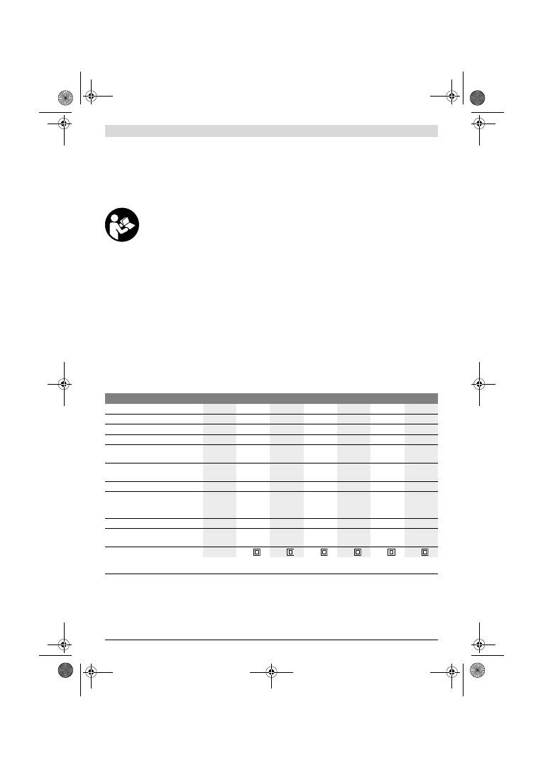
Dansk |
45
Bosch Power Tools
1 619 929 J37 | (2.2.12)
f
Hold altid maskinen fast med begge hænder og sørg for
at stå sikkert under arbejdet.
El-værktøjet føres sikkert
med to hænder.
f
Sikr emnet.
Et emne holdes bedre fast med spændean-
ordninger eller skruestik end med hånden.
Beskrivelse af produkt og ydelse
Læs alle sikkerhedsinstrukser og anvisnin-
ger.
I tilfælde af manglende overholdelse af
sikkerhedsinstrukserne og anvisningerne er
der risiko for elektrisk stød, brand og/eller al-
vorlige kvæstelser.
Klap venligst foldesiden med illustration af produktet ud og
lad denne side være foldet ud, mens du læser betjeningsvej-
ledningen.
Beregnet anvendelse
El-værktøjet er beregnet til tørslibning af træ, kunststof, spar-
telmasse og lakerede overflader.
Illustrerede komponenter
Nummereringen af de illustrerede komponenter refererer til
illustrationen af el-værktøjet på illustrationssiden.
1
Ekstrahåndtag (isoleret gribeflade)*
2
Skrue til ekstrahåndtag*
3
Hjul til indstilling af svingtal (GSS 230 AE/GSS 280 AE)
4
Start-stop-kontakt
5
Låsetast til start-stop-kontakt
6
Støvboks komplet (Microfilter System)*
7
Unbraconøglen
8
Klemmebøjle
9
Pudsesål
10
Klemmerække
11
Håndgreb (isoleret gribeflade)
12
Holder til støvboks*
13
Kunststofskyder
14
Udblæsningsstuds
15
Låsearm for støvboks*
16
Filterelement (Microfilter System)*
17
Opsugningsadapter*
18
Opsugningsslange*
19
Slibeblad*
20
Stanseværktøj*
21
Skruer til pudsesål
22
Pudsesål tynd, forlænget*
23
Slibeblad, forlænget*
24
Skruer til forlænget pudsesål*
25
Slibeblad, trekantet*
26
Pudsesål trekantet, forlænget*
*Tilbehør, som er illustreret og beskrevet i brugsanvisningen, er
ikke indeholdt i leveringen. Det fuldstændige tilbehør findes i vo-
res tilbehørsprogram.
Tekniske data
Støj-/vibrationsinformation
Måleværdier for støj beregnet iht. EN 60745.
Maskinens A-vægtede lydtrykniveau er typisk 76 dB(A). Usik-
kerhed K=3 dB.
Støvniveauet under arbejdet kan overskride 80 dB(A).
Brug høreværn!
Samlede vibrationsværdier a
h
(vektorsum for tre retninger)
og usikkerhed K beregnet iht. EN 60745:
a
h
=4,5 m/s
2
, K=1,5 m/s
2
.
Det svingningsniveau, der er angivet i nærværende instruk-
ser, er blevet målt iht. en standardiseret måleproces i
EN 60745, og kan bruges til at sammenligne el-værktøjer.
Rystepudser
GSS ...
230 A
230 AE
230 AE
280 A
280 AE
280 AE
Typenummer
0 601 ...
292 0..
292 7..
292 6..
293 0..
293 7..
293 6..
Støvboks følger med
–
–
z
–
–
z
Indstilling af svingningsantal
–
z
z
–
z
z
Nominel optagen effekt
W
300
300
300
330
330
330
Omdrejningstal, ubelastet
min
-1
11000
5500
– 11000
5500
– 11000
11000
5500
– 11000
5500
– 11000
Vibrationsfrekvens, ubelastet
min
-1
22000
11000
– 22000
11000
– 22000
22000
11000
– 22000
11000
– 22000
Svingkredsdiameter
mm
2,4
2,4
2,4
2,4
2,4
2,4
Slibebladmål
— Velcrolukning
— Klemmespænding
mm
mm
93 x 185
93 x 230
93 x 185
93 x 230
93 x 185
93 x 230
115 x 230
115 x 280
115 x 230
115 x 280
115 x 230
115 x 280
Mål pudsesål
mm
92 x 182
92 x 182
92 x 182 114 x 226 114 x 226 114 x 226
Vægt svarer til EPTA-Procedure
01/2003
kg
2,3
2,3
2,3
2,6
2,6
2,6
Beskyttelsesklasse
/
II
/
II
/
II
/
II
/
II
/
II
Angivelserne gælder for en nominel spænding [U] på 230 V. Disse angivelser kan variere ved afvigende spændinger og i landespecifikke udførelser.
Se typenummer på el-værktøjets typeskilt. Handelsbetegnelserne for de enkelte el-værktøjer kan variere.
OBJ_BUCH-426-005.book Page 45 Thursday, February 2, 2012 10:06 AM
46
| Dansk
1 619 929 J37 | (2.2.12)
Bosch Power Tools
Det er også egnet til en foreløbig vurdering af svingningsbe-
lastningen.
Det angivede svingningsniveau repræsenterer de væsentlige
anvendelser af el-værktøjet. Hvis el-værktøjet dog anvendes
til andre formål, med afvigende indsatsværktøj eller utilstræk-
kelig vedligeholdelse, kan svingningsniveauet afvige. Dette
kan føre til en betydelig forøgelse af svingningsbelastningen i
hele arbejdstidsrummet.
Til en nøjagtig vurdering af svingningsbelastningen bør der
også tages højde for de tider, i hvilke værktøjet er slukket eller
godt nok kører, men rent faktisk ikke anvendes. Dette kan fø-
re til en betydelig reduktion af svingningsbelastningen i hele
arbejdstidsrummet.
Fastlæg ekstra sikkerhedsforanstaltninger til beskyttelse af
brugeren mod svingningers virkning som f.eks.: Vedligehol-
delse af el-værktøj og indsatsværktøj, holde hænder varme,
organisation af arbejdsforløb.
Overensstemmelseserklæring
Vi erklærer under almindeligt ansvar, at det produkt, der er
beskrevet under „Tekniske data“, er i overensstemmelse med
følgende standarder eller normative dokumenter: EN 60745
iht. bestemmelserne i direktiverne 2011/65/EU,
2004/108/EF, 2006/42/EF.
Teknisk dossier (2006/42/EF) ved:
Robert Bosch GmbH, PT/ETM9,
D-70745 Leinfelden-Echterdingen
Robert Bosch GmbH, Power Tools Division
D-70745 Leinfelden-Echterdingen
12.01.2012
Montering
f
Træk stikket ud af stikkontakten, før der udføres arbej-
de på el-værktøjet.
Støv-/spånudsugning
f
Støv fra materialer som f.eks. blyholdig maling, nogle træ-
sorter, mineraler og metal kan være sundhedsfarlige. Be-
røring eller indånding af støv kan føre til allergiske reaktio-
ner og/eller åndedrætssygdomme hos brugeren eller
personer, der opholder sig i nærheden af arbejdspladsen.
Bestemt støv som f.eks. ege- eller bøgestøv gælder som
kræftfremkaldende, især i forbindelse med ekstra stoffer
til træbehandling (chromat, træbeskyttelsesmiddel). As-
bestholdigt materiale må kun bearbejdes af fagfolk.
– Brug helst en støvopsugning, der egner sig til materia-
let.
– Sørg for god udluftning af arbejdspladsen.
– Det anbefales at bære åndeværn med filterklasse P2.
Overhold forskrifterne, der gælder i dit land vedr. de mate-
rialer, der skal bearbejdes.
f
Undgå at der samler sig støv på arbejdspladsen.
Støv
kan let antænde sig selv.
Egenopsugning med støvboks (se Fig. A1 – A4)
Træk kunststofskyderen
13
ud, før støvboksen monteres
6
.
Anbring støvboksen
6
på udsblæsningsstudsen
14
, til den fal-
der på plads. Sørg for, at kunststofskyderen
13
griber ind i
holderen
12
.
Til tømning af støvboksen
6
trykkes på låsearmen
15
på siden
af støvboksen (
n
). Træk støvboksen af nedad (
o
).
Før åbning af støvboksen
6
bør støvboksen bankes mod et
fast underlag som vist på billedet, så støvet kan løsne sig fra
filterelementet.
Tag fat i støvboksen
6
i grebet, klap filterelementet
16
væk
opadtil og tøm støvboksen. Rengør lamellerne på filterele-
mentet
16
med en blød børste.
Opsugning med fremmed støvsuger (se Fig. B)
Sæt opsugningsadapteren
17
på udblæsningsstudsen
14
.
Sørg for at opsugningsadapterens låsearm falder rigtigt i hak.
Til opsugningsadapteren
17
kan der tilsluttes en opsugnings-
slange med en diameter på 19 mm.
Opsugningsadapteren
17
demonteres ved at trykke den ba-
geste del af dennes låsearm sammen og fjerne opsugningsa-
dapteren.
Støvsugeren skal være egnet til det materiale, som skal opsu-
ges.
Anvend en specialstøvsuger til opsugning af særligt sund-
hedsfarligt, kræftfremkaldende eller tørt støv.
Udskiftning af slibeblad
Fjern snavs og støv fra pudsesålen
9
f.eks. med en pensel, før
et nyt slibeblad sættes på.
En optimal støvopsugning forudsætter, at udstansningerne i
slibebladet passer til boringerne i pudsesålen.
Slibeblade med velcrolukning (se Fig. C)
Pudsesålen
9
er udstyret med velcrostof, hvilket gør det hur-
tigt og nemt at fastgøre slibeblade med velcrolukning.
Bank på pudsesålens
9
velcrostof før slibebladet
19
sættes
på for at sikre en optimal vedhæftning.
Anbring slibebladet
19
langs med den ene side af pudsesålen
9
, læg herefter slibebladet på pudsesålen og tryk det godt
fast.
Til aftagning af slibebladet
19
tages fat i en spids, hvorefter
det trækkes af pudsesålen
9
.
Slibeblade uden velcrolukning (se Fig. D)
Løft klemmebøjlen
8
en smule og tag den af.
Før slibebladet
19
helt ind under den åbnede, bageste klem-
mebjælke
10
og spænd slibebladet ved at fastgøre klemme-
bøjlen
8
.
Læg slibebladet
19
stramt omkring pudsesålen. Før den an-
den ende af slibebladet
19
ind under den åbnede, forreste
klemmebjælke
10
og spænd slibebladet ved at fastgøre klem-
mebøjlen
8
.
Uhullede slibeblade, f.eks. rulle- eller metervare, kan hulles til
støvopsugning med stanseværktøjet
20
. Tryk el-værktøjet
med monteret slibeblad på stanseværktøjet (se billede E).
Slibebladet
19
tages af ved at løsne klemmebøjlen
8
og træk-
ke slibebladet ud.
Dr. Egbert Schneider
Senior Vice President
Engineering
Dr. Eckerhard Strötgen
Engineering Director
PT/ESI
OBJ_BUCH-426-005.book Page 46 Thursday, February 2, 2012 10:06 AM
Dansk |
47
Bosch Power Tools
1 619 929 J37 | (2.2.12)
Valg af slibeblad
Vælg det slibeblad og den afslibningsmåde, som passer bedst
til det materiale, som skal bearbejdes:
Udskiftning af slibeblad (se Fig. F)
Pudsesålen
9
kan skiftes efter behov.
Drej de 6 skruer
21
helt ud og tag pudsesålen
9
af. Sæt den
nye pudsesål
9
på og spænd skruerne fast igen.
Specielle pudsesåle
Du kan erstatte den medleverede pudsesål
9
med en speciel
pudsesål, som fås som tilbehør.
Den specielle pudsesål monteres lige som den medleverede
pudsesål skiftes.
Den pågældende pudsesål sættes på og tages af lige som det
originale slibeblad skiftes.
Forlænget pudsesål, firkantet, tynd
(GSS 230 A/GSS 230 AE) (se Fig. G)
Den firkantede, tynde, forlængede pudsesål
22
benyttes til at
slibe på vanskeligt tilgængelige steder og smalle mellemrum
som f. eks. vindues- og dørlameller, noter eller bag ved radia-
tor- og vandrør.
Til montering af den retvinklede, tynde, forlængede pudsesål
22
anvendes de tilhørende skruer
24
.
Forlænget pudsesål, trekantet
(GSS 230 A/GSS 230 AE) (se Fig. H)
Med den trekantede, forlængede pudsesål
26
kan man slibe
hjørner og kanter.
Fin pudsesål (uden velcrolukning)
(GSS 230 AE/GSS 280 AE) (se Fig. D)
Hvis man især benytter standardslibeblade uden velcroluk-
ning anbefales det at benytte en fin pudsesål uden velcroluk-
ning. Pudsesålens plane overflade gør det muligt at opnå op-
timale sliberesultater, især ved finslibning.
Ekstrahåndtag
Ekstrahåndtaget
1
sikrer en behagelig håndtering og optimal
kraftfordeling, især ved stor afslibning.
Fastgør ekstrahåndtaget
1
på huset med skruen
2
.
Brug
Ibrugtagning
f
Kontrollér netspændingen! Strømkildens spænding
skal stemme overens med angivelserne på el-værktø-
jets typeskilt. El-værktøj til 230 V kan også tilsluttes
220 V.
Tænd/sluk
Til
ibrugtagning
af el-værktøjet tryk på start-stop-kontakten
4
og hold den nede.
Til
fastlåsning
af den nedtrykkede start-stop-kontakt
4
tryk-
kes på låsetasten
5
.
El-værktøjet
slukkes
ved at slippe start-stop-kontakten
4
er
den låst med låsetasten
5
trykkes kort på start-stop-kontak-
ten
4
hvorefter den slippes.
Indstilling af svingtal (GSS 230 AE/GSS 280 AE)
Med stillehjulet indstilling af svingtal
3
kan du indstille det
nødvendige svingtal under driften.
Det krævede svingtal afhænger af arbejdsmaterialet og ar-
bejdsbetingelserne; det fastlægges bedst ved praktiske for-
søg.
Arbejdsvejledning
f
El-værktøjet må først lægges fra, når det står helt
stille.
Slibekapaciteten under slibearbejdet bestemmes hovedsage-
ligt af det valgte slibeblad samt af det valgte svingtal
(GSS 230 AE/GSS 280 AE).
Kun fejlfrie slibeblade sikrer et godt sliberesultat og skåner
el-værktøjet.
Sørg for jævnt slibetryk, da dette er med til at forlænge slibe-
bladenes levetid.
Et overdrevet tryk fører ikke til en større slibekapacitet, men
derimod til et større slid af el-værktøj og slibepapir.
Anvend ikke et slibeblad, der forinden har været brug til slib-
ning af metal, til andre materialer.
Anvend kun originalt Bosch slibetilbehør.
Vedligeholdelse og service
Vedligeholdelse og rengøring
f
Træk stikket ud af stikkontakten, før der udføres arbej-
de på el-værktøjet.
f
El-værktøj og el-værktøjets ventilationsåbninger skal
altid holdes rene for at sikre et godt og sikkert arbejde.
Hvis det er nødvendigt at erstatte tilslutningsledningen, skal
dette arbejde udføres af Bosch eller på et autoriseret service-
værksted for Bosch el-værktøj for at undgå farer.
Korn
40–400
Til alle træsorter
Til forslibning f.eks. af ru, uhøvle-
de bjælker og brædder
grov
40, 60
Til planslibning og udjævning af
små ujævnheder
middel 80, 100, 120
Til færdig- og finslibning af hårdt
træ
fin
180, 240,
320, 400
40–320
Til bearbejdning af farve-/lak-
lag og grundinger som f.eks.
fyldstof og spartelmasse
Til afslibning af farve
grov
40, 60
Til slibning af grundering
middel 80, 100, 120
Til endelig slibning af grundering
før lakering
fin
180, 240, 320
OBJ_BUCH-426-005.book Page 47 Thursday, February 2, 2012 10:06 AM
48
| Svenska
1 619 929 J37 | (2.2.12)
Bosch Power Tools
Skulle el-værktøjet trods omhyggelig fabrikation og kontrol
holde op med at fungere, skal reparationen udføres af et auto-
riseret serviceværksted for Bosch-elektroværktøj.
El-værktøjets 10-cifrede typenummer (se typeskilt) skal altid
angives ved forespørgsler og bestilling af reservedele.
Kundeservice og kunderådgivning
Kundeservice besvarer dine spørgsmål vedr. reparation og
vedligeholdelse af dit produkt samt reservedele. Reservedel-
stegninger og informationer om reservedele findes også un-
der:
www.bosch-pt.com
Bosch kundeservice-team vil gerne hjælpe dig med at besvare
spørgsmål vedr. køb, anvendelse og indstilling af produkter
og tilbehør.
Dansk
Bosch Service Center
Telegrafvej 3
2750 Ballerup
Tlf. Service Center: +45 (4489) 8855
Fax: +45 (4489) 87 55
E-Mail: vaerktoej@dk.bosch.com
Bortskaffelse
El-værktøj, tilbehør og emballage skal genbruges på en miljø-
venlig måde.
Smid ikke el-værktøj ud sammen med det almindelige hus-
holdningsaffald!
Gælder kun i EU-lande:
Iht. det europæiske direktiv 2002/96/EF
om affald af elektrisk og elektronisk udstyr
skal kasseret elektrisk udstyr indsamles se-
parat og genbruges iht. gældende miljøfor-
skrifter.
Ret til ændringer forbeholdes.
Svenska
Säkerhetsanvisningar
Allmänna säkerhetsanvisningar för elverktyg
Läs noga igenom alla säkerhetsanvis-
ningar och instruktioner.
Fel som upp-
står till följd av att säkerhetsanvisningarna och instruktio-
nerna inte följts kan orsaka elstöt, brand och/eller allvarliga
personskador.
Förvara alla varningar och anvisningar för framtida bruk.
Nedan använt begrepp ”Elverktyg” hänför sig till nätdrivna
elverktyg (med nätsladd) och till batteridrivna elverktyg
(sladdlösa).
Arbetsplatssäkerhet
f
Håll arbetsplatsen ren och välbelyst.
Oordning på
arbetsplatsen och dåligt belyst arbetsområde kan leda till
olyckor.
f
Använd inte elverktyget i explosionsfarlig omgivning
med brännbara vätskor, gaser eller damm.
Elverktygen
alstrar gnistor som kan antända dammet eller gaserna.
f
Håll under arbetet med elverktyget barn och obehöriga
personer på betryggande avstånd.
Om du störs av obe-
höriga personer kan du förlora kontrollen över elverktyget.
Elektrisk säkerhet
f
Elverktygets stickpropp måste passa till vägguttaget.
Stickproppen får absolut inte förändras. Använd inte
adapterkontakter tillsammans med skyddsjordade
elverktyg.
Oförändrade stickproppar och passande vägg-
uttag reducerar risken för elstöt.
f
Undvik kroppskontakt med jordade ytor som t. ex. rör,
värmeelement, spisar och kylskåp.
Det finns en större
risk för elstöt om din kropp är jordad.
f
Skydda elverktyget mot regn och väta.
Tränger vatten in
i ett elverktyg ökar risken för elstöt.
f
Missbruka inte nätsladden och använd den inte för att
bära eller hänga upp elverktyget och inte heller för att
dra stickproppen ur vägguttaget. Håll nätsladden på
avstånd från värme, olja, skarpa kanter och rörliga
maskindelar.
Skadade eller tilltrasslade ledningar ökar
risken för elstöt.
f
När du arbetar med ett elverktyg utomhus använd
endast förlängningssladdar som är avsedda för utom-
husbruk.
Om en lämplig förlängningssladd för utomhus-
bruk används minskar risken för elstöt.
f
Använd ett felströmsskydd om det inte är möjligt att
undvika elverktygets användning i fuktig miljö.
Fel-
strömsskyddet minskar risken för elstöt.
Personsäkerhet
f
Var uppmärksam, kontrollera vad du gör och använd
elverktyget med förnuft. Använd inte elverktyg när du
är trött eller om du är påverkad av droger, alkohol eller
mediciner.
Under användning av elverktyg kan även en
kort ouppmärksamhet leda till allvarliga kroppsskador.
f
Bär alltid personlig skyddsutrustning och skyddsglas-
ögon.
Användning av personlig skyddsutrustning som
t.ex. dammfiltermask, halkfria säkerhetsskor, skydds-
hjälm och hörselskydd reducerar alltefter elverktygets typ
och användning risken för kroppsskada.
f
Undvik oavsiktlig igångsättning. Kontrollera att elverk-
tyget är frånkopplat innan du ansluter stickproppen till
vägguttaget och/eller ansluter/tar bort batteriet, tar
upp eller bär elverktyget.
Om du bär elverktyget med
fingret på strömställaren eller ansluter påkopplat elverktyg
till nätströmmen kan olycka uppstå.
f
Ta bort alla inställningsverktyg och skruvnycklar innan
du kopplar på elverktyget.
Ett verktyg eller en nyckel i en
roterande komponent kan medföra kroppsskada.
VARNING
OBJ_BUCH-426-005.book Page 48 Thursday, February 2, 2012 10:06 AM
Svenska |
49
Bosch Power Tools
1 619 929 J37 | (2.2.12)
f
Undvik onormala kroppsställningar. Se till att du står
stadigt och håller balansen.
I detta fall kan du lättare kon-
trollera elverktyget i oväntade situationer.
f
Bär lämpliga arbetskläder. Bär inte löst hängande klä-
der eller smycken. Håll håret, kläderna och handskarna
på avstånd från rörliga delar.
Löst hängande kläder,
långt hår och smycken kan dras in av roterande delar.
f
När elverktyg används med dammutsugnings- och
-uppsamlingsutrustning, se till att dessa är rätt monte-
rade och används på korrekt sätt.
Användning av damm-
utsugning minskar de risker damm orsakar.
Korrekt användning och hantering av elverktyg
f
Överbelasta inte elverktyget. Använd för aktuellt
arbete avsett elverktyg.
Med ett lämpligt elverktyg kan
du arbeta bättre och säkrare inom angivet effektområde.
f
Ett elverktyg med defekt strömställare får inte längre
användas.
Ett elverktyg som inte kan kopplas in eller ur är
farligt och måste repareras.
f
Dra stickproppen ur vägguttaget och/eller ta bort bat-
teriet innan inställningar utförs, tillbehörsdelar byts ut
eller elverktyget lagras.
Denna skyddsåtgärd förhindrar
oavsiktlig inkoppling av elverktyget.
f
Förvara elverktygen oåtkomliga för barn. Låt elverkty-
get inte användas av personer som inte är förtrogna
med dess användning eller inte läst denna anvisning.
Elverktygen är farliga om de används av oerfarna personer.
f
Sköt elverktyget omsorgsfullt. Kontrollera att rörliga
komponenter fungerar felfritt och inte kärvar, att kom-
ponenter inte brustit eller skadats; orsaker som kan
leda till att elverktygets funktioner påverkas menligt.
Låt skadade delar repareras innan elverktyget tas i
bruk.
Många olyckor orsakas av dåligt skötta elverktyg.
f
Håll skärverktygen skarpa och rena.
Omsorgsfullt skötta
skärverktyg med skarpa eggar kommer inte så lätt i kläm
och går lättare att styra.
f
Använd elverktyget, tillbehör, insatsverktyg osv.
enligt dessa anvisningar. Ta hänsyn till arbetsvillkoren
och arbetsmomenten.
Om elverktyget används på ett sätt
som det inte är avsett för kan farliga situationer uppstå.
Service
f
Låt endast kvalificerad fackpersonal reparera elverk-
tyget och endast med originalreservdelar.
Detta garan-
terar att elverktygets säkerhet upprätthålls.
Säkerhetsanvisningar för slipmaskiner
f
Använd elverktyget endast för torrslipning.
Tränger
vatten in i ett elverktyg ökar risken för elstöt.
f
Observera brandrisk! Undvika att överhetta slipytan
och slipmaskinen. Töm dammbehållaren före arbets-
pauser.
Slipdammet i dammpåsen, mikrofiltret, pappers-
påsen (eller i filterpåsen resp. dammsugarens filter) kan
under ogynnsamma förhållanden antändas av t. ex. gnistor
som bildas vid slipning av metall. Särskilt farligt är ett slip-
damm som innehåller lack-, uratanrester eller andra
kemiska ämnen som kan antändas när arbetsstycket efter
en längre tids arbete blir hett.
f
Håll i elverktyget med båda händerna under arbetet
och se till att du står stadigt.
Elverktyget kan styras säk-
rare med två händer.
f
Säkra arbetsstycket.
Ett arbetsstycke som är fastspänt i
en uppspänningsanordning eller ett skruvstycke hålls säk-
rare än med handen.
Produkt- och kapacitetsbeskrivning
Läs noga igenom alla säkerhetsanvis-
ningar och instruktioner.
Fel som uppstår
till följd av att säkerhetsanvisningarna och
instruktionerna inte följts kan orsaka elstöt,
brand och/eller allvarliga personskador.
Fäll upp sidan med illustration av elverktyget och håll sidan
uppfälld när du läser bruksanvisningen.
Ändamålsenlig användning
Elverktyget är avsett för torrslipning av trä, plast, spackel-
massa samt lackerade ytor.
Illustrerade komponenter
Numreringen av komponenterna hänvisar till illustration av
elverktyget på grafiksida.
1
Stödhandtag (isolerad greppyta)*
2
Skruv för stödhandtag*
3
Ställratt slagtalsförval (GSS 230 AE/GSS 280 AE)
4
Strömställare Till/Från
5
Spärrknapp för strömställaren
6
Filterbox komplett (Microfilter System)*
7
Sexkantnyckel
8
Klämbygel
9
Slipplatta
10
Klämskena
11
Handgrepp (isolerad greppyta)
12
Fäste för dammbox*
13
Plastslid
14
Utblåsningsstuts
15
Låsarm för filterbox*
16
Filterelement (Microfilter System)*
17
Utsugningsadapter*
18
Utsugningsslang*
19
Slippapper*
20
Stansverktyg*
21
Skruvar för slipplatta
22
Slipplatta tunn, förlängd*
23
Slippapper, förlängt*
24
Skruv för förlängd slipplatta*
25
Slippapper, i triangelform*
26
Slipplatta i triangelform, förlängd*
*I bruksanvisningen avbildat och beskrivet tillbehör ingår inte i
standardleveransen. I vårt tillbehörsprogram beskrivs allt tillbe-
hör som finns.
OBJ_BUCH-426-005.book Page 49 Thursday, February 2, 2012 10:06 AM

50
| Svenska
1 619 929 J37 | (2.2.12)
Bosch Power Tools
Tekniska data
Buller-/vibrationsdata
Mätvärdena för ljudnivån anges enligt EN 60745.
Elverktygets A-vägda ljudtrycksnivå når i typiska fall
76 dB(A). Onoggrannhet K=3 dB.
Ljudnivån under arbetet kan överskrida 80 dB(A).
Använd hörselskydd!
Totala vibrationsemissionsvärden a
h
(vektorsumma ur tre
riktningar) och onoggrannhet K framtaget enligt EN 60745:
a
h
=4,5 m/s
2
, K=1,5 m/s
2
.
Mätningen av den vibrationsnivå som anges i denna anvisning
har utförts enligt en mätmetod som är standardiserad i
EN 60745 och kan användas vid jämförelse av olika elverk-
tyg. Mätmetoden är även lämplig för preliminär bedömning av
vibrationsbelastningen.
Den angivna vibrationsnivån representerar den huvudsakliga
användningen av elverktyget. Om däremot elverktyget
används för andra ändamål och med andra insatsverktyg eller
inte underhållits ordentligt kan vibrationsnivån avvika. Härvid
kan vibrationsbelastningen under arbetsperioden öka betyd-
ligt.
För en exakt bedömning av vibrationsbelastningen bör även
de tider beaktas när elverktyget är frånkopplat eller är igång,
men inte används. Detta reducerar tydligt vibrationsbelast-
ningen för den totala arbetsperioden.
Bestäm extra säkerhetsåtgärder för att skydda operatören
mot vibrationernas inverkan t. ex.: underhåll av elverktyget
och insatsverktygen, att hålla händerna varma, organisation
av arbetsförloppen.
Försäkran om överensstämmelse
Vi försäkrar härmed under exklusivt ansvar att denna produkt
som beskrivs i ”Tekniska data” överensstämmer med följande
normer och normativa dokument: EN 60745 enligt bestäm-
melserna i direktiven 2011/65/EU, 2004/108/EG,
2006/42/EG.
Teknisk tillverkningsdokumentation (2006/42/EG) fås från:
Robert Bosch GmbH, PT/ETM9,
D-70745 Leinfelden-Echterdingen
Robert Bosch GmbH, Power Tools Division
D-70745 Leinfelden-Echterdingen
12.01.2012
Montage
f
Dra stickproppen ur nätuttaget innan arbeten utförs på
elverktyget.
Damm-/spånutsugning
f
Dammet från material som t. ex. blyhaltig målning, vissa
träslag, mineraler och metall kan vara hälsovådligt. Berö-
ring eller inandning av dammet kan orsaka allergiska reak-
tioner och/eller andningsbesvär hos användaren eller per-
soner som uppehåller sig i närheten.
Vissa damm från ek eller bok anses vara cancerogena, spe-
ciellt då i förbindelse med tillsatsämnen för träbehandling
(kromat, träkonserveringsmedel). Endast yrkesmän får
bearbeta asbesthaltigt material.
– Använd om möjligt en för materialet lämplig dammut-
sugning.
– Se till att arbetsplatsen är väl ventilerad.
– Vi rekommenderar ett andningsskydd i filterklass P2.
Beakta de föreskrifter som i aktuellt land gäller för bearbe-
tat material.
f
Undvik dammanhopning på arbetsplatsen.
Damm kan
lätt självantändas.
Planslip
GSS ...
230 A
230 AE
230 AE
280 A
280 AE
280 AE
Produktnummer
0 601 ...
292 0..
292 7..
292 6..
293 0..
293 7..
293 6..
Dammbox ingår i leveransen
–
–
z
–
–
z
Förval av svängningstal
–
z
z
–
z
z
Upptagen märkeffekt
W
300
300
300
330
330
330
Tomgångsvarvtal
min
-1
11000
5500
– 11000
5500
– 11000
11000
5500
– 11000
5500
– 11000
Svängningstal obelastad
min
-1
22000
11000
– 22000
11000
– 22000
22000
11000
– 22000
11000
– 22000
Sliprörelsens diameter
mm
2,4
2,4
2,4
2,4
2,4
2,4
Slippapperdimensioner
— Kardborrfäste
— Klämspänning
mm
mm
93 x 185
93 x 230
93 x 185
93 x 230
93 x 185
93 x 230
115 x 230
115 x 280
115 x 230
115 x 280
115 x 230
115 x 280
Slipplattans dimensioner
mm
92 x 182
92 x 182
92 x 182 114 x 226 114 x 226 114 x 226
Vikt enligt EPTA-Procedure
01/2003
kg
2,3
2,3
2,3
2,6
2,6
2,6
Skyddsklass
/
II
/
II
/
II
/
II
/
II
/
II
Uppgifterna gäller för en märkspänning på [U] 230 V. Vid avvikande spänning och för utföranden i vissa länder kan uppgifterna variera.
Beakta produktnumret på elverktygets typskylt. Handelsbeteckningarna för enskilda elverktyg kan variera.
Dr. Egbert Schneider
Senior Vice President
Engineering
Dr. Eckerhard Strötgen
Engineering Director
PT/ESI
OBJ_BUCH-426-005.book Page 50 Thursday, February 2, 2012 10:06 AM
Svenska |
51
Bosch Power Tools
1 619 929 J37 | (2.2.12)
Självutsugning med filterbox (se bild A1 – A4)
Dra före montering av dammboxen
6
ut plastsliden
13
. Skjut
upp dammboxen
6
på utblåsningsstutsen
14
tills den snäpper
fast. Se till att plastsliden
13
griper in i fästet
12
.
För tömning av filterboxen
6
tryck ned låsarmen
15
på sidan
om filterboxen (
n
). Dra bort filterboxen nedåt (
o
).
Innan filterboxen
6
öppnas knacka boxen mot ett fast under-
lag som bilden visar för att lösa dammet ur filterelementet.
Grip tag i filterboxen
6
i greppfördjupningen, fäll filter-
elementet
16
uppåt och töm filterboxen. Rena filter-
elementets lameller
16
med en mjuk borste.
Extern utsugning (se bild B)
Skjut upp utsugningsadaptern
17
på utblåsningsstutsen
14
.
Kontrollera att utsugningsadapterns låsarmar snäpper fast.
Till utsugningsadaptern
17
kan en utsugningsslang med en
diameter på 19 mm anslutas.
För borttagning av utsugningsadaptern
17
tryck baktill ihop
låsarmarna och dra av utsugningsadaptern.
Dammsugaren måste vara lämplig för det material som ska
bearbetas.
Använd för utsugning av hälsovådligt och cancerframkallande
eller torrt damm en specialdammsugare.
Byte av slippapper
Innan ett nytt slippapper läggs upp ska smuts och damm
avlägsnas från slipplattan
9
, t. ex. med en pensel.
För att optimal dammutsugning ska kunna garanteras måste
slippapperets hål överensstämma med slipplattans.
Slippapper med kardborrfäste (se bild C)
Slipplattan
9
är försedd med en kardborrsväv för snabb och
enkel infästning av slippapperen med kardborrssystem.
Knacka slipplattans
9
kardborrsväv ren innan slippapperet
19
sätts på för att uppnå optimal infästning.
Lägg upp slippapperet
19
kant i kant med en sida på slipplat-
tan
9
, tryck sedan kraftigt fast slippapperet på slipplattan.
För borttagning av slippapperet
19
grip tag i ett hör och dra av
papperet från slipplattan
9
.
Slippapper utan kardborrfäste (se bild D)
Lyft lätt upp klämbygeln
8
och häng av den.
För in slippapperet
19
mot anslaget under den öppna bakre
klämskenan
10
och spänn fast slippapperet genom att hänga
upp spännbygeln
8
.
Lägg upp slippapperet
19
stramt kring slipplattan. För in slip-
papperets
19
andra ända under den öppna främre
klämskenan
10
och spänn fast slippapperet genom att hänga
upp spännbygeln
8
.
Ohålade slippapper t. ex. från rulle eller metervara kan för
dammutsugning hålas med stansverktyget
20
. För håltagning
tryck elverktyget med monterat slippapper mot stansverkty-
get (se bild E).
För borttagning av slippapperet
19
lossa klämbygeln
8
och
dra ut slippapperet.
Val av slippapper
Slippapper finns att tillgå i olika utföranden som motsvarar
material som ska bearbetas och önskad nedslipningseffekt:
Byte av slipplatta (se bild F)
Slipplattan
9
kan vid behov bytas ut.
Skruva bort de 6 skruvarna
21
och ta bort slipplattan
9
. Lägg
upp den nya slipplattan
9
och dra fast skruvarna.
Specialslipplattor
Den medlevererade slipplattan
9
kan vid behov bytas mot en
specialslipplatta som finns att köpa som tillbehör.
Specialslipplattan monteras på samma sätt som medlevere-
rad slipplatta.
Påsättning och borttagning av slippapperet sker på samma
sätt som vid byte av originalslippapper.
Förlängd slipplatta, rektangulär, tunn
(GSS 230 A/GSS 230 AE) (se bild G)
Med den rektangulära, tunna och förlängda slipplattan
22
kan
slipning utföras på svåråtkomliga ställen och i smala springor
exempelvis mellan fönster- och dörrlameller, i spår och
bakom värmeelements- och vattenrör.
Använd för montering av den rektangulära, tunna, förlängda
slipplattan
22
tillhörande skruvar
24
.
Förlängd slipplatta, i triangelform
(GSS 230 A/GSS 230 AE) (se bild H)
Med den förlängda slipplattan
26
i triangelform kan slipning
ske i hörn och kanter.
Finslipplatta (utan kardborrfäste)
(GSS 230 AE/GSS 280 AE) (se bild D)
När huvudsakligen standardslippapper utan kardborrinfäst-
ning används, rekommenderas finslipplattor utan kardborr-
fäste. Tack vare slipplattans plana yta uppnås vid finslipning
optimala slipresultat.
Kornstorlek
40–400
För bearbetning av alla träslag
För förslipning t. ex. av råa, ohyv-
lade bjälkar och brädor
grov
40, 60
För planslipning och planing av
mindre ojämnheter
medel-
grov
80, 100, 120
För färdig- och finslipning av hårt
trä
fin
180, 240,
320, 400
40–320
För slipning av färg-/lackskikt
resp. grundning som filler och
spackel
För nedslipning av färg
grov
40, 60
För slipning av grundfärg
medel-
grov
80, 100, 120
För slipning av mellanstryknings-
färg före lackering
fin
180, 240, 320
OBJ_BUCH-426-005.book Page 51 Thursday, February 2, 2012 10:06 AM
52
| Norsk
1 619 929 J37 | (2.2.12)
Bosch Power Tools
Stödhandtag
Stödhandtaget
1
medger en bekväm hantering och en optimal
kraftfördelning speciellt vid djup nedslipning.
Skruva fast stödhandtaget
1
på motorhuset med skruven
2
.
Drift
Driftstart
f
Beakta nätspänningen! Kontrollera att strömkällans
spänning överensstämmer med uppgifterna på elverk-
tygets typskylt. Elverktyg märkta med 230 V kan även
anslutas till 220 V.
In- och urkoppling
Tryck för
start
av elverktyget ned strömställaren Till/Från
4
och håll den nedtryckt.
För att
spärra
den nedtryckta strömställaren Till/Från
4
tryck
ned spärrknappen
5
.
För elverktygets
frånkoppling
släpp strömställaren Till/Från
4
eller om den är låst med spärrknappen
5
tryck helt kort på
strömställaren Till/Från
4
och släpp den igen.
Förval av svängningstal (GSS 230 AE/GSS 280 AE)
Med ställratten för förval av svängningstal
3
kan önskat sväng-
ningstal väljas även under drift.
Erforderligt svängningstal är beroende av material och
arbetsbetingelser, prova dig fram till bästa inställning genom
praktiska försök.
Arbetsanvisningar
f
Vänta tills elverktyget stannat helt innan du lägger bort
det.
Avverkningseffekten vid slipning är främst beroende av att
rätt slippapper valts och lämpligt svängningstal förinställts
(GSS 230 AE/GSS 280 AE).
Endast felfria slippapper ger gott slipresultat samtidigt som
de skonar elverktyget.
Slippapperen kan användas under en längre tid om slipning
sker med jämnt anliggningstryck.
Ett kraftigt ökat anliggningstryck medför inte en högre slipef-
fekt, utan kraftigare förslitning på elverktyg och slippapper.
Slippapper som använts för slipning av metall får inte längre
användas för andra material.
Använd endast original Bosch sliptillbehör.
Underhåll och service
Underhåll och rengöring
f
Dra stickproppen ur nätuttaget innan arbeten utförs på
elverktyget.
f
Håll elverktyget och dess ventilationsöppningar rena
för bra och säkert arbete.
Om nätsladden för bibehållande av verktygets säkerhet
måste bytas ut, ska byte ske hos Bosch eller en auktoriserad
serviceverkstad för Bosch-elverktyg.
Om i elverktyget trots exakt tillverkning och sträng kontroll
störning skulle uppstå, bör reparation utföras av auktoriserad
serviceverkstad för Bosch elverktyg.
Ange alltid vid förfrågningar och reservdelsbeställningar det
10-siffriga produktnumret som finns på elverktygets typskylt.
Kundservice och kundkonsulter
Kundservicen ger svar på frågor beträffande reparation och
underhåll av produkter och reservdelar. Sprängskissar och
informationer om reservdelar lämnas även på adressen:
www.bosch-pt.com
Bosch kundkonsultgruppen hjälper gärna när det gäller frågor
beträffande köp, användning och inställning av produkter och
tillbehör.
Svenska
Bosch Service Center
Telegrafvej 3
2750 Ballerup
Danmark
Tel.: +46 (020) 41 44 55
Fax: +46 (011) 18 76 91
Avfallshantering
Elverktyg, tillbehör och förpackning ska omhändertas på
miljövänligt sätt för återvinning.
Släng inte elverktyg i hushållsavfall!
Endast för EU-länder:
Enligt europeiska direktivet 2002/96/EG
för kasserade elektriska och elektroniska
apparater och dess modifiering till nationell
rätt måste obrukbara elverktyg omhänder-
tas separat och på miljövänligt sätt lämnas
in för återvinning.
Ändringar förbehålles.
Norsk
Sikkerhetsinformasjon
Generelle advarsler for elektroverktøy
Les gjennom alle advarslene og anvis-
ningene.
Feil ved overholdelsen av ad-
varslene og nedenstående anvisninger kan medføre elektris-
ke støt, brann og/eller alvorlige skader.
Ta godt vare på alle advarslene og informasjonene.
Det nedenstående anvendte uttrykket «elektroverktøy» gjel-
der for strømdrevne elektroverktøy (med ledning) og batteri-
drevne elektroverktøy (uten ledning).
Sikkerhet på arbeidsplassen
f
Hold arbeidsområdet rent og ryddig og sørg for bra be-
lysning.
Rotete arbeidsområder eller arbeidsområder
uten lys kan føre til ulykker.
ADVARSEL
OBJ_BUCH-426-005.book Page 52 Thursday, February 2, 2012 10:06 AM

Norsk |
53
Bosch Power Tools
1 619 929 J37 | (2.2.12)
f
Ikke arbeid med elektroverktøyet i eksplosjonsutsatte
omgivelser – der det befinner seg brennbare væsker,
gass eller støv.
Elektroverktøy lager gnister som kan an-
tenne støv eller damper.
f
Hold barn og andre personer unna når elektroverktøy-
et brukes.
Hvis du blir forstyrret under arbeidet, kan du
miste kontrollen over elektroverktøyet.
Elektrisk sikkerhet
f
Støpselet til elektroverktøyet må passe inn i stikkon-
takten. Støpselet må ikke forandres på noen som helst
måte. Ikke bruk adapterstøpsler sammen med jordede
elektroverktøy.
Bruk av støpsler som ikke er forandret på
og passende stikkontakter reduserer risikoen for elektris-
ke støt.
f
Unngå kroppskontakt med jordede overflater slik som
rør, ovner, komfyrer og kjøleskap.
Det er større fare ved
elektriske støt hvis kroppen din er jordet.
f
Hold elektroverktøyet unna regn eller fuktighet.
Der-
som det kommer vann i et elektroverktøy, øker risikoen for
elektriske støt.
f
Ikke bruk ledningen til andre formål, f. eks. til å bære
elektroverktøyet, henge det opp eller trekke det ut av
stikkontakten. Hold ledningen unna varme, olje, skar-
pe kanter eller verktøydeler som beveger seg.
Med ska-
dede eller opphopede ledninger øker risikoen for elektris-
ke støt.
f
Når du arbeider utendørs med et elektroverktøy, må du
kun bruke en skjøteledning som er egnet til utendørs
bruk.
Når du bruker en skjøteledning som er egnet for
utendørs bruk, reduseres risikoen for elektriske støt.
f
Hvis det ikke kan unngås å bruke elektroverktøyet i
fuktige omgivelser, må du bruke en jordfeilbryter.
Bruk
av en jordfeilbryter reduserer risikoen for elektriske støt.
Personsikkerhet
f
Vær oppmerksom, pass på hva du gjør, gå fornuftig
frem når du arbeider med et elektroverktøy. Ikke bruk
elektroverktøy når du er trett eller er påvirket av nar-
kotika, alkohol eller medikamenter.
Et øyeblikks uopp-
merksomhet ved bruk av elektroverktøyet kan føre til al-
vorlige skader.
f
Bruk personlig verneutstyr og husk alltid å bruke ver-
nebriller.
Bruk av personlig sikkerhetsutstyr som støv-
maske, sklifaste arbeidssko, hjelm eller hørselvern – av-
hengig av type og bruk av elektroverktøyet – reduserer
risikoen for skader.
f
Unngå å starte verktøyet ved en feiltagelse. Forviss
deg om at elektroverktøyet er slått av før du kobler det
til strømmen og/eller batteriet, løfter det opp eller bæ-
rer det.
Hvis du holder fingeren på bryteren når du bærer
elektroverktøyet eller kobler elektroverktøyet til strøm-
men i innkoblet tilstand, kan dette føre til uhell.
f
Fjern innstillingsverktøy eller skrunøkler før du slår på
elektroverktøyet.
Et verktøy eller en nøkkel som befinner
seg i en roterende verktøydel, kan føre til skader.
f
Unngå en unormal kroppsholdning. Sørg for å stå stø-
dig og i balanse.
Dermed kan du kontrollere elektroverk-
tøyet bedre i uventede situasjoner.
f
Bruk alltid egnede klær. Ikke bruk vide klær eller smyk-
ker. Hold hår, tøy og hansker unna deler som beveger
seg.
Løstsittende tøy, smykker eller langt hår kan komme
inn i deler som beveger seg.
f
Hvis det kan monteres støvavsug- og oppsamlingsinn-
retninger, må du forvisse deg om at disse er tilkoblet og
brukes på korrekt måte.
Bruk av et støvavsug reduserer
farer på grunn av støv.
Omhyggelig bruk og håndtering av elektroverktøy
f
Ikke overbelast verktøyet. Bruk et elektroverktøy som
er beregnet til den type arbeid du vil utføre.
Med et pas-
sende elektroverktøy arbeider du bedre og sikrere i det an-
gitte effektområdet.
f
Ikke bruk elektroverktøy med defekt på-/av-bryter.
Et
elektroverktøy som ikke lenger kan slås av eller på, er farlig
og må repareres.
f
Trekk støpselet ut av stikkontakten og/eller fjern bat-
teriet før du utfører innstillinger på elektroverktøyet,
skifter tilbehørsdeler eller legger maskinen bort.
Disse
tiltakene forhindrer en utilsiktet starting av elektroverktøy-
et.
f
Elektroverktøy som ikke er i bruk må oppbevares util-
gjengelig for barn. Ikke la maskinen brukes av perso-
ner som ikke er fortrolig med dette eller ikke har lest
disse anvisningene.
Elektroverktøy er farlige når de bru-
kes av uerfarne personer.
f
Vær nøye med vedlikeholdet av elektroverktøyet. Kon-
troller om bevegelige verktøydeler fungerer feilfritt og
ikke klemmes fast, og om deler er brukket eller skadet,
slik at dette innvirker på elektroverktøyets funksjon.
La disse skadede delene repareres før elektroverktøy-
et brukes.
Dårlig vedlikeholdte elektroverktøy er årsaken
til mange uhell.
f
Hold skjæreverktøyene skarpe og rene.
Godt stelte
skjæreverktøy med skarpe skjær setter seg ikke så ofte
fast og er lettere å føre.
f
Bruk elektroverktøy, tilbehør, verktøy osv. i henhold til
disse anvisningene. Ta hensyn til arbeidsforholdene og
arbeidet som skal utføres.
Bruk av elektroverktøy til an-
dre formål enn det som er angitt kan føre til farlige situasjo-
ner.
Service
f
Elektroverktøyet ditt skal alltid kun repareres av kvali-
fisert fagpersonale og kun med originale reservedeler.
Slik opprettholdes verktøyets sikkerhet.
Sikkerhetsinformasjoner for slipemaskiner
f
Bruk elektroverktøyet kun til tørrsliping.
Dersom det
kommer vann i et elektroverktøy, øker risikoen for elektris-
ke støt.
OBJ_BUCH-426-005.book Page 53 Thursday, February 2, 2012 10:06 AM
54
| Norsk
1 619 929 J37 | (2.2.12)
Bosch Power Tools
f
OBS! Brannfare! Unngå at slipematerialet og sliperen
overopphetes. Tøm støvbeholderen alltid før ar-
beidspauser.
Slipestøv i støvposen, mikrofilteret, papir-
posen (eller i filterposen hhv. filteret til støvsugeren) kan
antennes ved ugunstige vilkår som gnistsprut ved sliping
av metaller. Det er spesielt farlig hvis slipestøvet er blandet
med lakk-, polyuretanrester eller andre kjemiske stoffer og
slipematerialet er varmt etter lang tids arbeid.
f
Hold elektroverktøyet fast med begge hender under ar-
beidet og sørg for å stå stødig.
Elektroverktøyet føres
sikrere med to hender.
f
Sikre arbeidsstykket.
Et arbeidsstykke som holdes fast
med spenninnretninger eller en skrustikke, holdes sikrere
enn med hånden.
Produkt- og ytelsesbeskrivelse
Les gjennom alle advarslene og anvisnin-
gene.
Feil ved overholdelsen av advarslene
og nedenstående anvisninger kan medføre
elektriske støt, brann og/eller alvorlige ska-
der.
Brett ut utbrettssiden med bildet av maskinen, og la denne si-
den være utbrettet mens du leser bruksanvisningen.
Formålsmessig bruk
Maskinen er beregnet til tørr sliping av tre, kunststoff, spar-
kelmasse og lakkerte overflater.
Illustrerte komponenter
Nummereringen av de illustrerte komponentene gjelder for
bildet av elektroverktøyet på illustrasjonssiden.
1
Ekstrahåndtak (isolert grepflate)*
2
Skrue for ekstrahåndtak*
3
Stillhjul svingtallforvalg (GSS 230 AE/GSS 280 AE)
4
På-/av-bryter
5
Låsetast for på-/av-bryter
6
Komplett støvboks (Microfilter System)*
7
Umbrakonøkkel
8
Klembøyle
9
Slipesåle
10
Klemlist
11
Håndtak (isolert grepflate)
12
Holder for støvboks*
13
Kunststoffskyvebryter
14
Utblåsingsstuss
15
Låsespak for støvboks*
16
Filterelement (Microfilter System)*
17
Avsugadapter*
18
Avsugslange*
19
Slipeskive*
20
Hullverktøy*
21
Skruer for slipesåle
22
Slipesåle tynn, forlenget*
23
Slipeskive, forlenget*
24
Skruer for forlenget slipesåle*
25
Slipeskive, trekantform*
26
Slipesåle trekantform, forlenget*
*Illustrert eller beskrevet tilbehør inngår ikke i standard-leveran-
sen. Det komplette tilbehøret finner du i vårt tilbehørsprogram.
Tekniske data
Plansliper
GSS ...
230 A
230 AE
230 AE
280 A
280 AE
280 AE
Produktnummer
0 601 ...
292 0..
292 7..
292 6..
293 0..
293 7..
293 6..
Støvboks inngår i leveransen
–
–
z
–
–
z
Svingtallforvalg
–
z
z
–
z
z
Opptatt effekt
W
300
300
300
330
330
330
Tomgangsturtall
min
-1
11000
5500
– 11000
5500
– 11000
11000
5500
– 11000
5500
– 11000
Tomgangssvingtall
min
-1
22000
11000
– 22000
11000
– 22000
22000
11000
– 22000
11000
– 22000
Svingkretsdiameter
mm
2,4
2,4
2,4
2,4
2,4
2,4
Slipeskivemål
— Borrelås
— Klemspenning
mm
mm
93 x 185
93 x 230
93 x 185
93 x 230
93 x 185
93 x 230
115 x 230
115 x 280
115 x 230
115 x 280
115 x 230
115 x 280
Mål slipeskive
mm
92 x 182
92 x 182
92 x 182 114 x 226 114 x 226 114 x 226
Vekt tilsvarende EPTA-Procedure
01/2003
kg
2,3
2,3
2,3
2,6
2,6
2,6
Beskyttelsesklasse
/
II
/
II
/
II
/
II
/
II
/
II
Informasjonene gjelder for nominell spenning [U] på 230 V. Ved avvikende spenning og på visse nasjonale modeller kan disse informasjonene variere
noe.
Legg merke til produktnummeret på typeskiltet til elektroverktøyet ditt. Handelsbetegnelsene for de enkelte elektroverktøyene kan variere.
OBJ_BUCH-426-005.book Page 54 Thursday, February 2, 2012 10:06 AM
Norsk |
55
Bosch Power Tools
1 619 929 J37 | (2.2.12)
Støy-/vibrasjonsinformasjon
Måleverdier for lyden funnet i henhold til EN 60745.
Det typiske A-bedømte lydtrykknivået for maskinen er
76 dB(A). Usikkerhet K=3 dB.
Støynivået ved arbeid kan overskride 80 dB(A).
Bruk hørselvern!
Totale svingningsverdier a
h
(vektorsum fra tre retninger) og
usikkerhet K beregnet jf. EN 60745:
a
h
=4,5 m/s
2
, K=1,5 m/s
2
.
Vibrasjonsnivået som er angitt i disse anvisningene er målt
iht. en målemetode som er standardisert i EN 60745 og kan
brukes til sammenligning av elektroverktøy med hverandre.
Den egner seg til en foreløbig vurdering av svingningsbelast-
ningen.
Det angitte svingningsnivået representerer de hovedsakelige
anvendelsene til elektroverktøyet. Men hvis elektroverktøyet
brukes til andre anvendelser, med avvikende innsatsverktøy
eller utilstrekkelig vedlikehold, kan svingningsnivået avvike.
Dette kan føre til en tydelig øking av svingningsbelastningen
over hele arbeidstidsrommet.
Til en nøyaktig vurdering av svingningsbelastningen skal det
også tas hensyn til de tidene maskinen er slått av eller går,
men ikke virkelig brukes. Dette kan tydelig redusere sving-
ningsbelastningen over hele arbeidstidsrommet.
Bestem ekstra sikkerhetstiltak til beskyttelse av brukeren mot
svingningenes virkning, som for eksempel: Vedlikehold av
elektroverktøy og innsatsverktøy, holde hendene varme, or-
ganisere arbeidsforløpene.
Samsvarserklæring
Vi erklærer som eneansvarlig at produktet som beskrives un-
der «Tekniske data» stemmer overens med følgende normer
eller normative dokumenter: EN 60745 jf. bestemmelsene i
direktivene 2011/65/EU, 2004/108/EF, 2006/42/EF.
Tekniske data (2006/42/EF) hos:
Robert Bosch GmbH, PT/ETM9,
D-70745 Leinfelden-Echterdingen
Robert Bosch GmbH, Power Tools Division
D-70745 Leinfelden-Echterdingen
12.01.2012
Montering
f
Før alle arbeider på elektroverktøyet utføres må støp-
selet trekkes ut av stikkontakten.
Støv-/sponavsuging
f
Støv fra materialer som blyholdig maling, noen tresorter,
mineraler og metall kan være helsefarlige. Berøring eller
innånding av støv kan utløse allergiske reaksjoner og/eller
åndedrettssykdommer hos brukeren eller personer som
befinner seg i nærheten.
Visse typer støv som eik- eller bøkstøv gjelder som kreft-
fremkallende, spesielt i kombinasjon med tilsetningsstof-
fer til trebearbeidelse (kromat, trebeskyttelsesmidler).
Asbestholdig materiale må kun bearbeides av fagfolk.
– Bruk helst et støvavsug som er egnet for dette materi-
alet.
– Sørg for god ventilasjon av arbeidsplassen.
– Det anbefales å bruke en støvmaske med filterklasse
P2.
Følg ditt lands gyldige forskrifter for de materialene som
skal bearbeides.
f
Unngå støv på arbeidsplassen.
Støv kan lett antennes.
Egenavsuging med støvboks (se bilde A1 – A4)
Før monteringen av støvboksen
6
utføres trekker du kunst-
stoffskyvebryteren
13
ut. Sett støvboksen
6
på utblåsnings-
stussen
14
til den smekker i lås. Pass på at kunststoffskyve-
bryteren
13
griper inn i holderen
12
.
Til tømming av støvboksen
6
trykker du låsespaken
15
på si-
den av støvboksen (
n
). Trekk støvboksen av nedover (
o
).
Før du åpner støvboksen
6
bør du banke støvboksen på et
fast underlag som vist på bildet, slik at støvet løsner fra filter-
elementet.
Ta støvboksen
6
i fordypningen på grepet, slå filterelementet
16
opp og bort og tøm støvboksen. Rengjør lamellene til filter-
elementet
16
med en myk børste.
Ekstern avsuging (se bilde B)
Sett avsugadapteren
17
inn på utblåsningsstussen
14
. Pass
på at låsespaken til avsugadapteren går i lås. På avsugadapte-
ren
17
kan det kobles til en avsugslange med en diameter på
19 mm.
Til demontering av avsugadapteren
17
trykker du låsespake-
ne sammen bak og trekker avsugadapteren av.
Støvsugeren må være egnet til materialet som skal bearbei-
des.
Ved avsuging av spesielt helsefarlig, kreftfremkallende eller
tørt støv må du bruke en spesialstøvsuger.
Utskifting av slipeskiven
Fjern smuss og støv fra slipesålen før du setter på en ny slipe-
skive
9
, f. eks. med en pensel.
For å sikre en optimal støvavsuging må du passe på at utstan-
singene på slipeskiven passer overens med boringene på sli-
pesålen.
Slipeskiver med borrelås (se bilde C)
Slipesålen
9
er utstyrt med en borrelåsoverflate, slik at slipe-
skiver med borrelås kan festes på en hurtig og enkel måte.
Bank borrelåsen til slipesålen
9
ut før du setter på en slipeski-
ve
19
, slik at den festes så godt som mulig.
Sett slipeskiven
19
kant i kant på en side av slipesålen
9
, legg
slipeskiven deretter på slipesålen og trykk den godt fast.
Til fjerning av slipeskiven
19
tar du tak i en spiss og trekker
den av fra slipesålen
9
.
Dr. Egbert Schneider
Senior Vice President
Engineering
Dr. Eckerhard Strötgen
Engineering Director
PT/ESI
OBJ_BUCH-426-005.book Page 55 Thursday, February 2, 2012 10:06 AM
56
| Norsk
1 619 929 J37 | (2.2.12)
Bosch Power Tools
Slipeskiver uten borrelås (se bilde D)
Løft klembøylen
8
litt opp og hekt denne ut.
Før slipeskiven
19
helt inn under den åpnede bakre klemlis-
ten
10
og spenn slipeskiven fast ved å henge inn klembøylen
8
.
Legg slipeskiven
19
stramt rundt Slipesålen. Før den andre
enden av slipeskiven
19
under den åpnede fremre klemlisten
10
og spenn slipeskiven fast ved å henge inn klembøylen
8
.
Slipeskiver uten hull, f. eks. fra ruller eller metervis, kan per-
foreres til støvavsuging med hullverktøyet
20
. Trykk da elek-
troverktøyet med montert slipeskive på hullverktøyet
(se bilde E).
Til fjerning av slipeskiven
19
løsner du klembøylene
8
og trek-
ker slipeskiven ut.
Valg av slipeskive
Avhengig av materialet som skal bearbeides og ønsket slipe-
grad finnes det forskjellige typer slipepapir:
Utskifting av slipesålen (se bilde F)
Slipesålen
9
kan skiftes ut etter behov.
Skru de 6 skruene
21
helt ut og ta av slipesålen
9
. Sett den
nye slipesålen
9
på og trekk skruene fast igjen.
Spesial-slipesåler
Du kan skifte ut den medleverte slipesålen
9
mot en spesial-
slipesåle som fås kjøpt som tilbehør.
Montering av spesial-slipesålen utføres på samme måte som
ved utskifting av slipesålen.
Montering og demontering av den aktuelle slipeskiven utføres
på samme måte som ved utskifting av original-slipeskiven.
Forlenget slipesåle, firkantet, tynn
(GSS 230 A/GSS 230 AE) (se bilde G)
Bruk av den firkantede, tynne, forlengede slipesålen
22
mu-
liggjør sliping på dårlig tilgjengelige steder og i trange mellom-
rom, for eksempel vindus- og dørlameller, noter eller bak radi-
ator- og vannrør.
Til montering av den rettviklede, tynne, forlengede slipesålen
22
bruker du de tilhørende skruene
24
.
Forlenget slipesåle, trekantform
(GSS 230 A/GSS 230 AE) (se bilde H)
Ved å bruke den trekantformede forlengede slipesålen
26
kan
du slipe i hjørner og på kanter.
Finslipesåle (uten borrelås)
(GSS 230 AE/GSS 280 AE) (se bilde D)
Ved overveiende bruk av standardslipeskiver uten borrelås
anbefales det å bruke finslipesålen uten borrelås. Med den
plane slipesåleoverflaten oppnås optimale sliperesultater,
særskilt ved finsliping.
Ekstrahåndtak
Med ekstrahåndtaket
1
er verktøyet enkelt å håndtere og kraf-
ten fordeles optimalt, spesielt ved høy slipeytelse.
Fest ekstrahåndtaket
1
med skruen
2
på huset.
Bruk
Igangsetting
f
Ta hensyn til strømspenningen! Spenningen til strøm-
kilden må stemme overens med angivelsene på elek-
troverktøyets typeskilt. Elektroverktøy som er merket
med 230 V kan også brukes med 220 V.
Inn-/utkobling
Trykk til
igangsetting
av elektroverktøyet på på-/av-bryteren
4
og hold den trykt inne.
Til
låsing
av den trykte på-/av-bryteren
4
trykker du på låse-
tasten
5
.
Til
utkobling
av elektroverktøyet slipper du på-/av-bryteren
4
hhv. – hvis den er låst med låsetast
5
– trykker du på-/av-bry-
teren
4
ett øyeblikk og slipper den deretter.
Forhåndsinnstilling av svingtall
(GSS 230 AE/GSS 280 AE)
Med stillhjulet for svingtallforvalg
3
kan du forhåndsinnstille
nødvendig svingtall også i løpet av driften.
Det nødvendige svingtallet er avhengig av materiale og ar-
beidsvilkårene og kan finnes frem til praktiske forsøk.
Arbeidshenvisninger
f
Vent til elektroverktøyet er stanset helt før du legger
det ned.
Slipeeffekten avgjøres mest av typen slipeskive og valgt
svingtall (GSS 230 AE/GSS 280 AE).
Kun feilfrie slipeskiver gir bra slipeeffekt og skåner elektro-
verktøyet.
Korning
40–400
Til bearbeidelse av alle trema-
terialer
Til forsliping av f. eks. rue,
uhøvlede bjelker og bord
grov
40, 60
Til plansliping og utjevning av små
ujevnheter
middels 80, 100, 120
Til ferdig- og finsliping av hardt
tre
fin
180, 240,
320, 400
40–320
Til bearbeidelse av maling-/
lakksjikt hhv. grunning som
fyllstoff og sparkelmasse
Til avsliping av maling
grov
40, 60
Til sliping av forhåndsmaling
middels 80, 100, 120
Til siste sliping av grunnmaling før
lakkering
fin
180, 240, 320
OBJ_BUCH-426-005.book Page 56 Thursday, February 2, 2012 10:06 AM
Suomi |
57
Bosch Power Tools
1 619 929 J37 | (2.2.12)
Pass på jevnt presstrykk, for å øke levetiden til slipeskivene.
En stor øking av presstrykket fører ikke til en høyere slipeef-
fekt, men til en sterkere slitasje av elektroverktøyet og slipe-
skiven.
En slipeskive som ble brukt til bearbeidelse av metall, må ikke
lenger brukes til andre materialer.
Bruk kun originalt Bosch slipetilbehør.
Service og vedlikehold
Vedlikehold og rengjøring
f
Før alle arbeider på elektroverktøyet utføres må støp-
selet trekkes ut av stikkontakten.
f
Hold elektroverktøyet og ventilasjonsspaltene alltid
rene, for å kunne arbeide bra og sikkert.
Hvis det er nødvendig å skifte ut tilkoplingsledningen, må det-
te gjøres av Bosch eller Bosch-serviceverksteder, slik at det
ikke oppstår fare for sikkerheten.
Hvis elektroverktøyet til tross for omhyggelige produksjons-
og kontrollmetoder en gang skulle svikte, må reparasjonen ut-
føres av et autorisert serviceverksted for Bosch-elektroverk-
tøy.
Ved alle forespørsler og reservedelsbestillinger må du oppgi
det 10-sifrede produktnummeret som er angitt på elektro-
verktøyets typeskilt.
Kundeservice og kunderådgivning
Kundeservice hjelper deg ved spørsmål om reparasjon og
vedlikehold av produktet ditt og reservedelene. Deltegninger
og informasjoner om reservedeler finner du også under:
www.bosch-pt.com
Bosch-kundeservice er gjerne til hjelp ved spørsmål om kjøp,
bruk og innstilling av produkter og tilbehør.
Norsk
Robert Bosch AS
Postboks 350
1402 Ski
Tel.: (+47) 64 87 89 50
Faks: (+47) 64 87 89 55
Deponering
Elektroverktøy, tilbehør og emballasje må leveres inn til miljø-
vennlig gjenvinning.
Elektroverktøy må ikke kastes i vanlig søppel!
Kun for EU-land:
Jf. det europeiske direktivet 2002/96/EF
vedr. gamle elektriske og elektroniske ap-
parater og tilpassingen til nasjonale lover
må gammelt elektroverktøy som ikke lenger
kan brukes samles inn og leveres inn til en
miljøvennlig resirkulering.
Rett til endringer forbeholdes.
Suomi
Turvallisuusohjeita
Sähkötyökalujen yleiset turvallisuusohjeet
Lue kaikki turvallisuus- ja muut oh-
jeet.
Turvallisuusohjeiden noudattami-
sen laiminlyönti saattaa johtaa sähköiskuun, tulipaloon ja/tai
vakavaan loukkaantumiseen.
Säilytä kaikki turvallisuus- ja muut ohjeet tulevaisuutta
varten.
Turvallisuusohjeissa käytetty käsite ”sähkötyökalu” käsittää
verkkokäyttöisiä sähkötyökaluja (verkkojohdolla) ja akku-
käyttöisiä sähkötyökaluja (ilman verkkojohtoa).
Työpaikan turvallisuus
f
Pidä työskentelyalue puhtaana ja hyvin valaistuna.
Työpaikan epäjärjestys tai valaisemattomat työalueet voi-
vat johtaa tapaturmiin.
f
Älä työskentele sähkötyökalulla räjähdysalttiissa ym-
päristössä, jossa on palavaa nestettä, kaasua tai pölyä.
Sähkötyökalu muodostaa kipinöitä, jotka saattavat sytyt-
tää pölyn tai höyryt.
f
Pidä lapset ja sivulliset loitolla sähkötyökalua käyttä-
essäsi.
Voit menettää laitteesi hallinnan huomiosi suun-
tautuessa muualle.
Sähköturvallisuus
f
Sähkötyökalun pistotulpan tulee sopia pistorasiaan.
Pistotulppaa ei saa muuttaa millään tavalla. Älä käytä
mitään pistorasia-adaptereita maadoitettujen sähkö-
työkalujen kanssa.
Alkuperäisessä kunnossa olevat pisto-
tulpat ja sopivat pistorasiat vähentävät sähköiskun vaaraa.
f
Vältä koskettamasta maadoitettuja pintoja, kuten put-
kia, pattereita, liesiä tai jääkaappeja.
Sähköiskun vaara
kasvaa, jos kehosi on maadoitettu.
f
Älä aseta sähkötyökalua alttiiksi sateelle tai kosteudel-
le.
Veden tunkeutuminen sähkötyökalun sisään kasvattaa
sähköiskun riskiä.
f
Älä käytä verkkojohtoa väärin. Älä käytä sitä sähkötyö-
kalun kantamiseen, ripustamiseen tai pistotulpan ir-
rottamiseen pistorasiasta vetämällä. Pidä johto loitolla
kuumuudesta, öljystä, terävistä reunoista ja liikkuvista
osista.
Vahingoittuneet tai sotkeutuneet johdot kasvatta-
vat sähköiskun vaaraa.
f
Käyttäessäsi sähkötyökalua ulkona käytä ainoastaan
ulkokäyttöön soveltuvaa jatkojohtoa.
Ulkokäyttöön so-
veltuvan jatkojohdon käyttö pienentää sähköiskun vaaraa.
f
Jos sähkötyökalun käyttö kosteassa ympäristössä ei
ole vältettävissä, tulee käyttää vikavirtasuojakytkintä.
Vikavirtasuojakytkimen käyttö vähentää sähköiskun vaa-
raa.
VAROITUS
OBJ_BUCH-426-005.book Page 57 Thursday, February 2, 2012 10:06 AM
58
| Suomi
1 619 929 J37 | (2.2.12)
Bosch Power Tools
Henkilöturvallisuus
f
Ole valpas, kiinnitä huomiota työskentelyysi ja nouda-
ta tervettä järkeä sähkötyökalua käyttäessäsi. Älä käy-
tä mitään sähkötyökalua, jos olet väsynyt tai huumei-
den, alkoholin tahi lääkkeiden vaikutuksen alaisena.
Hetken tarkkaamattomuus sähkötyökalua käytettäessä
saattaa johtaa vakavaan loukkaantumiseen.
f
Käytä suojavarusteita. Käytä aina suojalaseja.
Henkilö-
kohtaisen suojavarustuksen käyttö, kuten pölynaamarin,
luistamattomien turvakenkien, suojakypärän tai kuulon-
suojaimien, riippuen sähkötyökalun lajista ja käyttötavas-
ta, vähentää loukkaantumisriskiä.
f
Vältä tahatonta käynnistämistä. Varmista, että sähkö-
työkalu on poiskytkettynä, ennen kuin liität sen sähkö-
verkkoon ja/tai liität akun, otat sen käteen tai kannat
sitä.
Jos kannat sähkötyökalua sormi käynnistyskytkimellä
tai kytket sähkötyökalun pistotulpan pistorasiaan käyn-
nistyskytkimen ollessa käyntiasennossa, altistat itsesi on-
nettomuuksille.
f
Poista kaikki säätötyökalut ja ruuvitaltat, ennen kuin
käynnistät sähkötyökalun.
Työkalu tai avain, joka sijait-
see laitteen pyörivässä osassa, saattaa johtaa loukkaantu-
miseen.
f
Vältä epänormaalia kehon asentoa. Huolehdi aina tuke-
vasta seisoma-asennosta ja tasapainosta.
Täten voit pa-
remmin hallita sähkötyökalua odottamattomissa tilanteis-
sa.
f
Käytä tarkoitukseen soveltuvia vaatteita. Älä käytä
löysiä työvaatteita tai koruja. Pidä hiukset, vaatteet ja
käsineet loitolla liikkuvista osista.
Väljät vaatteet, korut
ja pitkät hiukset voivat takertua liikkuviin osiin.
f
Jos pölynimu- ja keräilylaitteita voidaan asentaa, tulee
sinun tarkistaa, että ne on liitetty ja että niitä käyte-
tään oikealla tavalla.
Pölynimulaitteiston käyttö vähentää
pölyn aiheuttamia vaaroja.
Sähkötyökalujen huolellinen käyttö ja käsittely
f
Älä ylikuormita laitetta. Käytä kyseiseen työhön tarkoi-
tettua sähkötyökalua.
Sopivaa sähkötyökalua käyttäen
työskentelet paremmin ja varmemmin tehoalueella, jolle
sähkötyökalu on tarkoitettu.
f
Älä käytä sähkötyökalua, jota ei voida käynnistää ja py-
säyttää käynnistyskytkimestä.
Sähkötyökalu, jota ei
enää voida käynnistää ja pysäyttää käynnistyskytkimellä,
on vaarallinen ja se täytyy korjata.
f
Irrota pistotulppa pistorasiasta, ennen kuin suoritat
säätöjä, vaihdat tarvikkeita tai siirrät sähkötyökalun
varastoitavaksi.
Nämä turvatoimenpiteet estävät sähkö-
työkalun tahattoman käynnistyksen.
f
Säilytä sähkötyökalut poissa lasten ulottuvilta, kun nii-
tä ei käytetä. Älä anna sellaisten henkilöiden käyttää
sähkötyökalua, jotka eivät tunne sitä tai jotka eivät ole
lukeneet tätä käyttöohjetta.
Sähkötyökalut ovat vaaralli-
sia, jos niitä käyttävät kokemattomat henkilöt.
f
Hoida sähkötyökalusi huolella. Tarkista, että liikkuvat
osat toimivat moitteettomasti, eivätkä ole puristukses-
sa sekä, että siinä ei ole murtuneita tai vahingoittunei-
ta osia, jotka saattaisivat vaikuttaa haitallisesti sähkö-
työkalun toimintaan. Anna korjata nämä vioittuneet
osat ennen käyttöä.
Monen tapaturman syyt löytyvät huo-
nosti huolletuista laitteista.
f
Pidä leikkausterät terävinä ja puhtaina.
Huolellisesti
hoidetut leikkaustyökalut, joiden leikkausreunat ovat terä-
viä, eivät tartu helposti kiinni ja niitä on helpompi hallita.
f
Käytä sähkötyökaluja, tarvikkeita, vaihtotyökaluja jne.
näiden ohjeiden mukaisesti. Ota tällöin huomioon työ-
olosuhteet ja suoritettava toimenpide.
Sähkötyökalun
käyttö muuhun kuin sille määrättyyn käyttöön saattaa joh-
taa vaarallisiin tilanteisiin.
Huolto
f
Anna ainoastaan koulutettujen ammattihenkilöiden
korjata sähkötyökalusi ja hyväksy korjauksiin vain al-
kuperäisiä varaosia.
Täten varmistat, että sähkötyökalu
säilyy turvallisena.
Hiomakoneiden turvallisuusohjeet
f
Käytä sähkötyökalua ainoastaan kuivaleikkaukseen.
Veden tunkeutuminen sähkötyökalun sisään kasvattaa
sähköiskun riskiä.
f
Huomio tulipalovaara! Vältä hionta-aineen ja hiomako-
neen ylikuumenemista. Tyhjennä aina pölysäiliö ennen
työtaukoja.
Suodatinpussissa, mikrosuodattimessa tai
paperipussissa (tahi pölynimurin suodatinpussissa tai suo-
dattimessa) oleva hiomapöly saattaa epäsuotuisissa olo-
suhteissa, kuten kipinästä metallia hiottaessa, syttyä itses-
tään. Erityisen vaarallista on, jos hiomapöly on sekoittunut
lakka-, polyuretaanijäännösten tai muitten kemiallisten ai-
neiden kanssa ja hiottava aines on kuumaa pitkän työru-
peaman jälkeen.
f
Pidä työn aikana sähkötyökalua kaksin käsin ja ota tu-
keva seisoma-asento.
Sähkötyökalua pystyy ohjaamaan
varmemmin kahdella kädellä.
f
Varmista työkappale.
Kiinnityslaitteilla tai ruuvipenkkiin
kiinnitetty työkappale pysyy tukevammin paikoillaan kuin
kädessä pidettynä.
Tuotekuvaus
Lue kaikki turvallisuus- ja muut ohjeet.
Tur-
vallisuusohjeiden noudattamisen laiminlyönti
saattaa johtaa sähköiskuun, tulipaloon ja/tai
vakavaan loukkaantumiseen.
Käännä auki taittosivu, jossa on laitteen kuva ja pidä se ulos-
käännettynä lukiessasi käyttöohjetta.
Määräyksenmukainen käyttö
Kone on tarkoitettu puun, muovin, silotteen sekä lakattujen
pintojen kuivaan hiontaan.
OBJ_BUCH-426-005.book Page 58 Thursday, February 2, 2012 10:06 AM
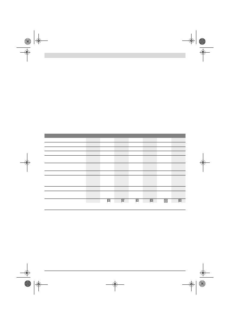
Suomi |
59
Bosch Power Tools
1 619 929 J37 | (2.2.12)
Kuvassa olevat osat
Kuvassa olevien osien numerointi viittaa grafiikkasivussa ole-
vaan sähkötyökalun kuvaan.
1
Lisäkahva (eristetty kädensija)*
2
Lisäkahvan ruuvi*
3
Värähtelytaajuuden asetuksen säätöpyörä
(GSS 230 AE/GSS 280 AE)
4
Käynnistyskytkin
5
Käynnistyskytkimen lukituspainike
6
Pölysäiliö täydellisenä (Microfilter System)*
7
Kuusiokoloavain
8
Kiristyssanka
9
Hiomalevy
10
Kiinnitin
11
Kahva (eristetty kädensija)
12
Pölysäiliön pidike*
13
Muoviliuku
14
Poistoilma-adapteri
15
Pölysäiliön lukkovipu*
16
Suodatin (Microfilter System)*
17
Imuadapteri*
18
Imuletku*
19
Hiomapaperi*
20
Rei’itin*
21
Hiomalevyn ruuvit
22
Ohut hiomalevy, pidennetty*
23
Hiomapaperi, pidennetty*
24
Pidennetyn hiomalevyn ruuvit*
25
Hiomapaperi, kolmionmuotoinen*
26
Kolmionmuotoinen hiomalevy, pidennetty*
*Kuvassa tai selostuksessa esiintyvä lisätarvike ei kuulu vakiotoi-
mitukseen. Löydät täydellisen tarvikeluettelon tarvikeohjelmas-
tamme.
Tekniset tiedot
Melu-/tärinätiedot
Melun mittausarvot on määritetty EN 60745 mukaan.
Sähkötyökalun tyypillinen A-painotettu äänenpainetaso on
76 dB(A). Epävarmuus K=3 dB.
Melutaso saattaa työn aikana ylittää 80 dB(A).
Käytä kuulonsuojaimia!
Värähtelyn yhteisarvot a
h
(kolmen suunnan vektorisumma) ja
epävarmuus K mitattuna EN 60745 mukaan:
a
h
=4,5 m/s
2
, K=1,5 m/s
2
.
Näissä ohjeissa mainittu värähtelytaso on mitattu EN 60745
standardoidun mittausmenetelmän mukaisesti ja sitä voidaan
käyttää sähkötyökalujen vertailussa. Se soveltuu myös väräh-
telyrasituksen väliaikaiseen arviointiin.
Ilmoitettu värähtelytaso vastaa sähkötyökalun pääasiallisia
käyttötapoja. Jos sähkötyökalua kuitenkin käytetään muissa
töissä, poikkeavilla vaihtotyökaluilla tai riittämättömästi huol-
lettuna, saattaa värähtelytaso poiketa. Tämä saattaa kasvat-
taa koko työaikajakson värähtelyrasitusta huomattavasti.
Värähtelyrasituksen tarkkaa arviointia varten määrätyn työ-
aikajakson aikana tulisi ottaa huomioon myös se aika, jolloin
laite on sammutettuna tai käy, mutta sitä ei tosiasiassa käyte-
tä. Tämä voi selvästi pienentää koko työaikajakson värähtely-
rasitusta.
Määrittele lisävarotoimenpiteet käyttäjän suojaksi värähtelyn
vaikutukselta, kuten esimerkiksi: Sähkötyökalujen ja vaihto-
työkalujen huolto, käsien pitäminen lämpiminä, työnkulun or-
ganisointi.
Tasohiomakone
GSS ...
230 A
230 AE
230 AE
280 A
280 AE
280 AE
Tuotenumero
0 601 ...
292 0..
292 7..
292 6..
293 0..
293 7..
293 6..
Pölysäiliö kuuluu toimitukseen
–
–
z
–
–
z
Värähtelytaajuuden asetus
–
z
z
–
z
z
Ottoteho
W
300
300
300
330
330
330
Tyhjäkäyntikierrosluku
min
-1
11000
5500
– 11000
5500
– 11000
11000
5500
– 11000
5500
– 11000
Tyhjäkäyntivärähtelytaajuus
min
-1
22000
11000
– 22000
11000
– 22000
22000
11000
– 22000
11000
– 22000
Värähtelyympyränhalkaisija
mm
2,4
2,4
2,4
2,4
2,4
2,4
Hiomapaperin mitat
— Tarrakiinnitys
— Pantakiinnitys
mm
mm
93 x 185
93 x 230
93 x 185
93 x 230
93 x 185
93 x 230
115 x 230
115 x 280
115 x 230
115 x 280
115 x 230
115 x 280
Hiomalevyn mitat
mm
92 x 182
92 x 182
92 x 182 114 x 226 114 x 226 114 x 226
Paino vastaa EPTA-Procedure
01/2003
kg
2,3
2,3
2,3
2,6
2,6
2,6
Suojausluokka
/
II
/
II
/
II
/
II
/
II
/
II
Tiedot koskevat 230 V nimellisjännitettä [U]. Poikkeavilla jännitteillä ja maakohtaisissa malleissa nämä tiedot voivat vaihdella.
Ota huomioon sähkötyökalusi mallikilvessä oleva tuotenumero. Yksittäisten koneiden kauppanimitys saattaa vaihdella.
OBJ_BUCH-426-005.book Page 59 Thursday, February 2, 2012 10:06 AM
60
| Suomi
1 619 929 J37 | (2.2.12)
Bosch Power Tools
Standardinmukaisuusvakuutus
Vakuutamme yksin vastaavamme siitä, että kohdassa ”Tekni-
set tiedot” selostettu tuote vastaa seuraavia standardeja tai
standardoituja asiakirjoja: EN 60745 direktiivien
2011/65/EU, 2004/108/EY, 2006/42/EY määräysten mu-
kaan.
Tekninen tiedosto (2006/42/EY):
Robert Bosch GmbH, PT/ETM9,
D-70745 Leinfelden-Echterdingen
Robert Bosch GmbH, Power Tools Division
D-70745 Leinfelden-Echterdingen
12.01.2012
Asennus
f
Irrota pistotulppa pistorasiasta ennen kaikkia sähkö-
työkaluun kohdistuvia töitä.
Pölyn ja lastun poistoimu
f
Materiaalien, kuten lyijypitoisen pinnoitteen, muutamien
puulaatujen, kivennäisten ja metallin pölyt voivat olla ter-
veydelle vaarallisia. Pölyn kosketus tai hengitys saattaa ai-
heuttaa käyttäjälle tai lähellä oleville henkilöille allergisia
reaktioita ja/tai hengitystiesairauksia.
Määrättyjä pölyjä, kuten tammen- tai pyökinpölyä pidetään
karsinogeenisina, eritoten yhdessä puukäsittelyssä käy-
tettyjen lisäaineiden kanssa (kromaatti, puunsuoja-aine).
Asbestipitoisia aineita saavat käsitellä vain ammattilaiset.
– Käytä materiaalille soveltuvaa pölynimua, jos se on
mahdollista.
– Huolehdi työkohteen hyvästä tuuletuksesta.
– Suosittelemme käyttämään suodatusluokan P2 hengi-
tyssuojanaamaria.
Ota huomioon maassasi voimassaolevat säännökset koski-
en käsiteltäviä materiaaleja.
f
Vältä pölynkertymää työpaikalla.
Pöly saattaa helposti
syttyä palamaan.
Sisäinen pölynimu pölysäiliöön (katso kuva A1 – A4)
Vedä ulos muoviliuku
13
ennen pölysäiliön
6
asennusta. Ase-
ta pölysäiliö
6
poistoilmanysään
14
lukittumiseen asti. Var-
mista, että muoviliuku
13
tarttuu pidikkeeseen
12
.
Tyhjennä pölysäiliö
6
painamalla painiketta pölysäiliön
15
kyl-
jessä (
n
). Vedä pölysäiliö irti alaspäin (
o
).
Ennen pölysäiliön
6
avaamista tulisi sinun kuvan osoittamalla
tavalla koputtaa pölysäiliö kiinteää alustaa vasten, jotta pöly
irtoaisi suodatinpanoksesta.
Tartu pölysäiliötä
6
tartuntasyvennyksestä, käännä suodatin-
panos
16
pois ylöspäin, ja tyhjennä pölysäiliö. Puhdista suo-
datinpanoksen lamellit
16
pehmeällä harjalla.
Ulkopuolinen poistoimu (katso kuva B)
Työnnä imuadapteri
17
poistoilmanysään
14
. Tarkista, että
imuadapterin lukkovipu lukkiutuu. Imuadapteriin
17
voidaan
liitää imuletku, jonka halkaisija on 19 mm.
Irrota imuadapteri
17
painamalla sen takana olevia lukkovipu-
ja yhteen ja vetämällä imuadapteri irti.
Pölynimurin tulee soveltua työstettävälle materiaalille.
Käytä erikoisimuria terveydelle erityisen vaarallisten, karsino-
geenisten tai kuivien pölyjen imurointiin.
Hiomapaperin vaihto
Poista lika ja pöly hiomalevystä
9
esim. siveltimellä ennen uu-
den hiomapaperin kiinnittämistä.
Tarkista parhaan mahdollisen pölynpoiston varmistamiseksi,
että hiomapaperin aukot ovat hiomalevyn reikien kohdalla.
Tarrakiinnitteiset hiomapaperit (katso kuva C)
Hiomalevyssä
9
on tarrakudos, jotta tarrakiinnitteiset hioma-
paperit voidaan kiinnittää nopeasti ja yksinkertaisesti.
Koputa hiomalevyn
9
tarrakudosta puhtaaksi ennen hiomapa-
perin
19
kiinnitystä mahdollisimman hyvän tartunnan mah-
dollistamiseksi.
Aseta hiomapaperi
19
hiomalevyn
9
toista laitaa pitkin ja sit-
ten hiomalevyyn painaen se tiukasti kiinni.
Poista hiomapaperi
19
tarttumalla siihen yhdestä kulmasta ja
vetämällä se irti hiomalevystä
9
.
Hipmapaperit ilman tarrakiinnitystä (katso kuva D)
Nosta kiinnityspantoja
8
vähäsen ja vapauta ne.
Työnnä hiomapaperi
19
vasteeseen asti taaemman avatun
kiinnittimen
10
alle ja kiristä hiomapaperi kiinnittämällä kiin-
nityspanta
8
.
Aseta hiomapaperi
19
tiukasti kiinni hiomalevyyn. Työnnä
hiomapaperin
19
toinen pää etummaisen kiinnittimen
10
alle
ja kiristä hiomapaperi kiinnittämällä kiinnityspanta
8
.
Reiättömiä hiomapaapereita, esim. rulla- tai metritavaraa, voi
rei’ittää pölynimua varten rei’ittimellä
20
. Paina sähkötyökalu
asennettuine hiomapapereineen rei'itintä vasten
(katso kuva E).
Irrota hiomapaperi
19
avaamalla kiinnityspannat
8
ja vetä-
mällä hiomapaperi ulos.
Hiomapaperin valinta
Riippuen hiottavasta materiaalista ja pinnan halutusta hioma-
tehosta on saatavissa erilaisia hiomapapereita:
Dr. Egbert Schneider
Senior Vice President
Engineering
Dr. Eckerhard Strötgen
Engineering Director
PT/ESI
Karkeus
40–400
Kaikkien puuaineiden
käsittelyyn
Karkeiden, höyläämättömien
palkkien ja lautojen esihiontaan
karkea 40, 60
Tasohiontaan ja pienien epätasai-
suuksien tasoitukseen
keski-
karkea
80, 100, 120
Kovan puun viimeistely- ja
hienohiontaan
hieno
180, 240,
320, 400
OBJ_BUCH-426-005.book Page 60 Thursday, February 2, 2012 10:06 AM
Suomi |
61
Bosch Power Tools
1 619 929 J37 | (2.2.12)
Hiomalevyn vaihto (katso kuva F)
Hiomalevyn
9
voi tarvittaessa vaihtaa.
Kierrä kokonaan irti 6 ruuvia
21
ja poista hiomalevy
9
. Aseta
uusi hiomalevy
9
paikoilleen ja kiristä ruuvit uudelleen.
Erikoishiomalevyt
Voit vaihtaa toimitukseen kuuluva hiomalevy
9
lisätarvikkee-
na saatavaan erikoishiomalevyyn.
Erikoishiomalevyn asennus tapahtuu kuten toimitukseen kuu-
luvan hiomalevyn.
Kaikkien hiomatarvikkeiden kiinnitys ja irrotus tehdän kuten
alkuperäisen hiomapaperin vaihto.
Pidennetty hiomalevy, nelikulmainen, ohut
(GSS 230 A/GSS 230 AE) (katso kuva G)
Nelikulmaisen, ohuen, pidennetyn hiomalevyn
22
käyttö
mahdollistaa hiomisen vaikeasti päästävissä kohteissa ja ah-
taissa väliköissä, esimerkiksi ikkuna- tai ovisäleissä, urissa tai
lämpöpattereiden tai vesiputkien takana.
Käytä toimitukseen kuuluvia ruuveja
24
pidennetyn hiomale-
vyn
22
asennuksessa.
Pidennetty hiomalevy, kolmionmuotoinen
(GSS 230 A/GSS 230 AE) (katso kuva H)
Kolmionmuotoisen pidennetyn hiomalevyn
26
käyttö mah-
dollistaa hiomisen kulmissa ja reunoissa.
Viimeistelyhiomalevy (ilman tarrakiinnitystä)
(GSS 230 AE/GSS 280 AE) (katso kuva D)
Käyttäessäsi pääasiassa vakiohiomapapereita, joissa ei ole
tarrapintaa, kannattaa käyttää viimeistelyhiomalevyä, ilman
tarrakiinnitystä. Hiomalevyn tasaisen pinnan ansiosta saavu-
tetaan etenkin viimeistelyhionnassa paras mahdollinen hion-
tatulos.
Lisäkahva
Lisäkahva
1
mahdollistaa mukavan käsittelyn ja optimaalisen
voimanjaon, etenkin suurella hiontateholla.
Kiinnitä lisäkahva
1
koteloon ruuvilla
2
.
Käyttö
Käyttöönotto
f
Ota huomioon verkkojännite! Virtalähteen jännitteen
tulee vastata laitteen tyyppikilvessä olevia tietoja.
230 V merkittyjä laitteita voidaan käyttää myös 220 V
verkoissa.
Käynnistys ja pysäytys
Paina sähkötyökalun
käynnistystä varten
käynnistyskytkin-
tä
4
ja pidä se painettuna.
Lukitse
painettu käynnistyskytkin
4
painamalla lukituspaini-
ketta
5
.
Pysäytä
sähkötyökalu päästämällä käynnistyskytkin
4
va-
paaksi tai, jos se on lukittu lukituspainikkeella
5
, paina ensin
käynnistyskytkintä
4
lyhyesti ja päästä se sitten vapaaksi.
Värähtelytaajuuden asetus (GSS 230 AE/GSS 280 AE)
Värähtelytaajuuden asetuksen säätöpyörällä
3
voit asettaa
tarvittavan värähtelytaajuuden myös käytön aikana.
Tarvittava värähtelytaajuus riippuu materiaalista ja työolo-
suhteista ja se voidaan määrittää käytännön kokein.
Työskentelyohjeita
f
Odota, kunnes sähkötyökalu on pysähtynyt, ennen
kuin asetat sen pois käsistäsi.
Poistoteho hiottaessa määräytyy pääasiassa hiomapaperin
valinnalla sekä asetetulla värähtelytaajuudella (GSS 230 AE/
GSS 280 AE).
Vain moitteettomassa kunnossa olevat hiomapaperit antavat
hyvän hiontatehon ja säästävät sähkötyökalua.
Kiinnitä huomiota tasaiseen puristuspaineeseen, hiomapape-
rin kestoiän kasvattamiseksi.
Paineen turha lisääminen ei paranna hiontatehoa, vaan johtaa
laitteen ja hiomapaperin voimakkaampaan kulumiseen.
Hiomapaperi, jolla on hiottu metallia, ei tulisi käyttää muita
materiaaleja varten.
Käytä vain alkuperäisiä Bosch-hiomatarvikkeita.
Hoito ja huolto
Huolto ja puhdistus
f
Irrota pistotulppa pistorasiasta ennen kaikkia sähkö-
työkaluun kohdistuvia töitä.
f
Pidä aina sähkötyökalua ja sähkötyökalun tuuletusauk-
koja puhtaana, jotta voit työskennellä hyvin ja turvalli-
sesti.
Jos liitäntäjohdon vaihto on välttämätön, tulee tämän suorit-
taa Bosch tai Bosch-sähkötyökalujen sopimushuolto turvalli-
suuden vaarantamisen välttämiseksi.
Jos sähkötyökalussa huolellisesta valmistuksesta ja koestus-
menettelystä huolimatta esiintyy vikaa, tulee korjaus antaa
Bosch-keskushuollon tehtäväksi.
Ilmoita kaikissa kyselyissä ja varaosatilauksissa 10-numeroi-
nen tuotenumero, joka löytyy laitteen mallikilvestä.
40–320
Maali-/lakkapintojen sekä poh-
justusten kuten fillerin ja spak-
kelin työstöön
Värin poistohiontaan
karkea 40, 60
Pohjamaalin hiontaan
keski-
karkea
80, 100, 120
Pohjustuksen lopulliseen
hiontaan ennen lakkausta
hieno
180, 240, 320
Karkeus
OBJ_BUCH-426-005.book Page 61 Thursday, February 2, 2012 10:06 AM
62
| EëëçíéêÜ
1 619 929 J37 | (2.2.12)
Bosch Power Tools
Huolto ja asiakasneuvonta
Huolto vastaa tuotteesi korjausta ja huoltoa sekä varaosia
koskeviin kysymyksiin. Räjähdyspiirustuksia ja tietoja vara-
osista löydät myös osoitteesta:
www.bosch-pt.com
Bosch-asiakasneuvonta auttaa mielellään sinua tuotteiden ja
lisätarvikkeiden ostoa, käyttöä ja säätöä koskevissa kysymyk-
sissä.
Suomi
Robert Bosch Oy
Bosch-keskushuolto
Pakkalantie 21 A
01510 Vantaa
Puh.: 0800 98044
Faksi: +358 102 961 838
www.bosch.fi
Hävitys
Sähkötyökalu, lisätarvikkeet ja pakkaukset tulee toimittaa
ympäristöystävälliseen uusiokäyttöön.
Älä heitä sähkötyökaluja talousjätteisiin!
Vain EU-maita varten:
Eurooppalaisen vanhoja sähkö- ja elektro-
niikkalaitteita koskevan direktiivin
2002/96/EY ja sen kansallisten lakien
muunnosten mukaan, tulee käyttökelvotto-
mat sähkötyökalut kerätä erikseen ja toimit-
taa ympäristöystävälliseen uusiokäyttöön.
Oikeus teknisiin muutoksiin pidätetään.
ÅëëçíéêÜ
Õðïäåßîåéò áóöáëåßáò
ÃåíéêÝò õðïäåßîåéò áóöáëåßáò ãéá çëåêôñéêÜ
åñãáëåßá
ÄéáâÜóôå üëåò ôéò õðïäåßîåéò
áóöáëåßáò êáé ôéò ïäçãßåò.
ÁìÝëåéåò êáôÜ ôçí ôÞñçóç ôùí õðïäåßîåùí áóöáëåßáò êáé ôùí
ïäçãéþí ìðïñåß íá ðñïêáëÝóïõí çëåêôñïðëçîßá, ðõñêáãéÜ
Þ/êáé óïâáñïýò ôñáõìáôéóìïýò.
ÖõëÜîôå üëåò ôéò ðñïåéäïðïéçôéêÝò õðïäåßîåéò êáé ïäçãßåò
ãéá êÜèå ìåëëïíôéêÞ ÷ñÞóç.
Ï ïñéóìüò «Çëåêôñéêü åñãáëåßï» ðïõ ÷ñçóéìïðïéåßôáé óôéò
ðñïåéäïðïéçôéêÝò õðïäåßîåéò áíáöÝñåôáé óå çëåêôñéêÜ
åñãáëåßá ðïõ ôñïöïäïôïýíôáé áðü ôï çëåêôñéêü äßêôõï (ìå
çëåêôñéêü êáëþäéï) êáèþò êáé óå çëåêôñéêÜ åñãáëåßá ðïõ
ôñïöïäïôïýíôáé áðü ìðáôáñßá (÷ùñßò çëåêôñéêü êáëþäéï).
ÁóöÜëåéá óôï ÷þñï åñãáóßáò
f
Äéáôçñåßôå ôïí ôïìÝá ðïõ åñãÜæåóèå êáèáñü êáé êáëÜ
öùôéóìÝíï.
Áôáîßá Þ óêïôåéíÝò ðåñéï÷Ýò åñãáóßáò ìðïñåß
íá ïäçãÞóïõí óå áôõ÷Þìáôá.
f
Ìçí åñãÜæåóèå ìå ôï çëåêôñéêü åñãáëåßï óå
ðåñéâÜëëïí üðïõ õðÜñ÷åé êßíäõíïò Ýêñçîçò, óôï ïðïßï
õðÜñ÷ïõí åýöëåêôá õãñÜ, áÝñéá Þ óêüíåò.
Ôá çëåêôñéêÜ
åñãáëåßá äçìéïõñãïýí óðéíèçñéóìü ï ïðïßïò ìðïñåß íá
áíáöëÝîåé ôç óêüíç Þ ôéò áíáèõìéÜóåéò.
f
¼ôáí ÷ñçóéìïðïéåßôå ôï çëåêôñéêü åñãáëåßï êñáôÜôå
ìáêñéÜ áð’ áõôü ôá ðáéäéÜ êé Üëëá ôõ÷üí
ðáñåõñéóêüìåíá Üôïìá.
Óå ðåñßðôùóç áðüóðáóçò ôçò
ðñïóï÷Þò óáò ìðïñåß íá ÷Üóåôå ôïí Ýëåã÷ï ôïõ ìç÷áíÞ-
ìáôïò.
ÇëåêôñéêÞ áóöÜëåéá
f
Ôï öéò ôïõ çëåêôñéêïý åñãáëåßïõ ðñÝðåé íá ôáéñéÜæåé
óôçí ðñßæá. Äåí åðéôñÝðåôáé ìå êáíÝíáí ôñüðï ç
ìåôáôñïðÞ ôïõ öéò. Ìç ÷ñçóéìïðïéåßôå ðñïóáñìïóôéêÜ
öéò óå óõíäõáóìü ìå ãåéùìÝíá çëåêôñéêÜ åñãáëåßá.
Áìåôáðïßçôá öéò êáé êáôÜëëçëåò ðñßæåò ìåéþíïõí ôïí
êßíäõíï çëåêôñïðëçîßáò.
f
Áðïöåýãåôå ôçí åðáöÞ ôïõ óþìáôüò óáò ìå ãåéùìÝíåò
åðéöÜíåéåò üðùò óùëÞíåò, èåñìáíôéêÜ óþìáôá
(êáëïñéöÝñ), êïõæßíåò Þ øõãåßá.
¼ôáí ôï óþìá óáò åßíáé
ãåéùìÝíï áõîÜíåôáé ï êßíäõíïò çëåêôñïðëçîßáò.
f
Ìçí åêèÝôåôå ôá ìç÷áíÞìáôá óôç âñï÷Þ Þ ôçí õãñáóßá.
Ç äéåßóäõóç íåñïý ó’ Ýíá çëåêôñéêü åñãáëåßï áõîÜíåé ôïí
êßíäõíï çëåêôñïðëçîßáò.
f
Ìç ÷ñçóéìïðïéåßôå ôï çëåêôñéêü êáëþäéï ãéá íá
ìåôáöÝñåôå Þ íá áíáñôÞóåôå ôï çëåêôñéêü åñãáëåßï, Þ
ãéá íá âãÜëåôå ôï öéò áðü ôçí ðñßæá. ÊñáôÜôå ôï çëåê-
ôñéêü êáëþäéï ìáêñéÜ áðü õðåñâïëéêÝò èåñìïêñáóßåò,
êïöôåñÝò áêìÝò êáé/Þ áðü êéíçôÜ åîáñôÞìáôá.
Ôõ÷üí
÷áëáóìÝíá Þ ðåñéðëåãìÝíá çëåêôñéêÜ êáëþäéá áõîÜíïõí
ôïí êßíäõíï çëåêôñïðëçîßáò.
f
¼ôáí åñãÜæåóèå ì’ Ýíá çëåêôñéêü åñãáëåßï óôï ýðáéèñï
íá ÷ñçóéìïðïéåßôå êáëþäéá åðéìÞêõíóçò (ìðáëáíôÝæåò)
ðïõ åßíáé êáôÜëëçëá êáé ãéá ÷ñÞóç óôï ýðáéèñï.
Ç ÷ñÞóç
êáëùäßùí åðéìÞêõíóçò êáôÜëëçëùí ãéá õðáßèñéïõò ÷þñïõò
åëáôôþíåé ôïí êßíäõíï çëåêôñïðëçîßáò.
f
¼ôáí ç ÷ñÞóç ôïõ çëåêôñéêïý åñãáëåßïõ óå õãñü
ðåñéâÜëëïí åßíáé áíáðüöåõêôç, ôüôå ÷ñçóéìïðïéÞóôå
Ýíáí ðñïóôáôåõôéêü äéáêüðôç äéáññïÞò (äéáêüðôç
FI/RCD).
Ç ÷ñÞóç åíüò ðñïóôáôåõôéêïý äéáêüðôç äéáññïÞò
åëáôôþíåé ôïí êßíäõíï çëåêôñïðëçîßáò.
ÁóöÜëåéá ðñïóþðùí
f
Íá åßóôå ðÜíôïôå ðñïóåêôéêüò/ðñïóåêôéêÞ, íá äßíåôå
ðñïóï÷Þ óôçí åñãáóßá ðïõ êÜíåôå êáé íá ÷åéñßæåóôå ôï
ìç÷Üíçìá ìå ðåñßóêåøç. Ìç ÷ñçóéìïðïéÞóåôå Ýíá
çëåêôñéêü åñãáëåßï üôáí åßóôå êïõñáóìÝíïò/
êïõñáóìÝíç Þ üôáí âñßóêåóôå õðü ôçí åðÞñåéá
íáñêùôéêþí, ïéíïðíåýìáôïò Þ öáñìÜêùí.
Ìéá óôéãìéáßá
áðñïóåîßá êáôÜ ôï ÷åéñéóìü ôïõ çëåêôñéêïý åñãáëåßïõ
ìðïñåß íá ïäçãÞóåé óå óïâáñïýò ôñáõìáôéóìïýò.
f
ÖïñÜôå Ýíáí êáôÜëëçëï ãéá óáò ðñïóôáôåõôéêü
åîïðëéóìü êáé ðÜíôïôå ðñïóôáôåõôéêÜ ãõáëéÜ.
¼ôáí
öïñÜôå Ýíáí êáôÜëëçëï ðñïóôáôåõôéêü åîïðëéóìü üðùò
ìÜóêá ðñïóôáóßáò áðü óêüíç, áíôéïëéóèçôéêÜ õðïäÞìáôá
áóöáëåßáò, ðñïóôáôåõôéêü êñÜíïò Þ ùôáóðßäåò, áíÜëïãá ìå
ôï åêÜóôïôå åñãáëåßï êáé ôç ÷ñÞóç ôïõ, åëáôôþíåôáé ï
êßíäõíïò ôñáõìáôéóìþí.
OBJ_BUCH-426-005.book Page 62 Thursday, February 2, 2012 10:06 AM
EëëçíéêÜ |
63
Bosch Power Tools
1 619 929 J37 | (2.2.12)
f
Áðïöåýãåôå ôçí áèÝëçôç åêêßíçóç. Âåâáéùèåßôå üôé ôï
çëåêôñéêü åñãáëåßï Ý÷åé áðïæåõ÷ôåß ðñéí ôï óõíäÝóåôå
ìå ôï çëåêôñéêü äßêôõï Þ ìå ôçí ìðáôáñßá êáèþò êáé ðñéí
ôï ðáñáëÜâåôå Þ ôï ìåôáöÝñåôå.
¼ôáí ìåôáöÝñåôå ôï
çëåêôñéêü åñãáëåßï Ý÷ïíôáò ôï äÜ÷ôõëü óáò óôï äéáêüðôç Þ
üôáí óõíäÝóåôå ôï ìç÷Üíçìá ìå ôçí ðçãÞ ñåýìáôïò üôáí
áõôü åßíáé áêüìç óôç èÝóç ÏÍ, ôüôå äçìéïõñãåßôáé êßíäõíïò
ôñáõìáôéóìþí.
f
Áöáéñåßôå áðü ôá çëåêôñéêÜ åñãáëåßá ôõ÷üí
óõíáñìïëïãçìÝíá åñãáëåßá ñýèìéóçò Þ êëåéäéÜ ðñéí
èÝóåôå ôï çëåêôñéêü åñãáëåßï óå ëåéôïõñãßá.
¸íá åñãá-
ëåßï Þ êëåéäß óõíáñìïëïãçìÝíï ó’ Ýíá ðåñéóôñåöüìåíï
ôìÞìá åíüò ìç÷áíÞìáôïò ìðïñåß íá ïäçãÞóåé óå ôñáõìáôéó-
ìïýò.
f
Ìçí õðåñåêôéìÜôå ôïí åáõôü óáò. Öñïíôßæåôå ãéá ôçí
áóöáëÞ óôÜóç ôïõ óþìáôüò óáò êáé äéáôçñåßôå ðÜíôïôå
ôçí éóïññïðßá óáò.
¸ôóé ìðïñåßôå íá åëÝãîåôå êáëýôåñá ôï
ìç÷Üíçìá óå ðåñéðôþóåéò áðñïóäüêçôùí ðåñéóôÜóåùí.
f
ÖïñÜôå êáôÜëëçëá åíäýìáôá. Ìç öïñÜôå öáñäéÜ
ñïý÷á Þ êïóìÞìáôá. ÊñáôÜôå ôá ìáëëéÜ óáò, ôá ñïý÷á
óáò êáé ôá ãÜíôéá óáò ìáêñéÜ áðü êéíïýìåíá
åîáñôÞìáôá.
×áëáñÞ åíäõìáóßá, êïóìÞìáôá Þ ìáêñéÜ
ìáëëéÜ ìðïñåß íá åìðëáêïýí óôá êéíïýìåíá åîáñôÞìáôá.
f
¼ôáí õðÜñ÷åé ç äõíáôüôçôá óõíáñìïëüãçóçò
äéáôÜîåùí áíáññüöçóçò Þ óõëëïãÞò óêüíçò,
âåâáéùèåßôå üôé áõôÝò åßíáé óõíäåìÝíåò ìå ôï ìç÷Üíçìá
êáèþò êáé üôé ÷ñçóéìïðïéïýíôáé óùóôÜ.
Ç ÷ñÞóç ìéáò
áíáññüöçóçò óêüíçò ìðïñåß íá åëáôôþóåé ôïí êßíäõíï ðïõ
ðñïêáëåßôáé áðü ôç óêüíç.
ÅðéìåëÞò ÷åéñéóìüò êáé ÷ñÞóç çëåêôñéêþí åñãáëåßùí
f
Ìçí õðåñöïñôþíåôå ôï ìç÷Üíçìá. ×ñçóéìïðïéåßôå ãéá
ôçí åêÜóôïôå åñãáóßá ôï çëåêôñéêü åñãáëåßï ðïõ
ðñïïñßæåôáé ãé’ áõôÞí.
Ìå ôï êáôÜëëçëï çëåêôñéêü åñãá-
ëåßï åñãÜæåóôå êáëýôåñá êáé áóöáëÝóôåñá óôçí
áíáöåñüìåíç ðåñéï÷Þ éó÷ýïò.
f
Ìç ÷ñçóéìïðïéÞóåôå ðïôÝ Ýíá ìç÷Üíçìá ðïõ Ý÷åé
÷áëáóìÝíï äéáêüðôç.
¸íá çëåêôñéêü åñãáëåßï ðïõ äåí
ìðïñåßôå ðëÝïí íá ôï èÝóåôå óå ëåéôïõñãßá êáé/Þ åêôüò ëåé-
ôïõñãßáò åßíáé åðéêßíäõíï êáé ðñÝðåé íá åðéóêåõáóôåß.
f
ÂãÜëôå ôï öéò áðü ôçí ðñßæá êáé/Þ áöáéñÝóôå ôçí
ìðáôáñßá ðñéí äéåîÜãåôå óôï ìç÷Üíçìá ìéá ïðïéáäÞðïôå
åñãáóßá ñýèìéóçò, ðñéí áëëÜîåôå Ýíá åîÜñôçìá Þ üôáí
ðñüêåéôáé íá äéáöõëÜîåôå/íá áðïèçêåýóåôå ôï
ìç÷Üíçìá.
ÁõôÜ ôá ðñïëçðôéêÜ ìÝôñá áóöáëåßáò ìåéþíïõí
ôïí êßíäõíï áðü ôõ÷üí áèÝëçôç åêêßíçóç ôïõ çëåêôñéêïý
åñãáëåßïõ.
f
ÄéáöõëÜãåôå ôá çëåêôñéêÜ åñãáëåßá ðïõ äå
÷ñçóéìïðïéåßôå ìáêñéÜ áðü ðáéäéÜ. Ìçí åðéôñÝøåôå ôç
÷ñÞóç ôïõ ìç÷áíÞìáôïò óå Üôïìá ðïõ äåí åßíáé
åîïéêåéùìÝíá ì’ áõôü Þ äåí Ý÷ïõí äéáâÜóåé ôéò ðáñïýóåò
ïäçãßåò.
Ôá çëåêôñéêÜ åñãáëåßá åßíáé åðéêßíäõíá üôáí
÷ñçóéìïðïéïýíôáé áðü Üðåéñá ðñüóùðá.
f
Íá ðåñéðïéåßóôå ðñïóåêôéêÜ ôï çëåêôñéêü åñãáëåßï.
ÅëÝã÷åôå, áí ôá êéíïýìåíá åîáñôÞìáôá ëåéôïõñãïýí
Üøïãá, ÷ùñßò íá ìðëïêÜñïõí, Þ ìÞðùò Ý÷ïõí óðÜóåé Þ
öèáñåß ôõ÷üí åîáñôÞìáôá ôá ïðïßá åðçñåÜæïõí ôïí
ôñüðï ëåéôïõñãßáò ôïõ çëåêôñéêïý åñãáëåßïõ. Äþóôå
áõôÜ ôá ÷áëáóìÝíá åîáñôÞìáôá ãéá åðéóêåõÞ ðñéí ôá
îáíá÷ñçóéìïðïéÞóåôå.
Ç êáêÞ óõíôÞñçóç ôùí çëåêôñéêþí
åñãáëåßùí áðïôåëåß áéôßá ðïëëþí áôõ÷çìÜôùí.
f
Äéáôçñåßôå ôá åñãáëåßá êïðÞò êïöôåñÜ êáé êáèáñÜ.
ÐñïóåêôéêÜ óõíôçñçìÝíá êïðôéêÜ åñãáëåßá óöçíþíïõí
äõóêïëüôåñá êáé ïäçãïýíôáé åõêïëüôåñá.
f
×ñçóéìïðïéåßôå ôá çëåêôñéêÜ åñãáëåßá, åîáñôÞìáôá,
ðáñåëêüìåíá åñãáëåßá êôë. óýìöùíá ìå ôéò ðáñïýóåò
ïäçãßåò. ËáìâÜíåôå åðßóçò õðüøç óáò ôéò åêÜóôïôå
óõíèÞêåò êáé ôçí õðü åêôÝëåóç åñãáóßá.
Ç
÷ñçóéìïðïßçóç ôùí çëåêôñéêþí åñãáëåßùí ãéá åñãáóßåò ðïõ
äåí ðñïâëÝðïíôáé ãé’ áõôÜ ìðïñåß íá äçìéïõñãÞóåé åðéêßíäõ-
íåò êáôáóôÜóåéò.
Service
f
Äþóôå ôï çëåêôñéêü åñãáëåßï óáò ãéá åðéóêåõÞ áðü
Üñéóôá åêðáéäåõìÝíï ðñïóùðéêü êáé ìå ãíÞóéá
áíôáëëáêôéêÜ.
¸ôóé åîáóöáëßæåôå ôç äéáôÞñçóç ôçò áóöÜ-
ëåéáò ôïõ ìç÷áíÞìáôïò.
Õðïäåßîåéò áóöáëåßáò ãéá ëåéáíôÞñåò
f
×ñçóéìïðïéåßôå ôï çëåêôñéêü åñãáëåßï ìüíï ãéá îçñÞ
ëåßáíóç.
Ç äéåßóäõóç íåñïý óå ìéá çëåêôñéêÞ óõóêåõÞ
áõîÜíåé ôïí êßíäõíï çëåêôñïðëçîßáò.
f
Ðñïóï÷Þ, êßíäõíïò ðõñêáãéÜò! Íá áðïöåýãåôå ôçí
õðåñâïëéêÞ èÝñìáíóç ôïõ õðü ëåßáíóç õëéêïý êáé ôïõ
ëåéáíôÞñá. Íá áäåéÜæåôå ðÜíôïôå ôï äï÷åßï óêüíçò üôáí
êÜíåôå äéÜëåéììá áðü ôçí åñãáóßá óáò.
Óêüíç ëåßáíóçò
óôï óÜêï óêüíçò, óôï Microfilter, Þ óôï ÷Üñôéíï óÜêï óêüíçò
(Þ óôï óÜêï ößëôñïõ Þ óôï ößëôñï ôïõ áðïññïöçôÞñá
óêüíçò) ìðïñåß, õðü äõóìåíåßò óõíèÞêåò, ð.÷. åîáéôßáò ôïõ
óðéíèçñéóìïý êáôÜ ôç ëåßáíóç ìåôÜëëùí, íá
áõôáíáöëå÷èåß. Áõôüò ï êßíäõíïò áõîÜíåôáé éäéáéôÝñùò üôáí
ç óêüíç ëåßáíóçò áíáìåéãíýåôáé ìå êáôÜëïéðá âåñíéêéþí
Þ/êáé ðïëõïõñåèÜíçò, Þ ìå Üëëá ÷çìéêÜ õëéêÜ, êáé
ôáõôü÷ñïíá, ìåôÜ áðü óõíå÷Þ åñãáóßá, ôï õðü ëåßáíóç õëéêü
Ý÷åé èåñìáíèåß õðåñâïëéêÜ.
f
¼ôáí åñãÜæåóèå íá êñáôÜôå ôï çëåêôñéêü åñãáëåßï
êáëÜ êáé ìå ôá äõï óáò ÷Ýñéá êáé íá öñïíôßæåôå ãéá ôçí
áóöáëÞ èÝóç ôïõ óþìáôüò óáò.
Ôï çëåêôñéêü åñãáëåßï
ïäçãåßôáé áóöáëÝóôåñá üôáí ôï êñáôÜôå êáé ìå ôá äõï óáò
÷Ýñéá.
f
Áóöáëßæåôå ôï õðü êáôåñãáóßá ôåìÜ÷éï.
¸íá õðü
êáôåñãáóßá ôåìÜ÷éï óõãêñáôéÝôáé áóöáëÝóôåñá ìå ìéá
äéÜôáîç óýóöéãîçò Þ ìå ìéá ìÝããåíç ðáñÜ ìå ôï ÷Ýñé óáò.
ÐåñéãñáöÞ ôïõ ðñïúüíôïò êáé ôçò
éó÷ýïò ôïõ
ÄéáâÜóôå üëåò ôéò õðïäåßîåéò áóöáëåßáò êáé
ôéò ïäçãßåò.
ÁìÝëåéåò êáôÜ ôçí ôÞñçóç ôùí
õðïäåßîåùí áóöáëåßáò êáé ôùí ïäçãéþí ìðïñåß
íá ðñïêáëÝóïõí çëåêôñïðëçîßá, ðõñêáãéÜ
Þ/êáé óïâáñïýò ôñáõìáôéóìïýò.
Ðáñáêáëïýìå áíïßîôå ôç äéðëùìÝíç óåëßäá ìå ôçí áðåéêüíéóç
ôçò óõóêåõÞò êé áöÞóôå ôçí áíïé÷ôÞ üóï èá äéáâÜæåôå ôéò
ïäçãßåò ÷åéñéóìïý.
OBJ_BUCH-426-005.book Page 63 Thursday, February 2, 2012 10:06 AM
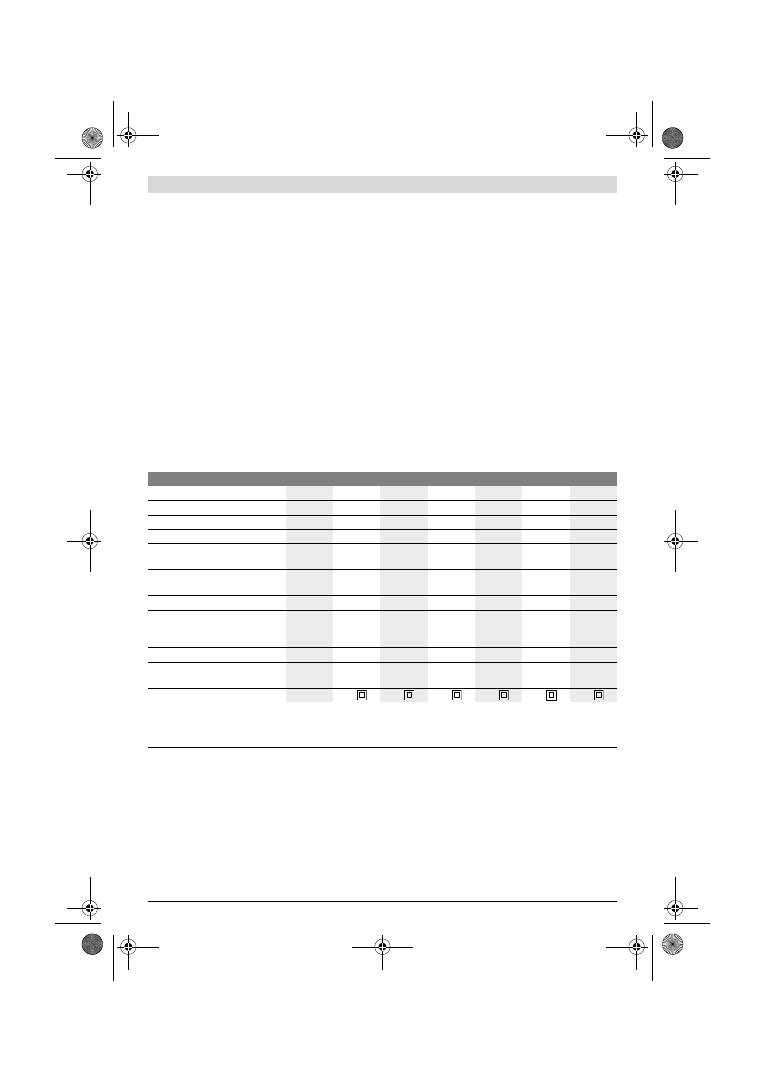
64
| EëëçíéêÜ
1 619 929 J37 | (2.2.12)
Bosch Power Tools
×ñÞóç óýìöùíá ìå ôïí ðñïïñéóìü
Ç óõóêåõÞ ðñïïñßæåôáé ãéá ôçí îçñÞ ëåßáíóç îýëïõ, ðëáóôéêþí,
õëéêþí óôïêáñßóìáôïò êáèþò êáé âåñíéêùìÝíùí åðéöáíåéþí.
Áðåéêïíéæüìåíá óôïé÷åßá
Ç áðáñßèìçóç ôùí áðåéêïíéæüìåíùí óôïé÷åßùí áíáöÝñåôáé
óôçí áðåéêüíéóç ôïõ çëåêôñéêïý åñãáëåßïõ óôç óåëßäá
ãñáöéêþí.
1
Ðñüóèåôç ëáâÞ (ìïíùìÝíç åðéöÜíåéá ðéáóßìáôïò)*
2
Âßäá ãéá ðñüóèåôç ëáâÞ*
3
Ôñï÷ßóêïò ñýèìéóçò ðñïåðéëïãÞò áñéèìïý ôáëáíôþóåùí
(GSS 230 AE/GSS 280 AE)
4
Äéáêüðôçò ON/OFF
5
ÐëÞêôñï áêéíçôïðïßçóçò äéáêüðôç ON/OFF
6
Êïõôß óêüíçò êïìðëÝ (Microfilter System)*
7
Êëåéäß ôýðïõ ¢ëåí
8
¸ëáóìá óýóöéîçò
9
ÐëÜêá ëåßáíóçò
10
¸ëáóìá óýóöéîçò
11
ËáâÞ (ìïíùìÝíç åðéöÜíåéá ðéáóßìáôïò)
12
ÓõãêñáôÞñáò ãéá êïõôß óêüíçò*
13
Ðëáóôéêüò óýñôçò
14
ÓôÞñéãìá åîüäïõ áÝñá
15
Ìï÷ëüò ìáíäÜëùóçò ãéá êïõôß óêüíçò*
16
Óôïé÷åßï ößëôñïõ (Microfilter System)*
17
ÐñïóÜñôçìá áíáññüöçóçò*
18
ÓùëÞíáò áíáññüöçóçò*
19
Öýëëï ëåßáíóçò*
20
Äéáôñçôéêü åñãáëåßï*
21
Âßäåò ãéá ðëÜêá ëåßáíóçò
22
ÐëÜêá ëåßáíóçò, ëåðôÞ, åðéìçêõìÝíç*
23
Öýëëï ëåßáíóçò, åðéìçêõìÝíï*
24
Âßäåò ãéá åðéìçêõìÝíç ðëÜêá ëåßáíóçò*
25
Öýëëï ëåßáíóçò, ôñéãùíéêü*
26
ÐëÜêá ëåßáíóçò, ôñéãùíéêÞ, åðéìçêõìÝíç,*
*ÅîáñôÞìáôá ðïõ áðåéêïíßæïíôáé Þ ðåñéãñÜöïíôáé äåí ðåñéÝ÷ïíôáé
óôç óôÜíôáñ óõóêåõáóßá. Ãéá ôïí ðëÞñç êáôÜëïãï åîáñôçìÜôùí
êïßôá ôï ðñüãñáììá åîáñôçìÜôùí.
Ôå÷íéêÜ ÷áñáêôçñéóôéêÜ
Ðëçñïöïñßåò ãéá èüñõâï êáé äïíÞóåéò
Ïé ôéìÝò ìÝôñçóçò ôïõ èïñýâïõ åîáêñéâþèçêáí êáôÜ
EN 60745.
Ç ÷áñáêôçñéóôéêÞ óôÜèìç áêïõóôéêÞò ðßåóçò ôïõ ìç÷áíÞìáôïò
åîáêñéâþèçêå óýìöùíá ìå ôçí êáìðýëç Á êáé áíÝñ÷åôáé óå
76 dB(A). ÁíáóöÜëåéá K=3 dB.
¼ôáí åñãÜæåóèå ç óôÜèìç èïñýâïõ ìðïñåß íá îåðåñÜóåé ôá
80 dB(A).
ÖïñÜôå ùôáóðßäåò!
Ïé óõíïëéêÝò ôéìÝò êñáäáóìþí a
h
(Üèñïéóìá áíõóìÜôùí ôñéþí
êáôåõèýíóåùí) êáé áíáóöÜëåéá Ê åîáêñéâùèÞêáí óýìöùíá ìå
ôï ðñüôõðï EN 60745:
a
h
=4,5 m/s
2
, K=1,5 m/s
2
.
Ç óôÜèìç êñáäáóìþí ðïõ áíáöÝñåôáé ó’ áõôÝò ôéò ïäçãßåò Ý÷åé
ìåôñçèåß óýìöùíá ìå ìéá äéáäéêáóßá ìÝôñçóçò ôõðïðïéçìÝíç
óôï ðëáßóéï ôïõ ðñïôýðïõ EN 60745 êáé ìðïñåß íá
÷ñçóéìïðïéçèåß óôç óýãêñéóç ôùí äéÜöïñùí çëåêôñéêþí
åñãáëåßùí. Åßíáé åðßóçò êáôÜëëçëç ãéá Ýíáí ðñïóùñéíü õðï-
ëïãéóìü ôçò åðéâÜñõíóçò áðü ôïõò êñáäáóìïýò.
Ðáëìéêü ôñéâåßï
GSS ...
230 A
230 AE
230 AE
280 A
280 AE
280 AE
Áñéèìüò åõñåôçñßïõ
0 601 ...
292 0..
292 7..
292 6..
293 0..
293 7..
293 6..
Êïõôß óêüíçò óôç óõóêåõáóßá
–
–
z
–
–
z
ÐñïåðéëïãÞ áñéèìïý ôáëáíôþóåùí
–
z
z
–
z
z
ÏíïìáóôéêÞ éó÷ýò
W
300
300
300
330
330
330
Áñéèìüò óôñïöþí ÷ùñßò öïñôßï
min
-1
11000
5500
–
11000
5500
–
11000
11000
5500
–
11000
5500
–
11000
Áñéèìüò ôáëáíôþóåùí ÷ùñßò öïñôßï
min
-1
22000
11000
–
22000
11000
–
22000
22000
11000
–
22000
11000
–
22000
ÄéÜìåôñïò êýêëïõ ôáëÜíôùóçò
mm
2,4
2,4
2,4
2,4
2,4
2,4
ÄéáóôÜóåéò öýëëïõ ëåßáíóçò
—
Áõôïðñüóöõóç
—
ÔÜóç óýóöéîçò
mm
mm
93 x 185
93 x 230
93 x 185
93 x 230
93 x 185
93 x 230
115 x 230
115 x 280
115 x 230
115 x 280
115 x 230
115 x 280
ÄéáóôÜóåéò ðëÜêáò ëåßáíóçò
mm
92 x 182
92 x 182
92 x 182 114 x 226 114 x 226 114 x 226
ÂÜñïò óýìöùíá ìå EPTA-Procedure
01/2003
kg
2,3
2,3
2,3
2,6
2,6
2,6
Êáôçãïñßá ìüíùóçò
/
II
/
II
/
II
/
II
/
II
/
II
Ôá óôïé÷åßá éó÷ýïõí ãéá ïíïìáóôéêÝò ôÜóåéò [U] 230 V. Õðü äéáöïñåôéêÝò ôÜóåéò êáé óå åêäüóåéò åéäéêÝò ãéá ôéò äéÜöïñåò ÷þñåò ôá óôïé÷åßá áõôÜ ìðïñåß íá
äéáöÝñïõí.
Ðáñáêáëïýìå íá ðñïóÝîåôå ôïí áñéèìü åõñåôçñßïõ óôçí ðéíáêßäá êáôáóêåõáóôÞ ôïõ çëåêôñéêïý åñãáëåßïõ óáò. Ïé åìðïñéêïß ÷áñáêôçñéóìïß ïñéóìÝíùí
çëåêôñéêþí åñãáëåßùí ìðïñåß íá äéáöÝñïõí.
OBJ_BUCH-426-005.book Page 64 Thursday, February 2, 2012 10:06 AM
EëëçíéêÜ |
65
Bosch Power Tools
1 619 929 J37 | (2.2.12)
Ç óôÜèìç êñáäáóìþí ðïõ áíáöÝñåôáé áíôéðñïóùðåýåé ôéò
âáóéêÝò ÷ñÞóåéò ôïõ çëåêôñéêïý åñãáëåßïõ. Óå ðåñßðôùóç,
üìùò, ðïõ ôï çëåêôñéêü åñãáëåßï èá ÷ñçóéìïðïéçèåß
äéáöïñåôéêÜ, ìå ìç ðñïôåéíüìåíá åñãáëåßá Þ ÷ùñßò åðáñêÞ
óõíôÞñçóç, ôüôå ç óôÜèìç êñáäáóìþí ìðïñåß íá åßíáé êé áõôÞ
äéáöïñåôéêÞ. Áõôü ìðïñåß íá áõîÞóåé óçìáíôéêÜ ôçí
åðéâÜñõíóç áðü ôïõò êñáäáóìïýò êáôÜ ôç óõíïëéêÞ äéÜñêåéá
ïëüêëçñïõ ôïõ ÷ñïíéêïý äéáóôÞìáôïò ðïõ åñãÜæåóèå.
Ãéá ôçí áêñéâÞ åêôßìçóç ôçò åðéâÜñõíóçò áðü ôïõò êñáäáóìïýò
èá ðñÝðåé íá ëáìâÜíïíôáé åðßóçò õðüøç êáé ïé ÷ñüíïé êáôÜ ôç
äéÜñêåéá ôùí ïðïßùí ôï ìç÷Üíçìá âñßóêåôáé åêôüò ëåéôïõñãßáò
Þ ëåéôïõñãåß, ÷ùñßò üìùò óôçí ðñáãìáôéêüôçôá íá
÷ñçóéìïðïéåßôáé. Áõôü ìðïñåß íá ìåéþóåé óçìáíôéêÜ ôçí
åðéâÜñõíóç áðü ôïõò êñáäáóìïýò êáôÜ ôç äéÜñêåéá ïëüêëçñïõ
ôïõ ÷ñïíéêïý äéáóôÞìáôïò ðïõ åñãÜæåóèå.
Ãé’ áõôü, ðñéí áñ÷ßóåé ç äñÜóç ôùí êñáäáóìþí, íá êáèïñßæåôå
óõìðëçñùìáôéêÜ ìÝôñá áóöáëåßáò ãéá ôçí ðñïóôáóßá ôïõ
÷åéñéóôÞ üðùò: óõíôÞñçóç ôïõ çëåêôñéêïý åñãáëåßïõ êáé ôùí
åñãáëåßùí ðïõ ÷ñçóéìïðïéåßôå, æÝóôáìá ôùí ÷åñéþí, ïñãÜíùóç
ôçò åêôÝëåóçò ôùí äéÜöïñùí åñãáóéþí.
ÄÞëùóç óõìâáôüôçôáò
Äçëþíïõìå õðåõèýíùò üôé ôï ðñïúüí ðïõ ðåñéãñÜöåôáé óôá
«Ôå÷íéêÜ ÷áñáêôçñéóôéêÜ» åêðëçñþíåé ôïõò åîÞò êáíïíéóìïýò Þ
êáôáóêåõáóôéêÝò óõóôÜóåéò: EN 60745 óýìöùíá ìå ôéò
äéáôÜîåéò ôùí ïäçãéþí 2011/65/EE, 2004/108/ÅÊ,
2006/42/EÊ.
Ôå÷íéêüò öÜêåëïò (2006/42/EÊ) áðü:
Robert Bosch GmbH, PT/ETM9,
D-70745 Leinfelden-Echterdingen
Robert Bosch GmbH, Power Tools Division
D-70745 Leinfelden-Echterdingen
12.01.2012
Óõíáñìïëüãçóç
f
ÂãÜæåôå ôï öéò áðü ôçí ðñßæá ðñéí áðü ïðïéáäÞðïôå
åñãáóßá óôï çëåêôñéêü åñãáëåßï.
Áíáññüöçóç óêüíçò/ñïêáíéäéþí
f
Ç óêüíç áðü ïñéóìÝíá õëéêÜ. ð.÷. áðü ìïëõâäïý÷åò
ìðïãéÝò, áðü ìåñéêÜ åßäç îýëïõ, áðü ïñõêôÜ õëéêÜ êáé áðü
ìÝôáëëá ìðïñåß íá åßíáé áíèõãéåéíÞ. Ç åðáöÞ ìå ôç óêüíç
Þ/êáé ç åéóðíïÞ ôçò ìðïñåß íá ðñïêáëÝóåé áëëåñãéêÝò
áíôéäñÜóåéò Þ/êáé áóèÝíåéåò ôùí áíáðíåõóôéêþí ïäþí ôïõ
÷ñÞóôç Þ ôõ÷üí ðáñåõñéóêïìÝíùí áôüìùí.
ÏñéóìÝíá åßäç óêüíçò, ð.÷. óêüíç áðü îýëï âåëáíéäéÜò Þ
ïîéÜò èåùñïýíôáé óáí êáñêéíïãüíá, éäéáßôåñá óå
óõíäõáóìü ìå äéÜöïñá óõìðëçñùìáôéêÜ õëéêÜ ðïõ
÷ñçóéìïðïéïýíôáé óôçí êáôåñãáóßá îýëùí (åíþóåéò
÷ñùìßïõ, îõëïðñïóôáôåõôéêÜ ìÝóá). Ç êáôåñãáóßá
áìéáíôïý÷ùí õëéêþí åðéôñÝðåôáé ìüíï óå åéäéêÜ
åêðáéäåõìÝíá Üôïìá.
–
Íá ÷ñçóéìïðïéåßôå êáôÜ ôï äõíáôü ãéá ôï åêÜóôïôå õëéêü
ôçí êáôÜëëçëç áíáññüöçóç.
–
Íá öñïíôßæåôå ãéá ôïí êáëü áåñéóìü ôïõ ÷þñïõ
åñãáóßáò.
–
Óáò óõìâïõëåýïõìå íá öïñÜôå ìÜóêåò áíáðíåõóôéêÞò
ðñïóôáóßáò ìå ößëôñï êáôçãïñßáò P2.
Íá ôçñåßôå ôéò äéáôÜîåéò ðïõ éó÷ýïõí óôç ÷þñá óáò ãéá ôá
äéÜöïñá õðü êáôåñãáóßá õëéêÜ.
f
Íá áðïöåýãåôå ôç äçìéïõñãßá óõóóþñåõóçò óêüíçò
óôï ÷þñï ðïõ åñãÜæåóôå.
Ïé óêüíåò áíáöëÝãïíôáé åýêïëá.
ÅíóùìáôùìÝíç áíáññüöçóç ìå êïõôß óêüíçò
(âëÝðå åéêüíá A1
–
A4)
Ðñéí óõíáñìïëïãÞóåôå ôï êïõôß óêüíçò
6
ôñáâÞîôå Ýîù ôïí
ðëáóôéêü óýñôç
13
ÔïðïèåôÞóôå ôï êïõôß óêüíçò
6
óôï
óôÞñéãìá åîüäïõ áÝñá
14
ìÝ÷ñé íá áóöáëßóåé. Öñïíôßóôå, ï
ðëáóôéêüò óýñôçò
13
íá «ðéÜóåé» êáëÜ óôï óõãêñáôÞñá
12
.
Ãéá íá áäåéÜóåôå ôï êïõôß óêüíçò
6
ðáôÞóôå ôï ìï÷ëü
ìáíäÜëùóçò
15
óôçí ðëåõñÜ ôïõ êïõôéïý óêüíçò (
n
).
ÔñáâÞîôå ôï êïõôß óêüíçò ðñïò ôá êÜôù (
o
).
Ðñéí áíïßîåôå ôï êïõôß óêüíçò
6
èá ðñÝðåé íá ôï ÷ôõðÞóåôå
åðÜíù óå ìéá óôåñåÞ åðéöÜíåéá üðùò öáßíåôáé óôçí åéêüíá, ãéá
íá ôéíÜîåôå ôç óêüíç áðü ôï óôïé÷åßï ößëôñïõ.
ÐéÜóôå ôï êïõôß óêüíçò
6
áðü ôçí áõëÜêùóç, áíáóçêþóôå ôï
óôïé÷åßï ößëôñïõ
16
ðñïò ôá åðÜíù êáé áäåéÜóôå ôï. Êáèáñßóôå
ôá åëÜóìáôá ôïõ óôïé÷åßïõ ößëôñïõ
16
ìå ìéá ìáëáêÞ âïýñôóá.
ÅîùôåñéêÞ áíáññüöçóç (âëÝðå åéêüíá B)
ÔïðïèåôÞóôå ôï ðñïóáñìïóôéêü áíáññüöçóçò
17
óôï
óôÞñéãìá áíáññüöçóçò
14
. ÐñïóÝîôå, íá áóöáëßóïõí ïé
ìï÷ëïß ìáíäÜëùóçò ôïõ ðñïóáñìïóôéêïý áíáññüöçóçò. Óôï
ðñïóáñìïóôéêü áíáññüöçóçò
17
ìðïñåß íá óõíäåèåß Ýíáò
óùëÞíáò áíáññüöçóçò ìå äéÜìåôñï 19 mm.
Ãéá íá áðïóõíáñìïëïãÞóåôå ôï ðñïóáñìïóôéêü áíáññüöçóçò
17
óõìðéÝóôå ôïõò ìï÷ëïýò ìáíäÜëùóçò êáé áöáéñÝóôå ôï
ðñïóáñìïóôéêü áíáññüöçóçò.
Ï áðïññïöçôÞñáò óêüíçò ðñÝðåé íá åßíáé êáôÜëëçëïò ãéá ôï
åêÜóôïôå õðü êáôåñãáóßá õëéêü.
Ãéá ôçí áíáññüöçóç éäéáßôåñá áíèõãéåéíÞò, êáñêéíïãüíïõ Þ
îçñÞò óêüíçò ðñÝðåé íá ÷ñçóéìïðïéåßôå åéäéêïýò
áðïññïöçôÞñåò óêüíçò.
ÁëëáãÞ öýëëïõ ëåßáíóçò
Ðñéí ôïðïèåôÞóåôå Ýíá íÝï öýëëï ëåßáíóçò ðñÝðåé íá
êáèáñßóåôå ôçí ðëÜêá ëåßáíóçò
9
áðü ôõ÷üí âñùìéÝò êáé
óêüíåò, ð. ÷. ì’ Ýíá ðéíÝëï.
Ãéá íá åîáóöáëßóåôå ôçí Üñéóôç áíáññüöçóç óêüíçò ðñïóÝîôå,
ïé ôñýðåò óôï öýëëï ëåßáíóçò íá ôáõôéóôïýí ìå ôéò ôñýðåò óôçí
ðëÜêá ëåßáíóçò.
Öýëëá ëåßáíóçò ìå áõôïðñüóöõóç (âëÝðå åéêüíá C)
Ç ðëÜêá ëåßáíóçò
9
äéáèÝôåé ìéá åðéöÜíåéá áõôïðñüóöõóçò
÷Üñç óôçí ïðïßá ìðïñïýí íá óôåñåùèïýí áðëÜ êáé ãñÞãïñá ôá
öýëëá ëåßáíóçò ìå áõôïðñüóöõóç.
Ðñéí ôïðïèåôÞóåôå ôï öýëëï ëåßáíóçò
19
÷ôõðÞóôå ôçí
åðéöÜíåéá ôçò áõôïðñüóöõóçò ôçò ðëÜêáò ëåßáíóçò
9
ãéá íá
åîáóöáëßóåôå ôçí êáëýôåñç äõíáôÞ ðñüóöõóç.
Dr. Egbert Schneider
Senior Vice President
Engineering
Dr. Eckerhard Strötgen
Engineering Director
PT/ESI
OBJ_BUCH-426-005.book Page 65 Thursday, February 2, 2012 10:06 AM
66
| EëëçíéêÜ
1 619 929 J37 | (2.2.12)
Bosch Power Tools
ÔïðïèåôÞóôå ôï öýëëï ëåßáíóçò
19
«ðñüóùðï» óå ìéá ðëåõñÜ
ôçò ðëÜêáò ëåßáíóçò
9
, èÝóôå óôç óõíÝ÷åéá ïëüêëçñï ôï öýëëï
ëåßáíóçò åðÜíù óôçí ðëÜêá ëåßáíóçò êáé ðáôÞóôå ôï ãåñÜ ãéá íá
óôåñåùèåß.
Ãéá íá áöáéñÝóåôå ôï öýëëï ëåßáíóçò
19
ðéÜóôå ôï áðü ìéá
Üêñç ôïõ êáé ôñáâÞîôå ôï áðü ôçí ðëÜêá ëåßáíóçò
9
.
Öýëëá ëåßáíóçò ÷ùñßò áõôïðñüóöõóç (âëÝðå åéêüíá D)
Áíáóçêþóôå ëßãï ôï Ýëáóìá óýóöéîçò
8
êáé áêïëïýèùò
áðáãêéóôñþóôå ôï.
ÐåñÜóôå ôï öýëëï ëåßáíóçò
19
ôÝñìá êÜôù áðü ôï ðßóù Ýëáóìá
óýóöéîçò
10
êáé ôåíôþóôå ôï öýëëï ëåßáíóçò áóöáëßæïíôáò ôï
Ýëáóìá óýóöéîçò
8
.
ÐåñÜóôå ôï öýëëï ëåßáíóçò
19
êáëÜ ôåíôùìÝíï ãýñù áðü ôçí
ðëÜêá ëåßáíóçò. ÐåñÜóôå ôï Üëëï Üêñï ôïõ öýëëïõ ëåßáíóçò
19
êÜôù áðü ôï áíïé÷ôü ìðñïóôéíü Ýëáóìá óýóöéîçò
10
êáé
ôåíôþóôå ôï öýëëï ëåßáíóçò áóöáëßæïíôáò ôï Ýëáóìá óýóöéîçò
8
.
Öýëëá ëåßáíóçò ÷ùñßò ôñýðåò, ð. ÷. óå êáñïýëéá Þ áãïñáóìÝíá
ìå ôï ìÝôñï, ðñÝðåé, ãéá íá ôá ÷ñçóéìïðïéÞóåôå ìå áíáññüöçóç
óêüíçò, íá ôá ôñõðÞóåôå ìå ôï äéáôñçôéêü åñãáëåßï
20
. Ãé’ áõôü
ðáôÞóôå ôï çëåêôñéêü åñãáëåßï ìå ôï óõíáñìïëïãçìÝíï öýëëï
ëåßáíóçò åðÜíù óôï äéáôñçôéêü åñãáëåßï (âëÝðå åéêüíá E).
Ãéá íá áöáéñÝóåôå ôï öýëëï ëåßáíóçò
19
ëýóôå ôá åëÜóìáôá
óýóöéîçò
8
êáé ôñáâÞîôå Ýîù ôï öýëëï ëåßáíóçò.
ÅðéëïãÞ ôïõ öýëëïõ ëåßáíóçò
ÐñïóöÝñïíôáé äéÜöïñá öýëëá ëåßáíóçò, áíÜëïãá ìå ôï
åêÜóôïôå õðü êáôåñãáóßá õëéêü êáé ôçí åðéèõìçôÞ áöáßñåóç
õëéêïý áðü ôçí åðéöÜíåéÜ ôïõ:
ÁíôéêáôÜóôáóç ôçò ðëÜêáò ëåßáíóçò
(âëÝðå åéêüíá F)
Ç ðëÜêá ëåßáíóçò
9
ìðïñåß, áí ÷ñåéáóôåß, íá áëëá÷ôåß.
Îåâéäþóôå ôåëåßùò ôéò 6 âßäåò
21
êáé áöáéñÝóôå ôçí ðëÜêá
ëåßáíóçò
9
. ÔïðïèåôÞóôå ôç íÝá ðëÜêá ëåßáíóçò
9
êáé óößîôå
ðÜëé ôéò âßäåò.
ÅéäéêÝò ðëÜêåò ëåßáíóçò
Ìðïñåßôå íá áíôéêáôáóôÞóåôå ôç óõìðáñáäéäüìåíç ðëÜêá
ëåßáíóçò
9
ìå ìéá åéäéêÞ ðëÜêá ëåßáíóçò ðïõ ðñïóöÝñåôáé óáí
åéäéêü åîÜñôçìá.
Ç óõíáñìïëüãçóç ôçò åéäéêÞò ðëÜêáò ëåßáíóçò äéåîÜãåôáé üðùò
ç áíôéêáôÜóôáóç ôçò ðëÜêáò ëåßáíóçò ðïõ óõíïäåýåé ôï
ìç÷Üíçìá.
Ç ôïðïèÝôçóç êáé ç áöáßñåóç ôïõ åêÜóôïôå öýëëïõ ëåßáíóçò
äéåîÜãåôáé üðùò ç áíôéêáôÜóôáóç ôïõ ãíÞóéïõ öýëëïõ
ëåßáíóçò.
ÅðéìçêõìÝíç ðëÜêá ëåßáíóçò, ïñèïãþíéá, ëåðôÞ
(GSS 230 A/GSS 230 AE) (âëÝðå åéêüíá G)
Ç ÷ñçóéìïðïßçóç ôçò ïñèïãþíéáò, ëåðôÞò, åðéìçêõìÝíçò
ðëÜêáò ëåßáíóçò
22
êáèéóôÜ äõíáôÞ ôç ëåßáíóç óå äýóêïëá
ðñïóâÜóéìåò èÝóåéò êáé óå óôåíÜ åíäéÜìåóá äéáóôÞìáôá, üðùò
ð. ÷. óå ãñßëéåò ðáñáèýñùí êáé ðïñôþí, óå áõëáêþóåéò êáèþò
êáé ðßóù áðü èåñìáíôéêÜ óþìáôá êáé óùëÞíåò íåñïý.
Ãéá ôç óõíáñìïëüãçóç ôçò ïñèïãþíéáò, ëåðôÞò, åðéìçêõìÝíçò
ðëÜêáò ëåßáíóçò
22
÷ñçóéìïðïéÞóôå ôéò áíôßóôïé÷åò âßäåò
24
.
ÅðéìçêõìÝíç ðëÜêá ëåßáíóçò, ôñéãùíéêÞ
(GSS 230 A/GSS 230 AE) (âëÝðå åéêüíá H)
Ç ÷ñçóéìïðïßçóç ôçò ôñéãùíéêÞò, åðéìçêõìÝíçò ðëÜêáò
ëåßáíóçò
26
êáèéóôÜ äõíáôÞ ôç ëåßáíóç óå ãùíßåò êáé áêìÝò.
ËåðôÞ ðëÜêá ëåßáíóçò (÷ùñßò áõôïðñüóöõóç)
(GSS 230 AE/GSS 280 AE) (âëÝðå åéêüíá D)
¼ôáí ÷ñçóéìïðïéåßôå êõñßùò öýëëá ëåßáíóçò óôÜíôáñ ÷ùñßò
áõôïðñüóöõóç, ôüôå ðñïôåßíåôáé ç ÷ñÞóç ôçò ëåðôÞò ðëÜêáò
ëåßáíóçò ÷ùñßò áõôïðñüóöõóç. ×Üñç óôçí åðßðåäç åðéöÜíåéá
ôçò ðëÜêáò ëåßáíóçò åðéôõã÷Üíïíôáé Üñéóôá ëåéáíôéêÜ
áðïôåëÝóìáôá, éäéáßôåñá óå åñãáóßåò ëåðôïëåßáíóçò.
Ðñüóèåôç ëáâÞ
Ç ðñüóèåôç ëáâÞ
1
êáèéóôÜ äõíáôü ôïí Üíåôï ÷åéñéóìü êáé ôçí
Üñéóôç êáôáíïìÞ ôçò äýíáìçò ôïõ ÷åéñéóôÞ, éäéáßôåñá êáôÜ ôç
ëåßáíóç ìå õøçëÞ áöáßñåóç õëéêïý.
Ç ðñüóèåôç ëáâÞ
1
óôåñåþíåôáé óôï ðåñßâëçìá ìå ôç âßäá
2
.
Ëåéôïõñãßá
Åêêßíçóç
f
Äþóôå ðñïóï÷Þ óôçí ôÜóç äéêôýïõ! Ç ôÜóç ôçò
çëåêôñéêÞò ðçãÞò ðñÝðåé íá ôáõôßæåôáé ìå ôçí ôÜóç ðïõ
åßíáé áíáãñáììÝíç óôçí ðéíáêßäá êáôáóêåõáóôÞ ôïõ
çëåêôñéêïý åñãáëåßïõ. ÇëåêôñéêÜ åñãáëåßá ìå
÷áñáêôçñéóôéêÞ ôÜóç 230 V ëåéôïõñãïýí êáé ìå ôÜóç
220 V.
ÈÝóç óå ëåéôïõñãßá êé åêôüò ëåéôïõñãßáò
Ãéá íá
èÝóåôå óå ëåéôïõñãßá
ôï çëåêôñéêü åñãáëåßï ðáôÞóôå ôï
äéáêüðôç ÏÍ/OFF
4
êáé êñáôÞóôå ôïí ðáôçìÝíï.
Êüêêùóç
40
–
400
Ãéá ôçí êáôåñãáóßá êÜèå åßäïõò
õëéêþí áðü îýëï
Ãéá ðñïëåßáíóç ð.÷.
áêáôÝñãáóôùí êáäñïíéþí êáé
óáíßäùí
÷ïíôñÞ 40, 60
Ãéá åðßðåäç ëåßáíóç êáé ôç
áöáßñåóç ìéêñþí áíùìáëéþí
ìÝôñéá
80, 100, 120
Ãéá ôçí ôåëéêÞ ëåßáíóç êáé ôç
ëåðôïëåßáíóç óêëçñþí îýëùí
ëåðôÞ
180, 240,
320, 400
40
–
320
Ãéá ôçí êáôåñãáóßá
åðé÷ñéóìÜôùí áðü ìðïãéÝò êáé
âåñíßêéá êáèþò êáé ãéá ôçí
êáôåñãáóßá áóôáñùìÜôùí,
üðùò õëéêþí ðëÞñùóçò êáé
óôüêùí
Ãéá ôçí áöáßñåóç ÷ñùìÜôùí
÷ïíôñÞ 40, 60
Ãéá ôç ëåßáíóç ðñþôùí ÷ñùìÜôùí
(áðü ôï «ðñþôï ÷Ýñé»)
ìÝôñéá
80, 100, 120
Ãéá ôçí ôåëéêÞ ëåßáíóç
áóôáñùìÜôùí ðñéí ôï âÜøéìï
ëåðôÞ
180, 240, 320
OBJ_BUCH-426-005.book Page 66 Thursday, February 2, 2012 10:06 AM
Türkçe |
67
Bosch Power Tools
1 619 929 J37 | (2.2.12)
Ãéá íá
áêéíçôïðïéÞóåôå
ôïí ðáôçìÝíï äéáêüðôç ON/OFF
4
ðáôÞóôå ôï ðëÞêôñï áêéíçôïðïßçóçò
5
.
ÁöÞóôå ôï äéáêüðôç ON/OFF
4
åëåýèåñï ãéá íá
èÝóåôå åêôüò
ëåéôïõñãßáò
ôï ìç÷Üíçìá Þ, áí åßíáé áêéíçôïðïéçìÝíïò ìå ôï
ðëÞêôñï áêéíçôïðïßçóçò
5
, ðáôÞóôå óýíôïìá ôï äéáêüðôç
ON/OFF
4
êé áêïëïýèùò áöÞóôå ôïí åëåýèåñï.
ÐñïåðéëïãÞ áñéèìïý ôáëáíôþóåùí
(GSS 230 AE/GSS 280 AE)
Ìå ôïí ôñï÷ßóêï ðñïåðéëïãÞò áñéèìïý ôáëáíôþóåùí
3
ìðïñåßôå
íá ðñïåðéëÝîåôå ôïí áðáéôïýìåíï áñéèìü ôáëáíôþóåùí áêüìç
êáé êáôÜ ôç äéÜñêåéá ôçò ëåéôïõñãßáò ôïõ çëåêôñéêïý åñãáëåßïõ.
Ï áðáéôïýìåíïò áñéèìüò ôáëáíôþóåùí åîáñôÜôáé áðü ôï õðü
êáôåñãáóßá õëéêü êáé ôéò óõíèÞêåò åñãáóßáò êáé ìðïñåßôå íá ôï
åîáêñéâþóåôå ìå ðñáêôéêÞ äïêéìÞ.
Õðïäåßîåéò åñãáóßáò
f
Ðñéí áðïèÝóåôå ôï çëåêôñéêü åñãáëåßï ðåñéìÝíåôå
ðñþôá íá óôáìáôÞóåé åíôåëþò íá êéíåßôáé.
Ç áöáßñåóç õëéêïý êáôÜ ôç äéÜñêåéá ôçò ëåßáíóçò åîáñôÜôáé
êõñßùò áðü ôçí åðéëïãÞ ôïõ öýëëïõ ëåßáíóçò êáèþò êáé áðü ôïí
ðñïåðéëåãìÝíï áñéèìü ðáëéíäñïìÞóåùí (GSS 230 AE/
GSS 280 AE).
Ìüíï Üøïãá öýëëá ëåßáíóçò Ý÷ïõí êáëÞ ëåéáíôéêÞ áðüäïóç
êáé ðñïóôáôåýïõí ôï çëåêôñéêü åñãáëåßï.
Ç äéÜñêåéá æùÞò ôùí öýëëùí ëåßáíóçò áõîÜíåôáé üôáí
åñãÜæåóèå áóêþíôáò ïìïéüìïñöç ðßåóç.
Ç õðåñâïëéêÞ áýîçóç ôçò ðßåóçò äåí ïäçãåß óå áýîçóç ôçò
áöáßñåóçò õëéêïý áëëÜ óå éó÷õñüôåñç öèïñÜ ôïõ çëåêôñéêïý
åñãáëåßïõ êáé ôïõ öýëëïõ ëåßáíóçò.
Ìç ÷ñçóéìïðïéÞóåôå Ýíá öýëëï ëåßáíóçò ìå ôï ïðïßï åß÷áôå
êáôåñãáóôåß ìÝôáëëá ãéá ôçí êáôåñãáóßá Üëëùí õëéêþí.
×ñçóéìïðïéåßôå ìüíï ôá ãíÞóéá åîáñôÞìáôá ëåßáíóçò áðü ôçí
Bosch.
ÓõíôÞñçóç êáé Service
ÓõíôÞñçóç êáé êáèáñéóìüò
f
ÂãÜæåôå ôï öéò áðü ôçí ðñßæá ðñéí áðü ïðïéáäÞðïôå
åñãáóßá óôï çëåêôñéêü åñãáëåßï.
f
Äéáôçñåßôå ôï çëåêôñéêü åñãáëåßï êáé ôéò ó÷éóìÝò
áåñéóìïý êáèáñÝò ãéá íá ìðïñåßôå íá åñãÜæåóèå êáëÜ
êáé áóöáëþò.
Ìéá ôõ÷üí áíáãêáßá áíôéêáôÜóôáóç ôïõ çëåêôñéêïý êáëùäßïõ
ðñÝðåé íá äéåîá÷èåß áðü ôçí Bosch Þ áðü Ýíá åîïõóéïäïôçìÝíï
êáôÜóôçìá Service ôçò Bosch, ãéá íá áðïöåõ÷èåß Ýôóé êÜèå
äéáêéíäýíåõóç ôçò áóöÜëåéáò.
Áí ðáñ’ üëåò ôéò åðéìåëçìÝíåò ìåèüäïõò êáôáóêåõÞò êé åëÝã÷ïõ
ôï çëåêôñéêü åñãáëåßï óôáìáôÞóåé êÜðïôå íá ëåéôïõñãåß, ôüôå ç
åðéóêåõÞ ôïõ ðñÝðåé íá áíáôåèåß ó’ Ýíá åîïõóéïäïôçìÝíï
óõíåñãåßï ãéá çëåêôñéêÜ åñãáëåßá ôçò Bosch.
¼ôáí æçôÜôå äéáóáöçôéêÝò ðëçñïöïñßåò êáèþò êáé üôáí
ðáñáããÝëíåôå áíôáëëáêôéêÜ ðñÝðåé íá áíáöÝñåôå ïðùóäÞðïôå
ôï 10øÞöéï áñéèìü åõñåôçñßïõ ðïõ áíáãñÜöåôáé óôçí
ðéíáêßäá êáôáóêåõáóôÞ.
Service êáé óýìâïõëïò ðåëáôþí
To Service áðáíôÜ óôéò åñùôÞóåéò óáò ó÷åôéêÜ ìå ôçí åðéóêåõÞ
êáé ôç óõíôÞñçóç ôïõ ðñïúüíôïò óáò êáèþò êáé ãéá ôá áíôßóôïé÷á
áíôáëëáêôéêÜ. ËåðôïìåñÞ ó÷Ýäéá êáé ðëçñïöïñßåò ãéá ôá
áíôáëëáêôéêÜ èá âñåßôå óôçí çëåêôñïíéêÞ äéåýèõíóç:
www.bosch-pt.com
Ç ïìÜäá óõìâïýëùí ôçò Âosch óáò õðïóôçñßæåé åõ÷áñßóôùò
üôáí Ý÷åôå åñùôÞóåéò ó÷åôéêÝò ìå ôçí áãïñÜ, ôç ÷ñÞóç êáé ôç
ñýèìéóç ôùí ðñïúüíôùí êáé áíôáëëáêôéêþí.
ÅëëÜäá
Robert Bosch A.E.
Åñ÷åßáò 37
19400 Êïñùðß – ÁèÞíá
Tel.: +30 (0210) 57 01 270
Fax: +30 (0210) 57 01 283
www.bosch.com
www.bosch-pt.gr
ABZ Service A.E.
Tel.: +30 (0210) 57 01 380
Fax: +30 (0210) 57 01 607
Áðüóõñóç
Ôá çëåêôñéêÜ åñãáëåßá, ôá åîáñôÞìáôá êáé ïé óõóêåõáóßåò
ðñÝðåé íá áíáêõêëþíïíôáé ìå ôñüðï öéëéêü ðñïò ôï
ðåñéâÜëëïí.
Ìçí ñß÷íåôå ôá çëåêôñéêÜ åñãáëåßá óôá áðïññßììáôá ôïõ
óðéôéïý óáò!
Ìüíï ãéá ÷þñåò ôçò ÅÅ:
Óýìöùíá ìå ôçí ÊïéíïôéêÞ Ïäçãßá
2002/96/EÊ ó÷åôéêÜ ìå ôéò ðáëáéÝò
çëåêôñéêÝò êáé çëåêôñïíéêÝò óõóêåõÝò êáé ôç
ìåôáöïñÜ ôçò ïäçãßáò áõôÞò óå åèíéêü
äßêáéï äåí åßíáé ðëÝïí õðï÷ñåùôéêü ôá
Ü÷ñçóôá çëåêôñéêÜ åñãáëåßá íá óõëëÝãïíôáé
îå÷ùñéóôÜ ãéá íá áíáêõêëùèïýí ìå ôñüðï öéëéêü ðñïò ôï
ðåñéâÜëëïí.
Ôçñïýìå ôï äéêáßùìá áëëáãþí.
Türkçe
Güvenlik Talimat
Elektrikli El Aletleri İçin Genel Uyar Talimat
Bütün uyarlar ve talimat hükümlerini
okuyun.
Açklanan uyarlara ve talimat
hükümlerine uyulmadğ takdirde elektrik çarpmalarna,
yangnlara ve/veya ağr yaralanmalara neden olunabilir.
Bütün uyarlar ve talimat hükümlerini ileride kullanmak
üzere saklayn.
Uyar ve talimat hükümlerinde kullanlan
“
Elektrikli El Aleti
”
kavram, akm şebekesine bağl (şebeke bağlant kablosu ile)
aletlerle akü ile çalşan aletleri (akm şebekesine bağlants
olmayan aletler) kapsamaktadr.
UYARI
OBJ_BUCH-426-005.book Page 67 Thursday, February 2, 2012 10:06 AM

68
| Türkçe
1 619 929 J37 | (2.2.12)
Bosch Power Tools
Çalşma yeri güvenliği
f
Çalştğnz yeri temiz tutun ve iyi aydnlatn.
Çalştğnz
yer düzensiz ise ve iyi aydnlatlmamşsa kazalar ortaya
çkabilir.
f
Yaknnda patlayc maddeler, yanc sv, gaz veya
tozlarn bulunduğu yerlerde elektrikli el aleti ile
çalşmayn.
Elektrikli el aletleri, toz veya buharlarn tutuş-
masna neden olabilecek kvlcmlar çkarrlar.
f
Elektrikli el aleti ile çalşrken çocuklar ve başkalarn
uzakta tutun.
Dikkatiniz dağlacak olursa aletin kontrolünü
kaybedebilirsiniz.
Elektrik Güvenliği
f
Elektrikli el aletinin bağlant fişi prize uymaldr. Fişi
hiçbir zaman değiştirmeyin. Koruyucu topraklanmş
elektrikli el aletleri ile birlikte adaptör fiş kullanmayn.
Değiştirilmemiş fiş ve uygun priz elektrik çarpma
tehlikesini azaltr.
f
Borular, kalorifer petekleri, stclar ve buzdolaplar
gibi topraklanmş yüzeylerle bedensel temasa
gelmekten kaçnn.
Bedeniniz topraklandğ anda büyük
bir elektrik çarpma tehlikesi ortaya çkar.
f
Aleti yağmur altnda veya nemli ortamlarda
brakmayn.
Suyun elektrikli el aleti içine szmas elektrik
çarpma tehlikesini artrr.
f
Elektrikli el aletini kablosundan tutarak taşmayn,
kabloyu kullanarak asmayn veya kablodan çekerek fişi
çkarmayn. Kabloyu sdan, yağdan, keskin kenarl
cisimlerden veya aletin hareketli parçalarndan uzak
tutun.
Hasarl veya dolaşmş kablo elektrik çarpma
tehlikesini artrr.
f
Bir elektrikli el aleti ile açk havada çalşrken, mutlaka
açk havada kullanlmaya uygun uzatma kablosu
kullann.
Açk havada kullanlmaya uygun uzatma
kablosunun kullanlmas elektrik çarpma tehlikesini azaltr.
f
Elektrikli el aletinin nemli ortamlarda çalştrlmas
şartsa, mutlaka arza akm koruma şalteri kullann.
Arza akm koruma şalterinin kullanm elektrik çarpma
tehlikesini azaltr.
Kişilerin Güvenliği
f
Dikkatli olun, ne yaptğnza dikkat edin, elektrikli el
aleti ile işinizi makul bir tempo ve yöntemle yürütün.
Yorgunsanz, aldğnz haplarn, ilaçlarn veya alkolün
etkisinde iseniz elektrikli el aletini kullanmayn.
Aleti
kullanrken bir anki dikkatsizlik önemli yaralanmalara
neden olabilir.
f
Daima kişisel koruyucu donanm ve bir koruyucu
gözlük kullann.
Elektrikli el aletinin türü ve kullanmna
uygun olarak; toz maskesi, kaymayan iş ayakkablar, koru-
yucu kask veya koruyucu kulaklk gibi koruyucu donanm
kullanm yaralanma tehlikesini azalttr.
f
Aleti yanlşlkla çalştrmaktan kaçnn. Akm ikmal
şebekesine ve/veya aküye bağlamadan, elinize alp
taşmadan önce elektrikli el aletinin kapal olduğundan
emin olun.
Elektrikli el aletini parmağnz şalter üzerinde
dururken taşrsanz ve alet açkken fişi prize sokarsanz
kazalara neden olabilirsiniz.
f
Elektrikli el aletini çalştrmadan önce ayar aletlerini
veya anahtarlar aletten çkarn.
Aletin dönen parçalar
içinde bulunabilecek bir yardmc alet yaralanmalara
neden olabilir.
f
Çalşrken bedeniniz anormal durumda olmasn.
Çalşrken duruşunuz güvenli olsun ve dengenizi her
zaman koruyun.
Bu sayede aleti beklenmedik durumlarda
daha iyi kontrol edebilirsiniz.
f
Uygun iş elbiseleri giyin. Geniş giysiler giymeyin ve
tak takmayn. Saçlarnz, giysileriniz ve
eldivenlerinizi aletin hareketli parçalarndan uzak
tutun.
Bol giysiler, uzun saçlar veya taklar aletin hareketli
parçalar tarafndan tutulabilir.
f
Toz emme donanm veya toz tutma tertibat
kullanrken, bunlarn bağl olduğundan ve doğru
kullanldğndan emin olun.
Toz emme donanmnn
kullanm tozdan kaynalanabilecek tehlikeleri azaltr.
Elektrikli el aletlerinin özenle kullanm ve bakm
f
Aleti aşr ölçede zorlamayn. Yaptğnz işe uygun
elektrikli el aletleri kullann.
Uygun performansl
elektrikli el aleti ile, belirlenen çalşma alannda daha iyi ve
güvenli çalşrsnz.
f
Şalteri bozuk olan elektrikli el aletini kullanmayn.
Açlp kapanamayan bir elektrikli el aleti tehlikelidir ve
onarlmaldr.
f
Alette bir ayarlama işlemine başlamadan ve/veya
aküyü çkarmadan önce, herhangi bir aksesuar
değiştirirken veya aleti elinizden brakrken fişi
prizden çekin.
Bu önlem, elektrikli el aletinin yanlşlkla
çalşmasn önler.
f
Kullanm dş duran elektrikli el aletlerini çocuklarn
ulaşamayacağ bir yerde saklayn. Aleti kullanmay
bilmeyen veya bu kullanm klavuzunu okumayan
kişilerin aletle çalşmasna izin vermeyin.
Deneyimsiz
kişiler tarafndan kullanldğnda elektrikli el aletleri
tehlikelidir.
f
Elektrikli el aletinizin bakmn özenle yapn. Elektrikli
el aletinizin kusursuz olarak işlev görmesini
engelleyebilecek bir durumun olup olmadğn,
hareketli parçalarn kusursuz olarak işlev görüp
görmediklerini ve skşp skşmadklarn, parçalarn
hasarl olup olmadğn kontrol edin. Aleti kullanmaya
başlamadan önce hasarl parçalar onartn.
Birçok iş
kazas elektrikli el aletlerinin kötü bakmndan kaynaklanr.
f
Kesici uçlar daima keskin ve temiz tutun.
Özenle bakm
yaplmş keskin kenarl kesme uçlarnn malzeme içinde
skşma tehlikesi daha azdr ve daha rahat kullanm olanağ
sağlarlar.
f
Elektrikli el aletini, aksesuar, uçlar ve benzerlerini, bu
özel tip alet için öngörülen talimata göre kullann. Bu
srada çalşma koşullarn ve yaptğnz işi dikkate aln.
Elektrikli el aletlerinin kendileri için öngörülen alann
dşnda kullanlmas tehlikeli durumlara neden olabilir.
Servis
f
Elektrikli el aletinizi sadece yetkili personele ve orijinal
yedek parça kullanma koşulu ile onartn.
Bu sayede
aletin güvenliğini sürekli hale getirirsiniz.
OBJ_BUCH-426-005.book Page 68 Thursday, February 2, 2012 10:06 AM
Türkçe |
69
Bosch Power Tools
1 619 929 J37 | (2.2.12)
Zmpara makineleri için güvenlik talimat
f
Bu elektrikli el aletini sadece kuru zmpara/taşlama
işleri için kullann.
Elektrikli el aletinin içine szabilecek
su, elektrik çarpma tehlikesini önemli ölçüde artrr.
f
Dikkat! Yangn tehlikesi! Zmparalanan malzemenin ve
zmpara makinesinin aşr ölçüde snmamasna dikkat
edin. İşe ara vermeden önce her defasnda toz
haznesini boşaltn.
Toz torbas, mikro filtre, kağt toz
torbasndaki (veya filtre torbas ve elektrik süpürgesinin
filtresindeki) zmpara tozu, elverişsiz koşullarda, örneğin
metaller taşlanrken çkan kvlcmlar nedeniyle kendiliğin-
den tutuşabilir. Zmpara tozu lak, poliüretan veya diğer
kimyasal maddelerle karşrsa ve zmparalanan malzeme
uzun süre çalşmadan dolay snrsa tehlike daha da artar.
f
Çalşrken elektrikli el aletini iki elinizle skca tutun ve
duruş pozisyonunuzun güvenli olmasna dikkat edin.
Elektrikli el aleti iki elle daha güvenli kullanlr.
f
İş parçasn emniyete aln.
Bir germe tertibat veya
mengene ile sabitlenen iş parças elle tutmaya oranla daha
güvenli tutulur.
Ürün ve işlev tanm
Bütün uyarlar ve talimat hükümlerini
okuyun.
Açklanan uyarlara ve talimat
hükümlerine uyulmadğ takdirde elektrik
çarpmalarna, yangnlara ve/veya ağr
yaralanmalara neden olunabilir.
Lütfen aletin resminin göründüğü sayfay açn ve bu kullanm
klavuzunu okuduğunuz sürece bu sayfay açk tutun.
Usulüne uygun kullanm
Bu alet; ahşap, plastik, macun ve lakl yüzeylerin kuru olarak
zmparalanmas/taşlanmas için geliştirilmiştir.
Şekli gösterilen elemanlar
Şekli gösterilen elemanlarn numaralar grafik sayfasndaki
elektrikli el aleti resmindeki numaralarla ayndr.
1
Ek tutamak (izolasyonlu tutamak yüzeyi)*
2
Ek tutamak vidas*
3
Titreşim says ön seçim ayar şalteri
(GSS 230 AE/GSS 280 AE)
4
Açma/kapama şalteri
5
Açma/kapama şalteri tespit tuşu
6
Komple toz kutusu (Microfilter System)*
7
İç altgen anahtar
8
Skma kolu
9
Zmpara levhas
10
Skma çubuğu
11
Tutamak (izolasyonlu tutamak yüzeyi)
12
Toz kutusu mesnedi*
13
Plastik sürgü
14
Üfleme rakoru
15
Toz kutusu kilitleme kolu*
16
Filtre eleman (Microfilter System)*
17
Emme adaptörü*
18
Emme hortumu*
19
Zmpara kağd*
20
Delme aleti*
21
Zmpara taban vidalar
22
Zmpara levhas, ince, uzatmal*
23
Zmpara kağd, uzatmal*
24
Uzatmal zmpara levhas için vidalar*
25
Zmpara kağd, üçgen biçimli*
26
Üçgen biçimli zmpara levhas, uzatmal*
*Şekli gösterilen veya tanmlanan aksesuar standart teslimat
kapsamnda değildir. Aksesuarn tümünü aksesuar programmzda
bulabilirsiniz.
Teknik veriler
Titreşimli zmpara makinesi
GSS ...
230 A
230 AE
230 AE
280 A
280 AE
280 AE
Ürün kodu
0 601 ...
292 0..
292 7..
292 6..
293 0..
293 7..
293 6..
Toz kutusu teslimat kapsamnda
–
–
z
–
–
z
Titreşim says ön seçimi
–
z
z
–
z
z
Giriş gücü
W
300
300
300
330
330
330
Boştaki devir says
dev/dak
11000
5500
–
11000
5500
–
11000
11000
5500
–
11000
5500
–
11000
Boştaki titreşim says
dev/dak
22000
11000
–
22000
11000
–
22000
22000
11000
–
22000
11000
–
22000
Titreşim dairesi çap
mm
2,4
2,4
2,4
2,4
2,4
2,4
Zmpara kağd ölçüleri
—
Ptrak tutturma
—
Skmal tutturma
mm
mm
93 x 185
93 x 230
93 x 185
93 x 230
93 x 185
93 x 230
115 x 230
115 x 280
115 x 230
115 x 280
115 x 230
115 x 280
Zmpara levhas ölçüleri
mm
92 x 182
92 x 182
92 x 182 114 x 226 114 x 226 114 x 226
Ağrlğ EPTA-Procedure 01/2003’e
göre
kg
2,3
2,3
2,3
2,6
2,6
2,6
Koruma snf
/
II
/
II
/
II
/
II
/
II
/
II
Veriler 230 V’luk bir anma gerilimi [U] için geçerlidir. Farkl gerilimlerde ve farkl ülkelere özgü tiplerde bu veriler değişebilir.
Lütfen elektrikli el aletinizin tip etiketi üzerindeki ürün koduna dikkat edin. Tek tek aletlerin ticari kodlar değişik olabilir.
OBJ_BUCH-426-005.book Page 69 Thursday, February 2, 2012 10:06 AM

70
| Türkçe
1 619 929 J37 | (2.2.12)
Bosch Power Tools
Gürültü/Titreşim bilgisi
Gürültüye ait ölçme değerleri EN 60745’e göre tespit
edilmektedir.
Aletin A-değerlendirmeli gürültü basnç seviyesi tipik olarak
76 dB(A)’dr. Tolerans K=3 dB.
Çalşma srasnda gürültü seviyesi 80 dB(A)’y aşabilir.
Koruyucu kulaklk kullann!
Toplam titreşim değerleri a
h
(üç yönün vektör toplam) ve
tolerans K, EN 60745 uyarnca:
a
h
=4,5 m/s
2
, K=1,5 m/s
2
.
Bu talimatta belirtilen titreşim seviyesi EN 60745’e göre
normlandrlmş bir ölçme yöntemi ile tespit edilmiştir ve
elektrikli el aletlerinin karşlaştrlmasnda kullanlabilir. Bu
değer geçici olarak titreşim seviyesinin tahmin edilmesine
uygundur.
Belirtilen titreşim seviyesi elektrikli el aletinin temel kullanm
alanlarn temsil eder. Ancak elektrikli el aleti başka kullanm
alanlarnda kullanlrken, farkl uçlarla kullanlrken veya
yetersiz bakmla kullanlrken, titreşim seviyesi belirtilen
değerden farkl olabilir. Bu da toplam çalşma süresi içindeki
titreşim yükünü önemli ölçüde artrabilir.
Titreşim yükünü tam olarak tahmin edebilmek için aletin
kapal olduğu veya çalştğ halde kullanlmadğ süreler de
dikkate alnmaldr. Bu, toplam çalşma süresi içindeki
titreşim yükünü önemli ölçüde azaltabilir.
Titreşimin kullancya bindirdiği yük için önceden ek güvenlik
önlemleri aln. Örneğin: Elektrikli el aletinin ve uçlarn bakm,
ellerin scak tutulmas, iş aşamalarnn organize edilmesi.
Uygunluk beyan
Tek sorumlu olarak
“
Teknik veriler
”
bölümünde tanmlanan
ürünün aşağdaki norm veya normatif belgelere uygunluğunu
beyan ederiz: 2011/65/AB, 2004/108/AT, 2006/42/AT
yönetmelik hükümleri uyarnca EN 60745.
Teknik belgelerin bulunduğu merkez (2006/42/AT):
Robert Bosch GmbH, PT/ETM9,
D-70745 Leinfelden-Echterdingen
Robert Bosch GmbH, Power Tools Division
D-70745 Leinfelden-Echterdingen
12.01.2012
Montaj
f
Elektrikli el aletinin kendinde bir çalşma yapmadan
önce her defasnda fişi prizden çekin.
Toz ve talaş emme
f
Kurşun içeren boyalar, baz ahşap türleri, mineraller ve
metaller gibi maddeler işlenirken ortaya çkan toz sağlğa
zararl olabilir. Bu tozlara temas etmek veya bu tozlar solu-
mak allerjik reaksiyonlara ve/veya kullancnn veya onun
yaknndaki kişilerin nefes alma yollarndaki hastalklara
neden olabilir.
Kayn veya meşe gibi baz ağaç tozlar kanserojen etkiye
sahiptir, özellikle de ahşap işleme sanayiinde kullanlan
katk maddeleri (kromat, ahşap koruyucu maddeler) ile
birlikte. Asbest içeren malzemeler sadece uzmanlar
tarafndan işlenmelidir.
–
Mümkün olduğu kadar işlediğiniz malzemeye uygun bir
toz emme tertibat kullann.
–
Çalşma yerinizi iyi bir biçimde havalandrn.
–
P2 filtre snf filtre takl soluk alma maskesi
kullanmanz tavsiye ederiz.
İşlenen malzemelere ait ülkenizdeki geçerli yönetmelik
hükümlerine uyun.
f
Çalştğnz yerde tozun birikmesini önleyin.
Tozlar
kolayca alevlenebilir.
Toz kutusu ile alete entegre emme
(Baknz: Şekil A1
–
A4)
Toz kutusunu
6
takmadan önce plastik sürgüyü
13
dşar
çekin. Toz kutusunu
6
kilitleme yapncaya kadar üfleme
rakoruna
14
takn. Bu esnada plastik sürgünün
13
mesnedi
12
kavramasna dikkat edin.
Toz kutusunu
6
boşaltmak için toz kutusu
15
yanndaki
kilitleme koluna basn (
n
). Toz kutusunu aşağdan çekerek
çkarn (
o
).
Toz kutusunu
6
açmadan önce filtre elemannn içindeki tozun
temizlenebilmesi için kutuyu resimde gösterildiği gibi sert bir
zemine vurun.
Toz kutusunu
6
tutumak girintisinden tutun, filtre elemann
16
yukar katlayn ve toz kutusunu boşaltn. Filtre elemannn
lamellerini
16
yumuşak bir frça ile temizleyin.
Harici toz emme (Baknz: Şekil B)
Emme adaptörünü
17
üfleme rakoruna
14
takn. Bu srada
emme adaptörünün kilitleme kolunun kilileme yapmasna
dikkat edin. Emme adaptörüne
17
19 mm’lik bir emme
hortumu bağlanabilir.
Emme adaptörünü
17
sökmek için kilitleme kolunu arkaya itin
ve emme adaptörünü aln.
Elektrik süpürgesi işlenen malzemeye uygun olmaldr.
Özellikle sağlğa zararl, kanserojen veya kuru tozlar
emdirirken özel elektrik süpürgesi (sanayi tipi elektrik
süpürgesi) kullann.
Zmpara kağdnn değiştirilmesi
Yeni bir zmpara kağd takmadan önce zmpara levhasndaki
9
toz ve kirleri temizleyin, örneğin bir frça ile.
Toz emme işleminin optimal düzeyde kalmasna daima dikkat
edin. Zmpara kağdnn delikleri zmpara levhasnn
deliklerinin tam üstüne gelmelidir.
Ptrak tutturmal zmpara kağtlar (Baknz: Şekil C)
Zmpara levhas
9
, ptrak tutturmal zmpara kağtlarnn hzla
ve basitçe tespit edilmesi için ptrak tutturma sistemi ile
donatlmştr.
Optimal tutuşu sağlamak üzere yeni zmpara levhasna
9
zmpara kağdn
19
takmadan önce ptrak tutturma parçasn
birkaç kez yere vurun.
Dr. Egbert Schneider
Senior Vice President
Engineering
Dr. Eckerhard Strötgen
Engineering Director
PT/ESI
OBJ_BUCH-426-005.book Page 70 Thursday, February 2, 2012 10:06 AM
Türkçe |
71
Bosch Power Tools
1 619 929 J37 | (2.2.12)
Zmpara kağdn
19
zmpara levhasnn
9
bir kenarna tam
hizal olarak yerleştirin, daha sonra zmpara kağdn tam
olarak zmpara levhas üzerine yatrn ve iyice bastrn.
Zmpara kağdn
19
çkarmak için bir ucundan tutun ve
çekerek zmpara levhasndan
9
çkarn.
Ptrak tutturmasz zmpara kağtlar (Baknz: Şekil D)
Skma kolunu
8
hafifçe kaldrn ve takn.
Zmpara kağdn
19
sonuna kadar açk olan arka skma
çubuğunun
10
altna sürün ve zmpara kağdn skma kolunu
8
takarak skn.
Zmpara kağdn
19
düzgün olarak zmpara levhas üzerine
yatrn. Zmpara kağdnn
19
diğer ucunu açk bulunan ön
skma çubuğunun
10
altna sürün ve zmpara kağdn skma
kolunu
8
takarak skn.
Deliksiz zmpara kağtlarn, örneğin rulo veya metre ile
satlanlar, toz emme yaptrmak üzere delme aleti
20
ile
delebilirsiniz. Bunu yapmak için zmpara kağd takl elektrikli
el aletini delme aleti üzerine bastrn (Baknz: Şekil E).
Zmpara kağdn
19
çkarmak için skma kolunu
8
gevşetin ve
zmpara kağdn çekerek çkarn.
Zmpara kağdnn seçilmesi
İşlenen malzemeye ve istenen üst yüzey kazma
performansna göre çok farkl zmpara kağtlar vardr:
Zmpara levhasnn değiştirilmesi
(Baknz: Şekil F)
Zmpara taban
9
gerektiğinde değiştirilebilir.
6 viday
21
tam olarak sökün ve zmpara levhasn
9
aln. Yeni
zmpara tabann yerine yerleştirin
9
ve vidalar tekrar skn.
Özel zmpara levhalar
Aletle birlikte teslim edilen zmpara levhasn
9
aksesuar
olarak temin edebileceğiniz özel zmpara levhas ile
değiştirebilirsiniz.
Özel zmpara levhasnn taklmas aletle birlikte teslim edilen
zmpara levhasnn değiştirilmesi yoluyla olur.
İlgili zmpara kağdnn yerleştirilmesi ve çkarlmas orijinal
zmpara kağdnn değiştirilmesi yöntemi ile olur.
Uzatmal zmpara levhas, dörtköşe, ince
(GSS 230 A/GSS 230 AE) (Baknz: Şekil G)
Dörtköşe, ince, uzatmal zmpara levhasnn
22
kullanm
örneğin pencere ve kap lamelleri, oluklar veya kalorifer
petekleri ve su borular arkasndaki erişilmesi zor olan dar
yerlerin işlenmesine olanak sağlar.
Dörtköşe, ince, uzatmal zmpara levhasn
22
takmak için
ilgili vidalar
24
kullann.
Uzatmal zmpara levhas, üçgen biçimli
(GSS 230 A/GSS 230 AE) (Baknz: Şekil H)
Üçgen biçimli uzatmal zmpara levhasnn
26
kullanm köşe
ve kenarlarda zmpara yaplmasna olanak sağlar.
İnce zmpara levhas (ptrak tutturmasz)
(GSS 230 AE/GSS 280 AE) (Baknz: Şekil D)
Çoğunlukla ptrak tutturmasz standart zmpara kağtlar
kullanlrken ptrak tutturmasz ince zmpara levhasnn
kullanlmasn tavsiye ederiz. Bu zmpara levhasnn düz
zmpara yüzeyi nedeni ile özellikle ince zmpara işlerinde
optimum zmpara sonuçlar alnr.
Ek tutamak
Ek tutamak
1
özellikle yüksek kazma işleminin gerekli olduğu
çalşmalarda aletin rahat kullanmna ve optimum güç
dağlmna olanak sağlar.
Ek tutamağ
1
vida
2
ile gövdeye tespit edin.
İşletim
Çalştrma
f
Şebeke gerilimine dikkat edin! Akm kaynağnn
gerilimi elektrikli el aletinin tip etiketi üzerindeki
verilere uygun olmaldr. 230 V ile işaretlenmiş
elektrikli el aletleri 220 V ile de çalştrlabilir.
Açma/kapama
Aleti
çalştrmak
için açma/kapama şalterine
4
basn ve
şalteri basl tutun.
Basl
durumdaki
açma/kapama şalterini
4
tespit etmek için
açma/kapama şalteri tespit tuşuna
5
basn.
Elektrikli el aletini
kapatmak
için açma/kapama şalterini
4
brakn veya tespit tuşu
5
ile sabitlenmişse açma/kapama
şalterine
4
ksa bir süre basn ve tekrar brakn.
Kum kalnlğ
40
–
400
Her türlü ahşap malzemeyi
işlemek için
Örneğin pürüzlü, planyalanmamş
dilme ve tahtalarn ön zmparas
için
Kaba
40, 60
Plan zmpara ve küçük iç diş
bükeylikleri bulunan yüzeylerin
işlenmesi için
Orta
80, 100, 120
Sert ahşabn son ve ince
zmparas için
İnce
180, 240,
320, 400
40
–
320
Boya ve lak katmanlarnn
işlenmesi veya dolgu maddesi
veya macun gibi malzemenin
emprenye edilmesi için
Boyalarn kaznmas için
Kaba
40, 60
Astar boyalarn zmparalanmas
için
Orta
80, 100, 120
Laklamadan önce emprenyenin
son perdah için
İnce
180, 240, 320
OBJ_BUCH-426-005.book Page 71 Thursday, February 2, 2012 10:06 AM
72
| Polski
1 619 929 J37 | (2.2.12)
Bosch Power Tools
Titreşim says ön seçimi (GSS 230 AE/GSS 280 AE)
Ayar düğmesi yardm ile yaptğnz işe gerekli olan titreşim
saysn
3
alet çalşrken de önceden seçerek
ayarlayabilirsiniz.
Çalşrken gerekli olan titreşim says işlenen malzemeye ve
çalşma koşullarna bağl olup, en iyi biçimde deneyerek tespit
edilebilir.
Çalşrken dikkat edilecek hususlar
f
Elinizden brakmadan önce elektrikli el aletinin tam
olarak durmasn bekleyin.
Zmpara işlemi srasndaki kazma performans esas olarak
zmpara kağdnn seçimi ve önceden ayarlanan titreşim says
tarafndan (GSS 230 AE/GSS 280 AE) belirlenir.
Sadece kusursuz zmpara kağtlar iyi bir performans sağlar ve
elektrikli el aletini korurlar.
Zmpara kağtlarnn kullanm ömrünü uzatmak için eşit ve
makul bastrma kuvveti ile çalşmaya dikkat edin.
Çalşrken aşr ölçüde bastrma yüksek bir zmpara
performans sağlamaz, tam tersine elektrikli el aletinin ve
zmpara kağdnn önemli ölçüde ypranmasna neden olur.
Metal malzeme için kullandğnz zmpara kağtlarn başka
malzemeler için kullanmayn.
Sadece orijinal Bosch zmpara aksesuar kullann.
Bakm ve servis
Bakm ve temizlik
f
Elektrikli el aletinin kendinde bir çalşma yapmadan
önce her defasnda fişi prizden çekin.
f
İyi ve güvenli çalşabilmek için elektrikli el aletini ve
havalandrma deliklerini daima temiz tutun.
Yedek bağlant kablosu gerekli ise, güvenliğin tehlikeye
düşmemesi için Bosch’tan veya yetkili bir servisten temin
edilmelidir.
Dikkatli biçimde yürütülen üretim ve test yöntemlerine
rağmen elektrikli el aleti arza yapacak olursa, onarm Bosch
elektrikli aletleri için yetkili bir serviste yaplmaldr.
Bütün başvuru ve yedek parça siparişlerinizde mutlaka
aletinizin tip etiketindeki 10 haneli ürün kodunu belirtiniz.
Müşteri servisi ve müşteri danşmanlğ
Müşteri servisleri ürününüzün onarm ve bakm ile yedek
parçalarna ait sorularnz yantlandrr. Demonte görünüşler
ve yedek parçalara ait bilgileri şu adreste de bulabilirsiniz:
www.bosch-pt.com
Bosch müşteri servisi timi satn alacağnz ürünün özellikleri,
bu ürünün kullanm ve ayar işlemleri hakkndaki sorularnz ile
yedek parçalarna ait sorularnz memnuniyetle yantlandrr.
Türkçe
Bosch San. ve Tic. A.S.
Ahi Evran Cad. No:1 Kat:22
Polaris Plaza
80670 Maslak/Istanbul
Bosch Uzman Ekibi +90 (0212) 367 18 88
Tasfiye
Elektrikli el aleti, aksesuar ve ambalaj malzemesi çevre dostu
bir yöntemle tasfiye edilmek üzere tekrar kazanm merkezine
gönderilmelidir.
Elektrikli el aletlerini evsel çöplerin içine atmayn!
Sadece AB üyesi ülkeler için:
Elektrikli el aletleri ve eski elektronik
aletlere ilişkin 2002/96/AT sayl Avrupa
Birliği yönetmeliği ve bunlarn tek tek
ülkelerin hukuklarna uyarlanmas uyarnca,
kullanm ömrünü tamamlamş elektrikli el
aletleri ayr ayr toplanmak ve çevre dostu
bir yöntemle tasfiye edilmek üzere yeniden kazanm
merkezlerine gönderilmek zorundadr.
Değişiklik haklarmz sakldr.
Polski
Wskazówki bezpieczeństwa
Ogólne przepisy bezpieczeństwa dla
elektronarzędzi
Należy przeczytać wszystkie
wskazówki i przepisy.
Błędy w
przestrzeganiu poniższych wskazówek mogą spowodować
porażenie prądem, pożar i/lub ciężkie obrażenia ciała.
Należy starannie przechowywać wszystkie przepisy i
wskazówki bezpieczeństwa dla dalszego zastosowania.
Użyte w poniższym tekście pojęcie
„
elektronarzędzie
“
odnosi
się do elektronarzędzi zasilanych energią elektryczną z sieci
(z przewodem zasilającym) i do elektronarzędzi zasilanych
akumulatorami (bez przewodu zasilającego).
Bezpieczeństwo miejsca pracy
f
Stanowisko pracy należy utrzymywać w czystości i
dobrze oświetlone.
Nieporządek w miejscu pracy lub
nieoświetlona przestrzeń robocza mogą być przyczyną
wypadków.
f
Nie należy pracować tym elektronarzędziem w
otoczeniu zagrożonym wybuchem, w którym znajdują
się np. łatwopalne ciecze, gazy lub pyły.
Podczas pracy
elektronarzędziem wytwarzają się iskry, które mogą
spowodować zapłon.
f
Podczas użytkowania urządzenia zwrócić uwagę na to,
aby dzieci i inne osoby postronne znajdowały się w bez-
piecznej odległości.
Odwrócenie uwagi może
spowodować utratę kontroli nad narzędziem.
Bezpieczeństwo elektryczne
f
Wtyczka elektronarzędzia musi pasować do gniazda.
Nie wolno zmieniać wtyczki w jakikolwiek sposób. Nie
wolno używać wtyków adapterowych w przypadku
elektronarzędzi z uziemieniem ochronnym.
Niezmienione wtyczki i pasujące gniazda zmniejszają
ryzyko porażenia prądem.
OBJ_BUCH-426-005.book Page 72 Thursday, February 2, 2012 10:06 AM

Polski |
73
Bosch Power Tools
1 619 929 J37 | (2.2.12)
f
Należy unikać kontaktu z uziemionymi powierzchniami
jak rury, grzejniki, piece i lodówki.
Ryzyko porażenia
prądem jest większe, gdy ciało użytkownika jest uziemio-
ne.
f
Urządzenie należy zabezpieczyć przed deszczem i
wilgocią.
Przedostanie się wody do elektronarzędzia
podwyższa ryzyko porażenia prądem.
f
Nigdy nie należy używać przewodu do innych
czynności. Nigdy nie należy nosić elektronarzędzia,
trzymając je za przewód, ani używać przewodu do
zawieszenia urządzenia; nie wolno też wyciągać wtycz-
ki z gniazdka pociągając za przewód. Przewód należy
chronić przed wysokimi temperaturami, należy go trzy-
mać z dala od oleju, ostrych krawędzi lub ruchomych
części urządzenia.
Uszkodzone lub splątane przewody
zwiększają ryzyko porażenia prądem.
f
W przypadku pracy elektronarzędziem pod gołym
niebem, należy używać przewodu przedłużającego,
dostosowanego również do zastosowań zewnętrznych.
Użycie właściwego przedłużacza (dostosowanego do
pracy na zewnątrz) zmniejsza ryzyko porażenia prądem.
f
Jeżeli nie da się uniknąć zastosowania
elektronarzędzia w wilgotnym otoczeniu, należy użyć
wyłącznika ochronnego różnicowo-prądowego.
Zastosowanie wyłącznika ochronnego różnicowo-prądo-
wego zmniejsza ryzyko porażenia prądem.
Bezpieczeństwo osób
f
Podczas pracy z elektronarzędziem należy zachować
ostrożność, każdą czynność wykonywać uważnie i z
rozwagą. Nie należy używać elektronarzędzia, gdy jest
się zmęczonym lub będąc pod wpływem narkotyków,
alkoholu lub lekarstw.
Moment nieuwagi przy użyciu
elektronarzędzia może stać się przyczyną poważnych
urazów ciała.
f
Należy nosić osobiste wyposażenie ochronne i zawsze
okulary ochronne.
Noszenie osobistego wyposażenia
ochronnego
–
maski przeciwpyłowej, obuwia
z podeszwami przeciwpoślizgowymi, kasku ochronnego
lub środków ochrony słuchu (w zależności od rodzaju i
zastosowania elektronarzędzia)
–
zmniejsza ryzyko
obrażeń ciała.
f
Należy unikać niezamierzonego uruchomienia
narzędzia. Przed włożeniem wtyczki do gniazdka i/lub
podłączeniem do akumulatora, a także przed podnie-
sieniem lub przeniesieniem elektronarzędzia, należy
upewnić się, że elektronarzędzie jest wyłączone.
Trzymanie palca na wyłączniku podczas przenoszenia
elektronarzędzia lub podłączenie do prądu włączonego
narzędzia, może stać się przyczyną wypadków.
f
Przed włączeniem elektronarzędzia, należy usunąć
narzędzia nastawcze lub klucze.
Narzędzie lub klucz,
znajdujący się w ruchomych częściach urządzenia mogą
doprowadzić do obrażeń ciała.
f
Należy unikać nienaturalnych pozycji przy pracy.
Należy dbać o stabilną pozycję przy pracy i zachowanie
równowagi.
W ten sposób możliwa będzie lepsza kontrola
elektronarzędzia w nieprzewidzianych sytuacjach.
f
Należy nosić odpowiednie ubranie. Nie należy nosić
luźnego ubrania ani biżuterii. Włosy, ubranie i
rękawice należy trzymać z daleka od ruchomych
części.
Luźne ubranie, biżuteria lub długie włosy mogą
zostać wciągnięte przez ruchome części.
f
Jeżeli istnieje możliwość zamontowania urządzeń
odsysających i wychwytujących pył, należy upewnić
się, że są one podłączone i będą prawidłowo użyte.
Użycie urządzenia odsysającego pył może zmniejszyć
zagrożenie pyłami.
Prawidłowa obsługa i eksploatacja elektronarzędzi
f
Nie należy przeciążać urządzenia. Do pracy używać
należy elektronarzędzia, które są do tego
przewidziane.
Odpowiednio dobranym
elektronarzędziem pracuje się w danym zakresie
wydajności lepiej i bezpieczniej.
f
Nie należy używać elektronarzędzia, którego włącznik/
wyłącznik jest uszkodzony.
Elektronarzędzie, którego
nie można włączyć lub wyłączyć jest niebezpieczne i musi
zostać naprawione.
f
Przed regulacją urządzenia, wymianą osprzętu lub po
zaprzestaniu pracy narzędziem, należy wyciągnąć
wtyczkę z gniazda i/lub usunąć akumulator.
Ten środek
ostrożności zapobiega niezamierzonemu włączeniu się
elektronarzędzia.
f
Nieużywane elektronarzędzia należy przechowywać w
miejscu niedostępnym dla dzieci. Nie należy
udostępniać narzędzia osobom, które go nie znają lub
nie przeczytały niniejszych przepisów.
Używane przez
niedoświadczone osoby elektronarzędzia są
niebezpieczne.
f
Konieczna jest należyta konserwacja elektronarzędzia.
Należy kontrolować, czy ruchome części urządzenia
działają bez zarzutu i nie są zablokowane, czy części nie
są pęknięte lub uszkodzone w taki sposób, który
miałby wpływ na prawidłowe działanie
elektronarzędzia. Uszkodzone części należy przed
użyciem urządzenia oddać do naprawy.
Wiele
wypadków spowodowanych jest przez niewłaściwą
konserwację elektronarzędzi.
f
Należy stale dbać o ostrość i czystość narzędzi tnących.
O wiele rzadziej dochodzi do zakleszczenia się narzędzia
tnącego, jeżeli jest ono starannie utrzymane. Zadbane
narzędzia łatwiej się też prowadzi.
f
Elektronarzędzia, osprzęt, narzędzia pomocnicze itd.
należy używać zgodnie z niniejszymi zaleceniami.
Uwzględnić należy przy tym warunki i rodzaj wykony-
wanej pracy.
Niezgodne z przeznaczeniem użycie
elektronarzędzia może doprowadzić do niebezpiecznych
sytuacji.
Serwis
f
Naprawę elektronarzędzia należy zlecić jedynie
wykwalifikowanemu fachowcowi i przy użyciu
oryginalnych części zamiennych.
To gwarantuje, że
bezpieczeństwo urządzenia zostanie zachowane.
OBJ_BUCH-426-005.book Page 73 Thursday, February 2, 2012 10:06 AM
74
| Polski
1 619 929 J37 | (2.2.12)
Bosch Power Tools
Wskazówki dotyczące bezpieczeństwa pracy
z szlifierkami
f
Elektronarzędzie należy używać jedynie do szlifowania
na sucho.
Przeniknięcie wody do elektronarzędzia
podwyższa ryzyko porażenia prądem.
f
Uwaga, niebezpieczeństwo pożaru! Należy unikać
przegrzania się szlifowanego materiału i szlifierki.
Przed przestojami w pracy należy zawsze opróżnić
pojemnik na pył.
W niesprzyjających warunkach, np. pod
wpływem iskrzenia powstałego podczas szlifowania
metali, może dojść do samozapalenia się pyłu
szlifierskiego w workach, mikrofiltrach, papierowych
pojemnikach na pył, a także w pojemnikach i adapterach
systemu odpylającego. Zwiększone niebezpieczeństwo
istnieje, gdy pył taki zmieszany jest z resztkami lakieru,
poliuretanu lub innymi chemicznymi materiałami, a
materiał szlifowany jest po długiej obróbce rozgrzany.
f
Elektronarzędzie należy trzymać podczas pracy mocno
w obydwu rękach i zadbać stabilną pozycję pracy.
Elektronarzędzie prowadzone oburącz jest
bezpieczniejsze.
f
Należy zabezpieczyć obrabiany przedmiot.
Zamocowanie obrabianego przedmiotu w urządzeniu
mocującym lub imadle jest bezpieczniejsze niż trzymanie
go w ręku.
Opis urządzenia i jego zastosowania
Należy przeczytać wszystkie wskazówki i
przepisy.
Błędy w przestrzeganiu poniższych
wskazówek mogą spowodować porażenie
prądem, pożar i/lub ciężkie obrażenia ciała.
Należy otworzyć rozkładaną stronę z rysunkiem urządzenia i
pozostawić ją rozłożoną podczas czytania instrukcji obsługi.
Użycie zgodne z przeznaczeniem
Urządzenie przeznaczone jest do szlifowania na sucho
drewna, tworzywa sztucznego, masy szpachlowej jak i
lakierowanych powierzchni.
Przedstawione graficznie komponenty
Numeracja przedstawionych graficznie komponentów odnosi
się do schematu elektronarzędzia na stronach graficznych.
1
Uchwyt dodatkowy (pokrycie gumowe)*
2
Śruba do uchwytu dodatkowego*
3
Gałka nastawcza ilości drgań
(GSS 230 AE/GSS 280 AE)
4
Włącznik/wyłącznik
5
Przycisk blokady włącznika/wyłącznika
6
Pojemnik na pyły kompletny (Microfilter System)*
7
Klucz sześciokątny
8
Rączka zaciskowa
9
Płyta szlifierska
10
Listwa zaciskowa
11
Rękojeść (pokrycie gumowe)
12
Uchwyt pojemnika na pyły*
13
Zasuwka plastikowa
14
Króciec wydmuchowy
15
Dźwignia unieruchomienia pojemnika na pyły*
16
Element filtrowy (Microfilter System)*
17
Przystawka do odsysania pyłu*
18
Wąż odsysający*
19
Papier ścierny*
20
Dziurkownik*
21
Sruby dla płyty szlifierskiej
22
Płyta szlifierska cienka, przedłużona*
23
Papier ścierny, przedłużony*
24
Śruby do przedłużonej płyty szlifierskiej*
25
Papier ścierny, trójkątny*
26
Płyta szlifierska trójkątna, przedłużona*
*Przedstawiony na rysunkach lub opisany w instrukcji
użytkowania osprzęt nie wchodzi w skład wyposażenia
standardowego. Kompletny asortyment wyposażenia
dodatkowego można znaleźć w naszym katalogu osprzętu.
Dane techniczne
Szlifierka oscylacyjna
GSS ...
230 A
230 AE
230 AE
280 A
280 AE
280 AE
Numer katalogowy
0 601 ...
292 0..
292 7..
292 6..
293 0..
293 7..
293 6..
Pojemnik na pył w wyposażeniu
standardowym
–
–
z
–
–
z
Wstępny wybór ilości drgań
–
z
z
–
z
z
Moc znamionowa
W
300
300
300
330
330
330
Prędkość obrotowa bez obciążenia
min
-1
11000
5500
–
11000
5500
–
11000
11000
5500
–
11000
5500
–
11000
Ilość drgań bez obciążenia
min
-1
22000
11000
–
22000
11000
–
22000
22000
11000
–
22000
11000
–
22000
Dane aktualne są dla napięcia znamionowego [U] 230 V. Przy napięciach odbiegających od powyższego i w przypadku modeli specyficznych dla
danego kraju dane te mogą się różnić.
Należy zwracać uwagę na numer katalogowy na tabliczce znamionowej nabytego elektronarzędzia. Nazwy handlowe poszczególnych elektronarzędzi
mogą się różnić.
OBJ_BUCH-426-005.book Page 74 Thursday, February 2, 2012 10:06 AM
Polski |
75
Bosch Power Tools
1 619 929 J37 | (2.2.12)
Informacja na temat hałasu i wibracji
Wartości pomiarowe hałasu określono zgodnie z normą
EN 60745.
Mierzony wg skali A poziom ciśnienia akustycznego,
emitowanego przez urządzenie wynosi standardowo
76 dB(A). Niepewność pomiaru K=3 dB.
Poziom hałasu na stanowisku pracy może przekroczyć
80 dB(A).
Stosować środki ochrony słuchu!
Wartości łączne drgań a
h
(suma wektorowa z trzech kierun-
ków) i niepewność pomiaru K oznaczone zgodnie z normą
EN 60745 wynoszą:
a
h
=4,5 m/s
2
, K=1,5 m/s
2
.
Podany w niniejszej instrukcji poziom drgań pomierzony
został zgodnie z określoną przez normę EN 60745 procedurą
pomiarową i może zostać użyty do porównywania
elektronarzędzi. Można go też użyć do wstępnej oceny
ekspozycji na drgania.
Podany poziom drgań jest reprezentatywny dla
podstawowych zastosowań elektronarzędzia. Jeżeli
elektronarzędzie użyte zostanie do innych zastosowań lub z
innymi narzędziami roboczymi, a także jeśli nie będzie
wystarczająco konserwowane, poziom drgań może odbiegać
od podanego. Podane powyżej przyczyny mogą spowodować
podwyższenie ekspozycji na drgania podczas całego czasu
pracy.
Aby dokładnie ocenić ekspozycję na drgania, trzeba wziąć
pod uwagę także okresy, gdy urządzenie jest wyłączone, lub
gdy jest wprawdzie włączone, ale nie jest używane do pracy.
W ten sposób łączna (obliczana na pełny wymiar czasu pracy)
ekspozycja na drgania może okazać się znacznie niższa.
Należy wprowadzić dodatkowe środki bezpieczeństwa,
mające na celu ochronę operatora przed skutkami ekspozycji
na drgania, np.: konserwacja elektronarzędzia i narzędzi
roboczych, zabezpieczenie odpowiedniej temperatury rąk,
ustalenie kolejności operacji roboczych.
Deklaracja zgodności
Oświadczamy z pełną odpowiedzialnością, że produkt,
przedstawiony w
„
Dane techniczne
“
, odpowiada
wymaganiom następujących norm i dokumentów
normatywnych: EN 60745
–
zgodnie z wymaganiami
dyrektyw: 2011/65/UE, 2004/108/WE, 2006/42/WE.
Dokumentacja techniczna (2006/42/WE):
Robert Bosch GmbH, PT/ETM9,
D-70745 Leinfelden-Echterdingen
Robert Bosch GmbH, Power Tools Division
D-70745 Leinfelden-Echterdingen
12.01.2012
Montaż
f
Przed wszystkimi pracami przy elektronarzędziu
należy wyciągnąć wtyczkę z gniazda.
Odsysanie pyłów/wiórów
f
Pyły niektórych materiałów, na przykład powłok
malarskich z zawartością ołowiu, niektórych gatunków
drewna, minerałów lub niektórych rodzajów metalu, mogą
stanowić zagrożenie dla zdrowia. Bezpośredni kontakt
fizyczny z pyłami lub przedostanie się ich do płuc może
wywołać reakcje alergiczne i/lub choroby układu
oddechowego operatora lub osób znajdujących się w
pobliżu.
Niektóre rodzaje pyłów, np. dębiny lub buczyny uważane
są za rakotwórcze, szczególnie w połączeniu z
substancjami do obróbki drewna (chromiany, impregnaty
do drewna). Materiały, zawierające azbest mogą być
obrabiane jedynie przez odpowiednio przeszkolony
personel.
–
W razie możliwości należy stosować odsysanie pyłu
dostosowane do rodzaju obrabianego materiału.
–
Należy zawsze dbać o dobrą wentylację stanowiska
pracy.
–
Zaleca się noszenie maski przeciwpyłowej z
pochłaniaczem klasy P2.
Należy stosować się do aktualnie obowiązujących w danym
kraju przepisów, regulujących zasady obchodzenia się z
materiałami przeznaczonymi do obróbki.
f
Należy unikać gromadzenia się pyłu na stanowisku
pracy.
Pyły mogą się z łatwością zapalić.
Przekrój obwodu drgania
mm
2,4
2,4
2,4
2,4
2,4
2,4
Wymiary okładzin ściernych
—
na zaczep
—
mocowanie zaciskowe
mm
mm
93 x 185
93 x 230
93 x 185
93 x 230
93 x 185
93 x 230
115 x 230
115 x 280
115 x 230
115 x 280
115 x 230
115 x 280
Wymiary płyty szlifierskiej
mm
92 x 182
92 x 182
92 x 182 114 x 226 114 x 226 114 x 226
Ciężar odpowiednio do
EPTA-Procedure 01/2003
kg
2,3
2,3
2,3
2,6
2,6
2,6
Klasa ochrony
/
II
/
II
/
II
/
II
/
II
/
II
Szlifierka oscylacyjna
GSS ...
230 A
230 AE
230 AE
280 A
280 AE
280 AE
Dane aktualne są dla napięcia znamionowego [U] 230 V. Przy napięciach odbiegających od powyższego i w przypadku modeli specyficznych dla
danego kraju dane te mogą się różnić.
Należy zwracać uwagę na numer katalogowy na tabliczce znamionowej nabytego elektronarzędzia. Nazwy handlowe poszczególnych elektronarzędzi
mogą się różnić.
Dr. Egbert Schneider
Senior Vice President
Engineering
Dr. Eckerhard Strötgen
Engineering Director
PT/ESI
OBJ_BUCH-426-005.book Page 75 Thursday, February 2, 2012 10:06 AM

76
| Polski
1 619 929 J37 | (2.2.12)
Bosch Power Tools
Samoodsysanie z pojemnikiem na pyły
(zob. szkice A1
–
A4)
Przed montażem pojemnika na pył
6
należy wyciągnąć
zasuwkę plastikową
13
. Nałożyć pojemnik na pył
6
na króciec
wydmuchowy
14
aż zaskoczy blokada. Należy zwrócić uwagę
na to, by zasuwka plastikowa
13
zazębiła się w uchwycie
12
.
W celu opróżnienia pojemnika na pyły
6
nacisnąć dźwignię
unieruchomienia
15
po stronie pojemnika na pyły (
n
).
Pojemnik na pyły wyciągnąć do dołu (
o
).
Przed otwarciem pojemnika na pyły
6
, należy postukać nim o
twarde podłoże (tak jak przedstawiono na rysunku), aby
spowodować oddzielenie się pyłu od ścianek filtra.
Uchwycić pojemnik na pyły
6
za wgłębienie uchwytu,
otworzyć element filtrowy
16
do góry i opróżnić pojemnik na
pyły. Blaszki elementu filtrowego
16
należy oczyścić miękką
szczotką.
Odsysanie zewnętrzne (zob. rys. B)
Adapter odsysania
17
nałożyć na króciec wydmuchowy
14
.
Należy przy tym uważać, by dźwignia unieruchamiająca
adapteru odsysania zaskoczyła. Do adapteru odsysania
17
można podłączyć wąż odsysania o średnicy 19 mm.
W celu demontażu adapteru odsysania
17
należy ścisnąć
dźwignię unieruchamiającą z tylnej strony i odciągnąć adapter
odsysający.
Odkurzacz musi być dostosowany do rodzaju obrabianego
materiału.
Do odsysania szczególnie niebezpiecznych dla zdrowia pyłów
rakotwórczych należy używać odkurzacza specjalnego.
Wymiana papieru ściernego
Przed nałożeniem nowego arkusza papieru ściernego należy
płytę szlifierską
9
oczyścić od zanieczyszczeń i pyłu, np.
używając pędzelka.
W celu zagwarantowania optymalnego odsysania pyłów
należy uważać na to, by odziurkowanie w papierze ściernym
zgadzało się z otworami na płycie szlifierskiej.
Okładzina ścierna z mocowaniem na zaczep (zob. rys. C)
Płyta szlifierska
9
wyposażona jest w włókninę zaczepną,
umożliwiającą szybkie i łatwe zamocowanie papieru
ściernego z mocowaniem na rzepy.
Aby osiągnąć optymalną przyczepność, należy wytrzepać
włókninę zaczepną płyty szlifierskiej
9
przed zamocowaniem
papieru ściernego
19
.
Przyłożyć papier ścierny
19
z jednej strony płyty szlifierskiej
9
, tak aby ściśle do niej przylegał, i mocno go docisnąć do
płyty.
Aby zdjąć papier ścierny
19
należy chwycić jeden jego koniec
i odciągnąć od płyty szlifierskiej
9
.
Okładzina szlifierska bez mocowania na zaczep
(zob. rys. D)
Podnieść lekko rączkę zaciskową
8
i wyjąć ją.
Wsunąć papier ścierny
19
do oporu pod otwartą tylną listwę
zaciskową
10
oraz unieruchomić papier ścierny za pomocą
rączki zaciskowej
8
.
Naciągnąć papier ścierny
19
mocno dookoła płyty
szlifierskiej. Wsunąć drugi koniec papieru ściernego
19
pod
otwartą przednią listwę zaciskową
10
oraz unieruchomić
papier ścierny za pomocą rączki zaciskowej
8
.
Nieodziurkowane okładziny ścierne, np z rolek lub kupowane
z metra, można odziurkować dziurkownikiem
20
w celu
odsysania pyłów. W tym celu należy elektronarzędzie z
zamontowaną okładziną ścierną nacisnąć na dziurkownik
(patrz szkic E).
W celu odjęcia okładziny ściernej
19
należy zwolnić rączkę
zaciskową
8
i wyciągnąć okładzinę ścierną.
Wybór papieru ściernego
W zależności od rodzaju obrabianego materiału i pożądanego
stopnia usuwania materiału, do dyspozycji stoją różne
rodzaje papieru ściernego:
Wymiana płyty szlifierskiej (zob. rys. F)
Płytę szlifierską
9
można w razie potrzeby wymienić.
6 śrub
21
należy całkowicie odkręcić i odjąć płytę szlifierską
9
. Nałożyć nową płytę szlifierską
9
i ponownie dokręcić
śruby.
Uziarnienie
40
–
400
Do obróbki wszystkich
materiałów drewnianych
Do szlifowania wstępnego, np.
chropowatych, nieostruganych
belek i desek
grubo-
ziarniste
40, 60
Do szlifowania płaskiego i do
wyrównania mniejszych
nierówności
średnio-
ziarniste
80, 100, 120
Do szlifowania wykańczającego i
precyzyjnego twardego drewna
drobno-
ziarniste
180, 240,
320, 400
40
–
320
Do obróbki warstw farb i
lakierów, lub warstw podkłado-
wych jak i farb z dużą
zawartością pigmentu i masy
szpachlowej
Do usuwania farby
grubo-
ziarniste
40, 60
Do szlifowania warstw
podkładowych
średnio-
ziarniste
80, 100, 120
Do szlifowania wykańczającego
farb z dużą zawartością pigmentu
przed lakierowaniem
drobno-
ziarniste
180, 240, 320
OBJ_BUCH-426-005.book Page 76 Thursday, February 2, 2012 10:06 AM
Polski |
77
Bosch Power Tools
1 619 929 J37 | (2.2.12)
Specjalne płyty szlifierskie
Wchodzącą w zakres dostawy płytę szlifierską
9
można
wymienić na specjalną płytę szlifierską, która jest do nabycia
jako osprzęt.
Montażu specjalnej płyty szlifierskiej dokonuje się tak jak
wymiany, znajdującej się w zakresie dostawy płyty szlifierskiej.
Nakładanie lub zdejmowanie innych rodzajów papieru
ściernego przeprowadza się w ten sam sposób, jak przy
wymianie oryginalnego papieru ściernego.
Przedłużona płyta szlifierska, prostokątna, cienka
(GSS 230 A/GSS 230 AE) (zob. rys. G)
Użycie prostokątnej, cienkiej, przedłużonej płyty szlifierskiej
22
umożliwia szlifowanie w miejscach trudno dostępnych
oraz w ciasnych przestrzeniach takich jak listwy w oknach i
drzwiach, rowki oraz przestrzenie za kaloryferami i rurami
wodociągowymi.
Do montażu prostokątnej, cienkiej, przedłużonej płyty
szlifierskiej
22
należy użyć przeznaczonych do tego śrub
24
.
Przedłużona płyta szlifierska, trójkątna
(GSS 230 A/GSS 230 AE) (zob. rys. H)
Użycie trójkątnej przedłużonej płyty szlifierskiej
26
umożliwia
szlifowanie we wszystkich kątach i trudno dostępnych
miejscach.
Płyta do szlifowania wykańczającego (bez mocowania
na rzep) (GSS 230 AE/GSS 280 AE) (zob. rys. D)
W przypadku częstego użytkowania standardowych papierów
ściernych bez mocowania na rzep zalecane jest stosowanie
płyty do szlifowania wykańczającego również bez mocowania
na rzep. Dzięki gładkiej powierzchni płyty szlifierskiej
uzyskuje się
–
szczególnie podczas szlifowania
wykańczającego
–
bardzo zadowalające wyniki.
Uchwyt dodatkowy
Uchwyt dodatkowy
1
umożliwia wygodne użytkowanie
narzędzia oraz optymalne rozłożenie sił, szczególnie w
przypadku intensywnego usuwania materiału.
Zamocować uchwyt dodatkowy
1
za pomocą śruby
2
na
obudowie.
Praca
Uruchamianie
f
Należy zwrócić uwagę na napięcie sieci! Napięcie
źródła prądu musi zgadzać się z danymi na tabliczce
znamionowej elektronarzędzia. Elektronarzędzia
przeznaczone do pracy pod napięciem 230 V można
przyłączać również do sieci 220 V.
Włączanie/wyłączanie
W celu
włączenia
elektronarzędzia nacisnąć włącznik/
wyłącznik
4
i przytrzymać w tej pozycji.
W celu
unieruchomienia
wciśniętego włącznika/wyłącznika
4
należy nacisnąć przycisk blokady
5
.
W celu
wyłączenia
elektronarzędzia, należy zwolnić
włącznik/wyłącznik
4
, lub gdy jest on unieruchomiony
przyciskiem blokady
5
, nacisnąć krótko włącznik/wyłącznik
4
, a następnie zwolnić.
Wstępny wybór ilości drgań (GSS 230 AE/GSS 280 AE)
Pokrętłem wstępnego wyboru ilości drgań
3
można nastawić
wstępnie potrzebną ilość drgań, również podczas pracy.
Wymagana ilość drgań zależna jest od materiału i warunków
pracy i można ją wykryć w praktycznej próbie.
Wskazówki dotyczące pracy
f
Przed odłożeniem elektronarzędzia należy odczekać aż
do momentu, gdy znajduje się ono w bezruchu.
Wydajność usuwania przy szlifowaniu określona jest w dużej
mierze wyborem okładziny ściernej jak i wybranej wstępnie
ilości drgań (GSS 230 AE/GSS 280 AE).
Jedynie papier ścierny, znajdujący się w nienagannym stanie
zapewnia wysoką wydajność usuwania materiału i oszczędza
elektronarzędzie.
Należy pracować z równomiernym naciskiem, aby przedłużyć
żywotność papieru ściernego.
Nadmierny nacisk nie prowadzi do zwiększenia wydajności
szlifowania, lecz do silniejszego zużycia się elektronarzędzia i
papieru ściernego.
Nie należy używać papieru ściernego, którym obrabiano
metal do obróbki innych materiałów.
Należy używać jedynie oryginalnego osprzętu do szlifowania
firmy Bosch.
Konserwacja i serwis
Konserwacja i czyszczenie
f
Przed wszystkimi pracami przy elektronarzędziu
należy wyciągnąć wtyczkę z gniazda.
f
Aby zapewnić bezpieczną i wydajną pracę,
elektronarzędzie i szczeliny wentylacyjne należy
utrzymywać w czystości.
Jeżeli konieczna okaże się wymiana przewodu
przyłączeniowego, należy zlecić ją firmie Bosch lub w
autoryzowanym przez firmę Bosch punkcie naprawy
elektronarzędzi, co pozwoli uniknąć ryzyka zagrożenia
bezpieczeństwa.
Jeśli urządzenie, mimo dokładnej i wszechstronnej kontroli
produkcyjnej ulegnie kiedykolwiek awarii, naprawę powinien
przeprowadzić autoryzowany serwis elektronarzędzi firmy
Bosch.
Przy wszystkich zgłoszeniach oraz zamówieniach części
zamiennych konieczne jest podanie 10-cyfrowego numeru
katalogowego elektronarzędzia zgodnie z danymi na tabliczce
znamionowej.
Obsługa klienta oraz doradztwo techniczne
Ze wszystkimi pytaniami, dotyczącymi naprawy i konserwacji
nabytego produktu oraz dostępu do części zamiennych
prosimy zwracać się do punktów obsługi klienta. Rysunki
techniczne oraz informacje o częściach zamiennych można
znaleźć pod adresem:
www.bosch-pt.com
Zespół doradztwa technicznego firmy Bosch służy pomocą w
razie pytań związanych z zakupem produktu, jego
zastosowaniem oraz regulacją urządzeń i osprzętu.
OBJ_BUCH-426-005.book Page 77 Thursday, February 2, 2012 10:06 AM
78
| Česky
1 619 929 J37 | (2.2.12)
Bosch Power Tools
Polska
Robert Bosch Sp. z o.o.
Serwis Elektronarzędzi
Ul. Szyszkowa 35/37
02-285 Warszawa
Tel.: +48 (022) 715 44 60
Faks: +48 (022) 715 44 41
E-Mail: bsc@pl.bosch.com
Infolinia Działu Elektronarzędzi: +48 (801) 100 900
(w cenie połączenia lokalnego)
E-Mail: elektronarzedzia.info@pl.bosch.com
www.bosch.pl
Usuwanie odpadów
Elektronarzędzia, osprzęt i opakowanie należy poddać
utylizacji zgodnie z obowiązującymi zasadami ochrony
środowiska.
Nie wolno wyrzucać elektronarzędzi do odpadów z
gospodarstwa domowego!
Tylko dla państw należących do UE:
Zgodnie z europejską wytyczną
2002/96/WE o starych, zużytych
narzędziach elektrycznych i elektronicz-
nych i jej stosowania w prawie krajowym,
wyeliminowane, niezdatne do użycia
elektronarzędzia należy zbierać osobno i
doprowadzić do ponownego użytkowania zgodnego z zasa-
dami ochrony środowiska.
Zastrzega się prawo dokonywania zmian.
Česky
Bezpečnostní upozornění
Všeobecná varovná upozornění pro elektronářadí
Čtěte všechna varovná upozornění a
pokyny.
Zanedbání při dodržování
varovných upozornění a pokynů mohou mít za následek zásah
elektrickým proudem, požár a/nebo těžká poranění.
Všechna varovná upozornění a pokyny do budoucna
uschovejte.
Ve varovných upozorněních použitý pojem
„
elektronářadí
“
se
vztahuje na elektronářadí provozované na el. síti (se síťovým
kabelem) a na elektronářadí provozované na akumulátoru
(bez síťového kabelu).
Bezpečnost pracovního místa
f
Udržujte Vaše pracovní místo čisté a dobře osvětlené.
Nepořádek nebo neosvětlené pracovní oblasti mohou vést
k úrazům.
f
S elektronářadím nepracujte v prostředí ohroženém
explozí, kde se nacházejí hořlavé kapaliny, plyny nebo
prach.
Elektronářadí vytváří jiskry, které mohou prach
nebo páry zapálit.
f
Děti a jiné osoby udržujte při použití elektronářadí
daleko od Vašeho pracovního místa.
Při rozptýlení
můžete ztratit kontrolu nad strojem.
Elektrická bezpečnost
f
Připojovací zástrčka elektronářadí musí lícovat se
zásuvkou. Zástrčka nesmí být žádným způsobem
upravena. Společně s elektronářadím s ochranným
uzemněním nepoužívejte žádné adaptérové zástrčky.
Neupravené zástrčky a vhodné zásuvky snižují riziko
zásahu elektrickým proudem.
f
Zabraňte kontaktu těla s uzemněnými povrchy, jako
např. potrubí, topení, sporáky a chladničky.
Je-li Vaše
tělo uzemněno, existuje zvýšené riziko zásahu elektrickým
proudem.
f
Chraňte stroj před deštěm a vlhkem.
Vniknutí vody do
elektronářadí zvyšuje nebezpečí zásahu elektrickým
proudem.
f
Dbejte na účel kabelu, nepoužívejte jej k nošení či
zavěšení elektronářadí nebo k vytažení zástrčky ze
zásuvky. Udržujte kabel daleko od tepla, oleje, ostrých
hran nebo pohyblivých dílů stroje.
Poškozené nebo
spletené kabely zvyšují riziko zásahu elektrickým
proudem.
f
Pokud pracujete s elektronářadím venku, použijte
pouze takové prodlužovací kabely, které jsou způsobilé
i pro venkovní použití.
Použití prodlužovacího kabelu, jež
je vhodný pro použití venku, snižuje riziko zásahu
elektrickým proudem.
f
Pokud se nelze vyhnout provozu elektronářadí ve
vlhkém prostředí, použijte proudový chránič.
Nasazení
proudového chrániče snižuje riziko zásahu elektrickým
proudem.
Bezpečnost osob
f
Buďte pozorní, dávejte pozor na to, co děláte a
přistupujte k práci s elektronářadím rozumně.
Nepoužívejte žádné elektronářadí pokud jste unaveni
nebo pod vlivem drog, alkoholu nebo léků.
Moment
nepozornosti při použití elektronářadí může vést k vážným
poraněním.
f
Noste osobní ochranné pomůcky a vždy ochranné
brýle.
Nošení osobních ochranných pomůcek jako maska
proti prachu, bezpečnostní obuv s protiskluzovou pod-
rážkou, ochranná přilba nebo sluchátka, podle druhu
nasazení elektronářadí, snižují riziko poranění.
f
Zabraňte neúmyslnému uvedení do provozu.
Přesvědčte se, že je elektronářadí vypnuté dříve než jej
uchopíte, ponesete či připojíte na zdroj proudu a/nebo
akumulátor.
Máte-li při nošení elektronářadí prst na
spínači nebo pokud stroj připojíte ke zdroji proudu
zapnutý, pak to může vést k úrazům.
f
Než elektronářadí zapnete, odstraňte seřizovací
nástroje nebo šroubováky.
Nástroj nebo klíč, který se
nachází v otáčivém dílu stroje, může vést k poranění.
f
Vyvarujte se abnormálního držení těla. Zajistěte si
bezpečný postoj a udržujte vždy rovnováhu.
Tím můžete
elektronářadí v neočekávaných situacích lépe kontrolovat.
VAROVÁNÍ
OBJ_BUCH-426-005.book Page 78 Thursday, February 2, 2012 10:06 AM

Česky |
79
Bosch Power Tools
1 619 929 J37 | (2.2.12)
f
Noste vhodný oděv. Nenoste žádný volný oděv nebo
šperky. Vlasy, oděv a rukavice udržujte daleko od
pohybujících se dílů.
Volný oděv, šperky nebo dlouhé
vlasy mohou být zachyceny pohybujícími se díly.
f
Lze-li namontovat odsávací či zachycující přípravky,
přesvědčte se, že jsou připojeny a správně použity.
Použití odsávání prachu může snížit ohrožení prachem.
Svědomité zacházení a používání elektronářadí
f
Stroj nepřetěžujte. Pro svou práci použijte k tomu
určené elektronářadí.
S vhodným elektronářadím budete
pracovat v udané oblasti výkonu lépe a bezpečněji.
f
Nepoužívejte žádné elektronářadí, jehož spínač je
vadný.
Elektronářadí, které nelze zapnout či vypnout je
nebezpečné a musí se opravit.
f
Než provedete seřízení stroje, výměnu dílů
příslušenství nebo stroj odložíte, vytáhněte zástrčku
ze zásuvky a/nebo odstraňte akumulátor.
Toto
preventivní opatření zabrání neúmyslnému zapnutí
elektronářadí.
f
Uchovávejte nepoužívané elektronářadí mimo dosah
dětí. Nenechte stroj používat osobám, které se strojem
nejsou seznámeny nebo nečetly tyto pokyny.
Elektronářadí je nebezpečné, je-li používáno nezkušenými
osobami.
f
Pečujte o elektronářadí svědomitě. Zkontrolujte, zda
pohyblivé díly stroje bezvadně fungují a nevzpřičují se,
zda díly nejsou zlomené nebo poškozené tak, že je
omezena funkce elektronářadí. Poškozené díly nechte
před nasazením stroje opravit.
Mnoho úrazů má příčinu
ve špatně udržovaném elektronářadí.
f
Řezné nástroje udržujte ostré a čisté.
Pečlivě
ošetřované řezné nástroje s ostrými řeznými hranami se
méně vzpřičují a dají se lehčeji vést.
f
Používejte elektronářadí, příslušenství, nasazovací
nástroje apod. podle těchto pokynů. Respektujte
přitom pracovní podmínky a prováděnou činnost.
Použití elektronářadí pro jiné než určující použití může vést
k nebezpečným situacím.
Servis
f
Nechte Vaše elektronářadí opravit pouze
kvalifikovaným odborným personálem a pouze s
originálními náhradními díly.
Tím bude zajištěno, že
bezpečnost stroje zůstane zachována.
Bezpečnostní upozornění pro brusky
f
Elektronářadí používejte pouze pro suché broušení.
Vniknutí vody do elektrického stroje zvyšuje riziko
elektrického úderu.
f
Pozor, nebezpečí požáru! Zabraňte přehřátí
broušeného materiálu a brusky. Před pracovními
přestávkami vždy vyprázdněte nádobu s prachem.
Brusný prach v prachovém sáčku, mikrofiltru, papírovém
sáčku (nebo ve filtračním sáčku popř. filtru vysavače) se
může za nepříznivých podmínek jako je odlet jisker při
broušení kovů, samovznítit. Zvláštní nebezpečí vzniká, je-li
brusný prach smíchán se zbytky polyuretanů nebo jinými
chemickými látkami a broušený materiál je po dlouhé práci
horký.
f
Elektronářadí držte při práci pevně oběma rukama a
zajistěte si bezpečný postoj.
Oběma rukama je
elektronářadí vedeno bezpečněji.
f
Zajistěte obrobek.
Obrobek pevně uchycený upínacím
přípravkem nebo svěrákem je držen bezpečněji než Vaší
rukou.
Popis výrobku a specifikací
Čtěte všechna varovná upozornění a
pokyny.
Zanedbání při dodržování varovných
upozornění a pokynů mohou mít za následek
úraz elektrickým proudem, požár a/nebo
těžká poranění.
Vyklopte prosím odklápěcí stranu se zobrazením stroje a
nechte tuto stranu během čtení návodu k obsluze otevřenou.
Určené použití
Stroj je určen k suchému broušení dřeva, plastu, tmelů a též
lakovaných povrchů.
Zobrazené komponenty
Číslování zobrazených komponent se vztahuje na zobrazení
elektronářadí na grafické straně.
1
Přídavná rukojeť (izolovaná plocha rukojeti)*
2
Šroub přídavné rukojeti*
3
Nastavovací kolečko předvolby počtu kmitů
(GSS 230 AE/GSS 280 AE)
4
Spínač
5
Aretační tlačítko spínače
6
Prachový box kompletní (Microfilter System)*
7
Klíč na vnitřní šestihrany
8
Upínací třmen
9
Brusná deska
10
Svěrná lišta
11
Rukojeť (izolovaná plocha rukojeti)
12
Uchycení prachového boxu*
13
Plastové šoupátko
14
Výfukové hrdlo
15
Aretační páčka pro prachový box*
16
Filtrační prvek (Microfilter System)*
17
Odsávací adaptér*
18
Odsávací hadice*
19
Brusný list*
20
Děrovací nástroj*
21
Šrouby brusné desky
22
Brusná deska tenká, prodloužená*
23
Brusný list, prodloužený*
24
Šrouby prodloužené brusné desky*
25
Brusný list, trojúhelníkový*
26
Brusná deska trojúhelníková, prodloužená*
*Zobrazené nebo popsané příslušenství nepatří k standardnímu
obsahu dodávky. Kompletní příslušenství naleznete v našem
programu příslušenství.
OBJ_BUCH-426-005.book Page 79 Thursday, February 2, 2012 10:06 AM
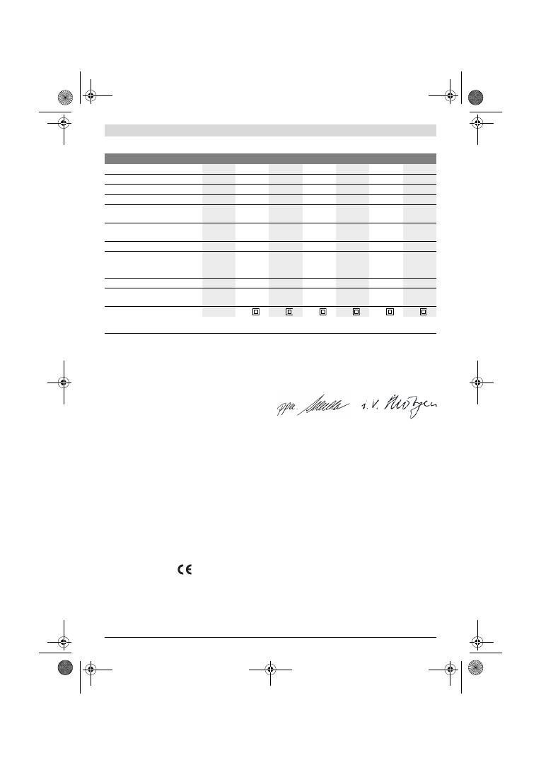
80
| Česky
1 619 929 J37 | (2.2.12)
Bosch Power Tools
Technická data
Informace o hluku a vibracích
Naměřené hodnoty hluku zjištěny podle EN 60745.
Hodnocená hladina akustického tlaku A stroje činí typicky
76 dB(A). Nepřesnost K=3 dB.
Hladina hluku může při práci překročit 80 dB(A).
Noste ochranu sluchu!
Celkové hodnoty vibrací a
h
(vektorový součet tří os) a
nepřesnost K stanoveny podle EN 60745:
a
h
=4,5 m/s
2
, K=1,5 m/s
2
.
V těchto pokynech uvedená úroveň vibrací byla změřena
podle měřících metod normovaných v EN 60745 a může být
použita pro vzájemné porovnání elektronářadí. Hodí se i pro
předběžný odhad zatížení vibracemi.
Uvedená úroveň vibrací reprezentuje hlavní použití
elektronářadí. Pokud ovšem bude elektronářadí nasazeno pro
jiná použití, s odlišnými nasazovacími nástroji nebo s
nedostatečnou údržbou, může se úroveň vibrací lišit. To může
zatíženi vibracemi po celou pracovní dobu zřetelně zvýšit.
Pro přesný odhad zatížení vibracemi by měly být zohledněny
i doby, v nichž je stroj vypnutý nebo sice běží, ale fakticky není
nasazen. To může zatíženi vibracemi po celou pracovní dobu
zřetelně zredukovat.
Stanovte dodatečná bezpečnostní opatření k ochraně
obsluhy před účinky vibrací jako např.: údržba elektronářadí a
nasazovacích nástrojů, udržování teplých rukou, organizace
pracovních procesů.
Prohlášení o shodě
Prohlašujeme v plné naší zodpovědnosti, že v odstavci
„
Technická data
“
popsaný výrobek je v souladu s
následujícími normami nebo normativními dokumenty:
EN 60745 podle ustanovení směrnic 2011/65/EU,
2004/108/ES, 2006/42/ES.
Technická dokumentace (2006/42/ES) u:
Robert Bosch GmbH, PT/ETM9,
D-70745 Leinfelden-Echterdingen
Robert Bosch GmbH, Power Tools Division
D-70745 Leinfelden-Echterdingen
12.01.2012
Montáž
f
Před každou prací na elektronářadí vytáhněte zástrčku
ze zásuvky.
Odsávání prachu/třísek
f
Prach materiálů jako olovoobsahující nátěry, některé
druhy dřeva, minerálů a kovu mohou být zdraví škodlivé.
Kontakt s prachem nebo vdechnutí mohou vyvolat
alergické reakce a/nebo onemocnění dýchacích cest
obsluhy nebo v blízkosti se nacházejících osob.
Určitý prach jako dubový nebo bukový prach je pokládán
za karcinogenní, zvláště ve spojení s přídavnými látkami
pro ošetření dřeva (chromát, ochranné prostředky na
dřevo). Materiál obsahující azbest smějí opracovávat
pouze specialisté.
–
Pokud možno používejte pro daný materiál vhodné
odsávání prachu.
–
Pečujte o dobré větrání pracovního prostoru.
–
Je doporučeno nosit ochrannou dýchací masku s
třídou filtru P2.
Vibrační bruska
GSS ...
230 A
230 AE
230 AE
280 A
280 AE
280 AE
Objednací číslo
0 601 ...
292 0..
292 7..
292 6..
293 0..
293 7..
293 6..
Prachový box v obsahu dodávky
–
–
z
–
–
z
Předvolba počtu kmitů
–
z
z
–
z
z
Jmenovitý příkon
W
300
300
300
330
330
330
Otáčky naprázdno
min
-1
11000
5500
–
11000
5500
–
11000
11000
5500
–
11000
5500
–
11000
Počet kmitů při volnoběhu
min
-1
22000
11000
–
22000
11000
–
22000
22000
11000
–
22000
11000
–
22000
Průměr oscilační kružnice
mm
2,4
2,4
2,4
2,4
2,4
2,4
Rozměry brusného listu
–
Uchycení na suchý zip
–
Svorkové upnutí
mm
mm
93 x 185
93 x 230
93 x 185
93 x 230
93 x 185
93 x 230
115 x 230
115 x 280
115 x 230
115 x 280
115 x 230
115 x 280
Rozměry brusné desky
mm
92 x 182
92 x 182
92 x 182 114 x 226 114 x 226 114 x 226
Hmotnost podle EPTA-Procedure
01/2003
kg
2,3
2,3
2,3
2,6
2,6
2,6
Třída ochrany
/
II
/
II
/
II
/
II
/
II
/
II
Údaje platí pro jmenovité napětí [U] 230 V. U odlišných napětí a podle země specifických provedení se mohou tyto údaje lišit.
Dbejte prosím objednacího čísla na typovém štítku Vašeho elektronářadí. Obchodní označení jednotlivých elektronářadí se mohou měnit.
Dr. Egbert Schneider
Senior Vice President
Engineering
Dr. Eckerhard Strötgen
Engineering Director
PT/ESI
OBJ_BUCH-426-005.book Page 80 Thursday, February 2, 2012 10:06 AM

Česky |
81
Bosch Power Tools
1 619 929 J37 | (2.2.12)
Dbejte ve Vaší zemi platných předpisů pro opracovávané
materiály.
f
Vyvarujte se usazenin prachu na pracovišti.
Prach se
může lehce vznítit.
Vlastní odsávání pomocí prachového boxu
(viz obr. A1
–
A4)
Před montáží prachového boxu
6
vytáhněte ven plastové
šoupátko
13
. Prachový box
6
nasaďte na výfukové hrdlo
14
až zaskočí. Dbejte na to, aby plastové šoupátko
13
zabíralo do
uchycení
12
.
K vyprázdnění prachového boxu
6
stlačte aretační páčku
15
na straně prachového boxu (
n
). Prachový box vytáhněte
dolů (
o
).
Před otevřením prachového boxu
6
by jste jej měli, jak je
ukázáno na obrázku, oklepat na pevnou podložku kvůli
uvolnění prachu na filtračním prvku.
Uchopte prachový box
6
na uchopovacích prohlubních,
vyklopte filtrační prvek
16
nahoru a prachový box vyprázněte.
Lamely filtračního prvku
16
čistěte pomocí měkkého kartáče.
Externí odsávání (viz obr. B)
Nastrčte odsávací adaptér
17
na výfukové hrdlo
14
. Dbejte
na to, aby aretační páčky odsávacího adaptéru zaskočily. Na
odsávací adaptér
17
může být připojena odsávací hadice s
průměrem 19 mm.
Pro demontáž odsávacího adaptéru
17
stlačte aretační páčky
vzadu k sobě a odsávací adaptér stáhněte.
Vysavač musí být vhodný pro opracovávaný materiál.
Při odsávání obzvlášť zdraví škodlivého, karcinogenního nebo
suchého prachu použijte speciální vysavač.
Výměna brusného listu
Před nasazením nového brusného listu odstraňte z brusné
desky
9
nečistoty a prach, např. štětcem.
Pro zaručení optimálního odsávání dbejte na to, aby děrování
brusného listu souhlasilo s otvory v brusné desce.
Brusné listy se suchým zipem (viz obr. C)
Brusná deska
9
je vybavena tkaninou suchého zipu, pomocí
níž mohou být brusné listy se suchým zipem rychle a
jednoduše upevněny.
Tkaninu suchého zipu brusné desky
9
před nasazením
brusného listu
19
vyklepejte, aby bylo umožněno optimální
přilnutí.
Brusný list
19
přiložte v jedné přímce na jedné straně brusné
desky
9
, poté brusný list položte na brusnou desku a pevně jej
přitlačte.
Pro odejmutí brusného listu
19
jej uchopte na jednom rohu a
stáhněte z brusné desky
9
.
Brusné listy bez suchého zipu (viz obr. D)
Lehce nadzdvihněte upínací třmeny
8
a vyvěste je.
Zaveďte brusný list
19
až na doraz pod otevřenou zadní
svěrnou lištu
10
a brusný list upněte zavěšením upínacího
třmenu
8
.
Položte brusný list
19
natažený na brusnou desku. Zaveďte
druhý konec brusného listu
19
pod otevřenou přední svěrnou
lištu
10
a brusný list upněte zavěšením upínacího třmenu
8
.
Brusné listy bez otvorů, z rolí popř. z metrového zboží můžete
pro odsávání prachu proděrovat děrovacím nástrojem
20
. K
tomu natlačte elektronářadí s namontovaným brusným listem
na děrovací nástroj (viz obr. E).
K odejmutí brusného listu
19
uvolněte upínací třmeny
8
a
brusný list vytáhněte.
Volba brusného listu
Podle opracovávaného materiálu a požadovaného úběru
povrchu jsou k dispozici různé brusné listy:
Výměna brusné desky (viz obr. F)
Brusnou desku
9
lze podle potřeby vyměnit.
Zcela vyšroubujte 6 šroubů
21
ven a brusnou desku
9
odejměte. Nasaďte novou brusnou desku
9
a šrouby opět
utáhněte.
Zvláštní brusné desky
Dodávanou brusnou desku
9
můžete vyměnit za zvláštní
brusné desky, jež jsou k dostání jako příslušenství.
Montáž zvláštní brusné desky se děje adekvátně podle
výměny dodávané brusné desky.
Nasazení a odejmutí příslušných brusných listů se děje
adekvátně podle výměny původních brusných listů.
Prodloužená brusná deska, pravoúhlá, tenká
(GSS 230 A/GSS 230 AE) (viz obr. G)
Použití pravoúhlé, tenké, prodloužené brusné desky
22
Vám
umožní broušení na těžko přístupných místech a úzkých
meziprostorech, jako např. lamely oken a dveří, drážky nebo
za potrubím topných těles a vodovodním potrubím.
Pro montáž pravoúhlé, tenké, prodloužené brusné desky
22
použijte příslušné šrouby
24
.
Zrnitost
40
–
400
K opracování veškerých
dřevěných materiálů
K předbroušení např. drsných,
nehoblovaných trámů a prken
hrubý
40, 60
K rovinnému broušení a ke
srovnání malých nerovností
střední
80, 100, 120
Ke konečnému a jemnému
broušení tvrdého dřeva
jemný
180, 240,
320, 400
40
–
320
K opracování barevných a
lakovaných vrstev popř.
podkladů jako jsou plniva a
tmely
K odbroušení barvy
hrubý
40, 60
K broušení napouštěcích barev
střední
80, 100, 120
Ke konečnému broušení
podkladů pro lakování
jemný
180, 240, 320
OBJ_BUCH-426-005.book Page 81 Thursday, February 2, 2012 10:06 AM
82
| Česky
1 619 929 J37 | (2.2.12)
Bosch Power Tools
Prodloužená brusná deska, trojúhelníková
(GSS 230 A/GSS 230 AE) (viz obr. H)
Použití trojúhelníkové prodloužené brusné desky
26
Vám
umožní broušení v rozích a na hranách.
Jemná brusná deska (bez suchého zipu)
(GSS 230 AE/GSS 280 AE) (viz obr. D)
Při převažujícím používání standardních brusných listů bez
suchého zipu se doporučuje použití jemné brusné desky bez
suchého zipu. Díky jejímu plochému povrchu se docílí
zejména při jemném broušení optimálních výsledků broušení.
Přídavná rukojeť
Přídavná rukojeť
1
umožňuje pohodlnou manipulaci a
optimální rozdělení síly především u vysokého úběru
broušení.
Přídavnou rukojeť
1
upevněte pomocí šroubu
2
na těleso.
Provoz
Uvedení do provozu
f
Dbejte síťového napětí! Napětí zdroje proudu musí
souhlasit s údaji na typovém štítku elektronářadí.
Elektronářadí označené 230 V smí být provozováno i
na 220 V.
Zapnutí – vypnutí
K
uvedení
elektronářadí
do provozu
stlačte spínač
4
a
podržte jej stlačený.
K
aretaci
stlačeného spínače
4
stlačte aretační tlačítko
5
.
K
vypnutí
elektronářadí spínač
4
uvolněte popř. je-li
aretačním tlačítkem
5
zaaretován, spínač
4
krátce stlačte a
potom jej uvolněte.
Předvolba počtu kmitů (GSS 230 AE/GSS 280 AE)
Pomocí nastavovacího kolečka předvolby počtu kmitů
3
můžete předvolit požadovaný počet kmitů i během provozu.
Potřebný počet kmitů je závislý na materiálu a pracovních
podmínkách a lze jej zjistit praktickými zkouškami.
Pracovní pokyny
f
Počkejte, až se stroj zastaví, než jej odložíte.
Výkon úběru při broušení je určen hlavně volbou brusného
listu a též předvoleným počtem kmitů (GSS 230 AE/
GSS 280 AE).
Pouze bezvadné brusné listy dávají dobrý brusný výkon a šetří
elektronářadí.
Dbejte na rovnoměrný přítlak, abyste zvýšili životnost
brusných papírů.
Nadměrné zvýšení přítlaku nevede k vyššímu brusného
výkonu, ale k silnějšímu opotřebení elektronářadí a brusného
listu.
Brusný list, který byl použit pro kov, už nepoužívejte pro jiné
materiály.
Používejte pouze originální brusné příslušenství Bosch.
Údržba a servis
Údržba a čištění
f
Před každou prací na elektronářadí vytáhněte zástrčku
ze zásuvky.
f
Udržujte elektronářadí a větrací otvory čisté, abyste
pracovali dobře a bezpečně.
Je-li nutné nahrazení přívodního kabelu, pak to nechte kvůli
zamezení ohrožení bezpečnosti provést firmou Bosch nebo
autorizovaným servisem pro elektronářadí Bosch.
Pokud dojde i přes pečlivou výrobu a náročné kontroly k
poruše stroje, svěřte provedení opravy autorizovanému
servisnímu středisku pro elektronářadí firmy Bosch.
Při všech dotazech a objednávkách náhradních dílů nezbytně
prosím uvádějte 10-místné objednací číslo podle typového
štítku elektronářadí.
Zákaznická a poradenská služba
Zákaznická služba zodpoví Vaše dotazy k opravě a údržbě
Vašeho výrobku a též k náhradním dílům. Technické výkresy a
informace k náhradním dílům naleznete i na:
www.bosch-pt.com
Tým poradenské služby Bosch Vám rád pomůže při otázkách
ke koupi, používání a nastavení výrobků a příslušenství.
Czech Republic
Robert Bosch odbytová s.r.o.
Bosch Service Center PT
K Vápence 1621/16
692 01 Mikulov
Tel.: +420 (519) 305 700
Fax: +420 (519) 305 705
E-Mail: servis.naradi@cz.bosch.com
www.bosch.cz
Zpracování odpadů
Elektronářadí, příslušenství a obaly by měly být dodány k
opětovnému zhodnocení nepoškozujícímu životní prostředí.
Neodhazujte elektronářadí do domovního odpadu!
Pouze pro země EU:
Podle evropské směrnice 2002/96/ES o
starých elektrických a elektronických
zařízeních a jejím prosazení v národních
zákonech musí být neupotřebitelné
elektronářadí rozebrané shromážděno a
dodáno k opětovnému zhodnocení nepo-
škozujícímu životní prostředí.
Změny vyhrazeny.
OBJ_BUCH-426-005.book Page 82 Thursday, February 2, 2012 10:06 AM
Slovensky |
83
Bosch Power Tools
1 619 929 J37 | (2.2.12)
Slovensky
Bezpečnostné pokyny
Všeobecné výstražné upozornenia a
bezpečnostné pokyny
Prečítajte si všetky Výstražné upozornenia
a bezpečnostné pokyny.
Zanedbanie
dodržiavania Výstražných upozornení a pokynov uvedených v
nasledujúcom texte môže mať za následok zásah elektrickým
prúdom, spôsobiť požiar a/alebo ťažké poranenie.
Tieto Výstražné upozornenia a bezpečnostné pokyny
starostlivo uschovajte na budúce použitie.
Pojem
„
ručné elektrické náradie
“
používaný v nasledujúcom
texte sa vzťahuje na ručné elektrické náradie napájané zo
siete (s prívodnou šnúrou) a na ručné elektrické náradie
napájané akumulátorovou batériou (bez prívodnej šnúry).
Bezpečnosť na pracovisku
f
Pracovisko vždy udržiavajte čisté a dobre osvetlené.
Neporiadok a neosvetlené priestory pracoviska môžu mať
za následok pracovné úrazy.
f
Týmto náradím nepracujte v prostredí ohrozenom
výbuchom, v ktorom sa nachádzajú horľavé kvapaliny,
plyny alebo horľavý prach.
Ručné elektrické náradie
vytvára iskry, ktoré by mohli prach alebo pary zapáliť.
f
Nedovoľte deťom a iným nepovolaným osobám, aby sa
počas používania ručného elektrického náradia
zdržiavali v blízkosti pracoviska.
Pri odpútaní pozornosti
zo strany inej osoby môžete stratiť kontrolu nad náradím.
Elektrická bezpečnosť
f
Zástrčka prívodnej šnúry ručného elektrického náradia
musí pasovať do použitej zásuvky. Zástrčku v žiadnom
prípade nijako nemeňte. S uzemneným elektrickým
náradím nepoužívajte ani žiadne zástrčkové adaptéry.
Nezmenené zástrčky a vhodné zásuvky znižujú riziko
zásahu elektrickým prúdom.
f
Vyhýbajte sa telesnému kontaktu s uzemnenými
povrchovými plochami, ako sú napr. rúry, vykurovacie
telesá, sporáky a chladničky.
Keby by bolo Vaše telo
uzemnené, hrozí zvýšené riziko zásahu elektrickým
prúdom.
f
Chráňte elektrické náradie pred účinkami dažďa a
vlhkosti.
Vniknutie vody do ručného elektrického náradia
zvyšuje riziko zásahu elektrickým prúdom.
f
Nepoužívajte prívodnú šnúru mimo určený účel na
nosenie ručného elektrického náradia, ani na jeho
zavesenie a zástrčku nevyberajte zo zásuvky ťahaním
za prívodnú šnúru. Zabezpečte, aby sa sieťová šnúra
nedostala do blízkosti horúceho telesa, ani do kontaktu
s olejom, s ostrými hranami alebo pohybujúcimi sa sú-
čiastkami ručného elektrického náradia.
Poškodené
alebo zauzlené prívodné šnúry zvyšujú riziko zásahu
elektrickým prúdom.
f
Keď pracujete s ručným elektrickým náradím vonku,
používajte len také predlžovacie káble, ktoré sú
schválené aj na používanie vo vonkajších priestoroch.
Použitie predlžovacieho kábla, ktorý je vhodný na
používanie vo vonkajšom prostredí, znižuje riziko zásahu
elektrickým prúdom.
f
Ak sa nedá vyhnúť použitiu ručného elektrického
náradia vo vlhkom prostredí, použite ochranný spínač
pri poruchových prúdoch.
Použitie ochranného spínača
pri poruchových prúdoch znižuje riziko zásahu elektrickým
prúdom.
Bezpečnosť osôb
f
Buďte ostražitý, sústreďte sa na to, čo robíte a k práci
s ručným elektrickým náradím pristupujte s rozumom.
Nepracujte s ručným elektrickým náradím nikdy vtedy,
keď ste unavený, alebo keď ste pod vplyvom drog,
alkoholu alebo liekov.
Malý okamih nepozornosti môže
mať pri používaní náradia za následok vážne poranenia.
f
Noste osobné ochranné pomôcky a používajte vždy
ochranné okuliare.
Nosenie osobných ochranných
pomôcok, ako je ochranná dýchacia maska, bezpečnostná
pracovná obuv. ochranná prilba alebo chrániče sluchu,
podľa druhu ručného elektrického náradia a spôsobu jeho
použitia znižujú riziko poranenia.
f
Vyhýbajte sa neúmyselnému uvedeniu ručného
elektrického náradia do činnosti. Pred zasunutím
zástrčky do zásuvky a/alebo pred pripojením
akumulátora, pred chytením alebo prenášaním ruč-
ného elektrického náradia sa vždy presvedčte sa, či je
ručné elektrické náradie vypnuté.
Ak budete mať pri pre-
nášaní ručného elektrického náradia prst na vypínači,
alebo ak ručné elektrické náradie pripojíte na elektrickú
sieť zapnuté, môže to mať za následok nehodu.
f
Skôr ako náradie zapnete, odstráňte z neho
nastavovacie náradie alebo kľúče na skrutky.
Nastavovací nástroj alebo kľúč, ktorý sa nachádza v
rotujúcej časti ručného elektrického náradia, môže
spôsobiť vážne poranenia osôb.
f
Vyhýbajte sa abnormálnym polohám tela. Zabezpečte
si pevný postoj, a neprestajne udržiavajte rovnováhu.
Takto budete môcť ručné elektrické náradie v
neočakávaných situáciách lepšie kontrolovať.
f
Pri práci noste vhodný pracovný odev. Nenoste široké
odevy a nemajte na sebe šperky. Vyvarujte sa toho, aby
sa Vaše vlasy, odev a rukavice dostali do blízkosti
rotujúcich súčiastok náradia.
Voľný odev, dlhé vlasy
alebo šperky môžu byť zachytené rotujúcimi časťami
ručného elektrického náradia.
f
Ak sa dá na ručné elektrické náradie namontovať
odsávacie zariadenie a zariadenie na zachytávanie
prachu, presvedčte sa, či sú dobre pripojené a správne
používané.
Používanie odsávacieho zariadenia a
zariadenia na zachytávanie prachu znižuje riziko ohrozenia
zdravia prachom.
Starostlivé používanie ručného elektrického náradia a
manipulácia s ním
f
Ručné elektrické náradie nikdy nepreťažujte.
Používajte také elektrické náradie, ktoré je určené pre
daný druh práce.
Pomocou vhodného ručného
elektrického náradia budete pracovať lepšie a bezpeč-
nejšie v uvedenom rozsahu výkonu náradia.
POZOR
OBJ_BUCH-426-005.book Page 83 Thursday, February 2, 2012 10:06 AM
84
| Slovensky
1 619 929 J37 | (2.2.12)
Bosch Power Tools
f
Nepoužívajte nikdy také ručné elektrické náradie,
ktoré má pokazený vypínač.
Náradie, ktoré sa už nedá
zapnúť alebo vypnúť, je nebezpečné a treba ho zveriť do
opravy odborníkovi.
f
Skôr ako začnete náradie nastavovať alebo
prestavovať, vymieňať príslušenstvo alebo skôr, ako
odložíte náradie, vždy vytiahnite zástrčku sieťovej
šnúry zo zásuvky.
Toto preventívne opatrenie zabraňuje
neúmyselnému spusteniu ručného elektrického náradia.
f
Nepoužívané ručné elektrické náradie uschovávajte
tak, aby bolo mimo dosahu detí. Nedovoľte používať
pneumatické náradie osobám, ktoré s ním nie sú
dôverne oboznámené, alebo ktoré si neprečítali tieto
Pokyny.
Ručné elektrické náradie je nebezpečné vtedy,
keď ho používajú neskúsené osoby.
f
Ručné elektrické náradie starostlivo ošetrujte.
Kontrolujte, či pohyblivé súčiastky bezchybne fungujú
alebo či neblokujú, či nie sú zlomené alebo poškodené
niektoré súčiastky, ktoré by mohli negatívne
ovplyvňovať správne fungovanie ručného elektrického
náradia. Pred použitím náradia dajte poškodené
súčiastky vymeniť.
Veľa nehôd bolo spôsobených
nedostatočnou údržbou elektrického náradia.
f
Rezné nástroje udržiavajte ostré a čisté.
Starostlivo
ošetrované rezné nástroje s ostrými reznými hranami majú
menšiu tendenciu k zablokovaniu a ľahšie sa dajú viesť.
f
Používajte ručné elektrické náradie, príslušenstvo,
nastavovacie nástroje a pod. podľa týchto výstražných
upozornení a bezpečnostných pokynov. Pri práci
zohľadnite konkrétne pracovné podmienky a činnosť,
ktorú budete vykonávať.
Používanie ručného
elektrického náradia na iný účel ako na predpísané
použitie môže viesť k nebezpečným situáciám.
Servisné práce
f
Ručné elektrické náradie dávajte opravovať len
kvalifikovanému personálu, ktorý používa originálne
náhradné súčiastky.
Tým sa zabezpečí, že bezpečnosť
náradia zostane zachovaná.
Bezpečnostné pokyny pre brúsky
f
Používajte ručné elektrické náradie len na brúsenie
nasucho.
Vniknutie vody do ručného elektrického náradia
zvyšuje riziko zásahu elektrickým prúdom.
f
Pozor, nebezpečenstvo požiaru! Vyhýbajte sa
prehrievaniu brúsených obrobkov a brúsky. Zásobník
na prach vždy pred prestávkou v práci vyprázdnite.
Brúsny prach v odsávacom vrecku, mikrofiltri alebo v
papierovom vrecu (prípadne vo filtračnom vrecku resp.
filtri vysávača) sa môže za nepriaznivých okolností ako
napr. pri odletovaní iskier kovov, sám od seba zapáliť.
Osobitné nebezpečenstvo hrozí najmä vtedy, ak je
zmiešaný so zvyškami laku, polyuretánu alebo s inými
chemickými látkami a brúsený materiál je po dlhej práci
horúci.
f
Pri práci držte ručné elektrické náradie pevne oboma
rukami a zabezpečte si stabilný postoj.
Pomocou dvoch
rúk sa ručné elektrické náradie ovláda bezpečnejšie.
f
Zabezpečte obrobok.
Obrobok upnutý pomocou
upínacieho zariadenia alebo zveráka je bezpečnejší ako
obrobok pridržiavaný rukou.
Popis produktu a výkonu
Prečítajte si všetky Výstražné upozornenia
a bezpečnostné pokyny.
Zanedbanie
dodržiavania Výstražných upozornení a
pokynov uvedených v nasledujúcom texte
môže mať za následok zásah elektrickým
prúdom, spôsobiť požiar a/alebo ťažké
poranenie.
Vyklopte si láskavo vyklápaciu stranu s obrázkami produktu a
nechajte si ju vyklopenú po celý čas, keď čítate tento Návod
na používanie.
Používanie podľa určenia
Náradie je určené na brúsenie nasucho a na leštenie dreva,
plastov, stierkovacej hmoty ako aj lakovaných povrchov.
Vyobrazené komponenty
Číslovanie jednotlivých komponentov sa vzťahuje na
vyobrazenie elektrického náradia na grafickej strane tohto
Návodu na používanie.
1
Prídavná rukoväť (izolovaná plocha rukoväte)*
2
Skrutka pre prídavnú rukoväť*
3
Nastavovacie koliesko predvoľby frekvencie vibrácií
(GSS 230 AE/GSS 280 AE)
4
Vypínač
5
Aretačné tlačidlo vypínača
6
Kompletný zásobník na prach (Microfilter System)*
7
Kľúč na skrutky s vnútorným šesťhranom
8
Upínací strmienok
9
Brúsna doska
10
Upevňovacia lišta
11
Rukoväť (izolovaná plocha rukoväte)
12
Držiak zásobníka na prach*
13
Plastový posúvač
14
Odsávací nátrubok
15
Aretačná páčka zásobníka na prach*
16
Filtračná vložka (Microfilter System)*
17
Odsávací adaptér*
18
Odsávacia hadica*
19
Brúsny list*
20
Dierkovač*
21
Skrutky pre brúsnu dosku
22
Brúsna doska tenká, predĺžená*
23
Brúsny list, predĺžený*
24
Skrutky na predĺženú brúsnu dosku*
25
Brúsny list, trojuholníkový*
26
Brúsna doska trojuholníková, predĺžená*
*Zobrazené alebo popísané príslušenstvo nepatrí celé do
základnej výbavy produktu. Kompletné príslušenstvo nájdete v
našom programe príslušenstva.
OBJ_BUCH-426-005.book Page 84 Thursday, February 2, 2012 10:06 AM
Slovensky |
85
Bosch Power Tools
1 619 929 J37 | (2.2.12)
Technické údaje
Informácia o hlučnosti/vibráciách
Namerané hodnoty hluku zistené podľa normy EN 60745.
Hodnotená hladina akustického tlaku A tohto náradia je
typicky 76 dB(A). Nepresnosť merania K=3 dB.
Hladina hluku môže pri práci dosahovať hodnotu nad
80 dB(A).
Používajte chrániče sluchu!
Celkové hodnoty vibrácií a
h
(suma vektorov troch smerov) a
nepresnosť merania K zisťované podľa normy EN 60745:
a
h
=4,5 m/s
2
, K=1,5 m/s
2
.
Úroveň kmitov uvedená v týchto pokynoch bola nameraná
podľa meracieho postupu uvedeného v norme EN 60745 a
možno ju používať na vzájomné porovnávanie rôznych typov
ručného elektrického náradia medzi sebou. Hodí sa aj na
predbežný odhad zaťaženia vibráciami.
Uvedená hladina vibrácií reprezentuje hlavné druhy
používania tohto ručného elektrického náradia. Avšak v takých
prípadoch, keď sa toto ručné elektrické náradie použije na iné
druhy použitia, s odlišnými pracovnými nástrojmi alebo sa
podrobuje nedostatočnej údržbe, môže sa hladina zaťaženia
vibráciami od týchto hodnôt odlišovať. To môže výrazne zvýšiť
zaťaženie vibráciami počas celej pracovnej doby.
Na presný odhad zaťaženia vibráciami počas určitého časového
úseku práce s náradím treba zohľadniť doby, počas ktorých je
ručné elektrické náradie vypnuté alebo doby, keď náradie síce
beží, ale v skutočnosti sa nepoužíva. To môže výrazne
redukovať zaťaženie vibráciami počas celej pracovnej doby.
Na ochranu osoby pracujúcej s náradím pred účinkami
zaťaženia vibráciami vykonajte ďalšie bezpečnostné
opatrenia, ako sú napríklad: údržba ručného elektrického
náradia a používaných pracovných nástrojov, zabezpečenie
zachovania teploty rúk, organizácia jednotlivých pracovných
úkonov.
Vyhlásenie o konformite
Na vlastnú zodpovednosť vyhlasujeme, že dole popísaný
výrobok
„
Technické údaje
“
sa zhoduje s nasledujúcimi
normami alebo normatívnymi dokumentami: EN 60745
podľa ustanovení smerníc 2011/65/EÚ, 2004/108/ES,
2006/42/ES.
Súbor technickej dokumentácie (2006/42/ES)
sa nachádza u:
Robert Bosch GmbH, PT/ETM9,
D-70745 Leinfelden-Echterdingen
Robert Bosch GmbH, Power Tools Division
D-70745 Leinfelden-Echterdingen
12.01.2012
Montáž
f
Pred každou prácou na ručnom elektrickom náradí
vytiahnite zástrčku náradia zo zásuvky.
Odsávanie prachu a triesok
f
Prach z niektorých materiálov, napr. z náterov
obsahujúcich olovo, z niektorých druhov tvrdého dreva,
minerálov a kovov môže byť zdraviu škodlivý. Kontakt s
takýmto prachom alebo jeho vdychovanie môže vyvolávať
alergické reakcie a/alebo spôsobiť ochorenie dýchacích
ciest pracovníka, prípadne osôb, ktoré sa nachádzajú v
blízkosti pracoviska.
Vibračná brúska
GSS ...
230 A
230 AE
230 AE
280 A
280 AE
280 AE
Vecné číslo
0 601 ...
292 0..
292 7..
292 6..
293 0..
293 7..
293 6..
Zásobník na prach je súčasťou
základnej výbavy
–
–
z
–
–
z
Predvoľba frekvencie kmitov
–
z
z
–
z
z
Menovitý príkon
W
300
300
300
330
330
330
Počet voľnobežných obrátok
min
-1
11000
5500
–
11000
5500
–
11000
11000
5500
–
11000
5500
–
11000
Počet voľnobežných kmitov
min
-1
22000
11000
–
22000
11000
–
22000
22000
11000
–
22000
11000
–
22000
Priemer kmitov
mm
2,4
2,4
2,4
2,4
2,4
2,4
Rozmery brúsneho listu
–
Velkronové upínanie
–
Strmeňové upínanie
mm
mm
93 x 185
93 x 230
93 x 185
93 x 230
93 x 185
93 x 230
115 x 230
115 x 280
115 x 230
115 x 280
115 x 230
115 x 280
Rozmery brúsnej dosky
mm
92 x 182
92 x 182
92 x 182 114 x 226 114 x 226 114 x 226
Hmotnosť podľa EPTA-Procedure
01/2003
kg
2,3
2,3
2,3
2,6
2,6
2,6
Trieda ochrany
/
II
/
II
/
II
/
II
/
II
/
II
Tieto údaje platia pre menovité napätie [U] 230 V. V takých prípadoch, keď má napätie odlišné hodnoty a pri vyhotoveniach, ktoré sú špecifické pre
niektorú krajinu, sa môžu tieto údaje odlišovať.
Všimnite si láskavo vecné číslo na typovom štítku svojho ručného elektrického náradia. Obchodné názvy jednotlivých produktov sa môžu odlišovať.
Dr. Egbert Schneider
Senior Vice President
Engineering
Dr. Eckerhard Strötgen
Engineering Director
PT/ESI
OBJ_BUCH-426-005.book Page 85 Thursday, February 2, 2012 10:06 AM

86
| Slovensky
1 619 929 J37 | (2.2.12)
Bosch Power Tools
Určité druhy prachu, napr. prach z dubového alebo z
bukového dreva, sa považujú za rakovinotvorné, a to
predovšetkým spolu s ďalšími materiálmi, ktoré sa
používajú pri spracovávaní dreva (chromitan, chemické
prostriedky na ochranu dreva). Materiál, ktorý obsahuje
azbest, smú opracovávať len špeciálne vyškolení
pracovníci.
–
Používajte podľa možnosti také odsávanie, ktoré je pre
daný materiál vhodné.
–
Postarajte sa o dobré vetranie svojho pracoviska.
–
Odporúčame Vám používať ochrannú dýchaciu masku
s filtrom triedy P2.
Dodržiavajte aj predpisy vlastnej krajiny týkajúce sa
konkrétneho obrábaného materiálu.
f
Vyhýbajte sa usadzovaniu prachu na Vašom
pracovisku.
Viaceré druhy prachu sa môžu ľahko vznieť.
Vlastné odsávanie so zásobníkom na prach
(pozri obrázok A1
–
A4)
Pred montážou zásobníka na prach
6
vytiahnite plastový
posúvač
13
. Zásobník na prach
6
nasaďte na odsávací
nátrubok
14
tak, aby zaskočil. Dávajte pritom pozor na to, aby
plastový posúvač
13
siahal až dovnútra držiaka
12
.
Na vyprázdnenie zásobníka na prach
6
stlačte aretačnú páčku
15
na bočnej strane zásobníka na prach (
n
). Potiahnite
zásobník na prach smerom dole (
o
).
Pred otvorením zásobníka na prach
6
by ste mali zásobník na
prach vyklepať o pevnú podložku podľa obrázka, aby ste
uvoľnili prach z filtračnej vložky.
Uchopte zásobník na prach
6
za uchopovaciu priehlbinu,
vyklopte filtračnú vložku
16
smerom hore a vyprázdnite
zásobník na prach. Lamely filtračnej vložky vyčistite
16
pomocou jemnej kefky.
Externé odsávanie (pozri obrázok B)
Nasuňte odsávací adaptér
17
na odsávací nátrubok
14
.
Dávajte pozor na to, aby aretačná páka odsávacieho adaptéra
vždy zaskočila. Na odsávací adaptér
17
sa dá namontovať
odsávacia hadica s priemerom 19 mm.
Pri demontáži odsávacieho adaptéra
17
stlačte vzadu
aretačnú páku adaptéra a adaptér demontujte.
Vysávač musí byť vhodný pre daný druh opracovávaného
materiálu.
Pri odsávaní materiálov mimoriadne ohrozujúcich zdravie,
rakovinotvorných alebo suchých prachov používajte
špeciálny vysávač.
Výmena brúsneho listu
Pred nasadením nového brúsneho listu odstráňte nečistotu a
prach z brúsnej dosky
9
, napríklad pomocou štetca.
Na zabezpečenie optimálneho odsávania dajte pozor na to,
aby sa výrezy na brúsnom liste prekrývali s otvormi na brúsnej
doske.
Brúsne listy s velkronovým upínaním (pozri obrázok C)
Brúsna doska
9
je vybavená velkronovou tkaninou, aby sa dali
brúsne listy rýchlo a jednoducho upínať.
Vyklepte velkronovú tkaninu brúsnej dosky
9
pred každým
zakladaním brúsneho listu
19
, aby ste umožnili optimálne
upnutie listu.
Priložte brúsny list
19
na jednej strane zarovno s brúsnou
doskou
9
, potom pílový list založte na brúsnu dosku do
správnej polohy a dobre ho zatlačte.
Pri demontáži brúsneho listu
19
ho uchopte za niektorý hrot a
stiahnite ho z brúsnej dosky
9
.
Brúsne listy bez velkronového upínania (pozri obrázok D)
Nadvihnite trochu upínací strmienok
8
a vyveste ho.
Zaveďte brúsny list
19
až na doraz pod otvorenú zadnú
upevňovaciu lištu
10
a upnite brúsny list zavesením
upínacieho strmienka
8
.
Brúsny list
19
položte na brúsnu dosku v napnutom stave.
Zaveďte druhý koniec brúsneho listu
19
pod otvorenú prednú
upevňovaciu lištu
10
a upnite brúsny list zavesením
upínacieho strmienka
8
.
Brúsny listy s nevyrazenými otvormi, napr. z kotúčov, resp.
metráže môžete na odsávanie pripraviť pomocou dierkovača
20
. Pritlačte na tento účel ručné elektrické náradie s
namontovaným brúsnym listom na dierkovač
(pozri obrázok E).
Ak chcete demontovať brúsny list
19
uvoľnite upínací
strmienok
8
a brúsny list vyberte.
Výber brúsneho listu
Podľa druhu obrábaného materiálu a požadovaného úberu
povrchu obrobku sú k dispozícii rozličné brúsne listy:
Zrnitosť
40
–
400
Na obrábanie všetkých
drevených materiálov
Na predbrúsenie napr. drsných
nehobľovaných hranolov a dosák
hrubý
40, 60
Na rovinné brúsenie a na
zarovnávanie drobných
nerovností
stredný 80, 100, 120
Na dokončovacie a jemné
brúsenie tvrdého dreva
jemný
180, 240,
320, 400
40
–
320
Na obrábanie farebných a
lakovaných povrchov resp.
základných úprav napríklad
plnivami alebo tmelom
Na obrúsenie farby
hrubý
40, 60
Na brúsenie základnej farby
stredný 80, 100, 120
Na dokončovacie brúsenie pri
lakovaní
jemný
180, 240, 320
OBJ_BUCH-426-005.book Page 86 Thursday, February 2, 2012 10:06 AM

Slovensky |
87
Bosch Power Tools
1 619 929 J37 | (2.2.12)
Výmena brúsnej dosky (pozri obrázok F)
Brúsna doska
9
sa dá v prípade potreby vymeniť.
Vyskrutkujte úplne 6 skrutiek
21
a demontujte brúsnu dosku
9
. Založte novú brúsnu dosku
9
a skrutky opäť utiahnite.
Špeciálne brúsne dosky
Dodanú brúsnu dosku
9
môžete nahradiť špeciálnou brúsnou
doskou, ktorá sa dá zakúpiť ako zvláštne príslušenstvo.
Montáž špeciálnej brúsnej dosky sa uskutoční podľa popisu
Výmeny dodanej brúsnej dosky.
Montáž a demontáž príslušného brúsneho listu sa vykonáva
podľa popisu výmeny originálneho brúsneho listu.
Predĺžená brúsna doska, pravouhlá, tenká
(GSS 230 A/GSS 230 AE) (pozri obrázok G)
Používanie pravouhlej tenkej predĺženej brúsnej dosky
22
Vám umožňuje brúsenie na ťažko prístupných miestach a v
úzkych priestoroch, napríklad obrusovanie okenných a
dverových lamiel, drážok alebo prácu za vykurovacími
telesami a za vodovodným potrubím.
Na montáž pravouhlej tenkej predĺženej brúsnej dosky
22
používajte príslušné skrutky
24
.
Predĺžená brúsna doska, trojuholníková
(GSS 230 A/GSS 230 AE) (pozri obrázok H)
Používanie trojuholníkovej predĺženej brúsnej dosky
26
Vám
umožňuje brúsenie vnútorných rohov a vonkajších hrán.
Brúsna doska na jemné brúsenie (bez velkronového
upínania) (GSS 230 AE/GSS 280 AE) (pozri obrázok D)
Ak sa používajú väčšinou štandardné brúsne listy bez
velkronového upínania, odporúčame používanie brúsnej
dosky na jemné brúsenie bez velkronového upínania. Vďaka
svojmu rovinnému povrchu sa dajú dosiahnuť optimálne
výsledky brúsenia predovšetkým pri jemnom brúsení.
Prídavná rukoväť
Prídavná rukoväť
1
umožňuje pohodlnú pracovnú
manipuláciu a optimálne rozdeľovanie sily predovšetkým pri
veľkom úbere.
Prídavnú rukoväť
1
upevnite pomocou skrutky
2
na teleso
náradia.
Prevádzka
Uvedenie do prevádzky
f
Všimnite si napätie siete! Napätie zdroja prúdu musí
mať hodnotu zhodnú s údajmi na typovom štítku
ručného elektrického náradia. Výrobky označené pre
napätie 230 V sa smú používať aj s napätím 220 V.
Zapínanie/vypínanie
Na
zapnutie
ručného elektrického náradia stlačte vypínač
4
a
držte ho stlačený.
Na
aretáciu
stlačeného vypínača
4
stlačte aretačné tlačidlo
5
.
Ak chcete ručné elektrické náradie
vypnúť
uvoľnite vypínač
4
a v takom prípade, ak je zaaretovaný aretačným tlačidlom
5
,
stlačte vypínač
4
na okamih a potom ho znova uvoľnite.
Predvoľba frekvencie vibrácií (GSS 230 AE/GSS 280 AE)
Pomocou nastavovacieho kolieska predvoľby frekvencie
vibrácií
3
môžete nastaviť požadovanú frekvenciu vibrácií aj
počas prevádzky ručného elektrického náradia.
Potrebná hodnota frekvencie vibrácií závisí od materiálu a
pracovných podmienok a dá sa zistiť praktickou skúškou.
Pokyny na používanie
f
Počkajte na úplné zastavenie ručného elektrického
náradia, až potom ho odložte.
Úber je pri brúsení do značnej miery závislý od výberu
vhodného brúsneho listu ako aj od nastavenej frekvencie
vibrácií (GSS 230 AE/GSS 280 AE).
Dobrý brúsny výkon a šetrenie ručného elektrického náradia
môžete dosiahnuť len pomocou bezchybných brúsnych
listov.
Dbajte na rovnomerný prítlak, aby ste zvýšili životnosť
brúsnych listov.
Nadmierne zvýšenie prítlaku nemá za následok zvýšenie
brúsneho výkonu, vedie len k zvýšenému opotrebovaniu
ručného elektrického náradia a brúsneho listu.
Brúsny list, ktorý ste použili na brúsenie kovového materiálu,
už nepoužívajte na brúsenie iných materiálov.
Používajte na brúsenie len originálne príslušenstvo Bosch.
Údržba a servis
Údržba a čistenie
f
Pred každou prácou na ručnom elektrickom náradí
vytiahnite zástrčku náradia zo zásuvky.
f
Ručné elektrické náradie a jeho vetracie štrbiny
udržiavajte vždy v čistote, aby ste mohli pracovať
kvalitne a bezpečne.
Ak je potrebná výmena prívodnej šnúry, musí ju vykonať firma
Bosch alebo niektoré autorizované servisné stredisko
ručného elektrického náradia Bosch, aby sa zabránilo
ohrozeniu bezpečnosti používateľa náradia.
Ak by prístroj napriek starostlivej výrobe a kontrole predsa len
prestal niekedy fungovať, treba dať opravu vykonať
autorizovanej servisnej opravovni elektrického náradia
Bosch.
Pri všetkých dopytoch a objednávkach náhradných súčiastok
uvádzajte bezpodmienečne 10-miestne vecné číslo uvedené
na typovom štítku výrobku.
Servisné stredisko a poradenská služba pre
zákazníkov
Servisné stredisko Vám odpovie na otázky týkajúce sa opravy
a údržby Vášho produktu ako aj náhradných súčiastok.
Rozložené obrázky a informácie k náhradným súčiastkam
nájdete aj na web-stránke:
www.bosch-pt.com
Tím poradenskej služby pre zákazníkov Bosch Vám rád
pomôže aj pri problémoch týkajúcich sa kúpy a nastavenia
produktov a príslušenstva.
OBJ_BUCH-426-005.book Page 87 Thursday, February 2, 2012 10:06 AM
88
| Magyar
1 619 929 J37 | (2.2.12)
Bosch Power Tools
Slovakia
Tel.: +421 (02) 48 703 800
Fax: +421 (02) 48 703 801
E-Mail: servis.naradia@sk.bosch.com
www.bosch.sk
Likvidácia
Ručné elektrické náradie, príslušenstvo a obal treba dať na
recykláciu šetriacu životné prostredie.
Neodhadzujte ručné elektrické náradie do komunálneho
odpadu!
Len pre krajiny EÚ:
Podľa Európskej smernice 2002/96/ES o
starých elektrických a elektronických
výrobkoch a podľa jej aplikácií v národnom
práve sa musia už nepoužiteľné elektrické
produkty zbierať separovane a dať na
recykláciu zodpovedajúcu ochrane
životného prostredia.
Zmeny vyhradené.
Magyar
Biztonsági előírások
Általános biztonsági előírások az elektromos
kéziszerszámokhoz
Olvassa el az összes
biztonsági figyelmeztetést
és előírást.
A következőkben leírt előírások betartásának
elmulasztása áramütésekhez, tűzhöz és/vagy súlyos testi
sérülésekhez vezethet.
Kérjük a későbbi használatra gondosan őrizze meg ezeket
az előírásokat.
Az alább alkalmazott
„
elektromos kéziszerszám
”
fogalom a
hálózati elektromos kéziszerszámokat (hálózati csatlakozó
kábellel) és az akkumulátoros elektromos kéziszerszámokat
(hálózati csatlakozó kábel nélkül) foglalja magában.
Munkahelyi biztonság
f
Tartsa tisztán és jól megvilágított állapotban a
munkahelyét.
A rendetlenség és a megvilágítatlan
munkaterület balesetekhez vezethet.
f
Ne dolgozzon a berendezéssel olyan
robbanásveszélyes környezetben, ahol éghető
folyadékok, gázok vagy porok vannak.
Az elektromos
kéziszerszámok szikrákat keltenek, amelyek a port vagy a
gőzöket meggyújthatják.
f
Tartsa távol a gyerekeket és az idegen személyeket a
munkahelytől, ha az elektromos kéziszerszámot
használja.
Ha elvonják a figyelmét, elvesztheti az uralmát a
berendezés felett.
Elektromos biztonsági előírások
f
A készülék csatlakozó dugójának bele kell illeszkednie
a dugaszolóaljzatba. A csatlakozó dugót semmilyen
módon sem szabad megváltoztatni. Védőföldeléssel
ellátott készülékekkel kapcsolatban ne használjon
csatlakozó adaptert.
A változtatás nélküli csatlakozó
dugók és a megfelelő dugaszoló aljzatok csökkentik az
áramütés kockázatát.
f
Kerülje el a földelt felületek, mint például csövek,
fűtőtestek, kályhák és hűtőgépek megérintését.
Az
áramütési veszély megnövekszik, ha a teste le van földelve.
f
Tartsa távol az elektromos kéziszerszámot az esőtől
vagy nedvességtől.
Ha víz hatol be egy elektromos
kéziszerszámba, ez megnöveli az áramütés veszélyét.
f
Ne használja a kábelt a rendeltetésétől eltérő célokra,
vagyis a szerszámot soha ne hordozza vagy akassza fel
a kábelnél fogva, és sohase húzza ki a hálózati csat-
lakozó dugót a kábelnél fogva. Tartsa távol a kábelt
hőforrásoktól, olajtól, éles élektől és sarkoktól és
mozgó gépalkatrészektől.
Egy megrongálódott vagy cso-
mókkal teli kábel megnöveli az áramütés veszélyét.
f
Ha egy elektromos kéziszerszámmal a szabad ég alatt
dolgozik, csak szabadban való használatra
engedélyezett hosszabbítót használjon.
A szabadban
való használatra engedélyezett hosszabbító használata
csökkenti az áramütés veszélyét.
f
Ha nem lehet elkerülni az elektromos kéziszerszám
nedves környezetben való használatát, alkalmazzon
egy hibaáram-védőkapcsolót.
Egy hibaáram-védőkap-
csoló alkalmazása csökkenti az áramütés kockázatát.
Személyi biztonság
f
Munka közben mindig figyeljen, ügyeljen arra, amit
csinál és meggondoltan dolgozzon az elektromos
kéziszerszámmal. Ha fáradt, ha kábítószerek vagy
alkohol hatása alatt áll, vagy orvosságokat vett be, ne
használja a berendezést.
Egy pillanatnyi figyelmetlenség
a szerszám használata közben komoly sérülésekhez
vezethet.
f
Viseljen személyi védőfelszerelést és mindig viseljen
védőszemüveget.
A személyi védőfelszerelések, mint
porvédő álarc, csúszásbiztos védőcipő, védősapka és fül-
védő használata az elektromos kéziszerszám használata
jellegének megfelelően csökkenti a személyi sérülések
kockázatát.
f
Kerülje el a készülék akaratlan üzembe helyezését.
Győződjön meg arról, hogy az elektromos
kéziszerszám ki van kapcsolva, mielőtt bedugná a
csatlakozó dugót a dugaszolóaljzatba, csatlakoztatná
az akkumulátor-csomagot, és mielőtt felvenné és vinni
kezdené az elektromos kéziszerszámot.
Ha az
elektromos kéziszerszám felemelése közben az ujját a
kapcsolón tartja, vagy ha a készüléket bekapcsolt
állapotban csatlakoztatja az áramforráshoz, ez balese-
tekhez vezethet.
FIGYELMEZTETÉS
OBJ_BUCH-426-005.book Page 88 Thursday, February 2, 2012 10:06 AM
Magyar |
89
Bosch Power Tools
1 619 929 J37 | (2.2.12)
f
Az elektromos kéziszerszám bekapcsolása előtt
okvetlenül távolítsa el a beállítószerszámokat vagy
csavarkulcsokat.
Az elektromos kéziszerszám forgó
részeiben felejtett beállítószerszám vagy csavarkulcs
sérüléseket okozhat.
f
Ne becsülje túl önmagát. Kerülje el a normálistól eltérő
testtartást, ügyeljen arra, hogy mindig biztosan álljon
és az egyensúlyát megtartsa.
Így az elektromos
kéziszerszám felett váratlan helyzetekben is jobban tud
uralkodni.
f
Viseljen megfelelő ruhát. Ne viseljen bő ruhát vagy
ékszereket. Tartsa távol a haját, a ruháját és a
kesztyűjét a mozgó részektől.
A bő ruhát, az ékszereket
és a hosszú hajat a mozgó alkatrészek magukkal
ránthatják.
f
Ha az elektromos kéziszerszámra fel lehet szerelni a
por elszívásához és összegyűjtéséhez szükséges
berendezéseket, ellenőrizze, hogy azok megfelelő
módon hozzá vannak kapcsolva a készülékhez és ren-
deltetésüknek megfelelően működnek.
A porgyűjtő
berendezések használata csökkenti a munka során
keletkező por veszélyes hatását.
Az elektromos kéziszerszámok gondos kezelése és
használata
f
Ne terhelje túl a berendezést. A munkájához csak az
arra szolgáló elektromos kéziszerszámot használja.
Egy alkalmas elektromos kéziszerszámmal a megadott
teljesítménytartományon belül jobban és
biztonságosabban lehet dolgozni.
f
Ne használjon olyan elektromos kéziszerszámot,
amelynek a kapcsolója elromlott.
Egy olyan elektromos
kéziszerszám, amelyet nem lehet sem be-, sem kikapcsol-
ni, veszélyes és meg kell javíttatni.
f
Húzza ki a csatlakozó dugót a dugaszolóaljzatból
és/vagy az akkumulátor-csomagot az elektromos
kéziszerszámból, mielőtt az elektromos
kéziszerszámon beállítási munkákat végez,
tartozékokat cserél vagy a szerszámot tárolásra
elteszi.
Ez az elővigyázatossági intézkedés meggátolja a
szerszám akaratlan üzembe helyezését.
f
A használaton kívüli elektromos kéziszerszámokat
olyan helyen tárolja, ahol azokhoz gyerekek nem
férhetnek hozzá. Ne hagyja, hogy olyan személyek
használják az elektromos kéziszerszámot, akik nem
ismerik a szerszámot, vagy nem olvasták el ezt az
útmutatót.
Az elektromos kéziszerszámok veszélyesek,
ha azokat gyakorlatlan személyek használják.
f
A készüléket gondosan ápolja. Ellenőrizze, hogy a
mozgó alkatrészek kifogástalanul működnek-e,
nincsenek-e beszorulva, és nincsenek-e eltörve vagy
megrongálódva olyan alkatrészek, amelyek hatással
lehetnek az elektromos kéziszerszám működésére. A
berendezés megrongálódott részeit a készülék
használata előtt javíttassa meg.
Sok olyan baleset
történik, amelyet az elektromos kéziszerszám nem
kielégítő karbantartására lehet visszavezetni.
f
Tartsa tisztán és éles állapotban a vágószerszámokat.
Az éles vágóélekkel rendelkező és gondosan ápolt vágó-
szerszámok ritkábban ékelődnek be és azokat könnyebben
lehet vezetni és irányítani.
f
Az elektromos kéziszerszámokat, tartozékokat,
betétszerszámokat stb. csak ezen előírásoknak és az
adott készüléktípusra vonatkozó kezelési
utasításoknak megfelelően használja. Vegye
figyelembe a munkafeltételeket és a kivitelezendő
munka sajátosságait.
Az elektromos kéziszerszám
eredeti rendeltetésétől eltérő célokra való alkalmazása
veszélyes helyzetekhez vezethet.
Szervíz-ellenőrzés
f
Az elektromos kéziszerszámot csak szakképzett
személyzet csak eredeti pótalkatrészek
felhasználásával javíthatja.
Ez biztosítja, hogy az
elektromos kéziszerszám biztonságos maradjon.
Biztonsági előírások a csiszológépekhez
f
Az elektromos kéziszerszámot csak száraz csiszolásra
használja.
Ha víz hatol be egy elektromos kéziszerszámba,
ez megnöveli az áramütés veszélyét.
f
Vigyázat, tűzveszély! Előzze meg a csiszolásra kerülő
munkadarab és a csiszológép túlmelegedését. A
munkaszünetekben mindig ürítse ki a porgyűjtő
tartályt.
A porzsákban mikroszűrőben, papírzsákban
(vagy a szűrőzsákban, illetve a porszívó szűrőjében)
található, a csiszolás közben keletkeztt por hátrányos
körülmények között (például szétrepülő szikrák) magától
meggyulladhat. Ez a veszély még tovább növekszik, ha a
csiszolás során keletkező porban lakk, poliuretán, vagy
más vegyszer is található és a megmunkálásra kerülő
munkadarab egy hosszabb időtartamú csiszolás során
felforrósodott.
f
A munka során mindig mindkét kezével tartsa az
elektromos kéziszerszámot és gondoskodjon arról,
hogy szilárd, biztos alapon álljon.
Az elektromos
kéziszerszámot két kézzel biztosabban lehet vezetni.
f
A megmunkálásra kerülő munkadarabot megfelelően
rögzítse.
Egy befogó szerkezettel vagy satuval rögzített
munkadarab biztonságosabban van rögzítve, mintha csak
a kezével tartaná.
A termék és alkalmazási lehetőségei
leírása
Olvassa el az összes biztonsági
figyelmeztetést és előírást.
A következőkben leírt előírások betartásának
elmulasztása áramütésekhez, tűzhöz és/vagy
súlyos testi sérülésekhez vezethet.
Kérjük hajtsa ki a kihajtható ábrás oldalt, és hagyja így
kihajtva, miközben ezt a kezelési útmutatót olvassa.
Rendeltetésszerű használat
A készülék fa, műanyag, spatulyázó massza és lakkozott
felületek száraz csiszolására szolgál.
OBJ_BUCH-426-005.book Page 89 Thursday, February 2, 2012 10:06 AM
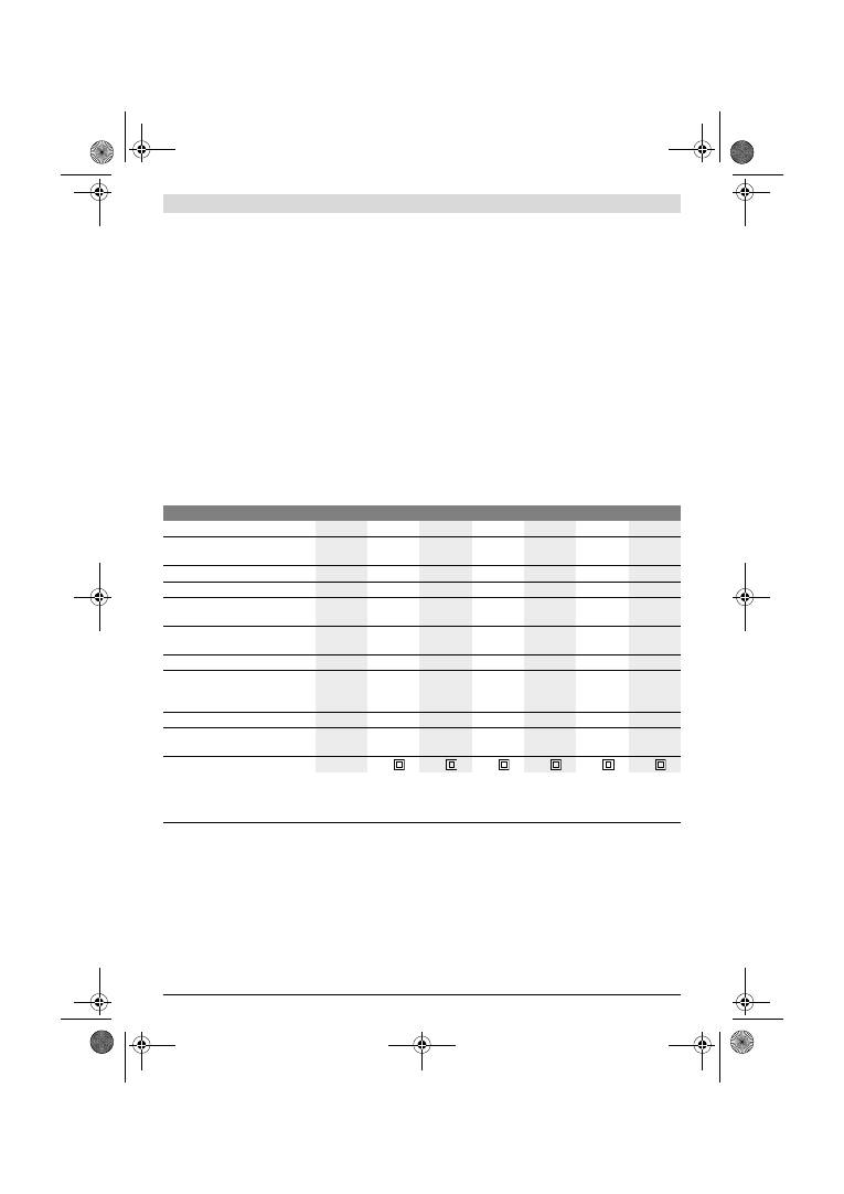
90
| Magyar
1 619 929 J37 | (2.2.12)
Bosch Power Tools
Az ábrázolásra kerülő komponensek
A készülék ábrázolásra kerülő komponenseinek
sorszámozása az elektromos kéziszerszámnak az ábra-
oldalon található képére vonatkozik.
1
Pótfogantyú (szigetelt fogantyú-felület)*
2
Csavar a pótfogantyú számára*
3
Rezgésszám-előválasztó szabályozókerék
(GSS 230 AE/GSS 280 AE)
4
Be-/kikapcsoló
5
Be-/kikapcsoló rögzítőgombja
6
Porgyűjtő doboz, komplett (Microfilter System)*
7
Imbuszkulcs
8
Szorítókengyelek
9
Csiszolótalp
10
Kapocsléc
11
Fogantyú (szigetelt fogantyú-felület)
12
Porgyűjtő doboz tartó*
13
Műanyag tolóka
14
Kifúvó csőcsonk
15
Porgyűjtő doboz reteszelőkar*
16
Szűrőbetét (Microfilter System)*
17
Elszívó-adapter*
18
Elszívó tömlő*
19
Csiszolólap*
20
Lyukasztó szerszám*
21
Csavarok a csiszolólemezhez
22
Vékony, meghosszabbított csiszolótalp*
23
Meghosszabbított csiszolótalp*
24
Csavarok a meghosszabbított csiszolótalphoz*
25
Csiszolólap, háromszög alakú*
26
Háromszög alakú, meghosszabbított csiszolótalp*
*A képeken látható vagy a szövegben leírt tartozékok részben nem
tartoznak a standard szállítmányhoz. Tartozékprogramunkban
valamennyi tartozék megtalálható.
Műszaki adatok
Zaj és vibráció értékek
A zajmérési eredmények az EN 60745 szabványnak
megfelelően kerültek meghatározásra.
A készülék A-értékelésű tipikus hangnyomásszintje 76 dB(A).
Bizonytalanság K=3 dB.
A munkavégzés alatti zajszint túllépheti a 80 dB(A)-t.
Viseljen fülvédőt!
a
h
rezgési összértékek (a három irány vektorösszege) és K
bizonytalanság az EN 60745 szabvány szerint:
a
h
=4,5 m/s
2
, K=1,5 m/s
2
.
Az ezen előírásokban megadott rezgésszint az EN 60745
szabványban rögzített mérési módszerrel került
meghatározásra és az elektromos kéziszerszámok
összehasonlítására ez az érték felhasználható. Ez az érték a
rezgési terhelés ideiglenes becslésére is alkalmas.
A megadott rezgésszint az elektromos kéziszerszám fő
alkalmazási területein való használat során fellépő érték. Ha
az elektromos kéziszerszámot más alkalmazásokra, eltérő
betétszerszámokkal vagy nem kielégítő karbantartás mellett
használják, a rezgésszint a fenti értéktől eltérhet. Ez az egész
munkaidőre vonatkozó rezgési terhelést lényegesen
megnövelheti.
Rezgőcsiszoló
GSS ...
230 A
230 AE
230 AE
280 A
280 AE
280 AE
Cikkszám
0 601 ...
292 0..
292 7..
292 6..
293 0..
293 7..
293 6..
A porgyűjtő doboz a szállítmány
része
–
–
z
–
–
z
Rezgésszám előválasztás
–
z
z
–
z
z
Névleges felvett teljesítmény
W
300
300
300
330
330
330
Üresjárati fordulatszám
perc
-1
11000
5500
–
11000
5500
–
11000
11000
5500
–
11000
5500
–
11000
Üresjárati rezgésszám
perc
-1
22000
11000
–
22000
11000
–
22000
22000
11000
–
22000
11000
–
22000
Rezgési kör átmérője
mm
2,4
2,4
2,4
2,4
2,4
2,4
Csiszolólap méretek
–
Tépőzáras rögzítés
–
Szorítókengyeles rögzítés
mm
mm
93 x 185
93 x 230
93 x 185
93 x 230
93 x 185
93 x 230
115 x 230
115 x 280
115 x 230
115 x 280
115 x 230
115 x 280
Csiszolólemez méretek
mm
92 x 182
92 x 182
92 x 182 114 x 226 114 x 226 114 x 226
Súly az „EPTA-Procedure 01/2003”
(2003/01 EPTA-eljárás) szerint
kg
2,3
2,3
2,3
2,6
2,6
2,6
Érintésvédelmi osztály
/
II
/
II
/
II
/
II
/
II
/
II
Az adatok [U] = 230 V névleges feszültségre vonatkoznak. Ettől eltérő feszültségek esetén és az egyes országok számára készült különleges
kivitelekben ezek az adatok változhatnak.
Kérjük vegye figyelembe az elektromos kéziszerszáma típustábláján található cikkszámot. Egyes elektromos kéziszerszámoknak több különböző
kereskedelmi megnevezése is lehet.
OBJ_BUCH-426-005.book Page 90 Thursday, February 2, 2012 10:06 AM
Magyar |
91
Bosch Power Tools
1 619 929 J37 | (2.2.12)
A rezgési terhelés pontos megbecsüléséhez figyelembe kell
venni azokat az időszakokat is, amikor a berendezés
kikapcsolt állapotban van, vagy amikor be van ugyan
kapcsolva, de nem kerül ténylegesen használatra. Ez az egész
munkaidőre vonatkozó rezgési terhelést lényegesen
csökkentheti.
Hozzon kiegészítő biztonsági intézkedéseket a kezelőnek a
rezgések hatása elleni védelmére, például: Az elektromos
kéziszerszám és a betétszerszámok karbantartása, a kezek
melegen tartása, a munkamenetek megszervezése.
Megfelelőségi nyilatkozat
Egyedüli felelőséggel kijelentjük, hogy a
„
Műszaki adatok
”
alatt leírt termék megfelel a következő szabványoknak, illetve
irányadó dokumentumoknak: EN 60745 a 2011/65/EU,
2004/108/EK, 2006/42/EK irányelveknek megfelelően.
A műszaki dokumentációja (2006/42/EK) a következő helyen
található:
Robert Bosch GmbH, PT/ETM9,
D-70745 Leinfelden-Echterdingen
Robert Bosch GmbH, Power Tools Division
D-70745 Leinfelden-Echterdingen
12.01.2012
Összeszerelés
f
Az elektromos kéziszerszámon végzendő bármely
munka megkezdése előtt húzza ki a csatlakozó dugót a
dugaszolóaljzatból.
Por- és forgácselszívás
f
Az ólomtartalmú festékrétegek, egyes fafajták, ásványok
és fémek pora egészségkárosító hatású lehet. A poroknak
a kezelő vagy a közelben tartózkodó személyek által
történő megérintése vagy belégzése allergikus reakciók-
hoz és/vagy a légutak megbetegedését vonhatja maga
után.
Egyes faporok, például tölgy- és bükkfaporok rákkeltő
hatásúak, főleg ha a faanyag kezeléséhez más anyagok is
vannak bennük (kromát, favédő vegyszerek). A
készülékkel azbesztet tartalmazó anyagokat csak
szakembereknek szabad megmunkálniuk.
–
A lehetőségek szerint használjon az anyagnak
megfelelő porelszívást.
–
Gondoskodjon a munkahely jó szellőztetéséről.
–
Ehhez a munkához célszerű egy P2 szűrőosztályú
porvédő álarcot használni.
A feldolgozásra kerülő anyagokkal kapcsolatban tartsa be
az adott országban érvényes előírásokat.
f
Gondoskodjon arról, hogy a munkahelyén ne
gyűlhessen össze por.
A porok könnyen
meggyulladhatnak.
Saját porelszívás porgyűjtő dobozzal
(lásd az A1
–
A4 ábrát)
A
6
porgyűjtő doboz beszerelése előtt húzza ki a
13
műanyag
tolókát. Dugja fel a
6
porgyűjtő dobozt a
14
kifúvó csonkra,
amíg az be nem pattan a helyére. Ügyeljen arra, hogy a
13
műanyag tolóka bekapcsolódjon a
12
tartóba.
A
6
porgyűjtő doboz kiürítéséhez nyomja meg a
15
reteszelőkart a porgyűjtő doboz oldalán (
n
). Húzza le
lefelé a porgyűjtő dobozt (
o
).
A
6
porgyűjtő doboz kinyítása előtt az ábrán látható módon
ütögesse ki a porgyűjtő dobozt egy szilárd alapon, hogy a por
leváljon a szűrőbetétről.
Fogja meg a
6
porgyűjtő dobozt a bemélyedésnél fogva,
hajtsa fel a
16
szűrőbetétet és ürítse ki a porgyűjtő dobozt.
Tisztítsa meg a
16
szűrőbetét lamelláit egy puha kefével.
Külső porelszívás (lásd a „B” ábrát)
Dugja rá a
17
elszívó adaptert a
14
kifúvó csőcsonkra.
Ügyeljen arra, hogy az elszívó adapter reteszelőkarjai
bepattanjanak a rögzített helyzetbe. A
17
elszívó adapterhez
egy 19 mm átmérőjű elszívó tömlőt lehet csatlakoztatni.
A
17
elszívó adapter leszereléséshez nyomja össze hátul
annak reteszelőkarjait és húzza le az elszívó adaptert.
A porszívónak alkalmasnak kell lennie a megmunkálásra
kerülő anyagból keletkező por elszívására.
Az egészségre különösen ártalmas, rákkeltő hatású vagy
száraz porok elszívásához egy speciálisan erre a célra gyártott
porszívót kell használni.
A csiszolólap kicserélése
Egy új csiszolólap felhelyezése előtt távolítson el minden
szennyeződést és port a
9
csiszolótalpról, erre például egy
ecsetet lehet használni.
Az optimális porelszívás biztosítására a csiszolólap
felszerelésekor ügyeljen arra, hogy a csiszolótalp és a
csiszolólap nyílásai egybeessenek.
Tépőzáras rögzítésű csiszolólapok (lásd a „C” ábrát)
A
9
csiszolótalp egy tépőzáras szövettel van ellátva, amelyen
a tépőzáras rögzítéssel ellátott csiszolólapokat gyorsan és
egyszerűen lehet rögzíteni.
Ütögesse ki a
9
csiszolótalp tépőzáras szövetét, mielőtt
felhelyezné arra a
19
csiszolólapot, hogy az optimálisan
rátapadjon a csiszolótalpra.
Tegye rá a
19
csiszolólapot a
9
csiszolólemez egyik oldalára,
azzal egy szintben, majd helyezze rá és erősen nyomja rá a
csiszolólapot a csiszolólemezre.
A
19
csiszolólap levételéhez fogja meg annak egyik sarkát és
húzza le a
9
csiszolótalpról.
Tépőzáras rögzítés nélküli csiszolólapok
(lásd a „D” ábrát)
Kissé emelje fel a
8
szorítókengyeleket, majd akassza ki
azokat.
Vezesse be ütközésig a
19
a csiszolólapot a kinyitott
10
hátsó
szorítóléc alá és a
8
szorítókengyel beakasztásával feszítse ki
a csiszolólapot.
Dr. Egbert Schneider
Senior Vice President
Engineering
Dr. Eckerhard Strötgen
Engineering Director
PT/ESI
OBJ_BUCH-426-005.book Page 91 Thursday, February 2, 2012 10:06 AM
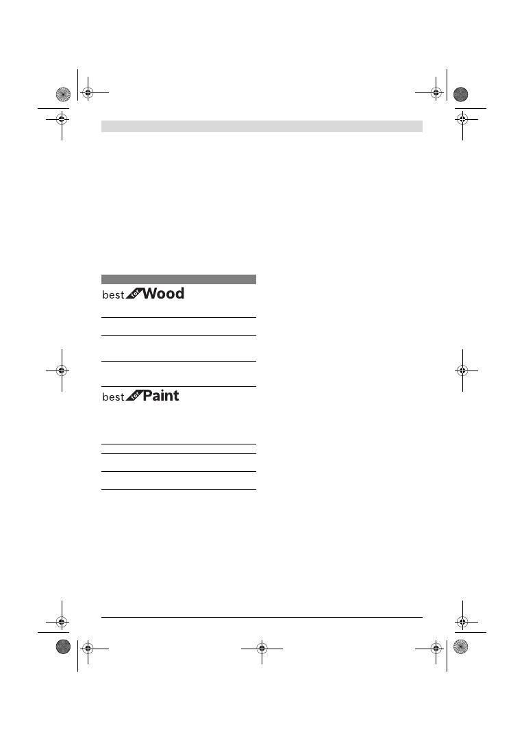
92
| Magyar
1 619 929 J37 | (2.2.12)
Bosch Power Tools
Helyezze rá a
19
csiszolólapot feszesen a csiszolótalpra.
Vezesse át a
19
a csiszolólap másik végét a kinyitott
10
első
szorítóléc alatt és a
8
szorítókengyel beakasztásával feszítse
ki a csiszolólapot.
A lyukakkal el nem látott csiszolópapírokat (például a
tekercsalakban, vagy méterenként vásárolható
csiszolópapírfajtákat) a porelszívás biztosítására a lyukasztó
szerszámmal
20
ki lehet lyukasztani. Ehhez nyomja rá az
elektromos kéziszerszámot az arra felszerelt csiszolólappal a
lyukasztó szerszámra (lásd az „E” ábrát).
A
19
csiszolólap levételéhez oldja ki a
8
szorítókengyelt és
húzza ki a csiszolólapot.
A csiszolólap kiválasztása
A megmunkálásra kerülő anyagnak és a felület kívánt
lemunkálási mélységének megfelelően különböző
csiszolólapok állnak rendelkezésre:
A csiszolótalp kicserélése (lásd az
„
F
”
ábrát)
A
9
csiszolólemezt szükség esetén ki lehet cserélni.
Ehhez csavarja ki teljesen a 6 db
21
csavart és vegye le a
9
csiszolólemezt. Tegye fel az új
9
csiszolólemezt és ismét
húzza meg szorosra a csavarokat.
Különleges csiszolólapok
A készülékkel szállított
9
csiszolólapot ki lehet cserélni egy
tartozékként kapható különleges csiszolólapra.
A különleges csiszolólapot a készülékkel szállított csiszolólap
kicserélésének megfelelően kell felszerelni.
A mindenkori csiszolólapot a készülékkel szállított csiszolólap
fel- és leszerelésének megfelelően kell fel-, illeve leszerelni.
Vékony, meghosszabbított, négyszögletes csiszolótalp
(GSS 230 A/GSS 230 AE) (lásd a
„
G
”
ábrát)
A
22
négyszögletes, vékony, meghosszabbított
csiszolótalppal nehezen hozzáférhető és szűk helyeken,
például ajtó- és ablaklécek, hornyok között, főtőtestek bordái
és vízvezetékcsövek kanyarulatai körül is dolgozhat.
A
22
négyszögletes, vékony, meghosszabbított csiszolótapl
felszereléséhez használja az ahhoz tartozó
24
csavarokat.
Meghosszabbított, háromszög alakú csiszolótalp
(GSS 230 A/GSS 230 AE) (lásd a
„
H
”
ábrát)
A
26
háromszög alakú meghosszabbított csiszolótalppal
éleken és sarkokon is végezhet csiszolási munkát.
Finom csiszolótalp (tépőzáras rögzítés nélkül)
(GSS 230 AE/GSS 280 AE) (lásd a „D” ábrát)
Ha a munka túlnyomó részében standard, tépőzár nélküli
csiszolólapokat használ, akkor célszerű ezekhez a tépőzár
nélküli finom csiszolótalpat használni. Ezek sima talpfelülete
révén főleg a finom csiszolásnál optimális eredményeket
lehet elérni.
Pótfogantyú
Az
1
pótfogantyú kényelmes kezelést, optimális erőelosztást
és mindenek előtt magas lemunkálási teljesítményt tesz
lehetővé.
Csavarozza rá az
1
pótfogantyút a
2
csavarral a házra.
Üzemeltetés
Üzembe helyezés
f
Ügyeljen a helyes hálózati feszültségre! Az áramforrás
feszültségének meg kell egyeznie az elektromos
kéziszerszám típustábláján található adatokkal. A
230 V-os berendezéseket 220 V hálózati feszültségről
is szabad üzemeltetni.
Be- és kikapcsolás
Az elektromos kéziszerszám
üzembe helyezéséhez
nyomja
be és tartsa benyomva a
4
be-/kikapcsolót.
A benyomott
4
be-/kikapcsoló
reteszeléséhez
nyomja be
az
5
rögzítőgombot.
Az elektromos kéziszerszám
kikapcsolásához
engedje el
a
4
be-/kikapcsolót, illetve, ha az az
5
reteszelőgombbal
reteszelve van, nyomja be rövid időre a
4
be-/kikapcsolót,
majd engedje el azt.
A rezgésszám előválasztása (GSS 230 AE/GSS 280 AE)
A
3
rezgésszám előválasztó szabályozókerékkel üzemelő
készüléken is be lehet állítani a rezgésszámot.
A szükséges rezgésszám a megmunkálásra kerülő anyagtól és
a munka körülményeitől függ és egy gyakorlati próbával
meghatározható.
Szemcsenagyság
40
–
400
Bármilyen faanyag
megmunkálásához
Durva, gyalulatlan gerendák és
lapok előzetes csiszolásához
durva
40, 60
Síkra csiszoláshoz és kisebb
egyenetlenségek
kiegyenlítéséhez
közepes 80, 100, 120
Keményfa anyagok
készrecsiszolásához és
finomcsiszolásához
finom
180, 240,
320, 400
40
–
320
Festék és lakkrétegek és
alapozó rétegek, mint például
spatulyázó massza és
töltőanyagok
megmunkálásához
Festékrétegek lecsiszolásához
durva
40, 60
Alapozó festékréteg simára
csiszolásához
közepes 80, 100, 120
Az alapozó rétegek végleges
csiszolásához a lakkozás előtt
finom
180, 240, 320
OBJ_BUCH-426-005.book Page 92 Thursday, February 2, 2012 10:06 AM
Ðóññêèé |
93
Bosch Power Tools
1 619 929 J37 | (2.2.12)
Munkavégzési tanácsok
f
Várja meg, amíg az elektromos kéziszerszám teljesen
leáll, mielőtt letenné.
A csiszolás során a lehordási teljesítményt lényegében a
csiszolópapír kiválasztása és az előzetesen kiválasztott
(GSS 230 AE/GSS 280 AE) rezgésszám határozza meg.
Jó csiszolási teljesítményt az elektromos kéziszerszámot
kímélő használat mellett csak kifogástalan csiszolólapok
alkalmazásával lehet elérni.
Ügyeljen arra, hogy a berendezést egyenletes nyomással
vezesse; így a csiszolólapok élettartartama is megnövekszik.
Túl nagy nyomástól nem a lehordási teljesítmény növekszik,
hanem csak a csiszolólap és az elektromos kéziszerszám
használódik el gyorsabban.
Ha egy csiszolólapot egyszer már valamilyen
fém megmunkálására használt, azt más anyagok
megmunkálására ne használja.
Csak eredeti Bosch gyártmányú csiszoló tartozékokat
használjon.
Karbantartás és szerviz
Karbantartás és tisztítás
f
Az elektromos kéziszerszámon végzendő bármely
munka megkezdése előtt húzza ki a csatlakozó dugót a
dugaszolóaljzatból.
f
Tartsa mindig tisztán az elektromos kéziszerszámot és
annak szellőzőnyílásait, hogy jól és biztonságosan
dolgozhasson.
Ha a csatlakozó vezetéket ki kell cserélni, akkor a cserével
csak a magát a Bosch céget, vagy egy Bosch elektromos
kéziszerszám-műhely ügyfélszolgálatát szabad megbízni,
nehogy a biztonságra veszélyes szituáció lépjen fel.
Ha az elektromos kéziszerszám a gondos gyártási és
ellenőrzési eljárás ellenére egyszer mégis meghibásodna,
akkor a javítással csak Bosch elektromos kéziszerszám-
műhely ügyfélszolgálatát szabad megbízni.
Ha kérdései vannak, vagy pótalkatrészeket akar megrendelni,
okvetlenül adja meg az elektromos kéziszerszám
típustábláján található 10-jegyű cikkszámot.
Vevőszolgálat és tanácsadás
A vevőszolgálat a terméke javításával és karbantartásával,
valamint a pótalkatrészekkel kapcsolatos kérdésekre
szívesen válaszol. A tartalékalkatrészekkel kapcsolatos
robbantott ábrák és egyéb információ a következő címen
találhatók:
www.bosch-pt.com
A Bosch Vevőszolgálat szívesen segít Önnek, ha a termékek és
tartozékok vásárlásával, alkalmazásával és beállításával
kapcsolatos kérdései vannak.
Magyarország
Robert Bosch Kft.
1103 Budapest
Gyömrői út. 120.
Tel.: +36 (01) 431-3835
Fax: +36 (01) 431-3888
Eltávolítás
Az elektromos kéziszerszámokat, a tartozékokat és a
csomagolást a környezetvédelmi szempontoknak
megfelelően kell újrafelhasználásra előkészíteni.
Ne dobja ki az elektromos kéziszerszámokat a háztartási
szemétbe!
Csak az EU-tagországok számára:
A használt villamos és elektronikus
berendezésekre vonatkozó 2002/96/EK
sz. Európai Irányelvnek és ennek a
megfelelő országok jogharmonizációjának
megfelelően a már használhatatlan elektro-
mos kéziszerszámokat külön össze kell
gyűjteni és a környezetvédelmi szempontból megfelelő újra
felhasználásra le kell adni.
A változtatások joga fenntartva.
Ðóññêèé
Óêàçàíèÿ ïî áåçîïàñíîñòè
Îáùèå óêàçàíèÿ ïî òåõíèêå áåçîïàñíîñòè äëÿ
ýëåêòðîèíñòðóìåíòîâ
Ïðî÷òèòå âñå óêàçàíèÿ è
èíñòðóêöèè ïî òåõíèêå
áåçîïàñíîñòè.
Íåñîáëþäåíèå óêàçàíèé è èíñòðóêöèé ïî
òåõíèêå áåçîïàñíîñòè ìîæåò ñòàòü ïðè÷èíîé ïîðàæåíèÿ
ýëåêòðè÷åñêèì òîêîì, ïîæàðà è òÿæåëûõ òðàâì.
Ñîõðàíÿéòå ýòè èíñòðóêöèè è óêàçàíèÿ äëÿ áóäóùåãî
èñïîëüçîâàíèÿ.
Èñïîëüçîâàííîå â íàñòîÿùèõ èíñòðóêöèÿõ è óêàçàíèÿõ
ïîíÿòèå «ýëåêòðîèíñòðóìåíò» ðàñïðîñòðàíÿåòñÿ íà
ýëåêòðîèíñòðóìåíò ñ ïèòàíèåì îò ñåòè (ñ ñåòåâûì øíóðîì)
è íà àêêóìóëÿòîðíûé ýëåêòðîèíñòðóìåíò (áåç ñåòåâîãî
øíóðà).
Áåçîïàñíîñòü ðàáî÷åãî ìåñòà
f
Ñîäåðæèòå ðàáî÷åå ìåñòî â ÷èñòîòå è õîðîøî
îñâåùåííûì.
Áåñïîðÿäîê èëè íåîñâåùåííûå ó÷àñòêè
ðàáî÷åãî ìåñòà ìîãóò ïðèâåñòè ê íåñ÷àñòíûì ñëó÷àÿì.
f
Íå ðàáîòàéòå ñ ýòèì ýëåêòðîèíñòðóìåíòîì âî
âçðûâîîïàñíîì ïîìåùåíèè, â êîòîðîì íàõîäÿòñÿ
ãîðþ÷èå æèäêîñòè, âîñïëàìåíÿþùèåñÿ ãàçû èëè
ïûëü.
Ýëåêòðîèíñòðóìåíòû èñêðÿò, ÷òî ìîæåò ïðèâåñòè
ê âîñïëàìåíåíèþ ïûëè èëè ïàðîâ.
f
Âî âðåìÿ ðàáîòû ñ ýëåêòðîèíñòðóìåíòîì íå
äîïóñêàéòå áëèçêî ê Âàøåìó ðàáî÷åìó ìåñòó äåòåé è
ïîñòîðîííèõ ëèö.
Îòâëåêøèñü, Âû ìîæåòå ïîòåðÿòü
êîíòðîëü íàä ýëåêòðîèíñòðóìåíòîì.
Сертификаты соответствия
хранятся по адресу:
ООО «Роберт Бош»
ул. Акад. Королёва, 13, стр. 5
Россия, 129515, Москва
OBJ_BUCH-426-005.book Page 93 Thursday, February 2, 2012 10:06 AM

94
| Ðóññêèé
1 619 929 J37 | (2.2.12)
Bosch Power Tools
Ýëåêòðîáåçîïàñíîñòü
f
Øòåïñåëüíàÿ âèëêà ýëåêòðîèíñòðóìåíòà äîëæíà
ïîäõîäèòü ê øòåïñåëüíîé ðîçåòêå. Íè â êîåì ñëó÷àå
íå èçìåíÿéòå øòåïñåëüíóþ âèëêó. Íå ïðèìåíÿéòå
ïåðåõîäíûå øòåêåðû äëÿ ýëåêòðîèíñòðóìåíòîâ ñ
çàùèòíûì çàçåìëåíèåì.
Íåèçìåíåííûå øòåïñåëüíûå
âèëêè è ïîäõîäÿùèå øòåïñåëüíûå ðîçåòêè ñíèæàþò ðèñê
ïîðàæåíèÿ ýëåêòðîòîêîì.
f
Ïðåäîòâðàùàéòå òåëåñíûé êîíòàêò ñ çàçåìëåííûìè
ïîâåðõíîñòÿìè, êàê òî: ñ òðóáàìè, ýëåìåíòàìè
îòîïëåíèÿ, êóõîííûìè ïëèòàìè è õîëîäèëüíèêàìè.
Ïðè çàçåìëåíèè Âàøåãî òåëà ïîâûøàåòñÿ ðèñê
ïîðàæåíèÿ ýëåêòðîòîêîì.
f
Çàùèùàéòå ýëåêòðîèíñòðóìåíò îò äîæäÿ è ñûðîñòè.
Ïðîíèêíîâåíèå âîäû â ýëåêòðîèíñòðóìåíò ïîâûøàåò
ðèñê ïîðàæåíèÿ ýëåêòðîòîêîì.
f
Íå ðàçðåøàåòñÿ èñïîëüçîâàòü øíóð íå ïî
íàçíà÷åíèþ, íàïðèìåð, äëÿ òðàíñïîðòèðîâêè èëè
ïîäâåñêè ýëåêòðîèíñòðóìåíòà, èëè äëÿ âûòÿãèâàíèÿ
âèëêè èç øòåïñåëüíîé ðîçåòêè. Çàùèùàéòå øíóð îò
âîçäåéñòâèÿ âûñîêèõ òåìïåðàòóð, ìàñëà, îñòðûõ
êðîìîê èëè ïîäâèæíûõ ÷àñòåé ýëåêòðîèíñòðóìåíòà.
Ïîâðåæäåííûé èëè ñïóòàííûé øíóð ïîâûøàåò ðèñê
ïîðàæåíèÿ ýëåêòðîòîêîì.
f
Ïðè ðàáîòå ñ ýëåêòðîèíñòðóìåíòîì ïîä îòêðûòûì
íåáîì ïðèìåíÿéòå ïðèãîäíûå äëÿ ýòîãî êàáåëè-
óäëèíèòåëè.
Ïðèìåíåíèå ïðèãîäíîãî äëÿ ðàáîòû ïîä
îòêðûòûì íåáîì êàáåëÿ-óäëèíèòåëÿ ñíèæàåò ðèñê
ïîðàæåíèÿ ýëåêòðîòîêîì.
f
Åñëè íåâîçìîæíî èçáåæàòü ïðèìåíåíèÿ ýëåêòðî-
èíñòðóìåíòà â ñûðîì ïîìåùåíèè, ïîäêëþ÷àéòå
ýëåêòðîèíñòðóìåíò ÷åðåç óñòðîéñòâî çàùèòíîãî
îòêëþ÷åíèÿ.
Ïðèìåíåíèå óñòðîéñòâà çàùèòíîãî
îòêëþ÷åíèÿ ñíèæàåò ðèñê ýëåêòðè÷åñêîãî ïîðàæåíèÿ.
Áåçîïàñíîñòü ëþäåé
f
Áóäüòå âíèìàòåëüíûìè, ñëåäèòå çà òåì, ÷òî Âû
äåëàåòå, è ïðîäóìàííî íà÷èíàéòå ðàáîòó ñ ýëåêòðî-
èíñòðóìåíòîì. Íå ïîëüçóéòåñü ýëåêòðîèíñòðó-
ìåíòîì â óñòàëîì ñîñòîÿíèè èëè åñëè Âû íàõîäèòåñü
â ñîñòîÿíèè íàðêîòè÷åñêîãî èëè àëêîãîëüíîãî
îïüÿíåíèÿ èëè ïîä âîçäåéñòâèåì ëåêàðñòâ.
Îäèí
ìîìåíò íåâíèìàòåëüíîñòè ïðè ðàáîòå ñ ýëåêòðîèíñòðó-
ìåíòîì ìîæåò ïðèâåñòè ê ñåðüåçíûì òðàâìàì.
f
Ïðèìåíÿéòå ñðåäñòâà èíäèâèäóàëüíîé çàùèòû è
âñåãäà çàùèòíûå î÷êè.
Èñïîëüçîâàíèå ñðåäñòâ
èíäèâèäóàëüíîé çàùèòû, êàê òî: çàùèòíîé ìàñêè, îáóâè
íà íåñêîëüçÿùåé ïîäîøâå, çàùèòíîãî øëåìà èëè
ñðåäñòâ çàùèòû îðãàíîâ ñëóõà,
–
â çàâèñèìîñòè îò âèäà
ðàáîòû ñ ýëåêòðîèíñòðóìåíòîì ñíèæàåò ðèñê ïîëó÷åíèÿ
òðàâì.
f
Ïðåäîòâðàùàéòå íåïðåäíàìåðåííîå âêëþ÷åíèå
ýëåêòðîèíñòðóìåíòà. Ïåðåä ïîäêëþ÷åíèåì
ýëåêòðîèíñòðóìåíòà ê ýëåêòðîïèòàíèþ è/èëè ê àêêó-
ìóëÿòîðó óáåäèòåñü â âûêëþ÷åííîì ñîñòîÿíèè
ýëåêòðîèíñòðóìåíòà.
Óäåðæàíèå ïàëüöà íà
âûêëþ÷àòåëå ïðè òðàíñïîðòèðîâêå ýëåêòðîèíñòðóìåíòà
è ïîäêëþ÷åíèå ê ñåòè ïèòàíèÿ âêëþ÷åííîãî
ýëåêòðîèíñòðóìåíòà ÷ðåâàòî íåñ÷àñòíûìè ñëó÷àÿìè.
f
Óáèðàéòå óñòàíîâî÷íûé èíñòðóìåíò èëè ãàå÷íûå
êëþ÷è äî âêëþ÷åíèÿ ýëåêòðîèíñòðóìåíòà.
Èíñòðóìåíò èëè êëþ÷, íàõîäÿùèéñÿ âî âðàùàþùåéñÿ
÷àñòè ýëåêòðîèíñòðóìåíòà, ìîæåò ïðèâåñòè ê òðàâìàì.
f
Íå ïðèíèìàéòå íååñòåñòâåííîå ïîëîæåíèå êîðïóñà
òåëà. Âñåãäà çàíèìàéòå óñòîé÷èâîå ïîëîæåíèå è
ñîõðàíÿéòå ðàâíîâåñèå.
Áëàãîäàðÿ ýòîìó Âû ìîæåòå
ëó÷øå êîíòðîëèðîâàòü ýëåêòðîèíñòðóìåíò â
íåîæèäàííûõ ñèòóàöèÿõ.
f
Íîñèòå ïîäõîäÿùóþ ðàáî÷óþ îäåæäó. Íå íîñèòå
øèðîêóþ îäåæäó è óêðàøåíèÿ. Äåðæèòå âîëîñû,
îäåæäó è ðóêàâèöû âäàëè îò äâèæóùèõñÿ ÷àñòåé.
Øèðîêàÿ îäåæäà, óêðàøåíèÿ èëè äëèííûå âîëîñû ìîãóò
áûòü çàòÿíóòû âðàùàþùèìèñÿ ÷àñòÿìè.
f
Ïðè íàëè÷èè âîçìîæíîñòè óñòàíîâêè
ïûëåîòñàñûâàþùèõ è ïûëåñáîðíûõ óñòðîéñòâ
ïðîâåðÿéòå èõ ïðèñîåäèíåíèå è ïðàâèëüíîå
èñïîëüçîâàíèå.
Ïðèìåíåíèå ïûëåîòñîñà ìîæåò
ñíèçèòü îïàñíîñòü, ñîçäàâàåìóþ ïûëüþ.
Ïðèìåíåíèå ýëåêòðîèíñòðóìåíòà è îáðàùåíèå ñ íèì
f
Íå ïåðåãðóæàéòå ýëåêòðîèíñòðóìåíò. Èñïîëüçóéòå
äëÿ Âàøåé ðàáîòû ïðåäíàçíà÷åííûé äëÿ ýòîãî
ýëåêòðîèíñòðóìåíò.
Ñ ïîäõîäÿùèì ýëåêòðîèíñòðóìåí-
òîì Âû ðàáîòàåòå ëó÷øå è íàäåæíåå â óêàçàííîì
äèàïàçîíå ìîùíîñòè.
f
Íå ðàáîòàéòå ñ ýëåêòðîèíñòðóìåíòîì ïðè
íåèñïðàâíîì âûêëþ÷àòåëå.
Ýëåêòðîèíñòðóìåíò,
êîòîðûé íå ïîääàåòñÿ âêëþ÷åíèþ èëè âûêëþ÷åíèþ,
îïàñåí è äîëæåí áûòü îòðåìîíòèðîâàí.
f
Äî íà÷àëà íàëàäêè ýëåêòðîèíñòðóìåíòà, ïåðåä
çàìåíîé ïðèíàäëåæíîñòåé è ïðåêðàùåíèåì ðàáîòû
îòêëþ÷àéòå øòåïñåëüíóþ âèëêó îò ðîçåòêè ñåòè
è/èëè âûíüòå àêêóìóëÿòîð.
Ýòà ìåðà ïðåäîñ-
òîðîæíîñòè ïðåäîòâðàùàåò íåïðåäíàìåðåííîå
âêëþ÷åíèå ýëåêòðîèíñòðóìåíòà.
f
Õðàíèòå ýëåêòðîèíñòðóìåíòû â íåäîñòóïíîì äëÿ
äåòåé ìåñòå. Íå ðàçðåøàéòå ïîëüçîâàòüñÿ ýëåêòðî-
èíñòðóìåíòîì ëèöàì, êîòîðûå íå çíàêîìû ñ íèì èëè
íå ÷èòàëè íàñòîÿùèõ èíñòðóêöèé.
Ýëåêòðîèíñòðó-
ìåíòû îïàñíû â ðóêàõ íåîïûòíûõ ëèö.
f
Òùàòåëüíî óõàæèâàéòå çà ýëåêòðîèíñòðóìåíòîì.
Ïðîâåðÿéòå áåçóïðå÷íóþ ôóíêöèþ è õîä
äâèæóùèõñÿ ÷àñòåé ýëåêòðîèíñòðóìåíòà, îòñóòñòâèå
ïîëîìîê èëè ïîâðåæäåíèé, îòðèöàòåëüíî âëèÿþùèõ
íà ôóíêöèþ ýëåêòðîèíñòðóìåíòà. Ïîâðåæäåííûå
÷àñòè äîëæíû áûòü îòðåìîíòèðîâàíû äî èñïîëüçî-
âàíèÿ ýëåêòðîèíñòðóìåíòà.
Ïëîõîå îáñëóæèâàíèå
ýëåêòðîèíñòðóìåíòîâ ÿâëÿåòñÿ ïðè÷èíîé áîëüøîãî
÷èñëà íåñ÷àñòíûõ ñëó÷àåâ.
f
Äåðæèòå ðåæóùèé èíñòðóìåíò â çàòî÷åííîì è
÷èñòîì ñîñòîÿíèè.
Çàáîòëèâî óõîæåííûå ðåæóùèå
èíñòðóìåíòû ñ îñòðûìè ðåæóùèìè êðîìêàìè ðåæå
çàêëèíèâàþòñÿ è èõ ëåã÷å âåñòè.
f
Ïðèìåíÿéòå ýëåêòðîèíñòðóìåíò, ïðèíàäëåæíîñòè,
ðàáî÷èå èíñòðóìåíòû è ò.ï. â ñîîòâåòñòâèè ñ
íàñòîÿùèìè èíñòðóêöèÿìè. Ó÷èòûâàéòå ïðè ýòîì ðà-
áî÷èå óñëîâèÿ è âûïîëíÿåìóþ ðàáîòó.
Èñïîëüçîâàíèå
ýëåêòðîèíñòðóìåíòîâ äëÿ íåïðåäóñìîòðåííûõ ðàáîò
ìîæåò ïðèâåñòè ê îïàñíûì ñèòóàöèÿì.
OBJ_BUCH-426-005.book Page 94 Thursday, February 2, 2012 10:06 AM
Ðóññêèé |
95
Bosch Power Tools
1 619 929 J37 | (2.2.12)
Ñåðâèñ
f
Ðåìîíò Âàøåãî ýëåêòðîèíñòðóìåíòà ïîðó÷àéòå
òîëüêî êâàëèôèöèðîâàííîìó ïåðñîíàëó è òîëüêî ñ
ïðèìåíåíèåì îðèãèíàëüíûõ çàïàñíûõ ÷àñòåé.
Ýòèì
îáåñïå÷èâàåòñÿ áåçîïàñíîñòü ýëåêòðîèíñòðóìåíòà.
Óêàçàíèÿ ïî òåõíèêå áåçîïàñíîñòè äëÿ
øëèôìàøèí
f
Èñïîëüçóéòå íàñòîÿùèé ýëåêòðîèíñòðóìåíò òîëüêî
äëÿ ñóõîãî øëèôîâàíèÿ.
Ïðîíèêíîâåíèå âîäû â
ýëåêòðîèíñòðóìåíò ïîâûøàåò ðèñê ïîðàæåíèÿ
ýëåêòðîòîêîì.
f
Îñòîðîæíî, îïàñíîñòü ïîæàðà! Ïðåäîòâðàùàéòå
ïåðåãðåâ øëèôóåìîãî ìàòåðèàëà è øëèôîâàëüíîé
ìàøèíû. Ïåðåä ïåðåðûâîì â ðàáîòå âñåãäà
îïîðîæíÿéòå ïûëåñáîðíèê.
Øëèôîâàëüíàÿ ïûëü
ìîæåò âîñïëàìåíèòüñÿ â ñáîðíîì ìåøêå, ìèêðî-
ôèëüòðå, áóìàæíîì ìåøêå (â ôèëüòðóþùåì ìåøêå èëè
â ôèëüòðå ïûëåñîñà) ïðè íåáëàãîïðèÿòíûõ óñëîâèÿõ,
íàïðèìåð, ïðè âîçíèêíîâåíèè ñíîïà èñêð ïðè
øëèôîâàíèè ìåòàëëîâ. Îñîáàÿ îïàñíîñòü âîçíèêàåò
ïðè ïåðåìåøèâàíèè ãîðÿ÷åé îò ïðîäîëæèòåëüíîé
ðàáîòû ïûëè îò øëèôîâàíèÿ ñ îñòàòêàìè ëàêà,
ïîëèóðåòàíà èëè äðóãèõ õèìè÷åñêèõ âåùåñòâ.
f
Âñåãäà äåðæèòå ýëåêòðîèíñòðóìåíò âî âðåìÿ ðàáîòû
îáåèìè ðóêàìè, çàíÿâ ïðåäâàðèòåëüíî óñòîé÷èâîå
ïîëîæåíèå.
Äâóìÿ ðóêàìè Âû ðàáîòàåòå áîëåå íàäåæíî
ñ ýëåêòðîèíñòðóìåíòîì.
f
Çàêðåïëÿéòå çàãîòîâêó.
Çàãîòîâêà, óñòàíîâëåííàÿ â
çàæèìíîå ïðèñïîñîáëåíèå èëè â òèñêè, óäåðæèâàåòñÿ
áîëåå íàäåæíî, ÷åì â Âàøåé ðóêå.
Îïèñàíèå ïðîäóêòà è óñëóã
Ïðî÷òèòå âñå óêàçàíèÿ è èíñòðóêöèè ïî
òåõíèêå áåçîïàñíîñòè.
Óïóùåíèÿ â
îòíîøåíèè óêàçàíèé è èíñòðóêöèé ïî
òåõíèêå áåçîïàñíîñòè ìîãóò ñòàòü ïðè÷èíîé
ïîðàæåíèÿ ýëåêòðè÷åñêèì òîêîì, ïîæàðà è
òÿæåëûõ òðàâì.
Ïîæàëóéñòà, îòêðîéòå ðàñêëàäíóþ ñòðàíèöó ñ
èëëþñòðàöèÿìè ýëåêòðîèíñòðóìåíòà è îñòàâëÿéòå åå
îòêðûòîé, ïîêà Âû èçó÷àåòå ðóêîâîäñòâî ïî ýêñïëóàòàöèè.
Ïðèìåíåíèå ïî íàçíà÷åíèþ
Ýëåêòðîèíñòðóìåíò ïðåäíàçíà÷åí äëÿ ñóõîãî øëèôîâàíèÿ
äðåâåñèíû, ñèíòåòè÷åñêèõ ìàòåðèàëîâ, øïàêëåâêè è
ëàêèðîâàííûõ ïîâåðõíîñòåé.
Èçîáðàæåííûå ñîñòàâíûå ÷àñòè
Íóìåðàöèÿ ïðåäñòàâëåííûõ êîìïîíåíòîâ âûïîëíåíà ïî
èçîáðàæåíèþ íà ñòðàíèöå ñ èëëþñòðàöèÿìè.
1
Äîïîëíèòåëüíàÿ ðóêîÿòêà (ñ èçîëèðîâàííîé
ïîâåðõíîñòüþ)*
2
Âèíò äîïîëíèòåëüíîé ðóêîÿòêè*
3
Êîëåñèêî óñòàíîâêè ÷èñëà êîëåáàíèé
(GSS 230 AE/GSS 280 AE)
4
Âûêëþ÷àòåëü
5
Êíîïêà ôèêñèðîâàíèÿ âûêëþ÷àòåëÿ
6
Êîíòåéíåð äëÿ ïûëè â ñáîðå (Microfilter System)*
7
Øåñòèãðàííûé øòèôòîâûé êëþ÷
8
Çàæèìíàÿ ñêîáà
9
Øëèôîâàëüíàÿ ïëèòà
10
Çàæèìíàÿ ïëàíêà
11
Ðóêîÿòêà (ñ èçîëèðîâàííîé ïîâåðõíîñòüþ)
12
Êðåïëåíèÿ áîêñà äëÿ ïûëè*
13
Ïëàñòìàññîâàÿ çàäâèæêà
14
Âûäóâíîé øòóöåð
15
Ðû÷àã ôèêñèðîâàíèÿ êîíòåéíåðà äëÿ ïûëè*
16
Ôèëüòðîýëåìåíò (Microfilter System)*
17
Àäàïòåð îòñàñûâàíèÿ*
18
Øëàíã îòñàñûâàíèÿ*
19
Øëèôîâàëüíàÿ øêóðêà*
20
Äûðîïðîêàëûâàþùèé èíñòðóìåíò*
21
Âèíòû äëÿ øëèôîâàëüíîé ïëèòû
22
Óäëèíåííàÿ, òîíêàÿ, øëèôîâàëüíàÿ ïëèòà*
23
Óäëèíåííûé, øëèôîâàëüíûé ëèñò*
24
Âèíò äëÿ óäëèíåííîé, øëèôîâàëüíîé ïëèòû*
25
Òðåóãîëüíûé, øëèôîâàëüíûé ëèñò*
26
Óäëèíåííàÿ, òðåóãîëüíàÿ, øëèôîâàëüíàÿ ïëèòà*
*Èçîáðàæåííûå èëè îïèñàííûå ïðèíàäëåæíîñòè íå âõîäÿò â
ñòàíäàðòíûé îáúåì ïîñòàâêè. Ïîëíûé àññîðòèìåíò
ïðèíàäëåæíîñòåé Âû íàéäåòå â íàøåé ïðîãðàììå
ïðèíàäëåæíîñòåé.
Òåõíè÷åñêèå äàííûå
Âèáðàöèîííàÿ øëèôîâàëüíàÿ
ìàøèíà
GSS ...
230 A
230 AE
230 AE
280 A
280 AE
280 AE
Òîâàðíûé ¹
0 601 ...
292 0..
292 7..
292 6..
293 0..
293 7..
293 6..
Áîêñ äëÿ ïûëè â êîìïëåêòå
ïîñòàâêè
–
–
z
–
–
z
Íàñòðîéêà ÷àñòîòû êîëåáàíèé
–
z
z
–
z
z
Íîì. ïîòðåáëÿåìàÿ ìîùíîñòü
Âò
300
300
300
330
330
330
Ïàðàìåòðû óêàçàíû äëÿ íîìèíàëüíîãî íàïðÿæåíèÿ [U] 230 Â. Ïðè äðóãèõ çíà÷åíèÿõ íàïðÿæåíèÿ, à òàêæå â ñïåöèôè÷åñêîì äëÿ ñòðàíû
èñïîëíåíèè èíñòðóìåíòà âîçìîæíû èíûå ïàðàìåòðû.
Ïîæàëóéñòà, ó÷èòûâàéòå òîâàðíûé íîìåð íà çàâîäñêîé òàáëè÷êå Âàøåãî ýëåêòðîèíñòðóìåíòà. Òîðãîâûå íàçâàíèÿ îòäåëüíûõ
ýëåêòðîèíñòðóìåíòîâ ìîãóò ðàçëè÷àòüñÿ.
OBJ_BUCH-426-005.book Page 95 Thursday, February 2, 2012 10:06 AM
96
| Ðóññêèé
1 619 929 J37 | (2.2.12)
Bosch Power Tools
Äàííûå ïî øóìó è âèáðàöèè
Óðîâåíü øóìà îïðåäåëåí â ñîîòâåòñòâèè ñ åâðîïåéñêîé
íîðìîé EN 60745.
Èçìåðåííûé A-âçâåøåííûé óðîâåíü çâóêîâîãî äàâëåíèÿ
ýëåêòðîèíñòðóìåíòà ñîñòàâëÿåò, êàê ïðàâèëî, 76 äÁ(À).
Íåäîñòîâåðíîñòü èçìåðåíèÿ Ê=3 äÁ.
Óðîâåíü øóìà íà ðàáî÷åì ìåñòå ìîæåò ïåðåâûøàòü
80 äÁ(À).
Ïîëüçóéòåñü ñðåäñòâàìè çàùèòû îðãàíîâ ñëóõà!
Ñóììàðíàÿ âèáðàöèÿ a
h
(âåêòîðíàÿ ñóììà òðåõ íàïðàâ-
ëåíèé) è ïîãðåøíîñòü K îïðåäåëåíû â ñîîòâåòñòâèè ñ
EN 60745:
a
h
=4,5 ì/ñ
2
, K=1,5 ì/ñ
2
.
Óêàçàííûé â íàñòîÿùèõ èíñòðóêöèÿõ óðîâåíü âèáðàöèè
èçìåðåí ïî ìåòîäèêå èçìåðåíèÿ, ïðîïèñàííîé â ñòàíäàðòå
EN 60745, è ìîæåò áûòü èñïîëüçîâàí äëÿ ñðàâíåíèÿ
ýëåêòðîèíñòðóìåíòîâ. Îí ïðèãîäåí òàêæå äëÿ
ïðåäâàðèòåëüíîé îöåíêè âèáðàöèîííîé íàãðóçêè.
Óðîâåíü âèáðàöèè óêàçàí äëÿ îñíîâíûõ âèäîâ ðàáîòû ñ
ýëåêòðîèíñòðóìåíòîì. Îäíàêî åñëè ýëåêòðîèíñòðóìåíò
áóäåò èñïîëüçîâàí äëÿ âûïîëíåíèÿ äðóãèõ ðàáîò ñ ïðèìå-
íåíèåì ðàáî÷èõ èíñòðóìåíòîâ, íå ïðåäóñìîòðåííûõ
èçãîòîâèòåëåì, èëè òåõíè÷åñêîå îáñëóæèâàíèå íå áóäåò
îòâå÷àòü ïðåäïèñàíèÿì, òî óðîâåíü âèáðàöèè ìîæåò áûòü
èíûì. Ýòî ìîæåò çíà÷èòåëüíî ïîâûñèòü âèáðàöèîííóþ
íàãðóçêó â òå÷åíèå âñåé ïðîäîëæèòåëüíîñòè ðàáîòû.
Äëÿ òî÷íîé îöåíêè âèáðàöèîííîé íàãðóçêè â òå÷åíèå
îïðåäåëåííîãî âðåìåííîãî èíòåðâàëà íóæíî ó÷èòûâàòü
òàêæå è âðåìÿ, êîãäà èíñòðóìåíò âûêëþ÷åí èëè, õîòÿ è
âêëþ÷åí, íî íå íàõîäèòñÿ â ðàáîòå. Ýòî ìîæåò çíà÷èòåëüíî
ñîêðàòèòü íàãðóçêó îò âèáðàöèè â ðàñ÷åòå íà ïîëíîå
ðàáî÷åå âðåìÿ.
Ïðåäóñìîòðèòå äîïîëíèòåëüíûå ìåðû áåçîïàñíîñòè äëÿ
çàùèòû îïåðàòîðà îò âîçäåéñòâèÿ âèáðàöèè, íàïðèìåð:
òåõíè÷åñêîå îáñëóæèâàíèå ýëåêòðîèíñòðóìåíòà è ðàáî÷èõ
èíñòðóìåíòîâ, ìåðû ïî ïîääåðæàíèþ ðóê â òåïëå,
îðãàíèçàöèÿ òåõíîëîãè÷åñêèõ ïðîöåññîâ.
Çàÿâëåíèå î ñîîòâåòñòâèè
Ñ ïîëíîé îòâåòñòâåííîñòüþ ìû çàÿâëÿåì, ÷òî îïèñàííûé â
ðàçäåëå «Òåõíè÷åñêèå äàííûå» ïðîäóêò ñîîòâåòñòâóåò
íèæåñëåäóþùèì ñòàíäàðòàì èëè íîðìàòèâíûì
äîêóìåíòàì: EN 60745 ñîãëàñíî ïîëîæåíèÿì Äèðåêòèâ
2011/65/EC, 2004/108/ÅÑ, 2006/42/EÑ.
Òåõíè÷åñêàÿ äîêóìåíòàöèÿ (2006/42/EÑ):
Robert Bosch GmbH, PT/ETM9,
D-70745 Leinfelden-Echterdingen
Robert Bosch GmbH, Power Tools Division
D-70745 Leinfelden-Echterdingen
12.01.2012
Ñáîðêà
f
Ïåðåä ëþáûìè ìàíèïóëÿöèÿìè ñ
ýëåêòðîèíñòðóìåíòîì âûòàñêèâàéòå øòåïñåëü èç
ðîçåòêè.
Îòñîñ ïûëè è ñòðóæêè
f
Ïûëü íåêîòîðûõ ìàòåðèàëîâ, êàê íàïð., êðàñîê ñ ñîäåð-
æàíèåì ñâèíöà, íåêîòîðûõ ñîðòîâ äðåâåñèíû,
ìèíåðàëîâ è ìåòàëëîâ, ìîæåò áûòü âðåäíîé äëÿ
çäîðîâüÿ. Ïðèêîñíîâåíèå ê ïûëè è ïîïàäàíèå ïûëè â
äûõàòåëüíûå ïóòè ìîæåò âûçâàòü àëëåðãè÷åñêèå
ðåàêöèè è/èëè çàáîëåâàíèÿ äûõàòåëüíûõ ïóòåé
îïåðàòîðà èëè íàõîäÿùåãîñÿ âáëèçè ïåðñîíàëà.
Îïðåäåëåííûå âèäû ïûëè, íàïð., äóáà è áóêà, ñ÷èòàþòñÿ
êàíöåðîãåííûìè, îñîáåííî ñîâìåñòíî ñ ïðèñàäêàìè
äëÿ îáðàáîòêè äðåâåñèíû (õðîìàò, ñðåäñòâî äëÿ çàùèòû
äðåâåñèíû). Ìàòåðèàë ñ ñîäåðæàíèåì àñáåñòà
ðàçðåøàåòñÿ îáðàáàòûâàòü òîëüêî ñïåöèàëèñòàì.
×èñëî îáîðîòîâ õîëîñòîãî õîäà
ìèí
-1
11000
5500
–
11000
5500
–
11000
11000
5500
–
11000
5500
–
11000
×èñëî êîëåáàíèé íà õîëîñòîì õîäó
ìèí
-1
22000
11000
–
22000
11000
–
22000
22000
11000
–
22000
11000
–
22000
Ðàçìàõ êîëåáàíèé
ìì
2,4
2,4
2,4
2,4
2,4
2,4
Ðàçìåðû øëèôîâàëüíîãî ëèñòà
—
äëÿ çàêðåïëåíèÿ ëèïó÷êîé
—
äëÿ êëåììîâîãî çàêðåïëåíèÿ
ìì
ìì
93 x 185
93 x 230
93 x 185
93 x 230
93 x 185
93 x 230
115 x 230
115 x 280
115 x 230
115 x 280
115 x 230
115 x 280
Ðàçìåðû øëèôîâàëüíîé òàðåëêè
ìì
92 x 182
92 x 182
92 x 182 114 x 226 114 x 226 114 x 226
Âåñ ñîãëàñíî EPTA
-
Procedure
01/2003
êã
2,3
2,3
2,3
2,6
2,6
2,6
Êëàññ çàùèòû
/
II
/
II
/
II
/
II
/
II
/
II
Âèáðàöèîííàÿ øëèôîâàëüíàÿ
ìàøèíà
GSS ...
230 A
230 AE
230 AE
280 A
280 AE
280 AE
Ïàðàìåòðû óêàçàíû äëÿ íîìèíàëüíîãî íàïðÿæåíèÿ [U] 230 Â. Ïðè äðóãèõ çíà÷åíèÿõ íàïðÿæåíèÿ, à òàêæå â ñïåöèôè÷åñêîì äëÿ ñòðàíû
èñïîëíåíèè èíñòðóìåíòà âîçìîæíû èíûå ïàðàìåòðû.
Ïîæàëóéñòà, ó÷èòûâàéòå òîâàðíûé íîìåð íà çàâîäñêîé òàáëè÷êå Âàøåãî ýëåêòðîèíñòðóìåíòà. Òîðãîâûå íàçâàíèÿ îòäåëüíûõ
ýëåêòðîèíñòðóìåíòîâ ìîãóò ðàçëè÷àòüñÿ.
Dr. Egbert Schneider
Senior Vice President
Engineering
Dr. Eckerhard Strötgen
Engineering Director
PT/ESI
OBJ_BUCH-426-005.book Page 96 Thursday, February 2, 2012 10:06 AM
Ðóññêèé |
97
Bosch Power Tools
1 619 929 J37 | (2.2.12)
–
Ïî âîçìîæíîñòè èñïîëüçóéòå ïðèãîäíûé äëÿ
ìàòåðèàëà ïûëåîòñîñ.
–
Õîðîøî ïðîâåòðèâàéòå ðàáî÷åå ìåñòî.
–
Ðåêîìåíäóåòñÿ ïîëüçîâàòüñÿ ðåñïèðàòîðíîé
ìàñêîé ñ ôèëüòðîì êëàññà Ð2.
Ñîáëþäàéòå äåéñòâóþùèå â Âàøåé ñòðàíå ïðåäïèñàíèÿ
äëÿ îáðàáàòûâàåìûõ ìàòåðèàëîâ.
f
Èçáåãàéòå ñêîïëåíèÿ ïûëè íà ðàáî÷åì ìåñòå.
Ïûëü
ìîæåò ëåãêî âîñïëàìåíÿòüñÿ.
Âíóòðåííÿÿ ñèñòåìà ïûëåîòñîñà ñ êîíòåéíåðîì äëÿ
ïûëè (ñì. ðèñ. A1
–
A4)
Äî óñòàíîâêè áîêñà äëÿ ïûëè
6
âûòÿíèòå íàðóæó
ïëàñòìàññîâóþ çàäâèæêó
13
. Íàñàäèòå áîêñ äëÿ ïûëè
6
íà
âûäóâíîé ïàòðóáîê
14
äî ôèêñèðîâàíèÿ. Ïëàñòìàññîâàÿ
çàäâèæêà
13
äîëæíà âîéòè â êðåïëåíèå
12
.
Äëÿ îïîðîæíåíèÿ áîêñà äëÿ ïûëè
6
íàæàòü íà ðû÷àãè
ôèêñèðîâàíèÿ
15
ñ áîêîâîé ñòîðîíû (
n
). Ñíÿòü áîêñ âíèç
(
o
).
Ïåðåä òåì, êàê îòêðûâàòü êîíòåéíåð ïûëè
6
, åãî ñëåäóåò
îáñòó÷àòü, êàê ýòî ïîêàçàíî íà ðèñóíêå, ÷òîáû ñáèòü ïûëü ñ
ôèëüòðîýëåìåíòà.
Äåðæèòå êîíòåéíåð äëÿ ïûëè
6
çà óãëóáëåíèÿ äëÿ ðóê,
îòêðîéòå ôèëüòðîýëåìåíò
16
íàâåðõ è îïîðîæíèòå
êîíòåéíåð. Î÷èñòèòå ìÿãêîé ùåòêîé ïëàñòèíû
ôèëüòðîýëåìåíòà
16
.
Âíåøíÿÿ ñèñòåìà ïûëåîòñîñà (ñì. ðèñ. Â)
Íàñàäèòü àäàïòåð îòñàñûâàíèÿ
17
íà âûäóâíîé øòóöåð
14
.
Ñëåäèòå çà òåì, ÷òîáû ðû÷àãè ôèêñèðîâàíèÿ àäàïòåðà
îòñàñûâàíèÿ áûëè çàôèêñèðîâàíû. Ê àäàïòåðó
îòñàñûâàíèÿ
17
ìîæåò áûòü ïðèñîåäèíåí øëàíã ñ
äèàìåòðîì 19 ìì.
Äëÿ ñíÿòèÿ àäàïòåðà îòñàñûâàíèÿ
17
ñâåñòè ñçàäè åãî
ðû÷àãè ôèêñèðîâàíèÿ âìåñòå è ñíÿòü àäàïòåð.
Ïûëåñîñ äîëæåí áûòü ïðèãîäåí äëÿ îáðàáàòûâàåìîãî
ìàòåðèàëà.
Ïðèìåíÿéòå ñïåöèàëüíûé ïûëåñîñ äëÿ îòñàñûâàíèÿ îñîáî
âðåäíûõ äëÿ çäîðîâüÿ âèäîâ ïûëè
–
âîçáóäèòåëåé ðàêà èëè
ñóõîé ïûëè.
Çàìåíà øëèôîâàëüíîé øêóðêè
Ïåðåä íàëîæåíèåì íîâîé øëèôîâàëüíîé øêóðêè óäàëèòå
çàãðÿçíåíèÿ è ïûëü ñî øëèôîâàëüíîé ïëèòû
9
, íàïðèìåð,
êèñòî÷êîé.
Äëÿ îáåñïå÷åíèÿ îïòèìàëüíîãî îòñîñà ïûëè ñëåäèòå çà
ñîâïàäåíèåì îòâåðñòèé â øëèôîâàëüíîé øêóðêå ñ
îòâåðñòèÿìè â øëèôîâàëüíîé ïëèòå.
Øëèôîâàëüíûå øêóðêè ñ ëèïó÷êîé (ñì. ðèñ. Ñ)
Øëèôîâàëüíàÿ ïëèòà
9
îñíàùåíà ëèïó÷êàìè äëÿ áûñòðîé è
ïðîñòîé ñìåíû øëèôîâàëüíîé øêóðêè, òàêæå îñíàùåííîé
ëèïó÷êîé.
Ïåðåä óñòàíîâêîé íîâîé øëèôîâàëüíîé øêóðêè
9
âûáåéòå
òêàíü ëèïó÷êè íà øëèôîâàëüíîé ïëèòå
19
äëÿ îáåñïå÷åíèÿ
îïòèìàëüíîãî ñöåïëåíèÿ.
Ïðèëîæèòå øëèôîâàëüíóþ øêóðêó
19
ñ îäíîé ñòîðîíû
øëèôîâàëüíîé ïëèòû
9
çàïîäëèöî ñ êðàåì ïëèòû, çàòåì
íàëîæèòå âñþ øëèôîâàëüíóþ øêóðêó íà ïëèòó è õîðîøî
ïðèæìèòå.
Äëÿ ñíÿòèÿ øëèôîâàëüíîé øêóðêè
19
âîçüìèòåñü çà
êîí÷èê øêóðêè è ñíèìèòå øêóðêó ñî øëèôîâàëüíîé ïëèòû
9
.
Øëèôîâàëüíûå øêóðêè áåç ëèïó÷êè (ñì. ðèñ. D)
Ïðèïîäíèìèòå çàæèìíóþ ñêîáó
8
è ñíèìèòå åå.
Ââåäèòå øëèôîâàëüíûé ëèñò
19
äî óïîðà ïîä îòêðûòóþ
çàäíþþ çàæèìíóþ ïëàíêó
10
è íàòÿíèòå øëèôîâàëüíûé
ëèñò ñ ïîìîùüþ çàâåøèâàíèÿ çàæèìíîé ñêîáû
8
.
Íàëîæèòå ñ íàòÿãîì øëèôîâàëüíûé ëèñò
19
íà
øëèôîâàëüíóþ ïëèòó. Ââåäèòå äðóãîé êîíåö
øëèôîâàëüíîãî ëèñòà
19
ïîä ïåðåäíþþ çàæèìíóþ ïëàíêó
10
è íàòÿíèòå øëèôîâàëüíûé ëèñò ñ ïîìîùüþ
çàâåøèâàíèÿ çàæèìíîé ñêîáû
8
.
Øëèôîâàëüíûå øêóðêè áåç îòâåðñòèé, íàïðèìåð, ñ ðóëîíà
èëè â îòðåçàõ, Âû ìîæåòå ïîäãîòîâèòü äëÿ îòñîñà ïûëè ñ
ïîìîùüþ äûðîïðîêàëûâàþùåãî èíñòðóìåíòà
20
. Äëÿ
ýòîãî ïðèæìèòå ýëåêòðîèíñòðóìåíò ñ óñòàíîâëåííîé
øëèôîâàëüíîé øêóðêîé ê äûðîïðîêàëûâàþùåìó
èíñòðóìåíòó (ñì. ðèñ. E).
Äëÿ ñíÿòèÿ øëèôîâàëüíîé øêóðêè
19
ðàñêðîéòå çàæèìíûå
ñêîáû
8
è âûòÿíèòå øëèôîâàëüíóþ øêóðêó.
Âûáîð øëèôîâàëüíîé øêóðêè
 çàâèñèìîñòè îò îáðàáàòûâàåìîãî ìàòåðèàëà è íóæíîé
ïðîèçâîäèòåëüíîñòè øëèôîâàíèÿ â ðàñïîðÿæåíèè
èìåþòñÿ ðàçëè÷íûå øëèôîâàëüíûå øêóðêè:
Çåðíèñòîñòü
40
–
400
Äëÿ îáðàáîòêè âñåõ
äðåâåñíûõ ìàòåðèàëîâ
Äëÿ ïðåäâàðèòåëüíîãî
øëèôîâàíèÿ, íàïðèìåð,
íåñòðîãàííûõ áàëîê è äîñîê
ãðóáàÿ 40, 60
Äëÿ ïëîñêîãî øëèôîâàíèÿ è äëÿ
âûðàâíèâàíèÿ íåáîëüøèõ
íåðîâíîñòåé
ñðåäíÿÿ 80, 100, 120
Äëÿ îêîí÷àòåëüíîãî è òîíêîãî
øëèôîâàíèÿ òâåðäûõ ïîðîä
äðåâåñèíû
ìåëêàÿ 180, 240,
320, 400
40
–
320
Äëÿ îáðàáîòêè ñëîåâ êðàñêè è
ëàêà èëè ãðóíòîâêè, êàê
íàïðèìåð, íàïîëíèòåëÿ è
øïàêëåâêè
Äëÿ ñîøëèôîâûâàíèÿ êðàñêè
ãðóáàÿ 40, 60
Äëÿ øëèôîâàíèÿ ãðóíòîâî÷íîé
êðàñêè
ñðåäíÿÿ 80, 100, 120
Äëÿ îêîí÷àòåëüíîé øëèôîâêè
ãðóíòîâêè ïåðåä ëàêèðîâàíèåì
ìåëêàÿ 180, 240, 320
OBJ_BUCH-426-005.book Page 97 Thursday, February 2, 2012 10:06 AM

98
| Ðóññêèé
1 619 929 J37 | (2.2.12)
Bosch Power Tools
Çàìåíà øëèôîâàëüíîé øêóðêè (ñì. ðèñ. F)
Øëèôîâàëüíàÿ ïëèòà
9
ïðè íàäîáîñòè ìîæåò áûòü
çàìåíåíà.
Âûâèíòèòå ïîëíîñòüþ 6 âèíòîâ
21
è ñíèìèòå
øëèôîâàëüíóþ ïëèòó
9
. Óñòàíîâèòå íîâóþ øëèôîâàëüíóþ
ïëèòó
9
è êðåïêî çàâèíòèòå âèíòû.
Ñïåöèàëüíûå øëèôîâàëüíûå ïëèòû
Âû ìîæåòå çàìåíèòü ïðèëàãàþùóþñÿ øëèôîâàëüíóþ ïëèòó
9
íà ñïåöèàëüíóþ ïëèòó, ïîñòàâëÿåìóþ â âèäå
ïðèíàäëåæíîñòåé.
Óñòàíîâêà ñïåöèàëüíîé øëèôîâàëüíîé ïëèòû
îñóùåñòâëÿåòñÿ òàêèì æå îáðàçîì, êàê è ïîñòàâëåííîé
ïëèòû.
Óñòàíîâêà è ñíÿòèå ñîîòâåòñòâóþùåé øëèôîâàëüíîé
øêóðêè ïðîèçâîäèòñÿ òàêèì æå îáðàçîì, êàê è ïðè ñìåíå
îðèãèíàëüíîé øëèôîâàëüíîé øêóðêè.
Ïðÿìîóãîëüíàÿ, òîíêàÿ, óäëèíåííàÿ, øëèôîâàëüíàÿ
ïëèòà (GSS 230 A/GSS 230 AE) (ñì. ðèñ. G)
Ïðèìåíåíèå ïðÿìîóãîëüíîé, òîíêîé, óäëèíåííîé,
øëèôîâàëüíîé ïëèòû
22
ïîçâîëÿåò âûïîëíÿòü
øëèôîâàíèå â òðóäíîäîñòóïíûõ è â ñòåñíåííûõ ìåñòàõ,
íàïðèìåð, îêîííûõ è äâåðíûõ ïåðåïëåòîâ, ïàçîâ èëè
ïîâåðõíîñòåé çà ðàäèàòîðàìè îòîïëåíèÿ è
âîäîïðîâîäíûìè òðóáàìè.
Äëÿ óñòàíîâêè ïðÿìîóãîëüíîé, òîíêîé, óäëèíåííîé
øëèôîâàëüíîé ïëèòû
22
ïðèìåíÿéòå ñîîòâåòñòâóþùèå
âèíòû
24
.
Óäëèíåííàÿ, òðåóãîëüíàÿ, øëèôîâàëüíàÿ ïëèòà
(GSS 230 A/GSS 230 AE) (ñì. ðèñ. Í)
Ïðèìåíåíèå òðåóãîëüíîé, óäëèíåííîé, øëèôîâàëüíîé
ïëèòû
26
ïîçâîëÿåò øëèôîâàòü óãëû è êðîìêè.
Ïëèòà òîíêîãî øëèôîâàíèÿ (áåç «ëèïó÷êè»)
(GSS 230 AE/GSS 280 AE) (ñì. ðèñ. D)
Ïðè ïðåèìóùåñòâåííîì èñïîëüçîâàíèè ñòàíäàðòíûõ
øëèôîâàëüíûõ ëèñòîâ áåç «ëèïó÷êè» ðåêîìåíäóåòñÿ
èñïîëüçîâàòü ïëèòó òîíêîãî øëèôîâàíèÿ áåç ëèïó÷åãî
ñöåïëåíèÿ. Áëàãîäàðÿ åå ðîâíîé ïîâåðõíîñòè äîñòèãàþòñÿ
îïòèìàëüíûå ðåçóëüòàòû îñîáåííî ïðè òîíêîì
øëèôîâàíèè.
Äîïîëíèòåëüíàÿ ðóêîÿòêà
Äîïîëíèòåëüíàÿ ðóêîÿòêà
1
ïðèäàåò óäîáñòâî â ðàáîòå è
îïòèìàëüíîå ðàñïðåäåëåíèå óñèëèÿ, îñîáåííî ïðè
áîëüøîì ñúåìå ìàòåðèàëà.
Çàêðåïèòå äîïîëíèòåëüíóþ ðóêîÿòêó
1
âèíòîì
2
íà
êîðïóñå.
Ðàáîòà ñ èíñòðóìåíòîì
Âêëþ÷åíèå ýëåêòðîèíñòðóìåíòà
f
Ó÷èòûâàéòå íàïðÿæåíèå ñåòè! Íàïðÿæåíèå
èñòî÷íèêà òîêà äîëæíî ñîîòâåòñòâîâàòü äàííûì íà
çàâîäñêîé òàáëè÷êå ýëåêòðîèíñòðóìåíòà.
Ýëåêòðîèíñòðóìåíòû íà 230 Â ìîãóò ðàáîòàòü òàêæå
è ïðè íàïðÿæåíèè 220 Â.
Âêëþ÷åíèå/âûêëþ÷åíèå
Äëÿ
âêëþ÷åíèÿ
ýëåêòðîèíñòðóìåíòà íàæìèòå íà
âûêëþ÷àòåëü
4
è äåðæèòå åãî íàæàòûì.
Äëÿ
ôèêñèðîâàíèÿ
âûêëþ÷àòåëÿ
4
âî âêëþ÷åííîì
ïîëîæåíèè íàæìèòå êíîïêó ôèêñèðîâàíèÿ
5
.
Äëÿ
âûêëþ÷åíèÿ
ýëåêòðîèíñòðóìåíòà îòïóñòèòå
âûêëþ÷àòåëü
4
èëè, åñëè îí áûë çàôèêñèðîâàí êíîïêîé
ôèêñèðîâàíèÿ
5
, íàæìèòå è îòïóñòèòå âûêëþ÷àòåëü
4
.
Íàñòðîéêà ÷àñòîòû êîëåáàíèé
(GSS 230 AE/GSS 280 AE)
Ñ ïîìîùüþ óñòàíîâî÷íîãî êîëåñèêà
3
Âû ìîæåòå
ðåãóëèðîâàòü ÷àñòîòó êîëåáàíèé òàêæå è âî âðåìÿ ðàáîòû.
Íåîáõîäèìàÿ ÷àñòîòà êîëåáàíèé çàâèñèò îò ìàòåðèàëà è
óñëîâèé ðàáîòû è ìîæåò áûòü îïðåäåëåíà ïðàêòè÷åñêèì
ñïîñîáîì.
Óêàçàíèÿ ïî ïðèìåíåíèþ
f
Äàéòå ýëåêòðîèíñòðóìåíòó ïîëíîñòüþ îñòàíîâèòüñÿ
è òîëüêî ïîñëå ýòîãî âûïóñòèòå åãî èç ðóê.
Ïðîèçâîäèòåëüíîñòü ïî ñúåìó ìàòåðèàëà ïðè øëèôîâàíèè
çàâèñèò ãëàâíûì îáðàçîì îò øëèôîâàëüíîé øêóðêè è
óñòàíîâëåííîãî ÷èñëà êîëåáàíèé (GSS 230 AE/
GSS 280 AE).
Òîëüêî áåçóïðå÷íûå øëèôîâàëüíûå øêóðêè îáåñïå÷èâàþò
õîðîøóþ ïðîèçâîäèòåëüíîñòü è ùàäÿò ýëåêòðîèíñòðóìåíò.
Ñëåäèòå çà ðàâíîìåðíûì óñèëèåì ïðèæàòèÿ, ÷òîáû
ïîâûñèòü ñðîê ñëóæáû øëèôîâàëüíûõ øêóðîê.
×ðåçìåðíîå ïîâûøåíèå óñèëèÿ ïðèæàòèÿ íå âåäåò ê
ïîâûøåíèþ ïðîèçâîäèòåëüíîñòè, à ê áîëåå ñèëüíîìó
èçíîñó ýëåêòðîèíñòðóìåíòà è øëèôîâàëüíîé øêóðêè.
Íå èñïîëüçóéòå øëèôîâàëüíóþ øêóðêó, êîòîðîé Âû
îáðàáàòûâàëè ìåòàëë, äëÿ îáðàáîòêè äðóãèõ ìàòåðèàëîâ.
Ïðèìåíÿéòå òîëüêî îðèãèíàëüíûå ïðèíàäëåæíîñòè Bosch.
Òåõîáñëóæèâàíèå è ñåðâèñ
Òåõîáñëóæèâàíèå è î÷èñòêà
f
Ïåðåä ëþáûìè ìàíèïóëÿöèÿìè ñ
ýëåêòðîèíñòðóìåíòîì âûòàñêèâàéòå øòåïñåëü èç
ðîçåòêè.
f
Äëÿ îáåñïå÷åíèÿ êà÷åñòâåííîé è áåçîïàñíîé
ðàáîòû ñëåäóåò ïîñòîÿííî ñîäåðæàòü
ýëåêòðîèíñòðóìåíò è âåíòèëÿöèîííûå ùåëè â
÷èñòîòå.
Åñëè òðåáóåòñÿ ïîìåíÿòü øíóð, îáðàùàéòåñü íà ôèðìó
Bosch èëè â àâòîðèçîâàííóþ ñåðâèñíóþ ìàñòåðñêóþ äëÿ
ýëåêòðîèíñòðóìåíòîâ Bosch.
Åñëè ýëåêòðîèíñòðóìåíò, íåñìîòðÿ íà òùàòåëüíûå ìåòîäû
èçãîòîâëåíèÿ è èñïûòàíèÿ, âûéäåò èç ñòðîÿ, òî ðåìîíò
ñëåäóåò ïðîèçâîäèòü ñèëàìè àâòîðèçîâàííîé ñåðâèñíîé
ìàñòåðñêîé äëÿ ýëåêòðîèíñòðóìåíòîâ ôèðìû Bosch.
Ïîæàëóéñòà, âî âñåõ çàïðîñàõ è çàêàçàõ çàï÷àñòåé
îáÿçàòåëüíî óêàçûâàéòå 10-çíà÷íûé òîâàðíûé íîìåð ïî
çàâîäñêîé òàáëè÷êå ýëåêòðîèíñòðóìåíòà.
OBJ_BUCH-426-005.book Page 98 Thursday, February 2, 2012 10:06 AM
Óêðà¿íñüêà |
99
Bosch Power Tools
1 619 929 J37 | (2.2.12)
Ñåðâèñíoe îáñëóæèâàíèe è êîíñóëüòàöèÿ
ïîêóïàòeëeé
Ñåðâèñíûé îòäåë îòâåòèò íà âñå Âàøè âîïðîñû ïî ðåìîíòó
è îáñëóæèâàíèþ Âàøåãî ïðîäóêòà, à òàêæå ïî çàï÷àñòÿì.
Ìîíòàæíûå ÷åðòåæè è èíôîðìàöèþ ïî çàï÷àñòÿì Âû
íàéäåòå òàêæå ïî àäðåñó:
www.bosch-pt.com
Êîëëåêòèâ êîíñóëüòàíòîâ Bosch îõîòíî ïîìîæåò Âàì â
âîïðîñàõ ïîêóïêè, ïðèìåíåíèÿ è íàñòðîéêè ïðîäóêòîâ è
ïðèíàäëåæíîñòåé.
Äëÿ ðåãèîíà: Ðîññèÿ, Áåëàðóñü, Êàçàõñòàí
Ãàðàíòèéíîå îáñëóæèâàíèå è ðåìîíò ýëåêòðîèíñòðóìåíòà,
ñ ñîáëþäåíèåì òðåáîâàíèé è íîðì èçãîòîâèòåëÿ
ïðîèçâîäÿòñÿ íà òåððèòîðèè âñåõ ñòðàí òîëüêî â
ôèðìåííûõ èëè àâòîðèçîâàííûõ ñåðâèñíûõ öåíòðàõ
«Ðîáåðò Áîø».
ÏÐÅÄÓÏÐÅÆÄÅÍÈÅ! Èñïîëüçîâàíèå êîíòðàôàêòíîé
ïðîäóêöèè îïàñíî â ýêñïëóàòàöèè, ìîæåò ïðèâåñòè ê
óùåðáó äëÿ Âàøåãî çäîðîâüÿ. Èçãîòîâëåíèå è
ðàñïðîñòðàíåíèå êîíòðàôàêòíîé ïðîäóêöèè ïðåñëåäóåòñÿ
ïî Çàêîíó â àäìèíèñòðàòèâíîì è óãîëîâíîì ïîðÿäêå.
Ðîññèÿ
ÎÎÎ «Ðîáåðò Áîø»
Ñåðâèñíûé öåíòð ïî îáñëóæèâàíèþ ýëåêòðîèíñòðóìåíòà
óë. Àêàäåìèêà Êîðîëåâà, ñòð. 13/5
129515, Ìîñêâà
Ðîññèÿ
Òåë.: +7 (800) 100 800 7
E-Mail: pt-service.ru@bosch.com
Ïîëíóþ èíôîðìàöèþ î ðàñïîëîæåíèè ñåðâèñíûõ öåíòðîâ
Âû ìîæåòå ïîëó÷èòü íà îôèöèàëüíîì ñàéòå
www.bosch-pt.ru ëèáî ïî òåëåôîíó ñïðàâî÷íî-ñåðâèñíîé
ñëóæáû Bosch 8-800-100-8007 (çâîíîê áåñïëàòíûé).
Áåëàðóñü
ÈÏ «Ðîáåðò Áîø» ÎÎÎ
Ñåðâèñíûé öåíòð ïî îáñëóæèâàíèþ ýëåêòðîèíñòðóìåíòà
óë. Òèìèðÿçåâà, 65À-020
220035, ã. Ìèíñê
Áåëàðóñü
Òåë.: +375 (17) 254 78 71
Òåë.: +375 (17) 254 79 15/16
Ôàêñ: +375 (17) 254 78 75
E-Mail: pt-service.by@bosch.com
Îôèöèàëüíûé ñàéò: www.bosch-pt.by
Êàçàõñòàí
ÒÎÎ «Ðîáåðò Áîø»
Ñåðâèñíûé öåíòð ïî îáñëóæèâàíèþ ýëåêòðîèíñòðóìåíòà
ïð. Ðàéûìáåêà/óë. Êîììóíàëüíàÿ, 169/1
050050 ã. Àëìàòû
Êàçàõñòàí
Òåë.: +7 (727) 232 37 07
Ôàêñ: +7 (727) 233 07 87
E-Mail: pt-service.ka@bosch.com
Îôèöèàëüíûé ñàéò: www.bosch-pt.kz
Óòèëèçàöèÿ
Îòñëóæèâøèå ñâîé ñðîê ýëåêòðîèíñòðóìåíòû,
ïðèíàäëåæíîñòè è óïàêîâêó ñëåäóåò ñäàâàòü íà
ýêîëîãè÷åñêè ÷èñòóþ ðåêóïåðàöèþ îòõîäîâ.
Íå âûáðàñûâàéòå ýëåêòðîèíñòðóìåíòû â áûòîâîé ìóñîð!
Òîëüêî äëÿ ñòðàí-÷ëåíîâ ÅÑ:
Ñîãëàñíî Åâðîïåéñêîé Äèðåêòèâå
2002/96/EÑ î ñòàðûõ ýëåêòðè÷åñêèõ è
ýëåêòðîííûõ èíñòðóìåíòàõ è ïðèáîðàõ è
àäåêâàòíîìó ïðåäïèñàíèþ
íàöèîíàëüíîãî ïðàâà, îòñëóæèâøèå ñâîé
ñðîê ýëåêòðîèíñòðóìåíòû äîëæíû
îòäåëüíî ñîáèðàòüñÿ è ñäàâàòüñÿ íà ýêîëîãè÷åñêè ÷èñòóþ
óòèëèçàöèþ.
Âîçìîæíû èçìåíåíèÿ.
Óêðà¿íñüêà
Âêàç³âêè ç òåõí³êè áåçïåêè
Çàãàëüí³ çàñòåðåæåííÿ äëÿ åëåêòðîïðèëàä³â
Ïðî÷èòàéòå âñ³ çàñòåðå-
æåííÿ ³ âêàç³âêè.
Íåäîòðèìàííÿ çàñòåðåæåíü ³ âêàç³âîê ìîæå ïðèçâåñòè äî
óðàæåííÿ åëåêòðè÷íèì ñòðóìîì, ïîæåæ³ òà/àáî ñåðéîçíèõ
òðàâì.
Äîáðå çáåð³ãàéòå íà ìàéáóòíº ö³ ïîïåðåäæåííÿ ³
âêàç³âêè.
ϳä ïîíÿòòÿì «åëåêòðîïðèëàä» â öèõ çàñòåðåæåííÿõ
ìàºòüñÿ íà óâàç³ åëåêòðîïðèëàä, ùî ïðàöþº â³ä ìåðåæ³ (ç
åëåêòðîêàáåëåì) àáî â³ä àêóìóëÿòîðíî¿ áàòàðå¿ (áåç
åëåêòðîêàáåëþ).
Áåçïåêà íà ðîáî÷îìó ì³ñö³
f
Òðèìàéòå ñâîº ðîáî÷å ì³ñöå â ÷èñòîò³ ³ çàáåçïå÷òå
äîáðå îñâ³òëåííÿ ðîáî÷îãî ì³ñöÿ.
Áåçëàä àáî ïîãàíå
îñâ³òëåííÿ íà ðîáî÷îìó ì³ñö³ ìîæóòü ïðèçâåñòè äî
íåùàñíèõ âèïàäê³â.
f
Íå ïðàöþéòå ç åëåêòðîïðèëàäîì ó ñåðåäîâèù³, äå
³ñíóº íåáåçïåêà âèáóõó âíàñë³äîê ïðèñóòíîñò³
ãîðþ÷èõ ð³äèí, ãàç³â àáî ïèëó.
Åëåêòðîïðèëàäè ìîæóòü
ïîðîäæóâàòè ³ñêðè, â³ä ÿêèõ ìîæå çàéìàòèñÿ ïèë àáî
ïàðè.
f
ϳä ÷àñ ïðàö³ ç åëåêòðîïðèëàäîì íå ï³äïóñêàéòå äî
ðîáî÷îãî ì³ñöÿ ä³òåé òà ³íøèõ ëþäåé.
Âè ìîæåòå âòðà-
òèòè êîíòðîëü íàä ïðèëàäîì, ÿêùî Âàøà óâàãà áóäå
â³äâåðíóòà.
Åëåêòðè÷íà áåçïåêà
f
Øòåïñåëü åëåêòðîïðèëàäó ïîâèíåí ï³äõîäèòè äî
ðîçåòêè. Íå äîçâîëÿºòüñÿ ì³íÿòè ùîñü â øòåïñåë³.
Äëÿ ðîáîòè ç åëåêòðîïðèëàäàìè, ùî ìàþòü çàõèñíå
çàçåìëåííÿ, íå âèêîðèñòîâóéòå àäàïòåðè.
Âèêîðèñòàííÿ îðèã³íàëüíîãî øòåïñåëÿ òà íàëåæíî¿
ðîçåòêè çìåíøóº ðèçèê óðàæåííÿ åëåêòðè÷íèì
ñòðóìîì.
OBJ_BUCH-426-005.book Page 99 Thursday, February 2, 2012 10:06 AM

100
| Óêðà¿íñüêà
1 619 929 J37 | (2.2.12)
Bosch Power Tools
f
Óíèêàéòå êîíòàêòó ÷àñòèí ò³ëà ³ç çàçåìëåíèìè
ïîâåðõíÿìè, ÿê íàïð., òðóáàìè, áàòàðåÿìè
îïàëåííÿ, ïëèòàìè òà õîëîäèëüíèêàìè.
Êîëè Âàøå
ò³ëî çàçåìëåíå, ³ñíóº çá³ëüøåíà íåáåçïåêà óðàæåííÿ
åëåêòðè÷íèì ñòðóìîì.
f
Çàõèùàéòå ïðèëàä â³ä äîùó ³ âîëîãè.
Ïîïàäàííÿ âîäè
â åëåêòðîïðèëàä çá³ëüøóº ðèçèê óðàæåííÿ åëåêòðè÷íèì
ñòðóìîì.
f
Íå âèêîðèñòîâóéòå êàáåëü äëÿ ïåðåíåñåííÿ
åëåêòðîïðèëàäó, ï³äâ³øóâàííÿ àáî âèòÿãóâàííÿ
øòåïñåëÿ ç ðîçåòêè. Çàõèùàéòå êàáåëü â³ä òåïëà,
î볿, ãîñòðèõ êðà¿â òà äåòàëåé ïðèëàäó, ùî ðóõàþòüñÿ.
Ïîøêîäæåíèé àáî çàêðó÷åíèé êàáåëü çá³ëüøóº ðèçèê
óðàæåííÿ åëåêòðè÷íèì ñòðóìîì.
f
Äëÿ çîâí³øí³õ ðîá³ò îáîâ’ÿçêîâî âèêîðèñòîâóéòå
ëèøå òàêèé ïîäîâæóâà÷, ùî ïðèäàòíèé äëÿ çîâí³øí³õ
ðîá³ò.
Âèêîðèñòàííÿ ïîäîâæóâà÷à, ùî ðîçðàõîâàíèé íà
çîâí³øí³ ðîáîòè, çìåíøóº ðèçèê óðàæåííÿ åëåêòðè÷íèì
ñòðóìîì.
f
ßêùî íå ìîæíà çàïîá³ãòè âèêîðèñòàííþ
åëåêòðîïðèëàäó ó âîëîãîìó ñåðåäîâèù³,
âèêîðèñòîâóéòå ïðèñòð³é çàõèñíîãî âèìêíåííÿ.
Âèêîðèñòàííÿ ïðèñòðîþ çàõèñíîãî âèìêíåííÿ çìåíøóº
ðèçèê óðàæåííÿ åëåêòðè÷íèì ñòðóìîì.
Áåçïåêà ëþäåé
f
Áóäüòå óâàæíèìè, ñë³äêóéòå çà òèì, ùî Âè ðîáèòå, òà
ðîçñóäëèâî ïîâîäüòåñÿ ï³ä ÷àñ ðîáîòè ç
åëåêòðîïðèëàäîì. Íå êîðèñòóéòåñÿ
åëåêòðîïðèëàäîì, ÿêùî Âè ñòîìëåí³ àáî
çíàõîäèòåñÿ ï³ä 䳺þ íàðêîòèê³â, ñïèðòíèõ íàïî¿â
àáî ë³ê³â.
Ìèòü íåóâàæíîñò³ ïðè êîðèñòóâàíí³
åëåêòðîïðèëàäîì ìîæå ïðèçâåñòè äî ñåðéîçíèõ òðàâì.
f
Âäÿãàéòå îñîáèñòå çàõèñíå ñïîðÿäæåííÿ òà
îáîâ’ÿçêîâî âäÿãàéòå çàõèñí³ îêóëÿðè.
Âäÿãàííÿ
îñîáèñòîãî çàõèñíîãî ñïîðÿäæåííÿ, ÿê íàïð., – â çàëåæ-
íîñò³ â³ä âèäó ðîá³ò – çàõèñíî¿ ìàñêè, ñïåöâçóòòÿ, ùî íå
êîâçàºòüñÿ, êàñêè òà íàâóøíèê³â, çìåíøóº ðèçèê òðàâì.
f
Óíèêàéòå âèïàäêîâîãî âìèêàííÿ. Ïåðø í³æ
ââ³ìêíóòè åëåêòðîïðèëàä â åëåêòðîìåðåæó àáî
ï³ä’ºäíàòè àêóìóëÿòîðíó áàòàðåþ, áðàòè éîãî â ðóêè
àáî ïåðåíîñèòè, âïåâí³òüñÿ â òîìó, ùî
åëåêòðîïðèëàä âèìêíóòèé.
Òðèìàííÿ ïàëüöÿ íà
âèìèêà÷³ ï³ä ÷àñ ïåðåíåñåííÿ åëåêòðîïðèëàäó àáî
ï³äêëþ÷åííÿ â ðîçåòêó óâ³ìêíóòîãî ïðèëàäó ìîæå
ïðèçâåñòè äî òðàâì.
f
Ïåðåä òèì, ÿê âìèêàòè åëåêòðîïðèëàä, ïðèáåð³òü
íàëàãîäæóâàëüí³ ³íñòðóìåíòè òà ãàéêîâèé êëþ÷.
Ïåðåáóâàííÿ íàëàãîäæóâàëüíîãî ³íñòðóìåíòà àáî êëþ÷à
â ÷àñòèí³ ïðèëàäó, ùî îáåðòàºòüñÿ, ìîæå ïðèçâåñòè äî
òðàâì.
f
Óíèêàéòå íåïðèðîäíîãî ïîëîæåííÿ ò³ëà. Çáåð³ãàéòå
ñò³éêå ïîëîæåííÿ òà çàâæäè çáåð³ãàéòå ð³âíîâàãó.
Öå
äîçâîëèòü Âàì êðàùå çáåð³ãàòè êîíòðîëü íàä åëåêòðî-
ïðèëàäîì ó íåñïîä³âàíèõ ñèòóàö³ÿõ.
f
Âäÿãàéòå ïðèäàòíèé îäÿã. Íå âäÿãàéòå ïðîñòîðèé
îäÿã òà ïðèêðàñè. Íå ï³äñòàâëÿéòå âîëîññÿ, îäÿã òà
ðóêàâèö³ äî äåòàëåé ïðèëàäó, ùî ðóõàþòüñÿ.
Ïðî-
ñòîðèé îäÿã, äîâãå âîëîññÿ òà ïðèêðàñè ìîæóòü
ïîòðàïèòè â äåòàë³, ùî ðóõàþòüñÿ.
f
ßêùî ³ñíóº ìîæëèâ³ñòü ìîíòóâàòè ïè-
ëîâ³äñìîêòóâàëüí³ àáî ïèëîóëîâëþþ÷³ ïðèñòðî¿,
ïåðåêîíàéòåñÿ, ùîá âîíè áóëè äîáðå ï³ä’ºäíàí³ òà
ïðàâèëüíî âèêîðèñòîâóâàëèñÿ.
Âèêîðèñòàííÿ ïèëî-
â³äñìîêòóâàëüíîãî ïðèñòðîþ ìîæå çìåíøèòè
íåáåçïåêè, çóìîâëåí³ ïèëîì.
Ïðàâèëüíå ïîâîäæåííÿ òà êîðèñòóâàííÿ
åëåêòðîïðèëàäàìè
f
Íå ïåðåâàíòàæóéòå ïðèëàä. Âèêîðèñòîâóéòå òàêèé
ïðèëàä, ùî ñïåö³àëüíî ïðèçíà÷åíèé äëÿ â³äïîâ³äíî¿
ðîáîòè.
Ç ïðèäàòíèì ïðèëàäîì Âè ç ìåíøèì ðèçèêîì
îòðèìàºòå êðàù³ ðåçóëüòàòè ðîáîòè, ÿêùî áóäåòå
ïðàöþâàòè â çàçíà÷åíîìó ä³àïàçîí³ ïîòóæíîñò³.
f
Íå êîðèñòóéòåñÿ åëåêòðîïðèëàäîì ç ïîøêîäæåíèì
âèìèêà÷åì.
Åëåêòðîïðèëàä, ÿêèé íå ìîæíà óâ³ìêíóòè
àáî âèìêíóòè, º íåáåçïå÷íèì ³ éîãî òðåáà
â³äðåìîíòóâàòè.
f
Ïåðåä òèì, ÿê ðåãóëþâàòè ùî-íåáóäü íà ïðèëàä³,
ì³íÿòè ïðèëàääÿ àáî õîâàòè ïðèëàä, âèòÿãí³òü
øòåïñåëü ³ç ðîçåòêè òà/àáî âèòÿãí³òü àêóìóëÿòîðíó
áàòàðåþ.
Ö³ ïîïåðåäæóâàëüí³ çàõîäè ç òåõí³êè áåçïåêè
çìåíøóþòü ðèçèê âèïàäêîâîãî çàïóñêó ïðèëàäó.
f
Õîâàéòå åëåêòðîïðèëàäè, ÿêèìè Âè ñàìå íå
êîðèñòóºòåñü, â³ä ä³òåé. Íå äîçâîëÿéòå
êîðèñòóâàòèñÿ åëåêòðîïðèëàäîì îñîáàì, ùî íå
çíàéîì³ ç éîãî ðîáîòîþ àáî íå ÷èòàëè ö³ âêàç³âêè.
Ó
ðàç³ çàñòîñóâàííÿ íåäîñâ³ä÷åíèìè îñîáàìè ïðèëàäè
íåñóòü â ñîá³ íåáåçïåêó.
f
Ñòàðàííî äîãëÿäàéòå çà åëåêòðîïðèëàäîì.
Ïåðåâ³ðÿéòå, ùîá ðóõîì³ äåòàë³ ïðèëàäó áåçäîãàííî
ïðàöþâàëè òà íå çà¿äàëè, íå áóëè ïîøêîäæåíèìè àáî
íàñò³ëüêè ïîøêîäæåíèìè, ùîá öå ìîãëî âïëèíóòè íà
ôóíêö³îíóâàííÿ åëåêòðîïðèëàäó. Ïîøêîäæåí³
äåòàë³ òðåáà â³äðåìîíòóâàòè, ïåðø í³æ
êîðèñòóâàòèñÿ íèìè çíîâ.
Âåëèêà ê³ëüê³ñòü íåùàñíèõ
âèïàäê³â ñïðè÷èíÿºòüñÿ ïîãàíèì äîãëÿäîì çà
åëåêòðîïðèëàäàìè.
f
Òðèìàéòå ð³çàëüí³ ³íñòðóìåíòè íàãîñòðåíèìè òà â
÷èñòîò³.
Ñòàðàííî äîãëÿíóò³ ð³çàëüí³ ³íñòðóìåíòè ç
ãîñòðèì ð³çàëüíèì êðàºì ìåíøå çàñòðÿþòü òà ëåãø³ â
åêñïëóàòàö³¿.
f
Âèêîðèñòîâóéòå åëåêòðîïðèëàä, ïðèëàääÿ äî íüîãî,
ðîáî÷³ ³íñòðóìåíòè ò.³. â³äïîâ³äíî äî öèõ âêàç³âîê.
Áåð³òü äî óâàãè ïðè öüîìó óìîâè ðîáîòè òà ñïå-
öèô³êó âèêîíóâàíî¿ ðîáîòè.
Âèêîðèñòàííÿ
åëåêòðîïðèëàä³â äëÿ ðîá³ò, äëÿ ÿêèõ âîíè íå
ïåðåäáà÷åí³, ìîæå ïðèçâåñòè äî íåáåçïå÷íèõ ñèòóàö³é.
Ñåðâ³ñ
f
³ääàâàéòå ñâ³é ïðèëàä íà ðåìîíò ëèøå
êâàë³ô³êîâàíèì ôàõ³âöÿì òà ëèøå ç âèêîðèñòàííÿì
îðèã³íàëüíèõ çàï÷àñòèí.
Öå çàáåçïå÷èòü áåçïå÷í³ñòü
ïðèëàäó íà äîâãèé ÷àñ.
OBJ_BUCH-426-005.book Page 100 Thursday, February 2, 2012 10:06 AM
Óêðà¿íñüêà |
101
Bosch Power Tools
1 619 929 J37 | (2.2.12)
Âêàç³âêè ç òåõí³êè áåçïåêè äëÿ øë³ôìàøèí
f
Çàñòîñîâóéòå åëåêòðîïðèëàä ëèøå äëÿ øë³ôóâàííÿ
áåç îõîëîäæåííÿ.
Ïîòðàïëÿííÿ âîäè â åëåêòðîïðèëàä
çá³ëüøóº ðèçèê óðàæåííÿ åëåêòðè÷íèì ñòðóìîì.
f
Óâàãà: Íåáåçïåêà ïîæåæ³! Çàïîá³ãàéòå ïåðåãð³âàííþ
øë³ôîâàíî¿ ïîâåðõí³ ³ øë³ôóâàëüíî¿ ìàøèíè. Ïåðåä
ïåðåðâîþ â ðîáîò³ çàâæäè ñïîðîæíþéòå
ïèëîçá³ðíèé êîíòåéíåð.
Ïèë â³ä øë³ôóâàííÿ, ùî
ç³áðàâñÿ â ïèëîçá³ðíîìó ì³øå÷êó, ì³êðîô³ëüòð³, ïàïåðî-
âîìó ì³øå÷êó (àáî ó ô³ëüòðóâàëüíîìó ì³øå÷êó/ô³ëüòð³
ïèëîñîñà) ìîæå çà íåñïðèÿòëèâèõ óìîâ, ÿê íàïð., â³ä
³ñêðè ïðè øë³ôóâàëüíí³ ìåòàëó, ñàìîçàéìàòèñÿ. Îñî-
áëèâî òàêà íåáåçïåêà ³ñíóº ïðè çì³øóâàíí³ ïèëó â³ä
øë³ôóâàíí³ ç çàëèøêàìè ëàêîôàðáîâîãî ïîêðèòòÿ,
ïîë³óðåòàíó àáî ³íøèõ õ³ì³÷íèõ ðå÷îâèí, êîëè
øë³ôîâàíà ïîâåðõíÿ íàãð³ëàñÿ âíàñë³äîê òðèâàëî¿
ðîáîòè.
f
ϳä ÷àñ ðîáîòè ì³öíî òðèìàéòå ïðèëàä äâîìà ðóêàìè
³ çáåð³ãàéòå ñò³éêå ïîëîæåííÿ.
Äâîìà ðóêàìè Âè
çìîæåòå íàä³éí³øå òðèìàòè åëåêòðîïðèëàä.
f
Çàêð³ïëþéòå îáðîáëþâàíèé ìàòåð³àë.
Çà äîïîìîãîþ
çàòèñêíîãî ïðèñòðîþ àáî ëåùàò îáðîáëþâàíèé ìàòåð³àë
ô³êñóºòüñÿ íàä³éí³øå í³æ ïðè òðèìàíí³ éîãî â ðóö³.
Îïèñ ïðîäóêòó ³ ïîñëóã
Ïðî÷èòàéòå âñ³ çàñòåðåæåííÿ ³ âêàç³âêè.
Íåäîòðèìàííÿ çàñòåðåæåíü ³ âêàç³âîê ìîæå
ïðèçâåñòè äî óðàæåííÿ åëåêòðè÷íèì
ñòðóìîì, ïîæåæ³ òà/àáî ñåðéîçíèõ òðàâì.
Áóäü ëàñêà, ðîçãîðí³òü ñòîð³íêó ³ç çîáðàæåííÿì ïðèëàäó ³
òðèìàéòå ¿¿ ïåðåä ñîáîþ óâåñü ÷àñ, êîëè áóäåòå ÷èòàòè
³íñòðóêö³þ.
Ïðèçíà÷åííÿ ïðèëàäó
Ïðèëàä ïðèçíà÷åíèé äëÿ øë³ôóâàííÿ áåç îõîëîäæåííÿ
äåðåâèíè, ïëàñòìàñè, øïàêë³âêè ³ ôàðáîâàíèõ ïîâåðõîíü.
Çîáðàæåí³ êîìïîíåíòè
Íóìåðàö³ÿ çîáðàæåíèõ êîìïîíåíò³â ïîñèëàºòüñÿ íà
çîáðàæåííÿ åëåêòðîïðèëàäó íà ñòîð³íö³ ç ìàëþíêîì.
1
Äîäàòêîâà ðóêîÿòêà (ç ³çîëüîâàíîþ ïîâåðõíåþ)*
2
Ãâèíò äî äîäàòêîâî¿ ðóêîÿòêè*
3
Êîë³ùàòêî äëÿ âñòàíîâëåííÿ ÷àñòîòè êîëèâàíü
(GSS 230 AE/GSS 280 AE)
4
Âèìèêà÷
5
Êíîïêà ô³êñàö³¿ âèìèêà÷à
6
Êîíòåéíåð äëÿ ïèëó â êîìïë. (Microfilter System)*
7
Êëþ÷-øåñòèãðàííèê
8
Çàòèñêíà äóæêà
9
Øë³ôóâàëüíà ïëèòà
10
Çàòèñêíà ðåéêà
11
Ðóêîÿòêà (ç ³çîëüîâàíîþ ïîâåðõíåþ)
12
Êð³ïëåííÿ êîíòåéíåðà äëÿ ïèëó*
13
Ïëàñòìàñîâà çàñóâêà
14
Âèïóñêíèé ïàòðóáîê
15
Ô³êñàòîðíèé âàæ³ëü êîíòåéíåðà äëÿ ïèëó*
16
Ô³ëüòð (Microfilter System)*
17
³äñìîêòóâàëüíèé àäàïòåð*
18
³äñìîêòóâàëüíèé øëàíã*
19
Øë³ôóâàëüíà øêóðêà*
20
ijðîïðîáèâà÷*
21
Ãâèíòè äî øë³ôóâàëüíî¿ ïëèòè
22
Øë³ôóâàëüíà ïëèòà, òîíêà, ïîäîâæåíà*
23
Àáðàçèâíà øêóðêà, ïîäîâæåíà*
24
Ãâèíòè äî ïîäîâæåíî¿ øë³ôóâàëüíî¿ ïëèòè*
25
Àáðàçèâíà øêóðêà, òðèêóòíà*
26
Øë³ôóâàëüíà ïëèòà, òðèêóòíà, ïîäîâæåíà*
*Çîáðàæåíå àáî îïèñàíå ïðèëàääÿ íå âõîäèòü â ñòàíäàðòíèé
îáñÿã ïîñòàâêè. Ïîâíèé àñîðòèìåíò ïðèëàääÿ Âè çíàéäåòå â
íàø³é ïðîãðàì³ ïðèëàääÿ.
Òåõí³÷í³ äàí³
³áðàö³éíà øë³ôìàøèíà
GSS ...
230 A
230 AE
230 AE
280 A
280 AE
280 AE
Òîâàðíèé íîìåð
0 601 ...
292 0..
292 7..
292 6..
293 0..
293 7..
293 6..
Êîíòåéíåð äëÿ ïèëó â êîìïëåêò³
ïîñòàâêè
–
–
z
–
–
z
Âñòàíîâëåííÿ ÷àñòîòè êîëèâàíü
–
z
z
–
z
z
Íîì. ñïîæèâàíà ïîòóæí³ñòü
Âò
300
300
300
330
330
330
ʳëüê³ñòü îáåðò³â íà õîëîñòîìó
õîäó
õâèë.
-1
11000
5500
–
11000
5500
–
11000
11000
5500
–
11000
5500
–
11000
×àñòîòà â³áðàö³¿ íà õîëîñòîìó õîäó
õâèë.
-1
22000
11000
–
22000
11000
–
22000
22000
11000
–
22000
11000
–
22000
ijàìåòð êîëà â³áðàö³¿
ìì
2,4
2,4
2,4
2,4
2,4
2,4
Ïàðàìåòðè çàçíà÷åí³ äëÿ íîì³íàëüíî¿ íàïðóãè [U] 230 Â. Ïðè ³íøèõ çíà÷åííÿõ íàïðóãè, à òàêîæ ó ñïåöèô³÷íîìó äëÿ êðà¿íè âèêîíàíí³ ìîæëèâ³
³íø³ ïàðàìåòðè.
Áóäü ëàñêà, çâàæàéòå íà òîâàðíèé íîìåð, çàçíà÷åíèé íà çàâîäñüê³é òàáëè÷ö³ Âàøîãî åëåêòðîïðèëàäó. Òîðãîâåëüíà íàçâà äåÿêèõ ïðèëàä³â ìîæå
ðîçð³çíÿòèñÿ.
OBJ_BUCH-426-005.book Page 101 Thursday, February 2, 2012 10:06 AM
102
| Óêðà¿íñüêà
1 619 929 J37 | (2.2.12)
Bosch Power Tools
²íôîðìàö³ÿ ùîäî øóìó ³ â³áðàö³¿
гâåíü øóì³â âèçíà÷åíèé â³äïîâ³äíî äî ºâðîïåéñüêî¿
íîðìè EN 60745.
Îö³íåíèé ÿê À ð³âåíü çâóêîâîãî òèñêó â³ä ïðèëàäó
ñòàíîâèòü, ÿê ïðàâèëî 76 äÁ(À). Ïîõèáêà K=3 äÁ.
гâåíü øóìó ïðè ðîáîò³ ìîæå ïåðåâèùóâàòè 80 äÁ(À).
Âäÿãàéòå íàâóøíèêè!
Ñóìàðíà â³áðàö³ÿ a
h
(âåêòîðíà ñóìà òðüîõ íàïðÿìê³â) òà
ïîõèáêà K âèçíà÷åí³ â³äïîâ³äíî äî EN 60745:
a
h
=4,5 ì/ñ
2
, K=1,5 ì/ñ
2
.
Çàçíà÷åíèé â öèõ âêàç³âêàõ ð³âåíü â³áðàö³¿ âèì³ðþâàâñÿ çà
ïðîöåäóðîþ, âèçíà÷åíîþ â EN 60745; íåþ ìîæíà
êîðèñòóâàòèñÿ äëÿ ïîð³âíÿííÿ ïðèëàä³â. ³í ïðèäàòíèé
òàêîæ ³ äëÿ ïîïåðåäíüî¿ îö³íêè â³áðàö³éíîãî íàâàíòàæåííÿ.
Çàçíà÷åíèé ð³âåíü â³áðàö³¿ ñòîñóºòüñÿ ãîëîâíèõ ðîá³ò, äëÿ
ÿêèõ çàñòîñîâóºòüñÿ åëåêòðîïðèëàä. Îäíàê ïðè
çàñòîñóâàíí³ åëåêòðîïðèëàäó äëÿ ³íøèõ ðîá³ò, ðîáîò³ ç
³íøèìè ðîáî÷èìè ³íñòðóìåíòàìè àáî ïðè íåäîñòàòíüîìó
òåõí³÷íîìó îáñëóãîâóâàíí³ ð³âåíü â³áðàö³¿ ìîæå áóòè
³íøèì.  ðåçóëüòàò³ â³áðàö³éíå íàâàíòàæåííÿ ïðîòÿãîì
âñüîãî ³íòåðâàëó âèêîðèñòàííÿ ïðèëàäó ìîæå çíà÷íî
çðîñòàòè.
Äëÿ òî÷íî¿ îö³íêè â³áðàö³éíîãî íàâàíòàæåííÿ òðåáà
âðàõîâóâàòè òàêîæ ³ ³íòåðâàëè ÷àñó, êîëè ïðèëàä âèìêíóòèé
àáî, õî÷ ³ óâ³ìêíóòèé, àëå ñàìå íå â ðîáîò³. Öå ìîæå çíà÷íî
çìåíøèòè â³áðàö³éíå íàâàíòàæåííÿ ïðîòÿãîì âñüîãî
³íòåðâàëó âèêîðèñòàííÿ ïðèëàäó.
Âèçíà÷òå äîäàòêîâ³ çàõîäè áåçïåêè äëÿ çàõèñòó â³ä â³áðàö³¿
ïðàöþþ÷îãî ç ïðèëàäîì, ÿê íàïð.: òåõí³÷íå
îáñëóãîâóâàííÿ åëåêòðîïðèëàäó ³ ðîáî÷èõ ³íñòðóìåíò³â,
íàãð³âàííÿ ðóê, îðãàí³çàö³ÿ ðîáî÷èõ ïðîöåñ³â.
Çàÿâà ïðî â³äïîâ³äí³ñòü
Ìè çàÿâëÿºìî ï³ä íàøó âèêëþ÷íó â³äïîâ³äàëüí³ñòü, ùî
îïèñàíèé â «Òåõí³÷í³ äàí³» ïðîäóêò â³äïîâ³äຠòàêèì
íîðìàì àáî íîðìàòèâíèì äîêóìåíòàì: EN 60745 ó
â³äïîâ³äíîñò³ äî ïîëîæåíü äèðåêòèâ 2011/65/ªC,
2004/108/ªC, 2006/42/ªC.
Òåõí³÷íà äîêóìåíòàö³ÿ (2006/42/ªC):
Robert Bosch GmbH, PT/ETM9,
D-70745 Leinfelden-Echterdingen
Robert Bosch GmbH, Power Tools Division
D-70745 Leinfelden-Echterdingen
12.01.2012
Ìîíòàæ
f
Ïåðåä áóäü-ÿêèìè ìàí³ïóëÿö³ÿìè ç åëåêòðîïðèëà-
äîì âèòÿãí³òü øòåïñåëü ç ðîçåòêè.
³äñìîêòóâàííÿ ïèëó/òèðñè/ñòðóæêè
f
Ïèë òàêèõ ìàòåð³àë³â, ÿê íàïð., ëàêîôàðáîâèõ ïîêðèòü,
ùî ì³ñòÿòü ñâèíåöü, äåÿêèõ âèä³â äåðåâèíè, ì³íåðàë³â ³
ìåòàëó, ìîæå áóòè íåáåçïå÷íèì äëÿ çäîðîâ’ÿ. Òîðêàííÿ
àáî âäèõàííÿ ïèëó ìîæå âèêëèêàòè ó Âàñ àáî ó îñ³á, ùî
çíàõîäÿòüñÿ ïîáëèçó, àëåðã³÷í³ ðåàêö³¿ òà/àáî
çàõâîðþâàííÿ äèõàëüíèõ øëÿõ³â.
Ïåâí³ âèäè ïèëó, ÿê íàïð., äóáîâèé àáî áóêîâèé ïèë,
ââàæàþòüñÿ êàíöåðîãåííèìè, îñîáëèâî â ñïîëó÷åíí³ ç
äîáàâêàìè äëÿ îáðîáêè äåðåâèíè (õðîìàò, çàñîáè äëÿ
çàõèñòó äåðåâèíè). Ìàòåð³àëè, ùî ì³ñòÿòü àçáåñò,
äîçâîëÿºòüñÿ îáðîáëÿòè ëèøå ñïåö³àë³ñòàì.
–
Çà ìîæëèâ³ñòþ âèêîðèñòîâóéòå ïðèäàòíèé äëÿ
ìàòåð³àëó â³äñìîêòóâàëüíèé ïðèñòð³é.
–
Ñë³äêóéòå çà äîáðîþ âåíòèëÿö³ºþ íà ðîáî÷îìó ì³ñö³.
–
Ðåêîìåíäóºòüñÿ âäÿãàòè ðåñï³ðàòîðíó ìàñêó ç
ô³ëüòðîì êëàñó P2.
Äîäåðæóéòåñÿ ïðèïèñ³â ùîäî îáðîáëþâàíèõ ìàòåð³àë³â,
ùî ä³þòü ó Âàø³é êðà¿í³.
f
Óíèêàéòå íàêîïè÷åííÿ ïèëó íà ðîáî÷îìó ì³ñö³.
Ïèë
ìîæå ëåãêî çàéìàòèñÿ.
²íòåãðîâàíà ñèñòåìà â³äñìîêòóâàííÿ ç êîíòåéíåðîì
äëÿ ïèëó (äèâ. ìàë. A1
–
A4)
Ïåðåä ìîíòàæåì êîíòåéíåðà äëÿ ïèëó
6
âèòÿãí³òü
ïëàñòìàñîâó çàñóâêó
13
. Âñòàíîâ³òü êîíòåéíåð äëÿ ïèëó
6
íà âèïóñêíèé ïàòðóáîê
14
, ùîá â³í çàéøîâ ó çà÷åïëåííÿ.
Ñë³äêóéòå çà òèì, ùîá ïëàñòìàñîâà çàñóâêà
13
çàéøëà ó
çà÷åïëåííÿ â êð³ïëåíí³
12
.
Ðîçì³ð øë³ôóâàëüíî¿ øêóðêè
—
ëèïó÷êè
—
çàòèñêà÷
ìì
ìì
93 x 185
93 x 230
93 x 185
93 x 230
93 x 185
93 x 230
115 x 230
115 x 280
115 x 230
115 x 280
115 x 230
115 x 280
Ðîçì³ð øë³ôóâàëüíî¿ ïëèòè
ìì
92 x 182
92 x 182
92 x 182 114 x 226 114 x 226 114 x 226
Âàãà â³äïîâ³äíî äî EPTA
-
Procedure
01/2003
êã
2,3
2,3
2,3
2,6
2,6
2,6
Êëàñ çàõèñòó
/
II
/
II
/
II
/
II
/
II
/
II
³áðàö³éíà øë³ôìàøèíà
GSS ...
230 A
230 AE
230 AE
280 A
280 AE
280 AE
Ïàðàìåòðè çàçíà÷åí³ äëÿ íîì³íàëüíî¿ íàïðóãè [U] 230 Â. Ïðè ³íøèõ çíà÷åííÿõ íàïðóãè, à òàêîæ ó ñïåöèô³÷íîìó äëÿ êðà¿íè âèêîíàíí³ ìîæëèâ³
³íø³ ïàðàìåòðè.
Áóäü ëàñêà, çâàæàéòå íà òîâàðíèé íîìåð, çàçíà÷åíèé íà çàâîäñüê³é òàáëè÷ö³ Âàøîãî åëåêòðîïðèëàäó. Òîðãîâåëüíà íàçâà äåÿêèõ ïðèëàä³â ìîæå
ðîçð³çíÿòèñÿ.
Dr. Egbert Schneider
Senior Vice President
Engineering
Dr. Eckerhard Strötgen
Engineering Director
PT/ESI
OBJ_BUCH-426-005.book Page 102 Thursday, February 2, 2012 10:06 AM

Óêðà¿íñüêà |
103
Bosch Power Tools
1 619 929 J37 | (2.2.12)
Ùîá âèïîðîæíèòè êîíòåéíåð äëÿ ïèëó
6
, íàòèñí³òü íà
ô³êñàòîðíèé âàæ³ëü
15
, ùî çíàõîäèòüñÿ çáîêó êîíòåéíåðà
äëÿ ïèëó (
n
). Çí³ì³òü êîíòåéíåð äëÿ ïèëó, ïîòÿãíóâøè éîãî
äîíèçó (
o
).
Ïåðåä òèì, ÿê â³äêðèâàòè êîíòåéíåð äëÿ ïèëó
6
, ïîñòóêàéòå
íèì îá òâåðäó ïîâåðõíþ, ÿê öå ïîêàçàíî íà ìàëþíêó, ùîá
ñòðóñèòè ïèë ç ô³ëüòðà.
³çüì³òüñÿ çà ïîãëèáëåííÿ íà êîíòåéíåð³ äëÿ ïèëó
6
,
ï³äí³ì³òü ô³ëüòð
16
óãîðó ³ âèïîðîæí³òü êîíòåéíåð.
Ïðî÷èñò³òü ïëàñòèíè ô³ëüòðà
16
ì’ÿêîþ ù³òî÷êîþ.
Çîâí³øíº â³äñìîêòóâàííÿ (äèâ. ìàë. B)
Âñòðîì³òü ï³ä’ºäíóâà÷ øëàíãà
17
íà âèïóñêíèé ïàòðóáîê
14
. Ñë³äêóéòå çà òèì, ùîá ô³êñàòîðí³ âàæåë³ ï³ä’ºäíóâà÷à
øëàíãà óâ³éøëè â çà÷åïëåííÿ. Íà ï³ä’ºäíóâà÷ øëàíãà
17
ìîæíà âäÿãàòè âèòÿæíèé øëàíã ç ä³àìåòðîì 19 ìì.
Ùîá çíÿòè ï³ä’ºäíóâà÷ øëàíãà
17
, ñòèñí³òü ççàäó éîãî
âàæåë³ ³ ïîòÿãí³òü éîãî.
Ïèëîâ³äñìîêòóâà÷ ïîâèíåí áóòè ïðèäàòíèì äëÿ ðîáîòè ç
îáðîáëþâàíèì ìàòåð³àëîì.
Äëÿ â³äñìîêòóâàííÿ îñîáëèâî øê³äëèâîãî äëÿ çäîðîâ’ÿ,
êàíöåðîãåííîãî àáî ñóõîãî ïèëó ïîòð³áíèé ñïåö³àëüíèé
ïèëîâ³äñìîêòóâà÷.
Çàì³íà øë³ôóâàëüíî¿ øêóðêè
Ïåðåä òèì, ÿê ñòàâèòè íîâó øë³ôóâàëüíó øêóðêó,
ïðî÷èñò³òü øë³ôóâàëüíó ïëèòó
9
â³ä çàáðóäíåíü ³ ïèëó,
íàïð., ïåíçåëåì.
Äëÿ çàáåçïå÷åííÿ îïòèìàëüíîãî â³äñìîêòóâàííÿ ïèëó
ïðîñòåæòå, ùîá îòâîðè ó øë³ôóâàëüí³é øêóðö³ çá³ãàëèñÿ ç
îòâîðàìè ó øë³ôóâàëüí³é ïëèò³.
Øë³ôóâàëüí³ øêóðêè ç ëèïó÷êàìè (äèâ. ìàë. C)
Øë³ôóâàëüíà ïëèòà
9
îçäîáëåíà ëèïó÷êàìè, çàâäÿêè ÷îìó
ìîæíà øâèäêî ³ ïðîñòî ìîíòóâàòè øë³ôóâàëüíó øêóðêó,
ÿêùî øêóðêà òàêîæ îçäîáëåíà ëèïó÷êàìè.
Äëÿ îïòèìàëüíîãî ç÷åïëåííÿ, ïåðåä òèì, ÿê ìîíòóâàòè
øë³ôóâàëüíó øêóðêó
19
, âèáèéòå ëèïó÷êó øë³ôóâàëüíî¿
ïëèòè
9
.
Ïðèñòàâòå øë³ôóâàëüíó øêóðêó
19
ð³âíî äî êðàþ
øë³ôóâàëüíî¿ ïëèòè
9
, ïðèëîæ³òü øë³ôóâàëüíó øêóðêó äî
øë³ôóâàëüíî¿ ïëèòè ³ äîáðå ïðèòèñí³òü.
Ùîá çíÿòè øë³ôóâàëüíó øêóðêó
19
, â³çüì³òüñÿ çà îäèí ¿¿
ê³í÷èê ³ ïîòÿãí³òü ¿¿ â³ä øë³ôóâàëüíî¿ ïëèòè
9
.
Øë³ôóâàëüí³ øêóðêè áåç ëèïó÷îê (äèâ. ìàë. D)
Çëåãêà ï³äí³ì³òü çàòèñêíó äóæêó
8
³ ðîç÷åï³òü ¿¿.
Çàâåä³òü øë³ôóâàëüíó øêóðêó
19
äî óïîðó ï³ä â³äêðèòó
çàäíþ çàòèñêíó ñêîáó
10
³ çàòèñí³òü øë³ôóâàëüíó øêóðêó,
çàêðèâøè çàòèñêíó ñêîáó
8
.
Òóãî îáãîðí³òü øë³ôóâàëüíó ïëèòó øë³ôóâàëüíîþ øêóðêîþ
19
. Çàâåä³òü ³íøèé ê³íåöü øë³ôóâàëüíî¿ øêóðêè
19
ï³ä
â³äêðèòó ïåðåäíþ çàòèñêíó ñêîáó
10
³ çàòèñí³òü
øë³ôóâàëüíó øêóðêó, çàêðèâøè çàòèñêíó ñêîáó
8
.
Ó øë³ôóâàëüíèõ øêóðêàõ áåç ä³ðîê, ÿê íàïð., â òàêèõ, ùî
ïðîäàþòüñÿ â ðóëîíàõ àáî íà ìåòðè, ä³ðêè äëÿ
â³äñìîêòóâàííÿ ïèëó ìîæíà ïîïðîáèâàòè ä³ðêîïðîáèâà÷åì
20
. Äëÿ öüîãî íàäàâ³òü åëåêòðîïðèëàäîì ç ìîíòîâàíîþ
øë³ôóâàëüíîþ øêóðêîþ îá ä³ðêîïðîáèâà÷ (äèâ. ìàë. Å).
Ùîá çíÿòè øë³ôóâàëüíó øêóðêó
19
, â³äêðèéòå çàòèñêíó
äóæêó
8
³ âèòÿãí³òü øë³ôóâàëüíó øêóðêó.
Âèá³ð àáðàçèâíî¿ øêóðêè
 çàëåæíîñò³ â³ä îáðîáëþâàíîãî ìàòåð³àëó ³ ³íòåíñèâíîñò³
çí³ìàííÿ ìàòåð³àëó ç ïîâåðõí³ ³ñíóþòü ð³çí³ øë³ôóâàëüí³
øêóðêè:
Çàì³íà øë³ôóâàëüíî¿ ïëèòè (äèâ. ìàë. F)
Øë³ôóâàëüíó ïëèòó
9
ìîæíà çà íåîáõ³äí³ñòþ ïîì³íÿòè.
Ïîâí³ñòþ âèêðóò³òü 6 ãâèíò³â
21
³ çí³ì³òü øë³ôóâàëüíó ïëèòó
9
. Ïîñòàâòå íîâó øë³ôóâàëüíó ïëèòó
9
³ äîáðå çàòÿãí³òü
ãâèíòè.
Ñïåö³àëüí³ øë³ôóâàëüí³ ïëèòè
Øë³ôóâàëüíó ïëèòó
9
, ùî äîäàºòüñÿ äî ïðèëàäó, ìîæíà
ïîì³íÿòè òàêîæ ³ íà ñïåö³àëüíó ïëèòó ç àñîðòèìåíòó
ïðèëàääÿ.
Ìîíòàæ ñïåö³àëüíî¿ øë³ôóâàëüíî¿ ïëèòè çä³éñíþºòüñÿ òàê
ñàìî, ÿê ³ ïðè çàì³í³ äîäàíî¿ øë³ôóâàëüíî¿ ïëèòè.
Ìîíòàæ ³ äåìîíòàæ øë³ôóâàëüíî¿ øêóðêè çä³éñíþºòüñÿ òàê
ñàìî, ÿê ³ ïðè çàì³í³ îðèã³íàëüíî¿ øë³ôóâàëüíî¿ øêóðêè.
Ïîäîâæåíà øë³ôóâàëüíà ïëèòà, ïðÿìîêóòíà, òîíêà
(GSS 230 A/GSS 230 AE) (äèâ. ìàë. G)
Ïðÿìîêóòíà òîíêà ïîäîâæåíà øë³ôóâàëüíà ïëèòà
22
äîçâîëÿº øë³ôóâàòè ó âàæêîäîñòóïíèõ ì³ñöÿõ ³ âóçüêèõ
ù³ëèíàõ, íàïð., íà â³êîííèõ ³ äâåðíèõ ëàìåëÿõ, â ïàçàõ àáî
çà áàòàðåÿìè îïàëåííÿ ³ âîäîïðîâ³äíèìè òðóáàìè.
Ùîá ìîíòóâàòè ïðÿìîêóòíó òîíêó ïîäîâæåíó øë³ôóâàëüíó
ïëèòó
22
, âèêîðèñòîâóéòå â³äïîâ³äí³ ãâèíòè
24
.
Çåðíèñò³òü
40
–
400
Äëÿ îáðîáêè óñ³õ ìàòåð³àë³â ç
äåðåâèíè
Äëÿ ÷îðíîâîãî øë³ôóâàííÿ,
íàïð., øåðøàâèõ,
íåîáñòðóãàíèõ áàëîê ³ äîùîê
ãðóáà
40, 60
Äëÿ ïëîñêîãî øë³ôóâàííÿ ³
âèð³âíþâàííÿ íåâåëèêèõ
íåð³âíîñòåé
ñåðåäíÿ 80, 100, 120
Äëÿ ê³íöåâîãî ³ òîíêîãî
øë³ôóâàííÿ òâåðäî¿ äåðåâèíè
äð³áíà 180, 240,
320, 400
40
–
320
Äëÿ îáðîáêè ôàðáîâàíèõ/
ëàêîâàíèõ ïîâåðõîíü ³
ãðóíòîâêè, ÿê íàïð.,
íàïîâíþâà÷³â ³ øïàêë³âêè
Äëÿ çí³ìàííÿ ôàðáè
ãðóáà
40, 60
Äëÿ çà÷èùåííÿ ãðóíòóâàëüíî¿
ôàðáè
ñåðåäíÿ 80, 100, 120
Äëÿ ê³íöåâîãî çà÷èùåííÿ
´ðóíòîâêè ïåðåä ôàðáóâàííÿì
äð³áíà 180, 240, 320
OBJ_BUCH-426-005.book Page 103 Thursday, February 2, 2012 10:06 AM

104
| Óêðà¿íñüêà
1 619 929 J37 | (2.2.12)
Bosch Power Tools
Ïîäîâæåíà øë³ôóâàëüíà ïëèòà, òðèêóòíà
(GSS 230 A/GSS 230 AE) (äèâ. ìàë. H)
Òðèêóòíà ïîäîâæåíà øë³ôóâàëüíà ïëèòà
26
äîçâîëÿº
øë³ôóâàòè â êóòàõ ³ íà êðàÿõ.
Òîíêà øë³ôóâàëüíà ïëèòà (áåç ëèïó÷îê)
(GSS 230 AE/GSS 280 AE) (äèâ. ìàë. D)
Ïðè ïåðåâàæíîìó âèêîðèñòàíí³ ñòàíäàðòíèõ àáðàçèâíèõ
øêóðîê áåç ëèïó÷îê ðåêîìåíäóºòüñÿ âèêîðèñòîâóâàòè
òîíêó øë³ôóâàëüíó ïëèòó áåç ëèïó÷îê. Çàâäÿêè ð³âí³é
ïîâåðõí³ ïëèòè äîñÿãàþòüñÿ îïòèìàëüí³ ðåçóëüòàòè
îñîáëèâî ïðè òîíêîìó øë³ôóâàíí³.
Äîäàòêîâà ðóêîÿòêà
Äîäàòêîâà ðóêîÿòêà
1
çàáåçïå÷óº çðó÷íó ðîáîòó òà
îïòèìàëüíèé ðîçïîä³ë çóñèëëÿ, íàñàìïåðåä ïðè âåëèê³é
òîâùèí³ çí³ìàííÿ ìàòåð³àëó.
Çàêð³ï³òü äîäàòêîâó ðóêîÿòêó
1
íà êîðïóñ³ çà äîïîìîãîþ
ãâèíòà
2
.
Ðîáîòà
Ïî÷àòîê ðîáîòè
f
Çâàæàéòå íà íàïðóãó â ìåðåæ³! Íàïðóãà äæåðåëà
ñòðóìó ïîâèííà â³äïîâ³äàòè çíà÷åííþ, ùî çàçíà÷åíå
íà òàáëè÷ö³ ç õàðàêòåðèñòèêàìè åëåêòðîïðèëàäó.
Åëåêòðîïðèëàä, ùî ðîçðàõîâàíèé íà íàïðóãó 230 Â,
ìîæå ïðàöþâàòè òàêîæ ³ ïðè 220 Â.
Âìèêàííÿ/âèìèêàííÿ
Ùîá
óâ³ìêíóòè
åëåêòðîïðèëàä, íàòèñí³òü íà âèìèêà÷
4
³
òðèìàéòå éîãî íàòèñíóòèì.
Ùîá
çàô³êñóâàòè
íàòèñíóòèé âèìèêà÷
4
, íàòèñí³òü íà
êíîïêó ô³êñàö³¿
5
.
Ùîá
âèìêíóòè
åëåêòðîïðèëàä, â³äïóñò³òü âèìèêà÷
4
àáî,
ÿêùî â³í çàô³êñîâàíèé êíîïêîþ ô³êñàö³¿
5
, êîðîòêî
íàòèñí³òü íà âèìèêà÷
4
òà çíîâó â³äïóñò³òü éîãî.
Âñòàíîâëåííÿ ÷àñòîòè êîëèâàíü
(GSS 230 AE/GSS 280 AE)
Çà äîïîìîãîþ êîë³ùàòêà äëÿ âñòàíîâëåííÿ ÷àñòîòè
êîëèâàíü
3
ìîæíà âñòàíîâëþâàòè ÷àñòîòó êîëèâàíü òàêîæ ³
ï³ä ÷àñ ðîáîòè.
Íåîáõ³äíà ÷àñòîòà êîëèâàíü çàëåæèòü â³ä ìàòåð³àëó ³ óìîâ
ðîáîòè, ¿¿ ìîæíà âèçíà÷èòè ïðàêòè÷íèì ñïîñîáîì.
Âêàç³âêè ùîäî ðîáîòè
f
Ïåðø, í³ø ïîêëàñòè åëåêòðîïðèëàä, çà÷åêàéòå, ïîêè
â³í íå çóïèíèòüñÿ.
Ïðîäóêòèâí³ñòü øë³ôóâàííÿ âåëèêîþ ì³ðîþ çàëåæèòü â³ä
îáðàíî¿ øë³ôóâàëüíî¿ øêóðêè ³ â³ä âñòàíîâëåíî¿ ÷àñòîòè
êîëèâàíü (GSS 230 AE/GSS 280 AE).
Ëèøå áåçäîãàíí³ øë³ôóâàëüí³ øêóðêè çàáåçïå÷óþòü âèñîêó
ïðîäóêòèâí³ñòü øë³ôóâàííÿ ³ áåðåæóòü åëåêòðîïðèëàä.
Ùîá øë³ôóâàëüíî¿ øêóðêè âèñòà÷èëî íà äîâøå, ñë³äêóéòå
çà ð³âíîì³ðíèì íàòèñêóâàííÿì.
Çàíàäòî ñèëüíå íàòèñêóâàííÿ íå ï³äâèùóº ïðîäóêòèâí³ñòü
øë³ôóâàííÿ, à ëèøå ïðèçâîäèòü äî ñêîð³øîãî çíîøåííÿ
åëåêòðîïðèëàäó ³ øë³ôóâàëüíî¿ øêóðêè.
Íå âèêîðèñòîâóéòå øë³ôóâàëüíó øêóðêó, ÿêîþ îáðîáëÿâñÿ
ìåòàë, äëÿ ³íøèõ ìàòåð³àë³â.
Âèêîðèñòîâóéòå ëèøå îðèã³íàëüíå øë³ôóâàëüíå ïðèëàääÿ
Bosch.
Òåõí³÷íå îáñëóãîâóâàííÿ ³ ñåðâ³ñ
Òåõí³÷íå îáñëóãîâóâàííÿ ³ î÷èùåííÿ
f
Ïåðåä áóäü-ÿêèìè ìàí³ïóëÿö³ÿìè ç åëåêòðîïðèëà-
äîì âèòÿãí³òü øòåïñåëü ç ðîçåòêè.
f
Ùîá åëåêòðîïðèëàä ïðàöþâàâ ÿê³ñíî ³ íàä³éíî,
òðèìàéòå ïðèëàä ³ âåíòèëÿö³éí³ îòâîðè â ÷èñòîò³.
ßêùî òðåáà ïîì³íÿòè ï³ä’ºäíóâàëüíèé êàáåëü, öå òðåáà
ðîáèòè íà ô³ðì³ Bosch àáî â ñåðâ³ñí³é ìàéñòåðí³ äëÿ
åëåêòðî³íñòðóìåíò³â Bosch, ùîá óíèêíóòè íåáåçïåê.
ßêùî íåçâàæàþ÷è íà ðåòåëüíó òåõíîëîã³þ âèãîòîâëåííÿ ³
ïåðåâ³ðêè ïðèëàä âñå-òàêè âèéäå ç ëàäó, éîãî ðåìîíò
äîçâîëÿºòüñÿ âèêîíóâàòè ëèøå â àâòîðèçîâàí³é ñåðâ³ñí³é
ìàéñòåðí³ äëÿ åëåêòðîïðèëàä³â Bosch.
Ïðè âñ³õ çàïèòàííÿõ ³ ïðè çàìîâëåíí³ çàï÷àñòèí, áóäü
ëàñêà, îáîâ’ÿçêîâî çàçíà÷àéòå 10-çíà÷íèé òîâàðíèé
íîìåð, ùî çíàõîäèòüñÿ íà çàâîäñüê³é òàáëè÷ö³
åëåêòðîïðèëàäó.
Cåðâ³ñía ìaécòepíÿ i îáñëóãîâóâàííÿ êëiºíòiâ
 ñåðâ³ñí³é ìàéñòåðí³ Âè îòðèìàºòå â³äïîâ³äü íà Âàø³
çàïèòàííÿ ñòîñîâíî ðåìîíòó ³ òåõí³÷íîãî îáñëóãîâóâàííÿ
Âàøîãî ïðîäóêòó. Ìàëþíêè â äåòàëÿõ ³ ³íôîðìàö³þ ùîäî
çàï÷àñòèí ìîæíà çíàéòè çà àäðåñîþ:
www.bosch-pt.com
Êîíñóëüòàíòè Bosch ç ðàä³ñòþ äîïîìîæóòü Âàì ïðè
çàïèòàííÿõ ñòîñîâíî êóï³âë³, çàñòîñóâàííÿ ³ íàëàãîäæåííÿ
ïðîäóêò³â ³ ïðèëàääÿ äî íèõ.
Ãàðàíò³éíå îáñëóãîâóâàííÿ ³ ðåìîíò åëåêòðî³íñòðóìåíòó
çä³éñíþþòüñÿ â³äïîâ³äíî äî âèìîã ³ íîðì âèãîòîâëþâà÷à íà
òåðèòî𳿠âñ³õ êðà¿í ëèøå ó ô³ðìîâèõ àáî àâòîðèçîâàíèõ
ñåðâ³ñíèõ öåíòðàõ ô³ðìè «Ðîáåðò Áîø».
ÏÎÏÅÐÅÄÆÅÍÍß! Âèêîðèñòàííÿ êîíòðàôàêòíî¿ ïðîäóêö³¿
íåáåçïå÷íå â åêñïëóàòàö³¿ ³ ìîæå ìàòè íåãàòèâí³ íàñë³äêè
äëÿ çäîðîâ’ÿ. Âèãîòîâëåííÿ ³ ðîçïîâñþäæåííÿ
êîíòðàôàêòíî¿ ïðîäóêö³¿ ïåðåñë³äóºòüñÿ çà Çàêîíîì â
àäì³í³ñòðàòèâíîìó ³ êðèì³íàëüíîìó ïîðÿäêó.
Óêðà¿íà
ÒÎÂ «Ðîáåðò Áîø»
Cåðâ³ñíèé öåíòð åëåêòðî³íñòðóìåíò³â
âóë. Êðàéíÿ, 1, 02660, Êè¿â-60
Óêðà¿íà
Òåë.: +38 (044) 4 90 24 07 (áàãàòîêàíàëüíèé)
E-Mail: pt-service.ua@bosch.com
Îô³ö³éíèé ñàéò: www.bosch-powertools.com.ua
Àäðåñà Ðåã³îíàëüíèõ ãàðàíò³éíèõ ñåðâ³ñíèõ ìàéñòåðåíü çà-
çíà÷åíà â Íàö³îíàëüíîìó ãàðàíò³éíîìó òàëîí³.
OBJ_BUCH-426-005.book Page 104 Thursday, February 2, 2012 10:06 AM
Română |
105
Bosch Power Tools
1 619 929 J37 | (2.2.12)
Óòèë³çàö³ÿ
Åëåêòðîïðèëàäè, ïðèëàääÿ ³ óïàêîâêó òðåáà çäàâàòè íà
åêîëîã³÷íî ÷èñòó ïîâòîðíó ïåðåðîáêó.
Íå âèêèäàéòå åëåêòðî³íñòðóìåíòè â ïîáóòîâå ñì³òòÿ!
Ëèøå äëÿ êðà¿í ªÑ:
³äïîâ³äíî äî ºâðîïåéñüêî¿ äèðåêòèâè
2002/96/ªC ïðî â³äïðàöüîâàí³ åëåêòðî- ³
åëåêòðîíí³ ïðèëàäè ³ ¿¿ ïåðåòâîðåííÿ â
íàö³îíàëüíîìó çàêîíîäàâñòâ³
åëåêòðîïðèëàäè, ùî âèéøëè ç âæèâàííÿ,
ïîâèíí³ çäàâàòèñÿ îêðåìî ³ óòèë³çóâàòèñÿ
åêîëîã³÷íî ÷èñòèì ñïîñîáîì.
Ìîæëèâ³ çì³íè.
Română
Instrucţiuni privind siguranţa şi
protecţia muncii
Indicaţii generale de avertizare pentru scule
electrice
Citiţi toate indicaţiile de
avertizare şi instrucţiunile.
Nerespectarea indicaţiilor de avertizare şi a instrucţiunilor
poate provoca electrocutare, incendii şi/sau răniri grave.
Păstraţi toate indicaţiile de avertizare şi instrucţiunile în
vederea utilizărilor viitoare.
Termenul de
„
sculă electrică
“
folosit în indicaţiile de
avertizare se referă la sculele electrice alimentate de la reţea
(cu cablu de alimentare) şi la sculele electrice cu acumulator
(fără cablu de alimentare).
Siguranţa la locul de muncă
f
Menţineţi-vă sectorul de lucru curat şi bine iluminat.
Dezordinea sau sectoarele de lucru neluminate pot duce la
accidente.
f
Nu lucraţi cu scula electrică în mediu cu pericol de
explozie, în care există lichide, gaze sau pulberi
inflamabile.
Sculele electrice generează scântei care pot
aprinde praful sau vaporii.
f
Nu permiteţi accesul copiilor şi al altor persoane în
timpul utilizării sculei electrice.
Dacă vă este distrasă
atenţia puteţi pierde controlul asupra maşinii.
Siguranţă electrică
f
Ştecherul sculei electrice trebuie să fie potrivit prizei
electrice. Nu este în nici un caz permisă modificarea
ştecherului. Nu folosiţi fişe adaptoare la sculele
electrice legate la pământ de protecţie.
Ştecherele
nemodificate şi prizele corespunzătoare diminuează riscul
de electrocutare.
f
Evitaţi contactul corporal cu suprafeţe legate la
pământ ca ţevi, instalaţii de încălzire, sobe şi frigidere.
Există un risc crescut de electrocutare atunci când corpul
vă este legat la pământ.
f
Feriţi maşina de ploaie sau umezeală.
Pătrunderea apei
într-o sculă electrică măreşte riscul de electrocutare.
f
Nu schimbaţi destinaţia cablului folosindu-l pentru
transportarea sau suspendarea sculei electrice ori
pentru a trage ştecherul afară din priză. Feriţi cablul de
căldură, ulei, muchii ascuţite sau componente aflate în
mişcare.
Cablurile deteriorate sau încurcate măresc riscul
de electrocutare.
f
Atunci când lucraţi cu o sculă electrică în aer liber,
folosiţi numai cabluri prelungitoare adecvate şi pentru
mediul exterior.
Folosirea unui cablu prelungitor adecvat
pentru mediul exterior diminuează riscul de electrocutare.
f
Atunci când nu poate fi evitată utilizarea sculei
electrice în mediu umed, folosiţi un întrerupător
automat de protecţie împotriva tensiunilor
periculoase.
Întrebuinţarea unui întrerupător automat de
protecţie împotriva tensiunilor periculoase reduce riscul
de electrocutare.
Siguranţa persoanelor
f
Fiţi atenţi, aveţi grijă de ceea ce faceţi şi procedaţi
raţional atunci când lucraţi cu o sculă electrică. Nu
folosiţi scula electrică atunci când sunteţi obosiţi sau
vă aflaţi sub influenţa drogurilor, a alcoolului sau a
medicamentelor.
Un moment de neatenţie în timpul
utilizării maşinii poate duce la răniri grave.
f
Purtaţi echipament personal de protecţie şi
întotdeauna ochelari de protecţie.
Purtarea
echipamentului personal de protecţie, ca masca pentru
praf, încălţăminte de siguranţă antiderapantă, casca de
protecţie sau protecţia auditivă, în funcţie de tipul şi
utilizarea sculei electrice, diminuează riscul rănirilor.
f
Evitaţi o punere în funcţiune involuntară. Înainte de a
introduce ştecherul în priză şi/sau de a introduce
acumulatorul în scula electrică, de a o ridica sau de a o
transporta, asiguraţi-vă că aceasta este oprită.
Dacă
atunci când transportaţi scula electrică ţineţi degetul pe
întrerupător sau dacă porniţi scula electrică înainte de a o
racorda la reţeaua de curent, puteţi provoca accidente.
f
Înainte de pornirea sculei electrice îndepărtaţi
dispozitivele de reglare sau cheile fixe din aceasta.
Un
dispozitiv sau o cheie lăsată într-o componentă de maşină
care se roteşte poate duce la răniri.
f
Evitaţi o ţinută corporală nefirească. Adoptaţi o poziţie
stabilă şi menţineţi-vă întotdeauna echilibrul.
Astfel
veţi putea controla mai bine maşina în situaţii neaşteptate.
f
Purtaţi îmbrăcăminte adecvată. Nu purtaţi
îmbrăcăminte largă sau podoabe. Feriţi părul,
îmbrăcămintea şi mănuşile de piesele aflate în mişcare.
Îmbrăcămintea largă, părul lung sau podoabele pot fi
prinse în piesele aflate în mişcare.
f
Dacă pot fi montate echipamente de aspirare şi
colectare a prafului, asiguraţi-vă că acestea sunt
racordate şi folosite în mod corect.
Folosirea unei
instalaţii de aspirare a prafului poate duce la reducerea
poluării cu praf.
AVERTISMENT
OBJ_BUCH-426-005.book Page 105 Thursday, February 2, 2012 10:06 AM
106
| Română
1 619 929 J37 | (2.2.12)
Bosch Power Tools
Utilizarea şi manevrarea atentă a sculelor electrice
f
Nu suprasolicitaţi maşina. Folosiţi pentru executarea
lucrării dv. scula electrică destinată acelui scop.
Cu
scula electrică potrivită lucraţi mai bine şi mai sigur în
domeniul de putere indicat.
f
Nu folosiţi scula elecrică dacă aceasta are
întrerupătorul defect.
O sculă electrică, care nu mai poate
fi pornită sau oprită, este periculoasă şi trebuie reparată.
f
Scoateţi ştecherul afară din priză şi/sau îndepărtaţi
acumulatorul, înainte de a executa reglaje, a schimba
accesorii sau de a pune maşina la o parte.
Această
măsură de prevedere împiedică pornirea involuntară a
sculei electrice.
f
Păstraţi sculele electrice nefolosite la loc inaccesibil
copiilor. Nu lăsaţi să lucreze cu maşina persoane care
nu sunt familiarizate cu aceasta sau care nu au citit
aceste instrucţiuni.
Sculele electrice devin periculoase
atunci când sunt folosite de persoane lipsite de experienţă.
f
Întreţineţi-vă scula electrică cu grijă. Controlaţi dacă
componentele mobile ale sculei electrice funcţionează
impecabil şi dacă nu se blochează, sau dacă există
piese rupte sau deteriorate astfel încât să afecteze
funcţionarea sculei electrice. Înainte de utilizare daţi la
reparat piesele deteriorate.
Cauza multor accidente a
fost întreţinerea necorespunzătoare a sculelor electrice.
f
Menţineţi bine ascuţite şi curate dispozitivele de
tăiere.
Dispozitivele de tăiere întreţinute cu grijă, cu
tăişuri ascuţite se înţepenesc în mai mică măsură şi pot fi
conduse mai uşor.
f
Folosiţi scula electrică, accesoriile, dispozitivele de lucru
etc. conform prezentelor instrucţiuni. Ţineţi cont de
condiţiile de lucru şi de activitatea care trebuie des-
făşurată.
Folosirea sculelor electrice în alt scop decât pentru
utilizările prevăzute, poate duce la situaţii periculoase.
Service
f
Încredinţaţi scula electrică pentru reparare numai
personalului de specialitate, calificat în acest scop,
repararea făcându-se numai cu piese de schimb
originale.
Astfel veţi fi siguri că este menţinută siguranţa
maşinii.
Instrucţiuni privind siguranţa şi protecţia muncii
cu şlefuitoare
f
Folosiţi scula electrică numai pentru şlefuire uscată.
Pătrunderea apei în scula electrică măreşte riscul de
electrocutare.
f
Atenţie, pericol de incendiu! Evitaţi încălzirea excesivă
a materialului abraziv şi a şlefuitorului. Înaintea
pauzelor de lucru goliţi întotdeauna recipientul de
colectare a prafului.
Praful rezultat în urma şlefuirii, din
sacul colector de praf, microfiltru, sacul de hârtie (sau din
sacul colector de praf respectiv filtrul aspiratorului de
praf) se poate autoaprinde în condiţii nefavorabile, ca
degajarea de scântei în timpul şlefuirii metalelor. Un
pericol deosebit apare atunci când praful rezultat în urma
şlefuirii este amestecat cu resturi de lac, poliuretani sau
alte substanţe chimice iar materialul abraziv este
înfierbântat în urma lucrului îndelungat.
f
Apucaţi strâns maşina în timpul lucrului şi adoptaţi o
poziţie stabilă.
Scula electrică se conduce mai bine cu
ambele mâini.
f
Asiguraţi piesa de lucru.
O piesă de lucru fixată cu
dispozitive de prindere sau într-o menghină este ţinută mai
sigur decât cu mâna dumneavoastră.
Descrierea produsului şi a
performanţelor
Citiţi toate indicaţiile de avertizare şi
instrucţiunile.
Nerespectarea indicaţiilor de
avertizare şi a instrucţiunilor poate provoca
electrocutare, incendii şi/sau răniri grave.
Vă rugăm să desfăşuraţi pagina pliantă cu redarea maşinii şi să
o lăsaţi desfăşurată cât timp citiţi instrucţiunile de folosire.
Utilizare conform destinaţiei
Maşina este destinată şlefuirii uscate a lemnului, materialului
plastic, chitului cât şi a suprafeţelor lăcuite.
Elemente componente
Numerotarea elementelor componente se referă la schiţa
sculei electrice de pe pagina grafică.
1
Mâner suplimentar (suprafaţă de prindere izolată)*
2
Şurub pentru mânerul suplimentar*
3
Rozetă de reglare pentru preselecţia numărului de
vibraţii (GSS 230 AE/GSS 280 AE)
4
Întrerupător pornit/oprit
5
Tastă de fixare pentru întrerupătorul pornit/oprit
6
Cutie de microfiltrare completă (Microfilter System)*
7
Cheie imbus
8
Etrier de fixare
9
Placă de şlefuit
10
Şină de fixare
11
Mâner (suprafaţă de prindere izolată)
12
Suport de fixare pentru cutia de microfiltrare*
13
Închizător din material plastic
14
Ştuţ de evacuare
15
Pârghie de blocare pentru cutia de microfiltrare*
16
Element de filtrare (Microfilter System)*
17
Adaptor de aspirare*
18
Furtun de aspirare*
19
Foaie abrazivă*
20
Perforator*
21
Şuruburi pentru placa de şlefuit
22
Placă de şlefuit subţire, prelungită*
23
Foaie abrazivă, prelungită*
24
Şuruburi pentru placa de şlefuit prelungită*
25
Foaie abrazivă, triunghiulară*
26
Placă de şlefuit triunghiulară, prelungită*
*Accesoriile ilustrate sau descrise nu sunt cuprinse în setul de
livrare standard. Puteţi găsi accesoriile complete în programul
nostru de accesorii.
OBJ_BUCH-426-005.book Page 106 Thursday, February 2, 2012 10:06 AM

Română |
107
Bosch Power Tools
1 619 929 J37 | (2.2.12)
Date tehnice
Informaţie privind zgomotul/vibraţiile
Valorile măsurate pentru zgomot au fost determinate conform
EN 60745.
Nivelul presiunii sonore evaluat A al sculei electrice este în
mod normal de 76 dB(A). Incertitudine K=3 dB.
Nivelul zgomotului poate depăşi 80 dB(A) în timpul lucrului.
Purtaţi aparat de protecţie auditivă!
Valorile totale ale vibraţiilor a
h
(suma vectorială a trei direcţii)
şi incertitudinea K au fost determinate conform EN 60745:
a
h
=4,5 m/s
2
, K=1,5 m/s
2
.
Nivelul vibraţiilor specificat în prezentele instrucţiuni a fost
măsurat conform unei proceduri de măsurare standardizate
în EN 60745 şi poate fi utilizat la compararea diferitelor scule
electrice. El poate fi folosit şi pentru evaluarea provizorie a
solicitării vibratorii.
Nivelul specificat al vibraţiilor se referă la cele mai frecvente
utilizări ale sculei electrice. În eventualitatea în care scula
electrică este utilizată pentru alte aplicaţii, împreună cu alte
accesorii decât cele indicate sau nu beneficiază de o
întreţinere satisfăcătoare, nivelul vibraţiilor se poate abate de
la valoarea specificată. Aceasta poate amplifica considerabil
solicitarea vibratorie de-a lungul întregului interval de lucru.
Pentru o evaluare exactă a solicitării vibratorii ar trebui luate
în calcul şi intervalele de timp în care scula electrică este
deconectată sau funcţionează, dar nu este utilizată efectiv.
Această metodă de calcul ar putea duce la reducerea
considerabilă a valorii solicitării vibratorii pe întreg intervalul
de lucru.
Stabiliţi măsuri de siguranţă suplimentare pentru protejarea
utilizatorului împotriva efectului vibraţiilor, ca de exemplu:
întreţinerea sculei electrice şi a accesoriilor, menţinerea
căldurii mâinilor, organizarea proceselor de muncă.
Declaraţie de conformitate
Declarăm pe proprie răspundere că produsul descris la
paragraful
„
Date tehnice
“
este în conformitate cu următoarele
standarde şi documente normative: EN 60745 conform
prevederilor Directivelor 2011/65/UE, 2004/108/CE,
2006/42/CE.
Documentaţie tehnică (2006/42/CE) la:
Robert Bosch GmbH, PT/ETM9,
D-70745 Leinfelden-Echterdingen
Robert Bosch GmbH, Power Tools Division
D-70745 Leinfelden-Echterdingen
12.01.2012
Montare
f
Înaintea oricăror intervenţii asupra sculei electrice
scoateţi cablul de alimentare afară din priză.
Aspirarea prafului/aşchiilor
f
Pulberile rezultate din prelucrarea de materiale cum sunt
vopselele pe bază de plumb, anumite tipuri de lemn,
minerale şi metal pot fi dăunătoare sănătăţii. Atingerea sau
inspirarea acestor pulberi poate provoca reacţii alergice
şi/sau îmbolnăvirile căilor respiratorii ale utilizatorului sau
a le persoanelor aflate în apropiere.
Şlefuitor cu vibraţii
GSS ...
230 A
230 AE
230 AE
280 A
280 AE
280 AE
Număr de identificare
0 601 ...
292 0..
292 7..
292 6..
293 0..
293 7..
293 6..
Cutia de microfiltrare inclusă în setul
de livrare
–
–
z
–
–
z
Preselecţia numărului de vibraţii
–
z
z
–
z
z
Putere nominală
W
300
300
300
330
330
330
Turaţie la mersul în gol
rot./min
11000
5500
–
11000
5500
–
11000
11000
5500
–
11000
5500
–
11000
Număr vibraţii la mersul în gol
min
-1
22000
11000
–
22000
11000
–
22000
22000
11000
–
22000
11000
–
22000
Amplitudine vibraţii
mm
2,4
2,4
2,4
2,4
2,4
2,4
Dimensiuni foi abrazive
–
Prindere tip arici
–
Fixare prin strângere
mm
mm
93 x 185
93 x 230
93 x 185
93 x 230
93 x 185
93 x 230
115 x 230
115 x 280
115 x 230
115 x 280
115 x 230
115 x 280
Dimensiuni placă de şlefuit
mm
92 x 182
92 x 182
92 x 182 114 x 226 114 x 226 114 x 226
Greutate conform EPTA-Procedure
01/2003
kg
2,3
2,3
2,3
2,6
2,6
2,6
Clasa de protecţie
/
II
/
II
/
II
/
II
/
II
/
II
Specificaţiile sunt valabile pentru o tensiune nominală [U] de 230 V. În cazul unor tensiuni diferite şi al unor modele de execuţie specifice anumitor ţări,
aceste speificaţii pot varia.
Vă rugăm să reţineţi numărul de identificare de pe plăcuţa indicatoare a tipului sculei dumneavoastră electrice. Denumirile comerciale ale sculelor
electrice pot varia.
Dr. Egbert Schneider
Senior Vice President
Engineering
Dr. Eckerhard Strötgen
Engineering Director
PT/ESI
OBJ_BUCH-426-005.book Page 107 Thursday, February 2, 2012 10:06 AM

108
| Română
1 619 929 J37 | (2.2.12)
Bosch Power Tools
Anumite pulberi cum sunt pulberea de lemn de stejar sau
de fag sunt considerate a fi cancerigene, mai ales îm
combinaţie cu materiale de adaos utilizate la prelucrarea
lemnului (cromat, substanţe de protecţie a lemnului).
Materialele care conţin azbest nu pot fi prelucrate decât de
către specialişti.
–
Folosiţi pe cât posibil o instalaţie de aspirare a prafului
adecvată pentru materialul prelucrat.
–
Asiguraţi buna ventilaţie a locului de muncă.
–
Este recomandabil să se utilizeze o mască de protecţie
a respiraţiei având clasa de filtrare P2.
Respectaţi prescripţiile din ţara dumneavoastră
referitoare la materialele de prelucrat.
f
Evitaţi acumulările şi depunerile de praf la locul de
muncă.
Pulberile se pot aprinde cu uşurinţă.
Aspirare internă cu cutie de microfiltrare
(vezi figura A1
–
A4)
Înainte de montarea cutiei de microfiltrare
6
scoateţi afară
închizătorul din material plastic
13
. Aşezaţi cutia de
microfiltrare
6
pe racordul de evacuare
14
astfel încât să se
înclicheteze. Aveţi grijă ca închizătorul din material plastic
13
să se angreneze în suportul de fixare
12
.
Pentru golirea cutiei de microfiltrare
6
apăsaţi pârghia de
blocare
15
în partea dinspre cutia de microfiltrare (
n
).
Extrageţi cutia de microfiltrare trăgând-o în jos (
o
).
Înainte de a deschide cutia de microfiltrare
6
ar trebui să o
bateţi, cum este ilustrat în figură, lovind-o de un postament
solid, pentru a desprinde praful de pe elementul de filtrare.
Apucaţi cutia de microfiltrare
6
de mâner, demontaţi
elementul de filtrare
16
trăgând în sus şi goliţi cutia de
microfiltrare. Curăţaţi lamelele elementului de filtrare
16
cu o
perie moale.
Aspirare cu instalaţie exterioară (vezi figura B)
Montaţi adaptorul de aspirare
17
pe racordul de evacuare
14
.
Aveţi grijă ca pârghia de blocare a adaptorului de aspirare să
se înclicheteze. La adaptorul de aspirare
17
se poate racorda
un furtun aspirator cu un diametru de 19 mm.
Pentru demontarea adaptorului de aspirare
17
împingeţi spre
spate pârghia de blocare a acestuia şi extrageţi adaptorul de
aspirare.
Aspiratorul de praf trebuie să fie adecvat pentru materialul de
prelucrat.
Pentru aspirarea pulberilor extrem de nocive, cancerigene
sau uscate, folosiţi un aspirator special.
Schimbarea foii abrazive
Înainte de a aplica o foaie de foaie abrazivă nouă, îndepărtaţi
murdăria şi praful de pe placa de şlefuit
9
, de. ex. cu o
pensulă.
Pentru asigurarea aspirării optime a prafului, aveţi grijă ca
decupajele foile abrazive să se suprapună pe orificiile plăcii
de şlefuit.
Foi abrazive cu prindere tip arici (vezi figura C)
Placa de şlefuit
9
este prevăzută cu o ţesătură tip arici, pentru
ca dumneavoatră să puteţi fixa pe aceasta, repede şi simplu,
foile abrazive cu prindere tip arici.
Scuturaţi prin batere ţesătura tip arici a plăcii de şlefuit
9
înainte de aşezarea foii abrazive
19
, pentru a permite
aderenţa optimă.
Puneţi foaia abrazivă
19
coliniar pe o latură a plăcii de şlefuit
9
, apoi aplicaţi foaia abrazivă pe placa de şlefuit şi fixaţi-o bine
prin presare.
Pentru scoaterea foii abrazive
19
apucaţi-o pe aceasta de un
vârf şi trageţi-o jos de pe placa de şlefuit
9
.
Foi abrazive fără prindere tip arici (vezi figura D)
Ridicaţi puţin etrierul de fixare
8
şi trageţi-l afară.
Introduceţi foaia abrazivă
19
până la punctul de oprire sub
şina de fixare posterioară
10
desfăcută şi prindeţi foaia
abrazivă prin închiderea etrierului de fixare
8
.
Întindeţi bine foaia abrazivă
19
în jurul plăcii de şlefuit.
Introduceţi celălalt capăt al foii abrazive
19
sub şina de fixare
anterioară
10
desfăcută şi prindeţi foaia abrazivă prin
închiderea etrierului de fixare
8
.
Foile abrazive neperforate, de exemplu cele livrate la role
resp. la metru, pot fi perforate în vederea aspirării prafului cu
un perforator
20
. În acest scop apăsaţi pe perforator scula
electrică, cu foaia abrazivă montată (vezi figura E).
Pentru demontarea foii abrazive
19
desfaceţi etrierul de
fixare
8
şi trageţi afară foaia abrazivă.
Alegerea foii abrazive
Corespunzător materialului de prelucrat şi cantităţii de
material care se doreşte a fi îndepărtată de pe suprafaţa
şlefuită, sunt disponibile diferite foi abrazive:
Schimbarea plăcii de şlefuit (vezi figura F)
Dacă este necesar, placa de şlefuit
9
se poate înlocui.
Deşurubaţi complet cele 6 şuruburi
21
şi demontaţi placa de
şlefuit
9
. Montaţi placa de şlefuit
9
nouă şi înşurubaţi din nou
strâns şuruburile.
Granulaţie
40
–
400
Pentru prelucrarea tuturor
materialelor lemnoase
Pentru şlefuirea preliminară de
ex. a grinzilor şi scândurilor cu
asperităţi, nerindeluite
mare
40, 60
Pentru şlefuirea plană şi nivelarea
micilor denivelări
medie
80, 100, 120
Pentru finisarea şi şlefuirea fină a
lemnului de esenţă tare
fină
180, 240,
320, 400
40
–
320
Pentru prelucrarea straturilor
de vopsea/lac resp. a
grundurilor ca fillerul şi chitul
Pentru îndepărtarea prin şlefuire
a straturilor de vopsea
mare
40, 60
Pentru şlefuirea vopselelor de
grund
medie
80, 100, 120
Pentru şlefuirea finală a
grundurilor înainte de lăcuire
fină
180, 240, 320
OBJ_BUCH-426-005.book Page 108 Thursday, February 2, 2012 10:06 AM

Română |
109
Bosch Power Tools
1 619 929 J37 | (2.2.12)
Plăci de şlefuit speciale
Puteţi schimba placa de şlefuit din setul de livrare
9
cu o placă
de şlefuit specială, disponibilă ca accesoriu.
Montarea plăcii de şlefuit speciale se face întocmai ca la
schimbarea plăcii de şlefuit din setul de livrare.
Aplicarea şi desprinderea foilor abrazive se face întocmai ca
la schimbarea foilor abrazive originale.
Placă de şlefuit prelungită, dreptunghiulară, subţire
(GSS 230 A/GSS 230 AE) (vezi figura G)
Folosirea plăcii de şlefuit prelungite dreptunghiulare, subţiri,
22
vă permite să şlefuiţi în locurile greu accesibile şi în
interstiţiile înguste, ca de exemplu între lamelele ferestrelor şi
ale uşilor, în caneluri, sau în spatele radiatoarelor şi a ţevilor
de apă.
În scopul montării plăcii de şlefuit prelungite dreptunghiulare,
subţiri
22
folosiţi şuruburile aferente
24
.
Placă de şlefuit prelungită, triunghiulară
(GSS 230 A/GSS 230 AE) (vezi figura H)
Utilizarea plăcii de şlefuit prelungite, triunghiulare
26
vă
permite şlefuirea în colţuri şi pe muchii.
Placă de şlefuire fină (fără prindere tip arici)
(GSS 230 AE/GSS 280 AE) (vezi figura D)
În cazul utilizării preponderente a foilor abrazive standard,
fără prindere tip arici, se recomandă utilizarea plăcii de
şlefuire fină, fără prindere tip arici. Graţie suprafeţei plane a
acestei plăci de şlefuit se obţin rezultate optime în special la
şlefuirea fină.
Mâner suplimentar
Mânerul suplimentar
1
face posibilă manevrarea comodă şi
repartizarea optimă a forţei, mai ales în cazul îndepărtării unei
cantităţi mari de material în timpul şlefuirii.
Fixaţi mânerul suplimentar
1
pe carcasă cu şurubul
2
.
Funcţionare
Punere în funcţiune
f
Atenţie la tensiunea reţelei de alimentare! Tensiunea
sursei de curent trebuie să coincidă cu datele de pe
plăcuţa indicatoare a tipului sculei electrice. Sculele
electrice inscripţionate cu 230 V pot funcţiona şi
racordate la 220 V.
Pornire/oprire
Apăsaţi pentru
punerea în funcţiune
a sculei electrice
întrerupătorul pornit/oprit
4
şi ţineţi-l apăsat.
Pentru
fixarea
în poziţie apăsată a întrerupătorului pornit/
oprit
4
, apăsaţi tasta de fixare
5
.
Pentru
oprirea
sculei electrice eliberaţi întrerupătorul pornit/
oprit
4
respectiv, dacă acesta a fost blocat cu tasta de fixare
5
, apăsaţi scurt înterupătorul pornit/oprit
4
şi apoi eliberaţi-l
din nou.
Preselecţia numărului de vibraţii
(GSS 230 AE/GSS 280 AE)
Cu rozeta de reglare pentru preselecţia numărului de vibraţii
3
puteţi preselecta numărul de vibraţii necesar, chiar în
timpul funcţionării maşinii.
Numărul preselectat de vibraţii depinde de material şi de
condiţiile de lucru, putând fi determinat prin probe practice.
Instrucţiuni de lucru
f
Înainte de a pune jos scula electrică, aşteptaţi ca
aceasta să se oprească complet din funcţionare.
Randamentul de îndepărtare a materialului la şlefuire este
determinat în principal de alegerea foii abrazive cât şi de
numărul preselectat de vibraţii (GSS 230 AE/GSS 280 AE).
Numai foile abrazive impecabile dau un randament bun la
şlefuire şi menajează scula electrică.
Aveţi grijă să menţineţi o presiune de apăsare constantă,
pentru a prelungi durabilitatea foilor abrazive.
Mărirea exagerată a presiunii de apăsare nu duce la creşterea
randamentului la şlefuire ci la uzura mai mare a sculei
electrice şi de foii abrazive.
Nu mai folosiţi pentru alte materiale o foaie abrazivă care a
fost deja utilizată la prelucrarea metalului.
Folosiţi numai accesorii de şlefuit originale Bosch.
Întreţinere şi service
Întreţinere şi curăţare
f
Înaintea oricăror intervenţii asupra sculei electrice
scoateţi cablul de alimentare afară din priză.
f
Pentru a lucra bine şi sigur păstraţi curate scula
electrică şi fantele de aerisire.
Dacă este necesară înlocuirea cablului de racordare, pentru a
evita punerea în pericol a siguranţei exploatării, această
operaţie se va executa de către Bosch sau de către un centru
autorizat de asistenţă tehnică post-vânzări pentru scule
electrice Bosch.
Dacă în ciuda procedeelor de fabricaţie şi control riguroase
maşina are totuşi o pană, repararea acesteia se va face numai
la un atelier de asistenţă service autorizat pentru scule
electrice Bosch.
În caz de reclamaţii şi comenzi de piese de schimb vă rugăm
să indicaţi neapărat numărul de identificare compus din
10 cifre, conform plăcuţei indicatoare a tipului sculei elec-
trice.
Serviciu de asistenţă tehnică post-vânzări şi
consultanţă clienţi
Serviciul nostru de asistenţă tehnică post-vânzări răspunde
întrebărilor dumneavoastră privind întreţinerea şi repararea
produsului dumneavoastră cât şi privitor la piesele de
schimb. Desene descompuse ale ansamblelor cât şi informaţii
privind piesele de schimb găsiţi şi la:
www.bosch-pt.com
Echipa de consultanţă clienţi Bosch răspunde cu plăcere la
întrebările privind cumpărarea, utilizarea şi reglarea
produselor şi accesoriior lor.
OBJ_BUCH-426-005.book Page 109 Thursday, February 2, 2012 10:06 AM
110
| Áúëãàðñêè
1 619 929 J37 | (2.2.12)
Bosch Power Tools
România
Robert Bosch SRL
Centru de service Bosch
Str. Horia Măcelariu Nr. 30
–
34
013937 Bucureşti
Tel. service scule electrice: +40 (021) 4 05 75 40
Fax: +40 (021) 4 05 75 66
E-Mail: infoBSC@ro.bosch.com
Tel. consultanţă clienţi: +40 (021) 4 05 75 00
Fax: +40 (021) 2 33 13 13
E-Mail: infoBSC@ro.bosch.com
www.bosch-romania.ro
Eliminare
Sculele electrice, accesoriile şi ambalajele trebuie
direcţionate către o staţie de revalorificare ecologică.
Nu aruncaţi sculele electrice în gunoiul menajer!
Numai pentru ţările UE:
Conform Directivei Europene 2002/96/CE
privind maşinile şi aparatele electrice şi
electronice uzate şi transpunerea acesteia
în legislaţia naţională, sculele electrice
scoase din uz trebuie colectate separat şi
direcţionate către o staţie de revalorificare
ecologică.
Sub rezerva modificărilor.
Áúëãàðñêè
Óêàçàíèÿ çà áåçîïàñíà ðàáîòà
Îáùè óêàçàíèÿ çà áåçîïàñíà ðàáîòà
Ïðî÷åòåòå âíèìàòåëíî âñè÷êè
óêàçàíèÿ.
Íåñïàçâàíåòî íà
ïðèâåäåíèòå ïî-äîëó óêàçàíèÿ ìîæå äà äîâåäå äî òîêîâ
óäàð, ïîæàð è/èëè òåæêè òðàâìè.
Ñúõðàíÿâàéòå òåçè óêàçàíèÿ íà ñèãóðíî ìÿñòî.
Èçïîëçâàíèÿò ïî-äîëó òåðìèí «åëåêòðîèíñòðóìåíò» ñå
îòíàñÿ äî çàõðàíâàíè îò åëåêòðè÷åñêàòà ìðåæà
åëåêòðîèíñòðóìåíòè (ñúñ çàõðàíâàù êàáåë) è äî
çàõðàíâàíè îò àêóìóëàòîðíà áàòåðèÿ åëåêòðîèíñòðóìåíòè
(áåç çàõðàíâàù êàáåë).
Áåçîïàñíîñò íà ðàáîòíîòî ìÿñòî
f
Ïîääúðæàéòå ðàáîòíîòî ñè ìÿñòî ÷èñòî è äîáðå
îñâåòåíî.
Áåçïîðÿäúêúò è íåäîñòàòú÷íîòî îñâåòëåíèå
ìîãàò äà ñïîìîãíàò çà âúçíèêâàíåòî íà òðóäîâà
çëîïîëóêà.
f
Íå ðàáîòåòå ñ åëåêòðîèíñòðóìåíòà â ñðåäà ñ
ïîâèøåíà îïàñíîñò îò âúçíèêâàíå íà åêñïëîçèÿ, â
áëèçîñò äî ëåñíîçàïàëèìè òå÷íîñòè, ãàçîâå èëè
ïðàõîîáðàçíè ìàòåðèàëè.
Ïî âðåìå íà ðàáîòà â
åëåêòðîèíñòðóìåíòèòå ñå îòäåëÿò èñêðè, êîèòî ìîãàò äà
âúçïëàìåíÿò ïðàõîîáðàçíè ìàòåðèàëè èëè ïàðè.
f
Äðúæòå äåöà è ñòðàíè÷íè ëèöà íà áåçîïàñíî
ðàçñòîÿíèå, äîêàòî ðàáîòèòå ñ åëåêòðîèíñòðóìåíòà.
Àêî âíèìàíèåòî Âè áúäå îòêëîíåíî, ìîæå äà çàãóáèòå
êîíòðîëà íàä åëåêòðîèíñòðóìåíòà.
Áåçîïàñíîñò ïðè ðàáîòà ñ åëåêòðè÷åñêè òîê
f
Ùåïñåëúò íà åëåêòðîèíñòðóìåíòà òðÿáâà äà å
ïîäõîäÿù çà ïîëçâàíèÿ êîíòàêò.  íèêàêúâ ñëó÷àé íå
ñå äîïóñêà èçìåíÿíå íà êîíñòðóêöèÿòà íà ùåïñåëà.
Êîãàòî ðàáîòèòå ñúñ çàíóëåíè åëåêòðîóðåäè, íå
èçïîëçâàéòå àäàïòåðè çà ùåïñåëà.
Ïîëçâàíåòî íà
îðèãèíàëíè ùåïñåëè è êîíòàêòè íàìàëÿâà ðèñêà îò
âúçíèêâàíå íà òîêîâ óäàð.
f
Èçáÿãâàéòå äîïèðà íà òÿëîòî Âè äî çàçåìåíè òåëà,
íàïð. òðúáè, îòîïëèòåëíè óðåäè, ïåùè è õëàäèëíèöè.
Êîãàòî òÿëîòî Âè å çàçåìåíî, ðèñêúò îò âúçíèêâàíå íà
òîêîâ óäàð å ïî-ãîëÿì.
f
Ïðåäïàçâàéòå åëåêòðîèíñòðóìåíòà ñè îò äúæä è
âëàãà.
Ïðîíèêâàíåòî íà âîäà â åëåêòðîèíñòðóìåíòà
ïîâèøàâà îïàñíîñòòà îò òîêîâ óäàð.
f
Íå èçïîëçâàéòå çàõðàíâàùèÿ êàáåë çà öåëè, çà êîèòî
òîé íå å ïðåäâèäåí, íàïð. çà äà íîñèòå
åëåêòðîèíñòðóìåíòà çà êàáåëà èëè äà èçâàäèòå
ùåïñåëà îò êîíòàêòà. Ïðåäïàçâàéòå êàáåëà îò íà-
ãðÿâàíå, îìàñëÿâàíå, äîïèð äî îñòðè ðúáîâå èëè äî
ïîäâèæíè çâåíà íà ìàøèíè.
Ïîâðåäåíè èëè óñóêàíè
êàáåëè óâåëè÷àâàò ðèñêà îò âúçíèêâàíå íà òîêîâ óäàð.
f
Êîãàòî ðàáîòèòå ñ åëåêòðîèíñòðóìåíò íàâúí,
èçïîëçâàéòå ñàìî óäúëæèòåëíè êàáåëè, ïîäõîäÿùè
çà ðàáîòà íà îòêðèòî.
Èçïîëçâàíåòî íà óäúëæèòåë,
ïðåäíàçíà÷åí çà ðàáîòà íà îòêðèòî, íàìàëÿâà ðèñêà îò
âúçíèêâàíå íà òîêîâ óäàð.
f
Àêî ñå íàëàãà èçïîëçâàíåòî íà åëåêòðîèíñòðóìåíòà
âúâ âëàæíà ñðåäà, èçïîëçâàéòå ïðåäïàçåí
ïðåêúñâà÷ çà óòå÷íè òîêîâå.
Èçïîëçâàíåòî íà ïðåäïà-
çåí ïðåêúñâà÷ çà óòå÷íè òîêîâå íàìàëÿâà îïàñíîñòòà îò
âúçíèêâàíå íà òîêîâ óäàð.
Áåçîïàñåí íà÷èí íà ðàáîòà
f
Áúäåòå êîíöåíòðèðàíè, ñëåäåòå âíèìàòåëíî
äåéñòâèÿòà ñè è ïîñòúïâàéòå ïðåäïàçëèâî è ðàçóìíî.
Íå èçïîëçâàéòå åëåêòðîèíñòðóìåíòà, êîãàòî ñòå óìî-
ðåíè èëè ïîä âëèÿíèåòî íà íàðêîòè÷íè âåùåñòâà,
àëêîõîë èëè óïîéâàùè ëåêàðñòâà.
Åäèí ìèã
ðàçñåÿíîñò ïðè ðàáîòà ñ åëåêòðîèíñòðóìåíò ìîæå äà
èìà çà ïîñëåäñòâèå èçêëþ÷èòåëíî òåæêè íàðàíÿâàíèÿ.
f
Ðàáîòåòå ñ ïðåäïàçâàùî ðàáîòíî îáëåêëî è âèíàãè ñ
ïðåäïàçíè î÷èëà.
Íîñåíåòî íà ïîäõîäÿùè çà ïîëçâàíèÿ
åëåêòðîèíñòðóìåíò è èçâúðøâàíàòà äåéíîñò ëè÷íè
ïðåäïàçíè ñðåäñòâà, êàòî äèõàòåëíà ìàñêà, çäðàâè
ïëúòíîçàòâîðåíè îáóâêè ñúñ ñòàáèëåí ãðàéôåð, çàùèòíà
êàñêà èëè øóìîçàãëóøèòåëè (àíòèôîíè), íàìàëÿâà
ðèñêà îò âúçíèêâàíå íà òðóäîâà çëîïîëóêà.
f
Èçáÿãâàéòå îïàñíîñòòà îò âêëþ÷âàíå íà
åëåêòðîèíñòðóìåíòà ïî íåâíèìàíèå. Ïðåäè äà
âêëþ÷èòå ùåïñåëà â çàõðàíâàùàòà ìðåæà èëè äà
ïîñòàâèòå àêóìóëàòîðíàòà áàòåðèÿ, ñå óâåðÿâàéòå,
÷å ïóñêîâèÿò ïðåêúñâà÷ å â ïîëîæåíèå «èçêëþ÷åíî».
OBJ_BUCH-426-005.book Page 110 Thursday, February 2, 2012 10:06 AM

Áúëãàðñêè |
111
Bosch Power Tools
1 619 929 J37 | (2.2.12)
Àêî, êîãàòî íîñèòå åëåêòðîèíñòðóìåíòà, äúðæèòå ïðúñòà
ñè âúðõó ïóñêîâèÿ ïðåêúñâà÷, èëè àêî ïîäàâàòå
çàõðàíâàùî íàïðåæåíèå íà åëåêòðîèíñòðóìåíòà, êîãàòî
å âêëþ÷åí, ñúùåñòâóâà îïàñíîñò îò âúçíèêâàíå íà
òðóäîâà çëîïîëóêà.
f
Ïðåäè äà âêëþ÷èòå åëåêòðîèíñòðóìåíòà, ñå
óâåðÿâàéòå, ÷å ñòå îòñòðàíèëè îò íåãî âñè÷êè
ïîìîùíè èíñòðóìåíòè è ãàå÷íè êëþ÷îâå.
Ïîìîùåí
èíñòðóìåíò, çàáðàâåí íà âúðòÿùî ñå çâåíî, ìîæå äà
ïðè÷èíè òðàâìè.
f
Èçáÿãâàéòå íååñòåñòâåíèòå ïîëîæåíèÿ íà òÿëîòî.
Ðàáîòåòå â ñòàáèëíî ïîëîæåíèå íà òÿëîòî è âúâ âñåêè
ìîìåíò ïîääúðæàéòå ðàâíîâåñèå.
Òàêà ùå ìîæåòå äà
êîíòðîëèðàòå åëåêòðîèíñòðóìåíòà ïî-äîáðå è ïî-
áåçîïàñíî, àêî âúçíèêíå íåî÷àêâàíà ñèòóàöèÿ.
f
Ðàáîòåòå ñ ïîäõîäÿùî îáëåêëî. Íå ðàáîòåòå ñ
øèðîêè äðåõè èëè óêðàøåíèÿ. Äðúæòå êîñàòà ñè,
äðåõèòå è ðúêàâèöè íà áåçîïàñíî ðàçñòîÿíèå îò âúð-
òÿùè ñå çâåíà íà åëåêòðîèíñòðóìåíòèòå.
Øèðîêèòå
äðåõè, óêðàøåíèÿòà, äúëãèòå êîñè ìîãàò äà áúäàò
çàõâàíàòè è óâëå÷åíè îò âúðòÿùè ñå çâåíà.
f
Àêî å âúçìîæíî èçïîëçâàíåòî íà âúíøíà
àñïèðàöèîííà ñèñòåìà, ñå óâåðÿâàéòå, ÷å òÿ å
âêëþ÷åíà è ôóíêöèîíèðà èçïðàâíî.
Èçïîëçâàíåòî íà
àñïèðàöèîííà ñèñòåìà íàìàëÿâà ðèñêîâåòå, äúëæàùè ñå
íà îòäåëÿùàòà ñå ïðè ðàáîòà ïðàõ.
Ãðèæëèâî îòíîøåíèå êúì åëåêòðîèíñòðóìåíòèòå
f
Íå ïðåòîâàðâàéòå åëåêòðîèíñòðóìåíòà.
Èçïîëçâàéòå åëåêòðîèíñòðóìåíòèòå ñàìî ñúîáðàçíî
òÿõíîòî ïðåäíàçíà÷åíèå.
Ùå ðàáîòèòå ïî-äîáðå è
ïî-áåçîïàñíî, êîãàòî èçïîëçâàòå ïîäõîäÿùèÿ
åëåêòðîèíñòðóìåíò â çàäàäåíèÿ îò ïðîèçâîäèòåëÿ
äèàïàçîí íà íàòîâàðâàíå.
f
Íå èçïîëçâàéòå åëåêòðîèíñòðóìåíò, ÷èèòî ïóñêîâ
ïðåêúñâà÷ å ïîâðåäåí.
Åëåêòðîèíñòðóìåíò, êîéòî íå
ìîæå äà áúäå èçêëþ÷âàí è âêëþ÷âàí ïî ïðåäâèäåíèÿ îò
ïðîèçâîäèòåëÿ íà÷èí, å îïàñåí è òðÿáâà äà áúäå
ðåìîíòèðàí.
f
Ïðåäè äà ïðîìåíÿòå íàñòðîéêèòå íà
åëåêòðîèíñòðóìåíòà, äà çàìåíÿòå ðàáîòíè
èíñòðóìåíòè è äîïúëíèòåëíè ïðèñïîñîáëåíèÿ, êàêòî
è êîãàòî ïðîäúëæèòåëíî âðåìå íÿìà äà èçïîëçâàòå
åëåêòðîèíñòðóìåíòà, èçêëþ÷âàéòå ùåïñåëà îò
çàõðàíâàùàòà ìðåæà è/èëè èçâàæäàéòå
àêóìóëàòîðíàòà áàòåðèÿ.
Òàçè ìÿðêà ïðåìàõâà
îïàñíîñòòà îò çàäåéñòâàíå íà åëåêòðîèíñòðóìåíòà ïî
íåâíèìàíèå.
f
Ñúõðàíÿâàéòå åëåêòðîèíñòðóìåíòèòå íà ìåñòà,
êúäåòî íå ìîãàò äà áúäàò äîñòèãíàòè îò äåöà. Íå
äîïóñêàéòå òå äà áúäàò èçïîëçâàíè îò ëèöà, êîèòî íå
ñà çàïîçíàòè ñ íà÷èíà íà ðàáîòà ñ òÿõ è íå ñà ïðî÷åëè
òåçè èíñòðóêöèè.
Êîãàòî ñà â ðúöåòå íà íåîïèòíè
ïîòðåáèòåëè, åëåêòðîèíñòðóìåíòèòå ìîãàò äà áúäàò
èçêëþ÷èòåëíî îïàñíè.
f
Ïîääúðæàéòå åëåêòðîèíñòðóìåíòèòå ñè ãðèæëèâî.
Ïðîâåðÿâàéòå äàëè ïîäâèæíèòå çâåíà
ôóíêöèîíèðàò áåçóêîðíî, äàëè íå çàêëèíâàò, äàëè
èìà ñ÷óïåíè èëè ïîâðåäåíè äåòàéëè, êîèòî íàðóøà-
âàò èëè èçìåíÿò ôóíêöèèòå íà åëåêòðîèíñòðóìåíòà.
Ïðåäè äà èçïîëçâàòå åëåêòðîèíñòðóìåíòà, ñå
ïîãðèæåòå ïîâðåäåíèòå äåòàéëè äà áúäàò ðåìîíòè-
ðàíè.
Ìíîãî îò òðóäîâèòå çëîïîëóêè ñå äúëæàò íà
íåäîáðå ïîääúðæàíè åëåêòðîèíñòðóìåíòè è óðåäè.
f
Ïîääúðæàéòå ðåæåùèòå èíñòðóìåíòè âèíàãè äîáðå
çàòî÷åíè è ÷èñòè.
Äîáðå ïîääúðæàíèòå ðåæåùè
èíñòðóìåíòè ñ îñòðè ðúáîâå îêàçâàò ïî-ìàëêî ñúïðî-
òèâëåíèå è ñå âîäÿò ïî-ëåêî.
f
Èçïîëçâàéòå åëåêòðîèíñòðóìåíòèòå,
äîïúëíèòåëíèòå ïðèñïîñîáëåíèÿ, ðàáîòíèòå
èíñòðóìåíòè è ò.í., ñúîáðàçíî èíñòðóêöèèòå íà
ïðîèçâîäèòåëÿ. Ïðè òîâà ñå ñúîáðàçÿâàéòå è ñ
êîíêðåòíèòå ðàáîòíè óñëîâèÿ è îïåðàöèè, êîèòî
òðÿáâà äà èçïúëíèòå.
Èçïîëçâàíåòî íà
åëåêòðîèíñòðóìåíòè çà ðàçëè÷íè îò ïðåäâèäåíèòå îò
ïðîèçâîäèòåëÿ ïðèëîæåíèÿ ïîâèøàâà îïàñíîñòòà îò
âúçíèêâàíå íà òðóäîâè çëîïîëóêè.
Ïîääúðæàíå
f
Äîïóñêàéòå ðåìîíòúò íà åëåêòðîèíñòðóìåíòèòå Âè
äà ñå èçâúðøâà ñàìî îò êâàëèôèöèðàíè ñïåöèàëèñòè
è ñàìî ñ èçïîëçâàíåòî íà îðèãèíàëíè ðåçåðâíè
÷àñòè.
Ïî òîçè íà÷èí ñå ãàðàíòèðà ñúõðàíÿâàíå íà
áåçîïàñíîñòòà íà åëåêòðîèíñòðóìåíòà.
Óêàçàíèÿ çà áåçîïàñíà ðàáîòà çà øëèôîâàùè
ìàøèíè
f
Èçïîëçâàéòå åëåêòðîèíñòðóìåíòà ñàìî çà ñóõî
øëèôîâàíå.
Ïðîíèêâàíåòî íà âîäà â
åëåêòðîèíñòðóìåíòà óâåëè÷àâà îïàñíîñòòà îò òîêîâ
óäàð.
f
Âíèìàíèå, îïàñíîñò îò ïîæàð! Èçáÿãâàéòå
ïðåãðÿâàíå íà øëèôîâàíèÿ äåòàéë è íà
øëèôîâàùàòà ìàøèíà. Ïðè ïðåêúñâàíå íà ðàáîòà
âèíàãè èçïðàçâàéòå ïðàõîóëîâèòåëíàòà êóòèÿ.
Ïðè
íåáëàãîïðèÿòíè óñëîâèÿ, íàïð. îáðàçóâàíå íà ñòðóÿ
èñêðè ïðè øëèôîâàíå íà ìåòàëè, ñúáðàëèÿò ñå â
ïðàõîóëîâèòåëíàòà êóòèÿ (èëè ôèëòúðíàòà òîðáà, ðåñï.
ôèëòúðà íà ïðàõîñìóêà÷êàòà) ïðàõ ìîæå äà ñå
ñàìîâúçïëàìåíè. Îïàñíîñòòà îò ñàìîâúçïëàìåíÿâàíå
ñå óâåëè÷àâà èçêëþ÷èòåëíî ïðè ñìåñâàíå íà ïðàõ îò
øëèôîâàíåòî ñ îñòàòúöè îò ëàêîâè ïîêðèòèÿ,
ïîëèóðåòàí èëè äðóãè îðãàíè÷íè âåùåñòâà è êîãàòî â
ðåçóëòàò íà ïðîäúëæèòåëíàòà îáðàáîòêà øëèôîâàíèÿò
ìàòåðèàë ñå å íàãðÿë.
f
Ïî âðåìå íà ðàáîòà äðúæòå åëåêòðîèíñòðóìåíòà
çäðàâî ñ äâåòå ðúöå è çàåìàéòå ñòàáèëíî ïîëîæåíèå
íà òÿëîòî.
Ñ äâåòå ðúöå åëåêòðîèíñòðóìåíòúò ñå âîäè
ïî-ñèãóðíî.
f
Îñèãóðÿâàéòå îáðàáîòâàíèÿ äåòàéë.
Äåòàéë, çàõâàíàò
ñ ïîäõîäÿùè ïðèñïîñîáëåíèÿ èëè ñêîáè, å çàñòîïîðåí
ïî
çäðàâî è ñèãóðíî, îòêîëêîòî, àêî ãî äúðæèòå ñ ðúêà.
OBJ_BUCH-426-005.book Page 111 Thursday, February 2, 2012 10:06 AM
112
| Áúëãàðñêè
1 619 929 J37 | (2.2.12)
Bosch Power Tools
Îïèñàíèå íà ïðîäóêòà è
âúçìîæíîñòèòå ìó
Ïðî÷åòåòå âíèìàòåëíî âñè÷êè óêàçàíèÿ.
Íåñïàçâàíåòî íà ïðèâåäåíèòå ïî-äîëó
óêàçàíèÿ ìîæå äà äîâåäå äî òîêîâ óäàð,
ïîæàð è/èëè òåæêè òðàâìè.
Ìîëÿ, îòâîðåòå ðàçãúâàùàòà ñå êîðèöà ñ ôèãóðèòå è,
äîêàòî ÷åòåòå ðúêîâîäñòâîòî çà åêñïëîàòàöèÿ, ÿ îñòàâåòå
îòâîðåíà.
Ïðåäíàçíà÷åíèå íà åëåêòðîèíñòðóìåíòà
Åëåêòðîèíñòðóìåíòúò å ïðåäíàçíà÷åí çà ñóõî øëèôîâàíå
íà äúðâåñíè ìàòåðèàëè, ïëàñòìàñè, êèò è ëàêîâè ïîêðèòèÿ.
Èçîáðàçåíè åëåìåíòè
Íîìåðèðàíåòî íà åëåìåíòèòå íà åëåêòðîèíñòðóìåíòà ñå
îòíàñÿ äî èçîáðàæåíèÿòà íà ñòðàíèöèòå ñ ôèãóðèòå.
1
Ñïîìàãàòåëíà ðúêîõâàòêà (Èçîëèðàíà ïîâúðõíîñò çà
çàõâàùàíå)*
2
Âèíò çà ñïîìàãàòåëíàòà ðúêîõâàòêà*
3
Ïîòåíöèîìåòúð çà ðåãóëèðàíå íà ÷åñòîòàòà íà
âèáðàöèèòå (GSS 230 AE/GSS 280 AE)
4
Ïóñêîâ ïðåêúñâà÷
5
Çàñòîïîðÿâàù áóòîí çà ïóñêîâèÿ ïðåêúñâà÷
6
Êîìïëåêò ïðàõîóëîâèòåëíà êóòèÿ (Microfilter System)*
7
Øåñòîñòåíåí êëþ÷
8
Îáòÿãàùà ñêîáà
9
Øëèôîâàùà ïëî÷à
10
Çàõâàùàùà ðåéêà
11
Ðúêîõâàòêà (Èçîëèðàíà ïîâúðõíîñò çà çàõâàùàíå)
12
Çàñòîïîðÿâàù åëåìåíò çà ïðàõîóëîâèòåëíàòà êóòèÿ*
13
Ïëàñòìàñîâî åçè÷å
14
Ùóöåð íà îòâîðà çà èçõîäÿùàòà âúçäóøíà ñòðóÿ
15
Ëîñò çà çàñòîïîðÿâàíå íà ïðàõîóëîâèòåëíàòà êóòèÿ*
16
Ôèëòúðåí åëåìåíò (Microfilter System)*
17
Àäàïòåð çà ïðàõîóëàâÿíå*
18
Ìàðêó÷ íà àñïèðàöèîííàòà óðåäáà*
19
Øêóðêà*
20
Èíñòðóìåíò çà ïåðôîðèðàíå*
21
Âèíòîâå çà øëèôîâàùàòà ïëî÷à
22
Øëèôîâàùà ïëî÷à, òúíêà, óäúëæåíà*
23
Øëèôîâàùà ïëî÷à, óäúëæåíà*
24
Âèíòîâå çà óäúëæåíà øëèôîâàùà ïëî÷à*
25
Ëèñò øêóðêà, òðèúãúëåí*
26
Øëèôîâàùà ïëî÷à, òðèúãúëíà, óäúëæåíà*
*Èçîáðàçåíèòå íà ôèãóðèòå è îïèñàíèòå äîïúëíèòåëíè
ïðèñïîñîáëåíèÿ íå ñà âêëþ÷åíè â ñòàíäàðòíàòà îêîìïëåêòîâêà
íà óðåäà. Èç÷åðïàòåëåí ñïèñúê íà äîïúëíèòåëíèòå
ïðèñïîñîáëåíèÿ ìîæåòå äà íàìåðèòå ñúîòâåòíî â êàòàëîãà íè çà
äîïúëíèòåëíè ïðèñïîñîáëåíèÿ.
Òåõíè÷åñêè äàííè
Âèáðàöèîííà øëèôîâú÷íà
ìàøèíà
GSS ...
230 A
230 AE
230 AE
280 A
280 AE
280 AE
Êàòàëîæåí íîìåð
0 601 ...
292 0..
292 7..
292 6..
293 0..
293 7..
293 6..
Ïðàõóëîâèòåëíà êóòèÿ â
îêîìïëåêòîâêàòà
–
–
z
–
–
z
Ðåãóëèðàíå íà ÷åñòîòàòà íà
âèáðàöèèòå
–
z
z
–
z
z
Íîìèíàëíà êîíñóìèðàíà ìîùíîñò
W
300
300
300
330
330
330
Ñêîðîñò íà âúðòåíå íà ïðàçåí õîä
min
-1
11000
5500
–
11000
5500
–
11000
11000
5500
–
11000
5500
–
11000
×åñòîòà íà âèáðàöèèòå íà ïðàçåí
õîä
min
-1
22000
11000
–
22000
11000
–
22000
22000
11000
–
22000
11000
–
22000
Äèàìåòúð íà åêñöåíòðèêà
mm
2,4
2,4
2,4
2,4
2,4
2,4
Ðàçìåðè íà ëèñòà øêóðêà
—
ñúñ çàõâàùàíå òèï «Âåëêðî»
—
ïðè çàõâàùàíå ñúñ ñêîáè
mm
mm
93 x 185
93 x 230
93 x 185
93 x 230
93 x 185
93 x 230
115 x 230
115 x 280
115 x 230
115 x 280
115 x 230
115 x 280
Ðàçìåðè íà øëèôîâàùàòà ïëî÷à
mm
92 x 182
92 x 182
92 x 182 114 x 226 114 x 226 114 x 226
Ìàñà ñúãëàñíî EPTA
-
Procedure
01/2003
kg
2,3
2,3
2,3
2,6
2,6
2,6
Êëàñ íà çàùèòà
/
II
/
II
/
II
/
II
/
II
/
II
Äàííèòå ñå îòíàñÿò äî íîìèíàëíî íàïðåæåíèå [U] 230 V. Ïðè ðàçëè÷íî íàïðåæåíèå, êàêòî è ïðè ñïåöèàëíèòå èçïúëíåíèÿ çà íÿêîè ñòðàíè
äàííèòå ìîãàò äà ñå ðàçëè÷àâàò.
Ìîëÿ, îáúðíåòå âíèìàíèå íà êàòàëîæíèÿ íîìåð íà Âàøèÿ åëåêòðîèíñòðóìåíò, íàïèñàí íà òàáåëêàòà ìó. Òúðãîâñêèòå íàèìåíîâàíèÿ íà íÿêîè
åëåêòðîèíñòðóìåíòè ìîãàò äà áúäàò ïðîìåíÿíè.
OBJ_BUCH-426-005.book Page 112 Thursday, February 2, 2012 10:06 AM
Áúëãàðñêè |
113
Bosch Power Tools
1 619 929 J37 | (2.2.12)
Èíôîðìàöèÿ çà èçëú÷âàí øóì è âèáðàöèè
Ñòîéíîñòèòå çà øóìà ñà îïðåäåëåíè ñúãëàñíî EN 60745.
Ðàâíèùåòî À íà çâóêîâîòî íàëÿãàíå îáèêíîâåíî å
76 dB(A). Íåîïðåäåëåíîñò K=3 dB.
Ïî âðåìå íà ðàáîòà ðàâíèùåòî íà èçëú÷âàíèÿ øóì ìîæå äà
íàäõâúðëè 80 dB(A).
Ðàáîòåòå ñ øóìîçàãëóøèòåëè!
Ïúëíàòà ñòîéíîñò íà âèáðàöèèòå a
h
(âåêòîðíàòà ñóìà ïî
òðèòå íàïðàâëåíèÿ) è íåîïðåäåëåíîñòòà K ñà îïðåäåëåíè
ñúãëàñíî EN 60745:
a
h
=4,5 m/s
2
, K=1,5 m/s
2
.
Ðàâíèùåòî íà ãåíåðèðàíèòå âèáðàöèè, ïîñî÷åíî â òîâà
Ðúêîâîäñòâî çà åêñïëîàòàöèÿ, å îïðåäåëåíî ñúãëàñíî
ïðîöåäóðàòà, äåôèíèðàíà â EN 60745, è ìîæå äà áúäå
èçïîëçâàíî çà ñðàâíÿâàíå ñ äðóãè åëåêòðîèíñòðóìåíòè. Òî
å ïîäõîäÿùî ñúùî è çà ïðåäâàðèòåëíà îðèåíòèðîâú÷íà
ïðåöåíêà íà íàòîâàðâàíåòî îò âèáðàöèè.
Ïîñî÷åíîòî íèâî íà ãåíåðèðàíèòå âèáðàöèè å
ïðåäñòàâèòåëíî çà íàé-÷åñòî ñðåùàíèòå ïðèëîæåíèÿ íà
åëåêòðîèíñòðóìåíòà. Âñå ïàê, àêî åëåêòðîèíñòðóìåíòúò ñå
èçïîëçâà çà äðóãè äåéíîñòè, ñ äðóãè ðàáîòíè èíñòðóìåíòè
èëè àêî íå áúäå ïîääúðæàí, êàêòî å ïðåäïèñàíî, ðàâíèùåòî
íà ãåíåðèðàíèòå âèáðàöèè ìîæå äà ñå ïðîìåíè. Òîâà áè
ìîãëî äà óâåëè÷è çíà÷èòåëíî ñóìàðíîòî íàòîâàðâàíå îò
âèáðàöèè â ïðîöåñà íà ðàáîòà.
Çà òî÷íàòà ïðåöåíêà íà íàòîâàðâàíåòî îò âèáðàöèè òðÿáâà
äà áúäàò âçèìàíè ïðåäâèä è ïåðèîäèòå, â êîèòî
åëåêòðîèíñòðóìåíòúò å èçêëþ÷åí èëè ðàáîòè, íî íå ñå
ïîëçâà. Òîâà áè ìîãëî çíà÷èòåëíî äà íàìàëè ñóìàðíîòî
íàòîâàðâàíå îò âèáðàöèè.
Ïðåäïèñâàéòå äîïúëíèòåëíè ìåðêè çà ïðåäïàçâàíå íà
ðàáîòåùèÿ ñ åëåêòðîèíñòðóìåíòà îò âúçäåéñòâèåòî íà
âèáðàöèèòå, íàïðèìåð: òåõíè÷åñêî îáñëóæâàíå íà
åëåêòðîèíñòðóìåíòà è ðàáîòíèòå èíñòðóìåíòè,
ïîääúðæàíå íà ðúöåòå òîïëè, öåëåñúîáðàçíà îðãàíèçàöèÿ
íà ðàáîòíèòå ñòúïêè.
Äåêëàðàöèÿ çà ñúîòâåòñòâèå
Ñ ïúëíà îòãîâîðíîñò íèå äåêëàðèðàìå, ÷å îïèñàíèÿò â
«Òåõíè÷åñêè äàííè» ïðîäóêò ñúîòâåòñòâà íà ñëåäíèòå
ñòàíäàðòè èëè íîðìàòèâíè äîêóìåíòè: EN 60745 ñúãëàñíî
èçèñêâàíèÿòà íà Äèðåêòèâè 2011/65/EC, 2004/108/ÅÎ,
2006/42/ÅÎ.
Òåõíè÷åñêà äîêóìåíòàöèÿ (2006/42/ÅÎ) ïðè:
Robert Bosch GmbH, PT/ETM9,
D-70745 Leinfelden-Echterdingen
Robert Bosch GmbH, Power Tools Division
D-70745 Leinfelden-Echterdingen
12.01.2012
Ìîíòèðàíå
f
Ïðåäè èçâúðøâàíå íà êàêâèòî è äà å äåéíîñòè ïî
åëåêòðîèíñòðóìåíòà èçêëþ÷âàéòå ùåïñåëà îò
çàõðàíâàùàòà ìðåæà.
Ñèñòåìà çà ïðàõîóëàâÿíå
f
Ïðàõîâå, îòäåëÿùè ñå ïðè îáðàáîòâàíåòî íà ìàòåðèàëè
êàòî ñúäúðæàùè îëîâî áîè, íÿêîè âèäîâå äúðâåñèíà,
ìèíåðàëè è ìåòàëè ìîãàò äà áúäàò îïàñíè çà çäðàâåòî.
Êîíòàêòúò äî êîæàòà èëè âäèøâàíåòî íà òàêèâà ïðàõîâå
ìîãàò äà ïðåäèçâèêàò àëåðãè÷íè ðåàêöèè è/èëè
çàáîëÿâàíèÿ íà äèõàòåëíèòå ïúòèùà íà ðàáîòåùèÿ ñ
åëåêòðîèíñòðóìåíòà èëè íàìèðàùè ñå íàáëèçî ëèöà.
Îïðåäåëåíè ïðàõîâå, íàïð. îòäåëÿùèòå ñå ïðè
îáðàáîòâàíå íà áóê è äúá, ñå ñ÷èòàò çà êàíöåðîãåííè,
îñîáåíî â êîìáèíàöèÿ ñ õèìèêàëè çà òðåòèðàíå íà
äúðâåñèíà (õðîìàò, êîíñåðâàíòè è äð.). Äîïóñêà ñå
îáðàáîòâàíåòî íà ñúäúðæàùè àçáåñò ìàòåðèàëè ñàìî îò
ñúîòâåòíî îáó÷åíè êâàëèôèöèðàíè ëèöà.
–
Ïî âúçìîæíîñò èçïîëçâàéòå ïîäõîäÿùà çà
îáðàáîòâàíèÿ ìàòåðèàë ñèñòåìà çà ïðàõîóëàâÿíå.
–
Îñèãóðÿâàéòå äîáðî ïðîâåòðÿâàíå íà ðàáîòíîòî
ìÿñòî.
–
Ïðåïîðú÷âà ñå èçïîëçâàíåòî íà äèõàòåëíà ìàñêà ñ
ôèëòúð îò êëàñ P2.
Ñïàçâàéòå âàëèäíèòå âúâ Âàøàòà ñòðàíà çàêîíîâè
ðàçïîðåäáè, âàëèäíè ïðè îáðàáîòâàíå íà ñúîòâåòíèòå
ìàòåðèàëè.
f
Èçáÿãâàéòå íàòðóïâàíå íà ïðàõ íà ðàáîòíîòî ìÿñòî.
Ïðàõúò ìîæå ëåñíî äà ñå ñàìîâúçïëàìåíè.
Âãðàäåíà ñèñòåìà çà ïðàõîóëàâÿíå ñ ïðàõîóëîâèòåëíà
êóòèÿ (âèæòå ôèãóðà A1
–
A4)
Ïðåäè ìîíòèðàíåòî íà ïðàõîóëîâèòåëíàòà êóòèÿ
6
èçäúðïàéòå íàâúí ïëàñòìàñîâîòî åçè÷å
13
. Ïîñòàâåòå
ïðàõîóëîâèòåëíàòà êóòèÿ
6
íà îòâîðà çà èçõîäÿùàòà
âúçäóøíà ñòðóÿ
14
, äîêàòî óñåòèòå ïðåùðàêâàíå.
Âíèìàâàéòå ïëàñòìàñîâîòî åçè÷å
13
äà âëåçíå è çàõâàíå
çàñòîïîðÿâàùèÿ åëåìåíò
12
.
Çà èçïðàçâàíå íà ïðàõîóëîâèòåëíàòà êóòèÿ
6
ïúðâî
íàòèñíåòå ëîñòà
15
îòñòðàíè íà êóòèÿòà (
n
). Èçäúðïàéòå
êóòèÿòà íàäîëó (
o
).
Ïðåäè îòâàðÿíå íà ïðàõîóëîâèòåëíàòà êóòèÿ
6
òðÿáâà äà
ñòðúñêàòå ïðàõòà â íåÿ, êàòî ïî÷óêàòå ñ êóòèÿòà âúðõó
òâúðäà ïîâúðõíîñò, êàêòî å ïîêàçàíî íà ôèãóðàòà.
Çàõâàíåòå ïðàõîóëîâèòåëíàòà êóòèÿ
6
íà ïðåäâèäåíèòå çà
öåëòà ìåñòà â äîëíàòà ÷àñò îò äâåòå ñòðàíè, îòâîðåòå
ôèëòúðíèÿ åëåìåíò
16
íàãîðå è èçïðàçíåòå
ïðàõîóëîâèòåëíàòà êóòèÿ. Ñ ìåêà ÷åòêà ïî÷èñòåòå ëàìåëèòå
íà ôèëòúðíèÿ åëåìåíò
16
.
Dr. Egbert Schneider
Senior Vice President
Engineering
Dr. Eckerhard Strötgen
Engineering Director
PT/ESI
OBJ_BUCH-426-005.book Page 113 Thursday, February 2, 2012 10:06 AM
114
| Áúëãàðñêè
1 619 929 J37 | (2.2.12)
Bosch Power Tools
Âúíøíà ñèñòåìà çà ïðàõîóëàâÿíå (âèæòå ôèã. Â)
Ïîñòàâåòå àäàïòåðà íà ñèñòåìàòà çà ïðàõîóëàâÿíå
17
íà
ùóöåðà
14
. Ïðè òîâà âíèìàâàéòå àäàïòåðúò äà áúäå
çàõâàíàò îò ëîñòà. Êúì àäàïòåðà
17
ìîæå äà áúäå çàõâàíàò
íåïîñðåäñòâåíî ìàðêó÷ íà ïðàõîñìóêà÷êà ñ äèàìåòúð
19 mm.
Çà äåìîíòèðàíå íà àäàïòåðà çà ïðàõîóëàâÿíå
17
íàòèñíåòå
çàñòîïîðÿâàùèÿ ìó ëîñò â çàäíèÿ êðàé è èçäúðïàéòå
àäàïòåðà.
Èçïîëçâàíàòà ïðàõîñìóêà÷êà òðÿáâà äà å ïðèãîäíà çà
ðàáîòà ñ îáðàáîòâàíèÿ ìàòåðèàë.
Àêî ïðè ðàáîòà ñå îòäåëÿ îñîáåíî âðåäåí çà çäðàâåòî ïðàõ
èëè êàíöåðîãåíåí ïðàõ, èçïîëçâàéòå ñïåöèàëèçèðàíà
ïðàõîñìóêà÷êà.
Ñìÿíà íà øêóðêàòà
Ïðåäè ïîñòàâÿíå íà íîâ ëèñò øêóðêà ïî÷èñòåòå
øëèôîâàùàòà ïëî÷à
9
, íàïð. ñ ÷åòêà.
Çà îñèãóðÿâàíå íà îïòèìàëíà ñòåïåí íà ïðàõîóëàâÿíå
âíèìàâàéòå îòâîðèòå íà øêóðêàòà äà ñúâïàäíàò ñ îòâîðèòå
íà øëèôîâàùàòà ïëî÷à.
Øêóðêè ñúñ çàõâàùàíå òèï «Âåëêðî» (âèæòå ôèã. C)
Øëèôîâàùàòà ïëî÷à
9
å ñúîðúæåíà ñúñ çàõâàùàíå íà
øêóðêàòà òèï «Âåëêðî», áëàãîäàðåíèå íà êîåòî ñ
ïîäõîäÿùè øêóðêè çàìÿíàòà ñå èçâúðøâà áúðçî è ëåñíî.
Ïðåäè äà ïîñòàâèòå íîâ ëèñò øêóðêà
19
, ñòðúñêàéòå
åâåíòóàëíî ïîëåïíàë ïî øëèôîâàùàòà ïëî÷à
9
ïðàõ, çà äà
îñèãóðèòå îïòèìàëíî çàõâàùàíå.
Ïîñòàâåòå ëèñòà øêóðêà
19
òî÷íî ïî ðúáà îò åäíàòà ñòðàíà
íà øëèôîâàùàòà ïëî÷à
9
, ñëåä òîâà äîïðåòå ëèñòà øêóðêà
äî øëèôîâàùàòà ïëî÷à è ãî ïðèòèñíåòå çäðàâî.
Çà ñâàëÿíå íà øêóðêàòà
19
ïðîñòî ÿ õâàíåòå çà íÿêîé êðàé
è ÿ èçäúðïàéòå âíèìàòåëíî îò øëèôîâàùàòà ïëî÷à
9
.
Øêóðêè áåç çàõâàùàíå òèï «Âåëêðî» (âèæòå ôèã. D)
Ïîâäèãíåòå âíèìàòåëíî îáòÿãàùàòà ñêîáà
8
è ÿ ðàçòâîðåòå.
Âêàðàéòå ëèñòà øêóðêà
19
äî óïîð ïîä îòâîðåíàòà çàäíà
çàõâàùàùà ðåéêà
10
è ãî çàõâàíåòå ÷ðåç çàòâàðÿíå íà
ñêîáàòà
8
.
Îáòåãíåòå ëèñòà øêóðêà
19
ïëúòíî îêîëî øëèôîâàùàòà
ïëî÷à. Âêàðàéòå äðóãèÿ êðàé íà ëèñòà øêóðêà
19
ïîä
îòâîðåíàòà ïðåäíà çàõâàùàùà ðåéêà
10
è ãî çàõâàíåòå
÷ðåç çàòâàðÿíå íà ñêîáàòà
8
.
Íåïåðôîðèðàíè ëèñòîâå øêóðêà, íàïð. îò ðóëîíè èëè íà
ëåíòè, ìîãàò äà áúäàò ïðîáèòè çà èçïîëçâàíå íà ñèñòåìàòà
çà ïðàõîóëàâÿíå ñ ïîìîùòà íà èíñòðóìåíòà çà
ïåðôîðèðàíå
20
. Çà öåëòà ïðèòèñíåòå
åëåêòðîèíñòðóìåíòà ñ ïðåäâàðèòåëíî ìîíòèðàí íà íåãî
ëèñò øêóðêà êúì èíñòðóìåíòà çà ïåðôîðèðàíå
(âèæòå ôèã. E).
Çà ñâàëÿíå íà ëèñòà øêóðêà
19
îñâîáîäåòå îáòÿãàùèòå
ñêîáè
8
è èçäúðïàéòå øêóðêàòà.
Èçáîð íà øêóðêà
 çàâèñèìîñò îò îáðàáîòâàíèÿ ìàòåðèàë è æåëàíàòà
èíòåíçèâíîñò íà îòíåìàíå ðàçïîëàãàòå ñ ðàçëè÷íè òèïîâå
øêóðêà:
Ñìÿíà íà øëèôîâàùàòà ïëî÷à
(âèæòå ôèãóðà F)
Ïðè íåîáõîäèìîñò øëèôîâàùàòà ïëî÷à
9
ìîæå äà áúäå
çàìåíåíà.
Ðàçâèéòå íàïúëíî øåñòòå âèíòà
21
vè äåìîíòèðàéòå
øëèôîâàùàòà ïëî÷à
9
. Ïîñòàâåòå íîâà øëèôîâàùà ïëî÷à
9
è îòíîâî çàòåãíåòå âèíòîâåòå.
Ñïåöèàëíè øëèôîâàùè ïëî÷è
Ìîæåòå äà çàìåíèòå âêëþ÷åíàòà â îêîìïëåêòîâêàòà
óíèâåðñàëíà øëèôîâàùà ïëî÷à
9
ñúñ ñïåöèàëèçèðàíà,
êîÿòî ìîæåòå äà çàêóïèòå äîïúëíèòåëíî.
Ìîíòèðàíåòî íà ñïåöèàëèçèðàíàòà øëèôîâàùà ïëî÷à ñå
èçâúðøâà ïî íà÷èí, àíàëîãè÷åí íà ñìÿíàòà íà âêëþ÷åíàòà
â îêîìïëåêòîâêàòà.
Ïîñòàâÿíåòî è äåìîíòèðàíåòî íà ïîäõîäÿùèòå ëèñòîâå
øêóðêà ñå èçâúðøâà àíàëîãè÷íî íà òîâà íà óíèâåðñàëíèòå.
Óäúëæåíà øëèôîâàùà ïëî÷à, ïðàâîúãúëíà, òúíêà
(GSS 230 A/GSS 230 AE) (âèæòå ôèãóðà G)
Èçïîëçâàíåòî íà ïðàâîúãúëíàòà òúíêà óäúëæåíà
øëèôîâàùà ïëî÷à
22
Âè ïîçâîëÿâà äà øëèôîâàòå íà
òðóäíîäîñòúïíè ìåñòà è â òåñíè ìåæäèíè, íàïð. ëàìåëè íà
ïðîçîðöè è âðàòè, êàíàëè èëè çàä îòîïëèòåëíè òåëà èëè
òðúáè.
Çà ìîíòèðàíåòî íà ïðàâîúãúëíàòà òúíêà óäúëæåíà
øëèôîâàùà ïëî÷à
22
èçïîëçâàéòå ïðåäâèäåíèòå çà öåëòà
âèíòîâå
24
.
Çúðíåñòîñò
40
–
400
Çà îáðàáîòâàíå íà âñè÷êè
âèäîâå äúðâåñåí ìàòåðèàë
Çà ãðóáî øëèôîâàíå, íàïð. íà
ãðàïàâè, íåðåíäîñàíè ãðåäè è
äúñêè
ãðóáà
40, 60
Çà ðàâíèííî øëèôîâàíå è
èçðàâíÿâàíå íà ìàëêè
íåðàâíîñòè
ñðåäíà 80, 100, 120
Çà îêîí÷àòåëíî è ôèíî
øëèôîâàíå íà òâúðäè äúðâåñíè
ìàòåðèàëè
ôèíà
180, 240,
320, 400
40
–
320
Çà îáðàáîòâàíå íà ëàêîâè
ïîêðèòèÿ è áîè, ðåñï. îñíîâè,
íàïð. êèò
Çà ïðåìàõâàíå íà áîè
ãðóáà
40, 60
Çà ïðåìàõâàíå íà îñíîâè
ñðåäíà 80, 100, 120
Çà îêîí÷àòåëíî øëèôîâàíå íà
ãðóíä ïðåäè áîÿäèñâàíå
ôèíà
180, 240, 320
OBJ_BUCH-426-005.book Page 114 Thursday, February 2, 2012 10:06 AM

Áúëãàðñêè |
115
Bosch Power Tools
1 619 929 J37 | (2.2.12)
Óäúëæåíà øëèôîâàùà ïëî÷à, òðèúãúëíà
(GSS 230 A/GSS 230 AE) (âèæòå ôèãóðà H)
Èçïîëçâàíåòî íà òðèúãúëíàòà óäúëæåíà øëèôîâàùà ïëî÷à
26
Âè ïîçâîëÿâà äà øëèôîâàòå â úãëè è ïî ðúáîâå.
Øëèôîâàùà ïëî÷à çà ôèíî øëèôîâàíå (áåç «Âåëêðî»)
(GSS 230 AE/GSS 280 AE) (âèæòå ôèã. D)
Ïðè èçïîëçâàíå ïðåäèìíî íà îáèêíîâåíè ëèñòîâå øêóðêà
áåç çàõâàùàíå òèï «Âåëêðî» ñå ïðåïîðú÷âà èçïîëçâàíåòî
ñúîòâåòíî íà øëèôîâàùàòà ïëî÷à çà ôèíî øëèôîâàíå áåç
«Âåëêðî». Áëàãîäàðåíèå íà ðàâíèííàòà ñè ïîâúðõíîñò ñ
íåÿ ñå ïîñòèãàò îïòèìàëíè ðåçóëòàòè ïðè ôèíî øëèôîâàíå.
Ñïîìàãàòåëíà ðúêîõâàòêà
Ñïîìàãàòåëíàòà ðúêîõâàòêà
1
óâåëè÷àâà óäîáñòâîòî ïðè
ðàáîòà è ïîçâîëÿâà îïòèìàëíîòî ðàçïðåäåëåíèå íà ñèëàòà
íà ïðèòèñêàíå, ãëàâíî ïðè èíòåíçèâíî øëèôîâàíå.
Çàõâàíåòå ñïîìàãàòåëíàòà ðúêîõâàòêà
1
êúì êîðïóñà íà
åëåêòðîèíñòðóìåíòà ñ âèíòà
2
.
Ðàáîòà ñ åëåêòðîèíñòðóìåíòà
Ïóñêàíå â åêñïëîàòàöèÿ
f
Âíèìàâàéòå çà íàïðåæåíèåòî íà çàõðàíâàùàòà
ìðåæà! Íàïðåæåíèåòî íà çàõðàíâàùàòà ìðåæà
òðÿáâà äà ñúîòâåòñòâà íà äàííèòå, ïîñî÷åíè íà
òàáåëêàòà íà åëåêòðîèíñòðóìåíòà. Óðåäè,
îáîçíà÷åíè ñ 230 V, ìîãàò äà áúäàò çàõðàíâàíè è ñ
íàïðåæåíèå 220 V.
Âêëþ÷âàíå è èçêëþ÷âàíå
Çà
âêëþ÷âàíå
íà åëåêòðîèíñòðóìåíòà íàòèñíåòå è
çàäðúæòå ïóñêîâèÿ ïðåêúñâà÷
4
.
Çà
çàñòîïîðÿâàíå
íà íàòèñíàòèÿ ïóñêîâ ïðåêúñâà÷
4
íàòèñíåòå áóòîíà
5
.
Çà
èçêëþ÷âàíå
íà åëåêòðîèíñòðóìåíòà îòïóñíåòå
ïóñêîâèÿ ïðåêúñâà÷
4
, ñúîòâåòíî àêî å çàñòîïîðåí ñ áóòîíà
5
, ïúðâî íàòèñíåòå êðàòêîòðàéíî è ñëåä òîâà îòïóñíåòå
ïóñêîâèÿ ïðåêúñâà÷
4
.
Ðåãóëèðàíå íà ÷åñòîòàòà íà âèáðàöèèòå
(GSS 230 AE/GSS 280 AE)
Ñ ïîìîùòà íà ïîòåíöèîìåòúðà
3
ìîæåòå äà èçìåíÿòå
÷åñòîòàòà íà âèáðàöèèòå ñúùî è ïî âðåìå íà ðàáîòà.
Îïòèìàëíàòà ÷åñòîòà íà âèáðàöèèòå çàâèñè îò
îáðàáîòâàíèÿ ìàòåðèàë è ðàáîòíèòå óñëîâèÿ è ñå îïðåäåëÿ
íàé-òî÷íî ÷ðåç èçïðîáâàíå.
Óêàçàíèÿ çà ðàáîòà
f
Ïðåäè äà îñòàâèòå åëåêòðîèíñòðóìåíòà, èç÷àêàéòå
äâèæåíèåòî ìó äà ñïðå íàïúëíî.
Ïðè øëèôîâàíå èíòåíçèâíîñòòà íà îòíåìàíå íà ìàòåðèàëà
ñå âëèÿå îñíîâíî îò âèäà íà øêóðêàòà, êàêòî è îò ÷åñòîòàòà
íà âèáðàöèèòå (GSS 230 AE/GSS 280 AE).
Ñàìî øêóðêè â áåçóêîðíî ñúñòîÿíèå îñèãóðÿâàò äîáðà
ïðîèçâîäèòåëíîñò è ïðåäïàçâàò åëåêòðîèíñòðóìåíòà îò
ïðåæäåâðåìåííî èçíîñâàíå.
Ïî âðåìå íà ðàáîòà ïðèòèñêàéòå åëåêòðîèíñòðóìåíòà
ðàâíîìåðíî, çà äà óâåëè÷èòå äúëãîòðàéíîñòòà íà øêóðêàòà.
Ïðåêîìåðíîòî óâåëè÷àâàíå íà ñèëàòà íà ïðèòèñêàíå íå
âîäè äî óâåëè÷àâàíå è íà èíòåíçèâíîñòòà íà îòíåìàíå, à äî
ïî-áúðçîòî èçíîñâàíå íà øêóðêàòà è íà
åëåêòðîèíñòðóìåíòà.
Íå èçïîëçâàéòå øêóðêà, ñ êîÿòî ñòå îáðàáîòâàëè ìåòàë, çà
øëèôîâàíå íà äðóãè âèäîâå ìàòåðèàë.
Èçïîëçâàéòå ñàìî îðèãèíàëíè øêóðêè, ïðîèçâîäñòâî íà
Áîø.
Ïîääúðæàíå è ñåðâèç
Ïîääúðæàíå è ïî÷èñòâàíå
f
Ïðåäè èçâúðøâàíå íà êàêâèòî è äà å äåéíîñòè ïî
åëåêòðîèíñòðóìåíòà èçêëþ÷âàéòå ùåïñåëà îò
çàõðàíâàùàòà ìðåæà.
f
Çà äà ðàáîòèòå êà÷åñòâåíî è áåçîïàñíî,
ïîääúðæàéòå åëåêòðîèíñòðóìåíòà è
âåíòèëàöèîííèòå îòâîðè ÷èñòè.
Êîãàòî å íåîáõîäèìà çàìÿíà íà çàõðàíâàùèÿ êàáåë, òÿ
òðÿáâà äà ñå èçâúðøè â îòîðèçèðàí ñåðâèç çà
åëåêòðîèíñòðóìåíòè íà Áîø, çà äà ñå çàïàçè íèâîòî íà
áåçîïàñíîñò íà åëåêòðîèíñòðóìåíòà.
Àêî âúïðåêè ïðåöèçíîòî ïðîèçâîäñòâî è âíèìàòåëíî
èçïèòâàíå âúçíèêíå ïîâðåäà, åëåêòðîèíñòðóìåíòúò òðÿáâà
äà ñå çàíåñå çà ðåìîíò â îòîðèçèðàí ñåðâèç çà åëåêòðî-
èíñòðóìåíòè íà Áîø.
Êîãàòî ñå îáðúùàòå ñ Âúïðîñè êúì ïðåäñòàâèòåëèòå, ìîëÿ,
íåïðåìåííî ïîñî÷âàéòå 10-öèôðåíèÿ êàòàëîæåí íîìåð,
îçíà÷åí íà òàáåëêàòà íà åëåêòðîèíñòðóìåíòà.
Ñåðâèç è êîíñóëòàöèè
Ñåðâèçúò ùå îòãîâîðè íà âúïðîñèòå Âè îòíîñíî ðåìîíòè è
ïîääðúæêà íà çàêóïåíèÿ îò Âàñ ïðîäóêò, êàêòî è îòíîñíî
ðåçåðâíè ÷àñòè. Ìîíòàæíè ÷åðòåæè è èíôîðìàöèÿ çà
ðåçåðâíè ÷àñòè ìîæåòå äà íàìåðèòå ñúùî è íà
www.bosch-pt.com
Åêèïúò îò êîíñóëòàíòè íà Áîø ùå Âè ïîìîãíå ñ óäîâîëñòâèå
ïðè âúïðîñè îòíîñíî çàêóïóâàíå, ïðèëîæåíèå è
âúçìîæíîñòè çà íàñòðîéâàíå íà ðàçëè÷íè ïðîäóêòè îò
ïðîèçâîäñòâåíàòà ãàìà íà Áîø è äîïúëíèòåëíè ïðèñïîñî-
áëåíèÿ çà òÿõ.
Ðîáåðò Áîø EÎÎÄ – Áúëãàðèÿ
Áîø Ñåðâèç Öåíòúð
Ãàðàíöèîííè è èçâúíãàðàíöèîííè ðåìîíòè
áyë. ×åðíè âðúx 51-Á
FPI Áèçíåñ öåíòúð 1407
1907 Ñîôèÿ
Òåë.: +359 (02) 960 10 61
Òåë.: +359 (02) 960 10 79
Ôàêñ: +359 (02) 962 53 02
www.bosch.bg
OBJ_BUCH-426-005.book Page 115 Thursday, February 2, 2012 10:06 AM
116
| Srpski
1 619 929 J37 | (2.2.12)
Bosch Power Tools
Áðàêóâàíå
Ñ îãëåä îïàçâàíå íà îêîëíàòà ñðåäà åëåêòðîèíñòðóìåíòúò,
äîïúëíèòåëíèòå ïðèñïîñîáëåíèÿ è îïàêîâêàòà òðÿáâà äà
áúäàò ïîäëîæåíè íà ïîäõîäÿùà ïðåðàáîòêà çà ïîâòîðíîòî
èçïîëçâàíå íà ñúäúðæàùèòå ñå â òÿõ ñóðîâèíè.
Íå èçõâúðëÿéòå åëåêòðîèíñòðóìåíòè ïðè áèòîâèòå
îòïàäúöè!
Ñàìî çà ñòðàíè îò ÅÑ:
Ñúãëàñíî Äèðåêòèâàòà íà ÅÑ 2002/96/ÅÎ
îòíîñíî áðàêóâàíè åëåêòðè÷åñêè è
åëåêòðîííè óñòðîéñòâà è óòâúðæäàâàíåòî
é êàòî íàöèîíàëåí çàêîí åëåêòðî-
èíñòðóìåíòèòå, êîèòî íå ìîãàò äà ñå
èçïîëçâàò ïîâå÷å, òðÿáâà äà ñå ñúáèðàò
îòäåëíî è äà áúäàò ïîäëàãàíè íà ïîäõîäÿùà ïðåðàáîòêà çà
îïîëçîòâîðÿâàíå íà ñúäúðæàùèòå ñå â òÿõ âòîðè÷íè
ñóðîâèíè.
Ïðàâàòà çà èçìåíåíèÿ çàïàçåíè.
Srpski
Uputstva o sigurnosti
Opšta upozorenja za električne alate
Čitajte sva upozorenja i uputstva.
Propusti kod pridržavanja
upozorenja i uputstava mogu imati za posledicu električni
udar, požar i/ili teške povrede.
Čuvajte sva upozorenja i uputstva za budućnost.
Pojam upotrebljen u upozorenjima
„
električni alat
“
odnosi se
na električne alate sa radom na mreži (sa mrežnim kablom) i
na električne alate sa radom na akumulator (bez mrežnog
kabla).
Sigurnost na radnom mestu
f
Držite Vaše radno područne čisto i dobro osvetljeno.
Nered ili neosvetljena radna područja mogu voditi
nesrećama.
f
Ne radite sa električnim alatom u okolini ugroženoj
eksplozijom, u kojoj se nalaze zapaljive tečnosti,
gasovi ili prašine.
Električni alati prave varnice koje mogu
zapaliti prašinu ili isparenja.
f
Držite podalje decu i druge osobe za vreme korišćenja
električnog alata.
Prilikom rada možete izgubiti kontrolu
nad aparatom.
Električna sigurnost
f
Priključni utikač električnog alata mora odgovarati
utičnici. Utikač nesme nikako da se menja. Ne
upotrebljavajte adaptere utikača zajedno sa
električnim alatima zaštićenim uzemljenjem.
Ne
promenjeni utikači i odgovarajuće utičnice smanjuju rizik
električnog udara.
f
Izbegavajte kontakt telom sa uzemljenim površinama
kao cevi, grejanja, šporet i rashladni ormani.
Postoji
povećani rizik od električnog udara ako je Vaše telo
uzemljeno.
f
Držite aparat što dalje od kiše ili vlage.
Prodor vode u
električni alat povećava rizik od električnog udara.
f
Ne nosite električni alat za kabl, ne vešajte ga ili ne
izvlačite ga iz utičnice. Držite kabl dalje od vreline, ulja,
oštrih ivica ili delova aparata koji se pokreću.
Oštećeni
ili uvrnuti kablovi povećavaju rizik električnog udara.
f
Ako sa električnim alatom radite u prirodi,
upotrebljavajte samo produžne kablove koji su
pogodni za spoljnu upotrebu.
Upotreba produžnog kabla
uzemljenog za spoljnu upotrebu smanjuje rizik od
električnog udara.
f
Ako rad električnog alata ne može da se izbegne u
vlažnoj okolini, koristite prekidač strujne zaštite pri
kvaru.
Upotreba prekidača strujne zaštite pri kvaru
smanjuje rizik od električnog udara.
Sigurnost osoblja
f
Budite pažljivi, pazite na to, šta radite i idite razumno
na posao sa Vašim električnim alatom. Ne koristite
električni alat ako ste umorni ili pod uticajem droge,
alkohola ili lekova.
Momenat nepažnje kod upotrebe elek-
tričnog alata može voditi ozbiljnim povredama.
f
Nosite ličnu zaštitnu opremu i uvek zaštitne naočare.
Nošenje lične zaštitne opreme, kao maske za prašinu,
sigurnosne cipele koje ne kližu, zaštitni šlem ili zaštitu za
sluh, zavisno od vrste i upotrebe električnog alata,
smanjuju rizik od povreda.
f
Izbegavajte nenamerno puštanje u rad. Uverite se da je
električni alat isključen, pre nego što ga priključite na
struju i/ili na akumulator, uzmete ga ili nosite.
Ako
prilikom nošenja električnog alata držite prst na prekidaču
ili aparat uključen priključujete na struju, može ovo voditi
nesrećama.
f
Uklonite alate za podešavanje ili ključeve za zavrtnje,
pre nego što uključite električni alat.
Neki alat ili ključ
koji se nalazi u rotirajućem delu aparata, može voditi
nesrećama.
f
Izbegavajte nenormalno držanje tela. Pobrinite se uvek
da stabilno stojite i održavajte u svako doba ravnotežu.
Na taj način možete bolje kontrolisati električni alat u
neočekivanim situacijama.
f
Nosite pogodnu odeću. Ne nosite široku odeću ili nakit.
Držite kosu, odeću i rukavice dalje od pokretnih delova.
Opušteno odelo, dugu kosu ili nakit mogu zahvatiti
rotirajući delovi.
f
Ako mogu da se montiraju uredjaji za usisavanje i
skupljanje prašine, uverite se da li su priključeni i
upotrebljeni kako treba.
Upotreba usisavanja prašine
može smanjiti opasnosti od prašine.
UPOZORENJE
OBJ_BUCH-426-005.book Page 116 Thursday, February 2, 2012 10:06 AM

Srpski |
117
Bosch Power Tools
1 619 929 J37 | (2.2.12)
Brižljiva upotreba i ophodjenje sa električnim alatima
f
Ne preopterećujte aparat. Upotrebljavajte za Vaš
posao električni alat odredjen za to.
Sa odgovarajućim
električnim alatom radite bolje i sigurnije u navedenom
području rada.
f
Ne koristite nikakav električni alat čiji je prekidač u
kvaru.
Električni alat koji se ne može više uključiti ili
isključiti, je opasan i mora se popraviti.
f
Izvucite utikač iz utičnice i/ili uklonite akumulator pre
nego što preduzmete podešavanja na aparatu,
promenu delova pribora ili ostavite aparat.
Ova mera
opreza sprečava nenameran start električnog alata.
f
Čuvajte nekorišcene električne alate izvan dometa
dece. Ne dozvoljavajte korišcenje aparata osobama
koje ne poznaju aparat ili nisu pročitale ova uputstva.
Električni alati su opasni, kada ih koriste neiskusne osobe.
f
Održavajte brižljivo električni alat. Kontrolišite da li
pokretni delovi aparata besprekorno funkcionišu i ne
„lepe“, da li su delovi polomljeni ili su tako oštećeni da
je oštećena funkcija električnog alata. Popravite ove
oštećene delove pre upotrebe.
Mnoge nesreće imaju
svoje uzroke u loše održavanim električnim alatima.
f
Održavajte alate za sečenja oštre i čiste.
Brižljivo
održavani alati za sečenja sa oštrim ivicama manje
„slepljuju“ i lakše se vode.
f
Upotrebljavajte električni alat, pribor, alate koji se
umeću itd. prema ovim uputstvima. Obratite pažnju
pritom na uslove rada i posao koji morate obaviti.
Upotreba električnih alata za druge namene koje nisu
predvidjene, može voditi opasnim situacijama.
Servisi
f
Neka Vam Vaš električni alat popravlja samo
kvalifikovano osoblje i samo sa originalnim rezervnim
delovima.
Tako se obezbedjuje, da ostane sačuvana
sigurnost aparata.
Sigurnosna uputstva za brusilicu
f
Upotrebljavajte električni alat samo za suvo brušenje.
Prodor vode u električni aparat povećava rizik od
električnog udara.
f
Pažnja – Opasnost od požara! Izbegavajte pregrevanje
materijala koji se brusi i brusilice. Praznite uvek pre
pauza u kutiji za prainu za prašinu.
Prašina od brušenja u
kutiji za prašinu, mikrofilter, papirna kesa (ili u kesi filtra
odnosno filter usisivača za prašinu) mogu da se pod
nepovoljnim uslovima, kao što su letenje varnica prilikom
brušenja metala, samozapale. Posebna opasnost postoji,
ako je prašina od brušenja pomešana sa ostacima laka-
poliuretana ili drugim hemijskim materijama i materijal od
brušenja postaje vreo posle dužeg rada.
f
Držite čvrsto električni alat prilikom rada sa obe ruke i
pobrinite se da sigurno stojite.
Električni alat se sigurnije
vodi sa obe ruke.
f
Obezbedite radni komad.
Radni komad kojeg čvrsto drže
zatezni uredjaji ili stega sigurnije se drži nego sa Vašom
rukom.
Opis proizvoda i rada
Čitajte sva upozorenja i uputstva.
Propusti
kod pridržavanja upozorenja i uputstava
mogu imati za posledicu električni udar, požar
i/ili teške povrede.
Molimo da otvorite preklopljenu stranicu sa prikazom aparata
i ostavite ovu stranicu otvorenu, dok čitate uputstvo za rad.
Upotreba prema svrsi
Aparat je odredjen za suvo brušenje u drvetu, plastici, špahtel
masi kao i lakiranim površinama.
Komponente sa slike
Označavanje brojevima komponenti sa slika odnosi se na
prikaz električnog alata na grafičkoj strani.
1
Dodatna drška (izolovana površina za prihvat)*
2
Zavrtanj za dodatnu dršku*
3
Točkić za biranje broja vibracija
(GSS 230 AE/GSS 280 AE)
4
Prekidač za uključivanje-isključivanje
5
Taster za fiksiranje prekidača za uključivanje-
isključivanje
6
Kutija za prašinu kompletna (Microfilter System)*
7
Imbus ključ
8
Pritezna spona
9
Brusna ploča
10
Pritezna letvica
11
Drška (izolovana površina za prihvat)
12
Držač kutije za prašinu*
13
Plastični jezičak
14
Izduvni priključak
15
Poluga za blokadu za kesu za prašinu*
16
Filterski element (Microfilter System)*
17
Adapter za usisavanje*
18
Crevo za usisavanje*
19
Brusni list*
20
Alat za otvore*
21
Zavrtnji za brusnu ploču
22
Tanka, produžena brusna ploča*
23
Produženi brusni list*
24
Zavrtnji za produženu brusnu ploču*
25
Trouglasti brusni list*
26
Trouglasta, produžena brusna ploča*
*Prikazani ili opisani pribor ne spada u standardno pakovanje.
Kompletni pribor možete da nađete u našem programu pribora.
OBJ_BUCH-426-005.book Page 117 Thursday, February 2, 2012 10:06 AM
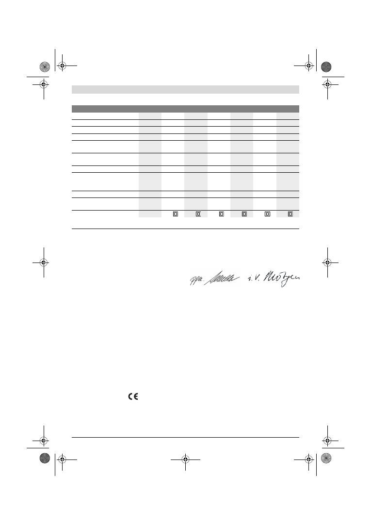
118
| Srpski
1 619 929 J37 | (2.2.12)
Bosch Power Tools
Tehnički podaci
Informacije o šumovima/vibracijama
Izmerene vrednosti buke utvrđene su u skladu sa EN 60745.
Nivo pritiska zvuka uredjaja vrednovan sa A tipično iznosi
76 dB(A). Nesigurnost K=3 dB.
Nivo buke pri radu može prekoračiti 80 dB(A).
Nosite zaštitu za sluh!
Ukupne vrednosti vibracija a
h
(zbir vektora tri pravca) i nesi-
gurnost K su dobujeni prema EN 60745:
a
h
=4,5 m/s
2
, K=1,5 m/s
2
.
Nivo vibracija naveden u ovim uputstvima je izmeren prema
mernom postupku koji je standardizovan u EN 60745 i može
da se koristi za poredjenje električnih alata jedan sa drugim.
Pogodan je i za privremenu procenu opterećenja vibracijama.
Navedeni nivo vibracija predstavlja prvenstveno primenu
električnog alata. Ako se svakako električni alat upotrebljava
za druge namene sa drugim upotrebljenim alatima ili
nedovoljno održavanja, može doći do odstupanja nivoa
vibracija. Ovo može u značajnoj meri povećati opterećenje
vibracijama preko celog radnog vremena.
Za tačnu procenu opterećenja vibracijama trebalo bi uzeti u
obzir i vreme, u kojem je uredjaj uključen ili radi, medjutim
nije stvarno u upotrebi. Ovo može značajno redukovati
opterećenje vibracijama preko celog radnog vremena.
Utvrdite dodatne mere sigurnosti radi zaštite radnika pre
delovanja vibracija kao na primer: Održavanje električnog
alata i upotrebljeni alati, održavanje toplih ruku, organizacija
odvijanja posla.
Izjava o usaglašenosti
Izjavljujemo na vlastitu odgovornost da je pod
„
Tehnički
podaci
“
opisani proizvod usaglašen sa sledećim standardima
ili normativnim aktima: EN 60745 prema odredbama
smernica 2011/65/EU, 2004/108/EG, 2006/42/EG.
Tehnička dokumentacija (2006/42/EG) kod:
Robert Bosch GmbH, PT/ETM9,
D-70745 Leinfelden-Echterdingen
Robert Bosch GmbH, Power Tools Division
D-70745 Leinfelden-Echterdingen
12.01.2012
Montaža
f
Izvucite pre svih radova na električnom alatu mrežni
utikač iz utičnice.
Usisavanje prašine/piljevine
f
Prašine od materijala kao što je premaz koji sadrži olovo,
neke vrste drveta, minerali i metal mogu biti štetni po
zdravlje. Dodir ili udisanje prašine mogu izazvati alergijske
reakcije i/ili oboljenja disajnih puteva radnika ili osoba koje
se nalaze u blizini.
Neke prašine kao od hrasta i bukve važe kao izazivači raka,
posebno u vezi sa dodatnim materijama za obradu drveta
(hromati, zaštitna sredstva za drvo). Materijal koji sadrži
azbest smeju raditi samo stručnjaci.
–
Koristite što je više moguće usisavanje prašine
pogodno za materijal.
–
Pobrinite se za dobro provetravanje radnog mesta.
–
Preporučuje se, da se nosi zaštitna maska za disanje sa
klasom filtera P2.
Vibraciona brusilica
GSS ...
230 A
230 AE
230 AE
280 A
280 AE
280 AE
Broj predmeta
0 601 ...
292 0..
292 7..
292 6..
293 0..
293 7..
293 6..
Kutija za prašinu u obimu isporuke
–
–
z
–
–
z
Biranje broja vibracija
–
z
z
–
z
z
Nominalna primljena snaga
W
300
300
300
330
330
330
Broj obrtaja na prazno
min
-1
11000
5500
–
11000
5500
–
11000
11000
5500
–
11000
5500
–
11000
Broj vibracija u praznom hodu
min
-1
22000
11000
–
22000
11000
–
22000
22000
11000
–
22000
11000
–
22000
Presek vibracionog kola
mm
2,4
2,4
2,4
2,4
2,4
2,4
Dimenzije brusnog lista
–
Čičak pričvršćivanje
–
Napon pritezanja
mm
mm
93 x 185
93 x 230
93 x 185
93 x 230
93 x 185
93 x 230
115 x 230
115 x 280
115 x 230
115 x 280
115 x 230
115 x 280
Dimenzije brusne ploče
mm
92 x 182
92 x 182
92 x 182 114 x 226 114 x 226 114 x 226
Težina prema EPTA-Procedure
01/2003
kg
2,3
2,3
2,3
2,6
2,6
2,6
Klasa zaštite
/
II
/
II
/
II
/
II
/
II
/
II
Podaci važe za nominalne napone [U] od 230 V. Kod napona koji odstupaju i izvodjenja specifičnih za zemlje mogu ovi podaci varirati.
Molimo da obratite pažnju na broj predmeta na tipskoj tablici Vašeg električnog alata. Trgovačke oznake pojedinih električnih alata mogu varirati.
Dr. Egbert Schneider
Senior Vice President
Engineering
Dr. Eckerhard Strötgen
Engineering Director
PT/ESI
OBJ_BUCH-426-005.book Page 118 Thursday, February 2, 2012 10:06 AM

Srpski |
119
Bosch Power Tools
1 619 929 J37 | (2.2.12)
Obratite pažnju na propise za materijale koje treba
obradjivati u Vašoj zemlji.
f
Izbegavajte sakupljanje prašine na radnom mestu.
Prašine se mogu lako zapaliti.
Sopstveno usisavanje sa kutijom zaprašinu
(pogledajte sliku A1
–
A4)
Pre montaže
6
kutije za prašinu izvucite plastični jezičak
13
.
Postavite kutiju za prašinu
6
na izduvni priključak
14
tako da
dosedne. Pazite da plastični jezičak
13
zahvata u držač
12
.
Za pražnjenje kese za prašinu
6
pritisnite polugu za blokadu
15
na strani kese za prašinu (
n
). Izvucite kesu za prašinu na
dole (
o
).
Pre otvaranja kutije za prašinu
6
trebali bi sa kutijom kao što
pokazuje slika da udarate na čvrstu podlogu, da bi odvojili
prašinu od filterskog elementa.
Kutiju za za prašinu
6
za udubljenje za hvatanje, podignite
filterski element
16
na gore i izvadite napolje i ispraznite kesu
za prašinu. Očistite lamele filterskog elementa
16
sa mekom
četkicom.
Usisavanje sa strane (pogledajte sliku B)
Nataknite adapter za usisavanje
17
na usisni priključak
14
.
Pazite na to, da poluga za blokadu adaptera za usisavanje
uskoči na svoje mesto. Na adapter za usisavanje
17
može da
se priključi neko crevo za usisavanje sa presekom od 19 mm.
Za demontažu adaptera za usisavanje
17
pritisnite njegovu
polugu za blokadu pozadi i izvucite adapter za usisavanje.
Usisivač mora biti pogodan za materijal koji treba obradjivati.
Upotrebljavajte prilikom usisavanja posebno po zdravlje
štetnih prašina, prašine koje izazivaju rak ili suvih prašina
specijalan usisivač.
Promena brusnog lista
Uklonite pre nameštanja novog lista za brušenje prljavštinu i
prašinu sa brusne ploče
9
, naprimer sa nekom četkicom.
Pazite radi obezbedjivanja optimalnog usisavanja prašine na
to, da izrezi na brusnom listu budu usaglašeni sa otvorima na
brusnoj ploči.
Brusni listovi sa čičak pričvršćivanjem
(pogledajte sliku C)
Brusna ploča
9
je opremljena sa čičak tkaninom, da bi brusni
listovi sa čičak pričvršćivanjem mogli brzo i jednostavno da se
pričvrste.
Istresite čičak tkaninu brusne ploče
9
pre nameštanja
brusnog lista
19
, da bi omogućili optimalno prijanjanje.
Postavite brusni list
19
na jednoj strani u ravni sa brusnom
pločom
9
, i na kraju stavite brusni list na brusnu ploču i dobro
ga pritisnite.
Za skidanje brusnog lista
19
uhvatite ga za vrh i svucite sa
brusne ploče
9
.
Brusni listovi bez čičak pričvršćivanja
(pogledajte sliku D)
Lako podignite priteznu sponu
8
i neka visi.
Vodite brusni list
19
do graničnika ispod otvorene zadnje
priključne letvice
10
i čvrsto stegnite brusni list vešanjem
spone
8
.
Stavite brusni list
19
zategnuto oko brusne ploče. Ubacite
drugi kraj brusnog lista
19
ispod otvorene prednje priključne
letvice
10
i čvrsto stegnite brusni list okačivši sponu
8
.
Neizbušeni brusni listovi, naprimer namotane odnosno
metarske robe, mogu da se za usisavanje prašine izbuše sa
alatom za bušenje otvora
20
. Pritisnite za ovo električni
pribor sa montiranim brusnim listom na perforirani pribor
(pogledajte sliku E).
Za skidanje brusnog lista
19
odvrnite pritezne spone
8
i
svucite brusni list.
Biranje brusnog lista
Prema materijalu koji se obradjuje i željenom skidanju
površine stoje na raspolaganju različiti brusni listovi:
Promena brusne ploče (pogledajte sliku F)
Brusna ploča
9
se može menjati po potrebi.
Izvadite potpuno napolje 6 zavrtanja
21
i skinite brusnu ploču
9
. Stavite novu brusnu ploču
9
i ponovo čvrsto stegnite
zavrtnje.
Specijalne brusne ploče
Možete isporučenu brusnu ploču
9
zameniti sa jednom
specijalnom brusnom pločom koja se dobija kao pribor.
Montaža specijalne brusne ploče vrši se shodno promeni
brusne ploče koja je isporučena.
Nameštanje i skidanje brusnog lista vrši se shodno promeni
originalnog brusnog lista.
Veličina zrna
40
–
400
Za obradu svih drvenih
materijala
Za prethodno brušenje, na primer
hrapavih, neobradjenih greda i
dasaka
grubo
40, 60
Za brušenje u ravni i ravnanje
malih neravnina
srednje 80, 100, 120
Za završno i fino brušenje tvrdog
drveta
fino
180, 240,
320, 400
40
–
320
Za obradu slojeva boje, laka
odnosno grundiranje kao što su
punioca i špahtel mase
Za brušenje boje
grubo
40, 60
Za brušenje prethodno
premazane boje
srednje 80, 100, 120
Za krajnje brušenje grundiranja
pre lakiranja
fino
180, 240, 320
OBJ_BUCH-426-005.book Page 119 Thursday, February 2, 2012 10:06 AM

120
| Srpski
1 619 929 J37 | (2.2.12)
Bosch Power Tools
Pravougla, tanka, produžena brusna ploča
(GSS 230 A/GSS 230 AE) (pogledajte sliku G)
Primena pravougle, tanke, produžene brusne ploče
22
omogućava Vam brušenje na teško dostupnim mestima i
uskim međuprostorima, kao što su na primer lamele prozora i
vrata, utori ili površine iza grejnih ili vodovodnih cevi.
Za montažu pravougle, tanke, produžene brusne ploče
22
koristite pripadajuće zavrtnje
24
.
Trouglasta produžena brusna ploča
(GSS 230 A/GSS 230 AE) (pogledajte sliku H)
Primena trouglaste produžene brusne ploče
26
omogućava
Vam brušenje u uglovima i po ivicama.
Ploča za fino brušenje (bez čičak pričvršćivanja)
(GSS 230 AE/GSS 280 AE) (pogledajte sliku D)
Pri pretežnoj upotrebi standardnih brusnih listova bez čičak
pričvršćivanja preporučuje se primena ploče za fino brušenje
bez čičak pričvršćivanja. Zahvaljujući ravnoj brusnoj površini
ove brusne ploče postižu se optimalni rezultati naročito kod
finog brušenja.
Dodatna drška
Dodatna drška
1
omogućava komotno rukovanje i optimalnu
raspodelu sile pre svega u slučajevima obimnog skidanja
materijala pri brušenju.
Pričvrstite dodatnu dršku
1
zavrtnjem
2
na kućište.
Rad
Puštanje u rad
f
Obratite pažnju na napon mreže! Napon strujnog izvora
mora biti usaglašen sa podacima tipske tablice
električnog alata. Električni alati označeni sa 230 V
mogu da rade i sa 220 V.
Uključivanje-isključivanje
Pritisnite za
puštanje u rad
električnog alata prekidač za
uključivanje-isključivanje
4
i držite ga pritisnut.
Za
fiksiranje
pritisnutog prekidača za uključivanje-
isključivanje
4
pritisnite taster za fiksiranje
5
.
Da bi električni alat
isključili
pustite prekidač za
uključivanje-isključivanje
4
odnosno ako je blokiran sa
tasterom za fiksiranje
5
, pritisnite prekidač za uključivanje-
isključivanje
4
na kratko i potom ga pustite.
Biranje broja vibracija (GSS 230 AE/GSS 280 AE)
Za točkićem za podešavanje broja vibracija
3
možete unapred
izabrati potreban broj vibracija i za vreme rada.
Potreban broj vibracija zavisi od materijala i radnih uslova i
može se dobiti praktičnom probom.
Uputstva za rad
f
Sačekajte da se električni alat umiri, pre nego što ga
ostavite.
Učinak skidanja prilikom brušenja se u bitnom odredjuje
biranjem brusnog lista kao i izabranim brojem vibracija
(GSS 230 AE/GSS 280 AE).
Samo besprekorni brusni listovi daju dobar učinak brušenja i
čuvaju električni alat.
Pazite na ravnomeran pritisak, da bi povećali životni vek
brusnih listova.
Prekomerno povećavanje pritiska ne vodi većem učinku
brušenja, već jačem habanju električnog alata i brusnog lista.
Ne koristite više brusni list sa kojim je obradjivan metal, za
druge materijale.
Upotrebljavajte samo originalni Bosch brusni pribor.
Održavanje i servis
Održavanje i čišćenje
f
Izvucite pre svih radova na električnom alatu mrežni
utikač iz utičnice.
f
Držite električni alat i proreze za ventilaciju čiste, da bi
dobro i sigurno radili.
Ako je potrebna zamena za priključni vod, onda to mora
izvesti Bosch ili stručan servis za Bosch-električne alata da bi
se izbegle opasnosti po sigurnost.
Ako bi električni alat i pored brižljivog postupka izrade i
kontrole nekada otkazao, popravku mora vršiti neki stručan
servis za Bosch-električne alate.
Molimo navedite neizostavno kod svih pitanja i naručivanja
rezervnih delova broj predmeta sa 10 brojčanih mesta prema
tipskoj tablici električnog alata.
Servis i savetovanja kupaca
Servis odgovara na Vaša pitanja u vezi popravke i održavanja
Vašeg proizvoda kao i u vezi rezervnih delova. Šematske
prikaze i informacije u vezi rezervnih delova naći ćete i pod:
www.bosch-pt.com
Bosch-ov tim savetnika će Vam pomoći kod pitanja u vezi
kupovine, primene i podešavanja proizvoda i pribora.
Srpski
Bosch-Service
Dimitrija Tucovića 59
11000 Beograd
Tel.: +381 (011) 244 85 46
Fax: +381 (011) 241 62 93
E-Mail: asboschz@EUnet.yu
Uklanjanje djubreta
Električni pribori, pribor i pakovanja treba da se odvoze
regeneraciji koja odgovara zaštiti čovekove sredine.
Ne bacajte električni alat u kućno djubre!
Samo za EU-zemlje:
Prema evropskim smernicama
2002/96/EG o starim električnim i
elektronskim uredjajima i njihovim
pretvaranju u nacionalno dobro ne moraju
više neupotrebljivi električni pribori da se
odvojeno sakupljaju i odvoze nekoj reciklaži
koja odgovara zaštiti čovekove okoline.
Zadržavamo pravo na promene.
OBJ_BUCH-426-005.book Page 120 Thursday, February 2, 2012 10:06 AM
Slovensko |
121
Bosch Power Tools
1 619 929 J37 | (2.2.12)
Slovensko
Varnostna navodila
Splošna varnostna navodila za električna orodja
Preberite vsa opozorila in napotila.
Napake zaradi neupoštevanja spodaj
navedenih opozoril in napotil lahko povzročijo električni udar,
požar in/ali težke telesne poškodbe.
Vsa opozorila in napotila shranite, ker jih boste v
prihodnje še potrebovali.
Pojem
„
električno orodje
“
, ki se pojavlja v nadaljnjem
besedilu, se nanaša na električna orodja z električnim
pogonom (z električnim kablom) in na akumulatorska
električna orodja (brez električnega kabla).
Varnost na delovnem mestu
f
Delovno področje naj bo vedno čisto in dobro
osvetljeno.
Nered in neosvetljena delovna področja lahko
povzročijo nezgode.
f
Ne uporabljajte električnega orodja v okolju, kjer lahko
pride do eksplozij oziroma tam, kjer se nahajajo
vnetljive tekočine, plini ali prah.
Električna orodja
povzročajo iskrenje, zaradi katerega se lahko prah ali para
vnameta.
f
Prosimo, da med uporabo električnega orodja ne
dovolite otrokom ali drugim osebam, da bi se Vam
približali.
Odvračanje Vaše pozornosti drugam lahko
povzroči izgubo kontrole nad napravo.
Električna varnost
f
Priključni vtikač električnega orodja se mora prilegati
vtičnici. Spreminjanje vtikača na kakršenkoli način ni
dovoljeno. Pri ozemljenih električnih orodjih ne upo-
rabljajte vtikačev z adapterji.
Nespremenjeni vtikači in
ustrezne vtičnice zmanjšujejo tveganje električnega udara.
f
Izogibajte se telesnemu stiku z ozemljenimi površinami
kot so na primer cevi, grelci, štedilniki in hladilniki.
Tveganje električnega udara je večje, če je Vaše telo
ozemljeno.
f
Prosimo, da napravo zavarujete pred dežjem ali vlago.
Vdor vode v električno orodje povečuje tveganje
električnega udara.
f
Ne uporabljajte kabla za nošenje ali obešanje
električnega orodja in ne vlecite za kabel, če želite
vtikač izvleči iz vtičnice. Kabel zavarujte pred vročino,
oljem, ostrimi robovi ali premikajočimi se deli naprave.
Poškodovani ali zapleteni kabli povečujejo tveganje
električnega udara.
f
Kadar uporabljate električno orodje zunaj, uporabljajte
samo kabelske podaljške, ki so primerni za delo na pro-
stem.
Uporaba kabelskega podaljška, ki je primeren za
delo na prostem, zmanjšuje tveganje električnega udara.
f
Če je uporaba električnega orodja v vlažnem okolju
neizogibna, uporabljajte stikalo za zaščito pred
kvarnim tokom.
Uporaba zaščitnega stikala zmanjšuje
tveganje električnega udara.
Osebna varnost
f
Bodite pozorni, pazite kaj delate ter se dela z
električnim orodjem lotite z razumom. Ne uporabljajte
električnega orodja, če ste utrujeni oziroma če ste pod
vplivom mamil, alkohola ali zdravil.
Trenutek
nepazljivosti med uporabo električnega orodja je lahko
vzrok za resne telesne poškodbe.
f
Uporabljajte osebno zaščitno opremo in vedno nosite
zaščitna očala.
Nošenje osebne zaščitne opreme, na
primer maske proti prahu, nedrsečih zaščitnih čevljev,
varnostne čelade ali zaščitnih glušnikov, kar je odvisno od
vrste in načina uporabe električnega orodja, zmanjšuje
tveganje telesnih poškodb.
f
Izogibajte se nenamernemu zagonu. Pred priključitvijo
električnega orodja na električno omrežje in/ali na
akumulator in pred dviganjem ali nošenjem se prepri-
čajte, če je električno orodje izklopljeno.
Prenašanje
naprave s prstom na stikalu ali priključitev vklopljenega
električnega orodja na električno omrežje je lahko vzrok za
nezgodo.
f
Pred vklapljanjem električnega orodja odstranite
nastavitvena orodja ali izvijače.
Orodje ali ključ, ki se
nahaja v vrtečem se delu naprave, lahko povzroči telesne
poškodbe.
f
Izogibajte se nenormalni telesni drži. Poskrbite za
trdno stojišče in za stalno ravnotežje.
Tako boste v
nepričakovanih situacijah električno orodje lahko bolje
nadzorovali.
f
Nosite primerna oblačila. Ne nosite ohlapnih oblačil in
nakita. Lase, oblačila in rokavice ne približujte
premikajočim se delom naprave.
Premikajoči se deli
naprave lahko zagrabijo ohlapno oblačilo, dolge lase ali
nakit.
f
Če je na napravo možno montirati priprave za
odsesavanje ali prestrezanje prahu, se prepričajte, če
so le-te priključene in če se pravilno uporabljajo.
Uporaba priprave za odsesavanje prahu zmanjšuje
zdravstveno ogroženost zaradi prahu.
Skrbna uporaba in ravnanje z električnimi orodji
f
Ne preobremenjujte naprave. Pri delu uporabljajte
električna orodja, ki so za to delo namenjena.
Z
ustreznim električnim orodjem boste v navedenem
zmogljivostnem področju delali bolje in varneje.
f
Ne uporabljajte električnega orodja s pokvarjenim
stikalom.
Električno orodje, ki se ne da več vklopiti ali
izklopiti, je nevarno in ga je potrebno popraviti.
f
Pred nastavljanjem naprave, zamenjavo delov pribora
ali odlaganjem naprave izvlecite vtikač iz električne
vtičnice in/ali odstranite akumulator.
Ta previdnostni
ukrep preprečuje nenameren zagon električnega orodja.
OPOZORILO
OBJ_BUCH-426-005.book Page 121 Thursday, February 2, 2012 10:06 AM
122
| Slovensko
1 619 929 J37 | (2.2.12)
Bosch Power Tools
f
Električna orodja, katerih ne uporabljate, shranjujte
izven dosega otrok. Osebam, ki naprave ne poznajo ali
niso prebrale teh navodil za uporabo, naprave ne
dovolite uporabljati.
Električna orodja so nevarna, če jih
uporabljajo neizkušene osebe.
f
Skrbno negujte električno orodje. Kontrolirajte
brezhibno delovanje premičnih delov naprave, ki se ne
smejo zatikati. Če so ti deli zlomljeni ali poškodovani do
te mere, da ovirajo delovanje električnega orodja, jih je
potrebno pred uporabo naprave popraviti.
Slabo
vzdrževana električna orodja so vzrok za mnoge nezgode.
f
Rezalna orodja vzdržujte tako, da bodo vedno ostra in
čista.
Skrbno negovana rezalna orodja z ostrimi robovi se
manj zatikajo in so lažje vodljiva.
f
Električna orodja, pribor, vsadna orodja in podobno
uporabljajte ustrezno tem navodilom. Pri tem
upoštevajte delovne pogoje in dejavnost, ki jo boste
opravljali.
Uporaba električnih orodij v namene, ki so
drugačni od predpisanih, lahko privede do nevarnih
situacij.
Servisiranje
f
Vaše električno orodje naj popravlja samo kvalificirano
strokovno osebje ob obvezni uporabi originalnih
rezervnih delov.
Tako bo zagotovljena ohranitev varnosti
naprave.
Varnostna navodila za brusilnike
f
Električno orodje uporabljajte samo za suho brušenje.
Vdor vode v električno napravo povečuje tveganje
električnega udara.
f
Pozor, nevarnost požara! Izogibajte se pregrevanju
obdelovanca in brusilnika. Pred delovnimi odmori
vedno izpraznite zbiralnik prahu.
Brusilni prah v vrečki
za prah, mikrofiltru, papirni vrečki (ali v filtrski vrečki
oziroma filtru sesalnika za prah) se lahko v neugodnih
pogojih, na primer pri iskrenju med brušenjem kovin,
samodejno vname. Posebno nevarno je takrat, ko je
brusilni prah pomešan z ostanki laka, poliuretana ali drugih
kemičnih snovi, brusilnik pa je po dolgem delovanju vroč.
f
Medtem ko delate, trdno držite električno orodje z
obema rokama in poskrbite za varno stojišče.
Električno
orodje bo bolj vodljivo, če ga boste držali z obema rokama.
f
Zavarujte obdelovanec.
Obdelovanec bo proti
premikanju bolje zavarovan z vpenjalnimi pripravami ali s
primežem, kot če bi ga držali z roko.
Opis in zmogljivost izdelka
Preberite vsa opozorila in napotila.
Napake
zaradi neupoštevanja spodaj navedenih
opozoril in napotil lahko povzročijo električni
udar, požar in/ali težke telesne poškodbe.
Razprite stran s sliko naprave in pustite to stran med branjem
navodil za uporabo odprto.
Uporaba v skladu z namenom
Naprava je namenjena za suho brušenje lesa, umetne snovi,
kita za lopatico in lakiranih površin.
Komponente na sliki
Oštevilčenje komponent, ki so prikazane na sliki, se nanaša na
prikaz električnega orodja na strani z grafiko.
1
Dodatni ročaj (izolirana površina ročaja)*
2
Vijak za dodatni ročaj*
3
Gumb za nastavitev števila nihajev
(GSS 230 AE/GSS 280 AE)
4
Vklopno/izklopno stikalo
5
Tipka za fiksiranje vklopno/izklopnega stikala
6
Komplet zbiralnika za prah (Microfilter System)*
7
Inbus ključ
8
Držalni lok
9
Brusilna plošča
10
Držalna letev
11
Ročaj (izolirana površina ročaja)
12
Držalo zbiralnika za prah*
13
Plastično pomikalo
14
Izpihovalni nastavek
15
Ročica za aretiranje zbiralnika za prah*
16
Filtrirni element (Microfilter System)*
17
Odsesovalni adapter*
18
Odsesovalna cev*
19
Brusilni list*
20
Luknjalnik*
21
Vijaki za brusilno ploščo
22
Brusilna plošča, tanka, podaljšana*
23
Brusilni list, podaljšan*
24
Vijaki za podaljšano brusilno ploščo*
25
Brusilni list, trikotne oblike*
26
Brusilna plošča, trikotne oblike, podaljšana*
*Prikazan ali opisan pribor ni del standarnega obsega dobave.
Celoten pribor je del našega programa pribora.
Tehnični podatki
Vibracijski brusilnik
GSS ...
230 A
230 AE
230 AE
280 A
280 AE
280 AE
Številka artikla
0 601 ...
292 0..
292 7..
292 6..
293 0..
293 7..
293 6..
Zbiralnik za prah v dobavnem
obsegu
–
–
z
–
–
z
Predizbira števila nihajev
–
z
z
–
z
z
Navedbe veljajo za nazivne napetosti [U] 230 V. Pri drugih napetostih in državno specifičnih izvedbah lahko te navedbe variirajo.
Prosimo, da upoštevate številko artikla na tipski ploščici Vašega električnega orodja. Trgovske oznake posameznih električnih orodij so lahko drugačne.
OBJ_BUCH-426-005.book Page 122 Thursday, February 2, 2012 10:06 AM
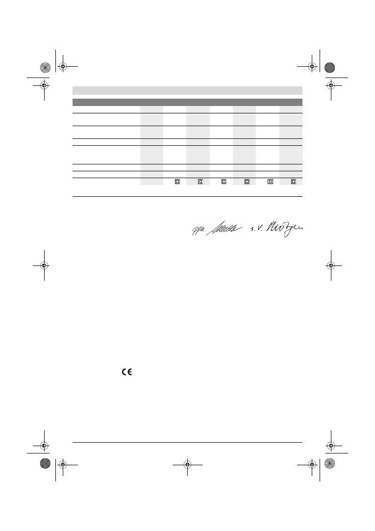
Slovensko |
123
Bosch Power Tools
1 619 929 J37 | (2.2.12)
Podatki o hrupu/vibracijah
Merilne vrednosti hrupa izračunane v skladu z EN 60745.
Nivo zvočnega tlaka naprave po vrednotenju A znaša tipično
76 dB(A). Netočnost K=3 dB.
Nivo hrupa lahko pri delu preseže 80 dB(A).
Uporabljajte zaščitne glušnike!
Skupne vrednosti vibracij a
h
(vektorska vsota treh smeri) in
negotovost K se izračunajo v skladu z EN 60745:
a
h
=4,5 m/s
2
, K=1,5 m/s
2
.
Podane vrednosti nivoja vibracij v teh navodilih so se izmerile
v skladu s standardiziranim merilnim postopkom po
EN 60745 in se lahko uporabljajo za primerjavo električnih
orodij med seboj. Primeren je tudi za začasno oceno
obremenjenosti z vibracijami.
Naveden nivo vibracij predstavlja glavne uporabe
električnega orodja. Če pa se električno orodje uporablja še v
druge namene, z odstopajočimi vstavnimi orodji ali pri
nezadostnem vzdrževanju, lahko nivo vibracij odstopa. To
lahko obremenjenosti z vibracijami med določenim obdobjem
uporabe občutno poveča.
Za natančnejšo oceno obremenjenosti z vibracijami morate
upoštevati tudi tisti čas, ko je naprava izklopljena in teče,
vendar dejansko ni v uporabi. To lahko ombremenjenost z
vibracijami preko celotnega obdobja dela občutno zmanjša.
Določite dodatne varnostne ukrepe za zaščito upravljalca
pred vpljivi vibracij, npr. Vzdrževanje električnega orodja in
vstavnih orodij, zegrevanje rok, organizacija delovnih
postopkov.
Izjava o skladnosti
Izjavljamo pod izključno odgovornostjo, da proizvod pod
„
Tehnični podatki
“
ustreza naslednjim standardom oz.
standardiziranim dokumentom: EN 60745 v skladu z določili
Direktiv 2011/65/EU, 2004/108/ES, 2006/42/ES.
Tehnična dokumentacija (2006/42/ES) pri:
Robert Bosch GmbH, PT/ETM9,
D-70745 Leinfelden-Echterdingen
Robert Bosch GmbH, Power Tools Division
D-70745 Leinfelden-Echterdingen
12.01.2012
Montaža
f
Pred začetkom kakršnih koli del na električnem orodju
izvlecite omrežni vtikač iz vtičnice.
Odsesavanje prahu/ostružkov
f
Prah nekaterih materialov kot npr. svinčenega premaza,
nekaterih vrst lesa, mineralov in kovin je lahko zdravju
škodljiv. Dotik ali vdihavanje tega prahu lahko povzroči
alergične reakcije in/ali obolenja dihal uporabnika ali oseb,
ki se nahajajo v bližini.
Določene vrste prahu kot npr. prah hrastovine ali bukovja
veljajo kot kancerogene, še posebej v povezavi z dodatnimi
snovmi za obdelavo lesa (kromat, zaščitno sredstvo za
les). Material z vsebnostjo azbesta smejo obdelovati le
strokovnjaki.
–
Po možnosti uporabljajte sesalnik prahu, ki je
primeren glede na vrsto materiala.
–
Poskrbite za dobro zračenje delovnega mesta.
–
Priporočamo, da nosite zaščitno masko za prah s
filtrirnim razredom P2.
Upoštevajte veljavne nacionalne predpise za obdelovalne
materiale.
f
Preprečite nabiranje prahu na delovnem mestu.
Prah se
lahko hitro vname.
Nazivna odjemna moč
W
300
300
300
330
330
330
Število vrtljajev v prostem teku
min
-1
11000
5500
–
11000
5500
–
11000
11000
5500
–
11000
5500
–
11000
Število nihanj v prostem teku
min
-1
22000
11000
–
22000
11000
–
22000
22000
11000
–
22000
11000
–
22000
Premer nihajnega kroga
mm
2,4
2,4
2,4
2,4
2,4
2,4
Dimenzije brusilnega lista
–
pritrditev s sprijemanjem
–
vpenjanje z zatiči
mm
mm
93 x 185
93 x 230
93 x 185
93 x 230
93 x 185
93 x 230
115 x 230
115 x 280
115 x 230
115 x 280
115 x 230
115 x 280
Dimenzije brusilne plošče
mm
92 x 182
92 x 182
92 x 182 114 x 226 114 x 226 114 x 226
Teža po EPTA-Procedure 01/2003
kg
2,3
2,3
2,3
2,6
2,6
2,6
Zaščitni razred
/
II
/
II
/
II
/
II
/
II
/
II
Vibracijski brusilnik
GSS ...
230 A
230 AE
230 AE
280 A
280 AE
280 AE
Navedbe veljajo za nazivne napetosti [U] 230 V. Pri drugih napetostih in državno specifičnih izvedbah lahko te navedbe variirajo.
Prosimo, da upoštevate številko artikla na tipski ploščici Vašega električnega orodja. Trgovske oznake posameznih električnih orodij so lahko drugačne.
Dr. Egbert Schneider
Senior Vice President
Engineering
Dr. Eckerhard Strötgen
Engineering Director
PT/ESI
OBJ_BUCH-426-005.book Page 123 Thursday, February 2, 2012 10:06 AM

124
| Slovensko
1 619 929 J37 | (2.2.12)
Bosch Power Tools
Lastno odsesavanje z zbiralnikom za prah
(glejte slike A1
–
A4)
Pred montažo zbiralnika za prah
6
potegnite ven plastično
pomikalo
13
. Nataknite zbiralnik za prah
6
na izpihovalni
nastavek
14
, dokler ne zaskoči. Pazite na to, da plastično
pomikalo
13
prime v držalo
12
.
Za praznjenje zbiralnika za prah
6
pritisnite aretirno ročico
15
ob strani zbiralnika (
n
). V smeri navzdol odstranite zbiralnik
za prah (
o
).
Pred odpiranjem zbiralnika za prah
6
potrkajte z njim ob
stabilno podlago, kot je prikazano na sliki. Tako se bo prah, ki
se je nabral v filtrirnem elementu, sprostil.
Zgrabite zbiralnik za prah
6
za prijemno vdolbino, v smeri
navzgor odstranite filtrirni element
16
in izpraznite zbiralnik
za prah. Lamele filtrirnega elementa
16
očistite z mehko
ščetko.
Odsesavanje s tujim sesalnikom (glejte sliko B)
Odsesovalni adapter
17
namestite na izpihovalni nastavek
14
. Pazite, da bosta aretirni ročici odsesovalnega adapterja
pravilno zaskočili. Na odsesovalni adapter
17
lahko priključite
odsesovalno cev s premerom 19 mm.
Za demontažo odsesovalnega adapterja
17
stisnite njegovo
zadnjo aretirno ročico skupaj in snemite adapter.
Odsesovalnik za prah mora ustrezati obdelovancu, ki ga boste
brusili.
Za odsesovanje izredno zdravju nevarnih, kancerogenih ali
suhih vrst prahu uporabljajte specialni sesalnik za prah.
Zamenjava brusilnega lista
Pred namestitvijo novega brusilnega lista odstranite z
brusilne plošče
9
umazanijo in prah, na primer s čopičem.
Zaradi zagotovitve optimalnega odsesavanja prahu pazite, da
se bodo odprtine v brusilnem listu ujemale z luknjami na
brusilni plošči.
Brusilni listi s sprijemalno pritrditvijo (glejte sliko C)
Brusilna plošča
9
je opremljena s sprijemalno tkanino, ki
omogoča hitro in enostavno pritrjevanje brusilnih listov.
Potrkajte po sprijemalni tkanini brusilne plošče
9
preden
namestite brusilni list
19
in tako zagotovite optimalno
oprijemanje.
Brusilni list
19
poravnajte z eno stranjo brusilne plošče
9
,
nato položite brusilni list na brusilno ploščo in ga dobro
pritisnite.
Brusilni list
19
odstranite tako, da primete na enem koncu in
ga potegnete z brusilne plošče
9
.
Brusilni listi brez sprijemalne pritrditve (glejte sliko D)
Rahlo privzdignite in držalni lok
8
in ga snemite.
Vodite brusilni list
19
do naslona pod odprto zadnjo držalno
letev
10
in napnite brusilni list z nataknitvijo držalnega loka
8
.
Namestite brusilni list
19
trdno okrog brusilne plošče. Vodite
drug konec brusilnega lista
19
pod odprto spredjo držalno
letev
10
in napnite brusilni list z nataknitvijo držalnega loka
8
.
Nepreluknjane brusilne liste, na primer liste ki so naviti na
rolah oziroma so na voljo kot metrsko blago, lahko preluknjate
z luknjalnikom
20
in tako omogočite odsesavanje prahu.
V ta namen električno orodje z montiranim brusilnim listom
pritisnite na luknjalnik (glejte sliko E).
Brusilni list
19
odstranite tako, da sprostite držalni lok
8
in
potegnete brusilni list ven.
Izbira brusilnega lista
Odvisno od materiala, ki se bo obdeloval in želene količine
odstranjevanja zgornje površine so na voljo različni brusilni
listi:
Zamenjava brusilne plošče (glejte sliko F)
Brusilno ploščo
9
lahko po potrebi zamenjate.
Do konca odvijte 6 vijakov
21
in odstranite brusilno ploščo
9
.
Namestite novo brusilno ploščo
9
in znova trdno privijte
vijake.
Posebne brusilne plošče
Dobavljeno brusilno ploščo
9
lahko zamenjate s posebno
brusilno ploščo, ki jo naročite kot dodatni pribor.
Montažo posebne brusilne plošče lahko opravite na način,
ki je predviden za zamenjavo dobavljene brusilne plošče.
Namestitev in odstranitev brusilnega lista je enaka zamenjavi
originalnega brusilnega lista.
Podaljšana brusilna plošča, pravokotna, tanka
(GSS 230 A/GSS 230 AE) (glejte sliko G)
Uporaba pravokotne, tanke, podaljšane brusilne plošče
22
omogoči brušenje na težko dostopnih mestih in ozkih
vmesnih prostorih, npr. pri oknih in lamelih vrat, utorih ali za
radiatorji in vodovodnimi cevmi.
Za montažo pravokotne, tanke, podaljšane, brusilne plošče
22
uporabite pripadajoče vijake
24
.
Granulacija
40
–
400
Za obdelovanje vseh lesenih
površin
Za predbrušenje, na primer
grobih, nepooblanih tramov in
desk
groba
40, 60
Za plano brušenje in
poravnavanje manjših neravnih
površin
srednja 80, 100, 120
Za končno in fino brušenje trdega
lesa
fino
180, 240,
320, 400
40
–
320
Za brušenje slojev barve in laka
oziroma temeljnih slojev,
kakršna sta na primer polnilna
masa in kit za lopatico
Za brušenje barve
groba
40, 60
Za brušenje temeljne barve
srednja 80, 100, 120
Za končno brušenje temeljne
barve pred lakiranjem
fino
180, 240, 320
OBJ_BUCH-426-005.book Page 124 Thursday, February 2, 2012 10:06 AM
Slovensko |
125
Bosch Power Tools
1 619 929 J37 | (2.2.12)
Podaljšan brusilni list, trikotne oblike
(GSS 230 A/GSS 230 AE) (glejte sliko H)
Uporaba trikotno podaljšane brusilne plošče
26
vam omogoči
brušenje v kotih in robovih.
Fina brusilna plošča (brez sprijemala)
(GSS 230 AE/GSS 280 AE) (glejte sliko D)
Pri prevladujoči uporabi standarnih brusilnih listov brez
sprijemala priporočamo uporabo fine brusilne plošče brez
sprijemala. Zaradi gladke površine brusilne plošče se posebej
pri finem brušenju dosežejo optimalni brusilni rezultati.
Dodatni ročaj
Dodatni ročaj
1
omogoči udobno rokovanje in optimalno
porazdelitev moči, še posebej pri velikih globinah brušenja.
Pritrdite dodatni ročaj
1
z vijakom
2
na ohišju.
Delovanje
Zagon
f
Upoštevajte omrežno napetost! Napetost vira
električne energije se mora ujemati s podatki na tipski
ploščici električnega orodja. Orodje, ki je označeno z
230 V, lahko priključite tudi na napetost 220 V.
Vklop/izklop
Za
zagon
električnega orodja pritisnite vklopno/izklopno
stikalo
4
in ga držite pritisnjenega.
Za
fiksiranje
pritisnjenega vklopno/izklopnega stikala
4
pritisnite tipko za fiksiranje
5
.
Če želite električno orodje
izklopiti
, vklopno/izklopno stikalo
4
spustite, če pa je stikalo aretirano s tipko za fiksiranje
5
,
vklopno/izklopno stikalo
4
najprej kratko pritisnite in ga nato
spustite.
Predizbira števila nihajev (GSS 230 AE/GSS 280 AE)
Z gumbom za prednastavitev števila nihajev
3
lahko potrebno
število nihajev nastavite tudi med delovanjem naprave.
Ustrezno število nihajev je odvisno od materiala in od
delovnih pogojev, ugotovite pa ga lahko s praktičnim
poizkusom.
Navodila za delo
f
Pred odlaganjem električnega orodja počakajte, da se
le to popolnoma ustavi.
Količina odstranjenega materala pri brušenju je odvisna
predvsem od izbire brusilnega lista in od prednastavljenega
števila nihanj (GSS 230 AE/GSS 280 AE).
Dober rezultat brušenja zagotavljajo samo brezhibni brusilni
listi, ki tudi varujejo električno orodje.
Na obdelovanec vedno pritiskajte z enakomerno močjo, kar
bo podaljšalo življenjsko dobo brusilnega ista.
Prekomerno povečanje moči pritiskanja ne bo zagotovilo
večje brusilne zmogljivosti, temveč bo povzročilo močnejšo
obrabo električnega orodja in brusilnega lista.
Brusilnega lista, s katerim ste obdelovali kovino, ne smete
uporabljati za brušenje drugih materialov.
Uporabljajte samo originalni brusilni pribor Bosch.
Vzdrževanje in servisiranje
Vzdrževanje in čiščenje
f
Pred začetkom kakršnih koli del na električnem orodju
izvlecite omrežni vtikač iz vtičnice.
f
Električno orodje in prezračevalne reže naj bodo vedno
čisti, kar bo zagotovilo dobro in varno delo.
Da bi se izognili ogrožanju varnosti v primeru, da morate
nadomestiti priključni kabel, mora to storiti servis podjetja
Bosch ali pooblaščen servis za električna orodja Bosch.
Če bi kljub skrbnima postopkoma izdelave in preizkušanja
prišlo do izpada delovanja električnega orodja, naj popravilo
opravi servisna delavnica, pooblaščena za popravila
Boschevih električnih orodij.
V primeru dodatnih vprašanj in pri naročanju nadomestnih
delov brezpogojno navedite 10-mestno številko artikla, ki je
navedena na tipski ploščici naprave.
Servis in svetovanje
Servis vam bo dal odgovore na vaša vprašanja glede popravila
in vzdrževanja izdelka ter nadomestnih delov. Prikaze
razstavljenega stanja in informacije glede nadomestnih delov
se nahajajo tudi na internetnem naslovu:
www.bosch-pt.com
Skupina svetovalcev podjetja Bosch vam bo z veseljem na
voljo pri vprašanjih glede nakupa, uporabe in nastavitve
izdelka in pribora.
Slovensko
Top Service d.o.o.
Celovška 172
1000 Ljubljana
Tel.: +386 (01) 5194 225
Tel.: +386 (01) 5194 205
Fax: +386 (01) 5193 407
Odlaganje
Električno orodje, pribor in embalažo je treba dostaviti v
okolju prijazno ponovno predelavo.
Električnih orodij ne vrzite med gospodinjske odpadke!
Samo za države EU:
V skladu z Direktivo 2002/96/ES
Evropskega Parlamenta in Sveta o odpadni
električni in elektronski opremi (OEEO) in
njeni uresničitvi v nacionalnem pravu se
morajo električna orodja, ki niso več v
uporabi, ločeno zbirati ter okolju prijazno
reciklirati.
Pridržujemo si pravico do sprememb.
OBJ_BUCH-426-005.book Page 125 Thursday, February 2, 2012 10:06 AM

126
| Hrvatski
1 619 929 J37 | (2.2.12)
Bosch Power Tools
Hrvatski
Upute za sigurnost
Opće upute za sigurnost za električne alate
Treba pročitati sve napomene o
sigurnosti i upute.
Ako se ne bi
poštivale napomene o sigurnosti i upute to bi moglo
uzrokovati strujni udar, požar i/ili teške ozljede.
Sačuvajte sve napomene o sigurnosti i upute za buduću
primjenu.
U daljnjem tekstu korišten pojam
„
Električni alat
“
odnosi se na
električne alate s priključkom na električnu mrežu (s mrežnim
kabelom) i na električne alate s napajanjem iz aku baterije
(bez mrežnog kabela).
Sigurnost na radnom mjestu
f
Održavajte vaše radno mjesto čistim i dobro
osvijetljenim.
Nered ili neosvijetljeno radno mjesto mogu
uzrokovati nezgode.
f
Ne radite s električnim alatom u okolini ugroženoj
eksplozijom, u kojoj se nalaze zapaljive tekućine,
plinovi ili prašina.
Električni alati proizvode iskre koje
mogu zapaliti prašinu ili pare.
f
Tijekom uporabe električnog alata djecu i ostale osobe
držite dalje od mjesta rada.
U slučaju skretanja
pozornosti mogli bi izgubiti kontrolu nad uređajem.
Električna sigurnost
f
Priključni utikač električnog alata mora odgovarati
utičnici. Na utikaču se ni na koji način ne smiju izvoditi
izmjene. Ne koristite adapterski utikač zajedno sa
zaštitno uzemljenim električnim alatom.
Utikač na
kojem nisu vršene izmjene i odgovarajuća utičnica
smanjuju opasnost od strujnog udara.
f
Izbjegavajte dodir tijela s uzemljenim površinama, kao
što su cijevi, radijatori, štednjaci i hladnjaci.
Postoji
povećana opasnost od električnog udara ako bi vaše tijelo
bilo uzemljeno.
f
Uređaj držite dalje od kiše ili vlage.
Prodiranje vode u
električni alat povećava opasnost od strujnog udara.
f
Ne zloupotrebljavajte priključni kabel za nošenje,
vješanje električnog alata ili za izvlačenje utikača iz
mrežne utičnice. Priključni kabel držite dalje od izvora
topline, ulja, oštrih rubova ili pomičnih dijelova
uređaja.
Oštećen ili usukan priključni kabel povećava
opasnost od strujnog udara.
f
Ako sa električnim alatom radite na otvorenom,
koristite samo produžni kabel koji je prikladan za
uporabu na otvorenom.
Primjena produžnog kabela
prikladnog za rad na otvorenom smanjuje opasnost od
strujnog udara.
f
Ako se ne može izbjeći uporaba električnog alata u
vlažnoj okolini, koristite zaštitnu sklopku struje kvara.
Primjenom zaštitne sklopke struje kvara izbjegava se
opasnost od električnog udara.
Sigurnost ljudi
f
Budite pažljivi, pazite što činite i postupajte oprezno
kod rada s električnim alatom. Ne koristite električni
alat ako ste umorni ili pod utjecajem droga, alkohola ili
lijekova.
Trenutak nepažnje kod uporabe električnog alata
može uzrokovati teške ozljede.
f
Nosite osobnu zaštitnu opremu i uvijek nosite zaštitne
naočale.
Nošenje osobne zaštitne opreme, kao što je
maska za prašinu, sigurnosna obuća koja ne kliže, zaštitna
kaciga ili štitnik za sluh, ovisno od vrste i primjene
električnog alata, smanjuje opasnost od ozljeda.
f
Izbjegavajte nehotično puštanje u rad. Prije nego što
ćete utaknuti utikač u utičnicu i/ili staviti aku-bateriju,
provjerite je li električni alat isključen.
Ako kod nošenja
električnog alata imate prst na prekidaču ili se uključen
uređaj priključi na električno napajanje, to može dovesti do
nezgoda.
f
Prije uključivanja električnog alata uklonite alate za
podešavanje ili vijčani ključ.
Alat ili ključ koji se nalazi u
rotirajućem dijelu uređaja može dovesti do nezgoda.
f
Izbjegavajte neuobičajene položaje tijela. Zauzmite
siguran i stabilan položaj tijela i u svakom trenutku
održavajte ravnotežu.
Na taj način možete električni alat
bolje kontrolirati u neočekivanim situacijama.
f
Nosite prikladnu odjeću. Ne nosite široku odjeću ili
nakit. Kosu, odjeću i rukavice držite dalje od pomičnih
dijelova.
Nepričvršćenu odjeću, dugu kosu ili nakit mogu
zahvatiti pomični dijelovi.
f
Ako se mogu montirati naprave za usisavanje i hvatanje
prašine, provjerite da li su iste priključene i da li se
mogu ispravno koristiti.
Primjena naprave za usisavanje
može smanjiti ugroženost od prašine.
Brižljiva uporaba i ophođenje s električnim alatima
f
Ne preopterećujte uređaj. Za vaš rad koristite za to
predviđen električni alat.
S odgovarajućim električnim
alatom radit ćete bolje i sigurnije u navedenom području
učinka.
f
Ne koristite električni alat čiji je prekidač neispravan.
Električni alat koji se više ne može uključivati i isključivati
opasan je i mora se popraviti.
f
Izvucite utikač iz mrežne utičnice i/ili izvadite aku-
bateriju prije podešavanja uređaja, zamjene pribora ili
odlaganja uređaja.
Ovim mjerama opreza izbjeći će se
nehotično pokretanje električnog alata.
f
Električni alat koji ne koristite spremite izvan dosega
djece. Ne dopustite rad s uređajem osobama koje nisu s
njim upoznate ili koje nisu pročitale ove upute.
Električni alati su opasni ako s njima rade neiskusne osobe.
f
Održavajte električni alat s pažnjom. Kontrolirajte da li
pomični dijelovi uređaja besprijekorno rade i da nisu
zaglavljeni, da li su dijelovi polomljeni ili tako oštećeni
da se ne može osigurati funkcija električnog alata. Prije
primjene ove oštećene dijelove treba popraviti.
Mnoge
nezgode imaju svoj uzrok u slabo održavanim električnim
alatima.
f
Rezne alate održavajte oštrim i čistim.
Pažljivo
održavani rezni alati s oštrim oštricama manje će se
zaglaviti i lakše se s njima radi.
UPOZORENJE
OBJ_BUCH-426-005.book Page 126 Thursday, February 2, 2012 10:06 AM
Hrvatski |
127
Bosch Power Tools
1 619 929 J37 | (2.2.12)
f
Električni alat, pribor, radne alate, itd. koristite prema
ovim uputama i na način kako je to propisano za
poseban tip uređaja. Kod toga uzmite u obzir radne
uvjete i izvođene radove.
Uporaba električnih alata za
druge primjene nego što je to predviđeno, može dovesti do
opasnih situacija.
Servisiranje
f
Popravak vašeg električnog alata prepustite samo
kvalificiranom stručnom osoblju ovlaštenog servisa i
samo s originalnim rezervnim dijelovima.
Na taj će se
način osigurati da ostane sačuvana sigurnost uređaja.
Upute za sigurnost za brusilice
f
Električni alat koristite samo za suho brušenje.
Prodiranje vode u električni uređaj povećava opasnost od
električnog udara.
f
Pažnja, opasnost od požara! Izbjegavajte pregrijavanje
brušenog izratka i brusilice. Prije stanki u radu uvijek
ispraznite spremnik za prašinu.
Prašina od brušenja koja
se nalazi u vrećici za prašinu, mikrofilteru, papirnatoj
vrećici (ili u filter vrećici, odnosno u filteru usisavača
prašine), može se sama zapaliti pod nepovoljnim uvjetima
kao što je iskrenje kod brušenja metala. Posebna opasnost
postoji ako bi se prašina od brušenja pomiješala s ostacima
boje, poliuretana ili ostalih kemijskih tvari i ako bi se
brušeni izradak nakon duljeg vremena zagrijao.
f
Električni alat kod rada držite čvrsto s obje ruke i
zauzmite siguran i stabilan položaj tijela.
Električni alat
će se sigurno voditi s dvije ruke.
f
Osigurajte izradak.
Izradak stegnut pomoću stezne
naprave ili škripca sigurnije će se držati nego s vašom rukom.
Opis proizvoda i radova
Treba pročitati sve napomene o sigurnosti
i upute.
Ako se ne bi poštivale napomene o
sigurnosti i upute to bi moglo uzrokovati
strujni udar, požar i/ili teške ozljede.
Molimo otvorite preklopnu stranicu sa prikazom uređaja i
držite ovu stranicu otvorenom dok čitate upute za uporabu.
Uporaba za određenu namjenu
Uređaj je predviđen za suho brušenje drva, plastike, kitanih,
kao i lakiranih površina.
Prikazani dijelovi uređaja
Numeriranje prikazanih dijelova odnosi se na prikaz
električnog alata na stranici sa slikama.
1
Dodatna ručka (izolirana površina zahvata)*
2
Vijak za dodatnu ručku*
3
Kotačić za predbiranje broja oscilacija
(GSS 230 AE/GSS 280 AE)
4
Prekidač za uključivanje/isključivanje
5
Zaporna tipka prekidača za uključivanje/isključivanje
6
Kutija za prašinu, komplet (Microfilter System)*
7
Inbus ključ
8
Stezni stremen
9
Brusna ploča
10
Stezna letva
11
Ručka (izolirana površina zahvata)
12
Držač za kutiju za prašinu*
13
Plastični klizač
14
Nastavak za ispuhivanje
15
Poluga za aretiranje kutije za prašinu*
16
Uložak filtera (Microfilter System)*
17
Usisni adapter*
18
Usisno crijevo*
19
Brusni list*
20
Alat za perforiranje*
21
Vijci za brusnu ploču
22
Brusna ploča, tanka, produžena*
23
Brusni list, produžen*
24
Vijci za produženu brusnu ploču*
25
Brusni list oblika trokuta*
26
Brusna ploča oblika trokuta, produžena*
*Prikazan ili opisan pribor ne pripada standardnom opsegu
isporuke. Potpuni pribor možete naći u našem programu pribora.
Tehnički podaci
Oscilatorna brusilica
GSS ...
230 A
230 AE
230 AE
280 A
280 AE
280 AE
Kataloški br.
0 601 ...
292 0..
292 7..
292 6..
293 0..
293 7..
293 6..
Kutija za prašinu sadržana u opsegu
isporuke
–
–
z
–
–
z
Prethodno biranje broja oscilacija
–
z
z
–
z
z
Nazivna primljena snaga
W
300
300
300
330
330
330
Broj okretaja pri praznom hodu
min
-1
11000
5500
–
11000
5500
–
11000
11000
5500
–
11000
5500
–
11000
Broj oscilacija pri praznom hodu
min
-1
22000
11000
–
22000
11000
–
22000
22000
11000
–
22000
11000
–
22000
Promjer kruga osciliranja
mm
2,4
2,4
2,4
2,4
2,4
2,4
Podaci vrijede za nazivni napon [U] od 230 V. U slučaju odstupanja napona i u izvedbama specifičnim za dotičnu zemlju, ovi podaci mogu varirati.
Molimo pridržavajte se kataloškog broja sa tipske pločice vašeg električnog alata. Trgovačke oznake pojedinih električnih alata mogu varirati.
OBJ_BUCH-426-005.book Page 127 Thursday, February 2, 2012 10:06 AM
128
| Hrvatski
1 619 929 J37 | (2.2.12)
Bosch Power Tools
Informacije o buci i vibracijama
Izmjerene vrijednosti za buku određene su prema EN 60745.
Prag zvučnog tlaka uređaja vrednovan sa A obično iznosi
76 dB(A). Nesigurnost K=3 dB.
Prag buke kod rada može premašiti 80 dB(A).
Nositi štitnike za sluh!
Ukupne vrijednosti vibracija a
h
(vektorski zbor u tri smjera) i
nesigurnost K određeni su prema EN 60745:
a
h
=4,5 m/s
2
, K=1,5 m/s
2
.
Prag vibracija naveden u ovim uputama izmjeren je
postupkom mjerenja propisanom u EN 60745 i može se
primijeniti za međusobnu usporedbu električnih alata.
Prikladan je i za privremenu procjenu opterećenja od
vibracija.
Navedeni prag vibracija predstavlja glavne primjene
električnog alata. Ako se ustvari električni alat koristi za druge
primjene sa radnim alatima koji odstupaju od navedenih ili se
nedovoljno održavaju, prag vibracija može odstupati. Na taj
se način može osjetno povećati opterećenje od vibracija
tijekom čitavog vremenskog perioda rada.
Za točnu procjenu opterećenja od vibracija trebaju se uzeti u
obzir i vremena u kojima je uređaj isključen, ili doduše radi ali
stvarno nije u primjeni. Na taj se način može osjetno smanjiti
opterećenje od vibracija tijekom čitavog vremenskog perioda
rada.
Prije djelovanja vibracija utvrdite dodatne mjere sigurnosti za
zaštitu korisnika, kao npr.: održavanje električnog alata i
radnih alata, kao i organiziranje radnih operacija.
Izjava o usklađenosti
Izjavljujemo uz punu odgovornost da je ovaj proizvod opisan u
„
Tehnički podaci
“
usklađen sa slijedećim normama ili
normativnim dokumentima: EN 60745, prema odredbama
smjernica 2011/65/EU, 2004/108/EZ, 2006/42/EZ.
Tehnička dokumentacija (2006/42/EZ) može se dobiti kod:
Robert Bosch GmbH, PT/ETM9,
D-70745 Leinfelden-Echterdingen
Robert Bosch GmbH, Power Tools Division
D-70745 Leinfelden-Echterdingen
12.01.2012
Montaža
f
Prije svih radova na električnom alatu izvucite mrežni
utikač iz utičnice.
Usisavanje prašine/strugotina
f
Prašina od materijala kao što su premazi sa sadržajem
olova, neke vrste drva, mineralnih materijala i metala,
može biti štetna za zdravlje. Dodirivanje ili udisanje
prašine može uzrokovati alergijske reakcije i/ili oboljenja
dišnih putova korisnika električnog alata ili osoba koje se
nalaze u blizini.
Određena vrsta prašine, kao što je npr. prašina od
hrastovine ili bukve smatra se kancerogenom, posebno u
kombinaciji sa dodatnim tvarima za obradu drva (kromat,
zaštitna sredstva za drvo). Materijal koji sadrži azbest
smiju obrađivati samo stručne osobe.
–
Po mogućnosti koristite usisavanje prašine prikladno
za materijal.
–
Osigurajte dobru ventilaciju radnog mjesta.
–
Preporučuje se uporaba zaštitne maske sa filterom
klase P2.
Pridržavajte se važećih propisa za obrađivane materijale.
f
Izbjegavajte nakupljanje prašine na radnom mjestu.
Prašina se može lako zapaliti.
Vlastito usisavanje s kutijom za prašinu
(vidjeti sl. A1
–
A4)
Prije ugradnje kutije za prašinu
6
izvucite plastični klizač
13
.
Stavite kutiju za prašinu
6
na ispušni nastavak
14
, sve dok ne
uskoči. Provjerite da li je plastični klizač
13
uskočio u držač
12
.
Za pražnjenje kutije za prašinu
6
pritisnite polugu za aretiranje
15
na strani kutije za prašinu (
n
). Povucite kutiju za prašinu
prema dolje (
o
).
Prije otvaranja kutije za prašinu
6
trebate s kutijom za prašinu
lupkati po čvrstoj podlozi, kako je prikazano na slici, kako bi se
prašina oslobodila sa uloška filtera.
Uhvatite kutiju za prašinu
6
na udubljenju ručke, otklopite
uložak filtera
16
prema gore i ispraznite kutiju za prašinu.
Lamele uloška filtera
16
očistite mekom četkom.
Vanjsko usisavanje (vidjeti sliku B)
Nataknite adapter usisavanja
17
na ispušni nastavak
14
.
Kod toga pazite da poluga za aretiranje zahvati u adapter
usisavanja. Na adapter usisavanja
17
može se priključiti
usisno crijevo promjera 19 mm.
Dimenzije brusnog lista
–
„čičak“-pričvršćenje
–
stezanje
mm
mm
93 x 185
93 x 230
93 x 185
93 x 230
93 x 185
93 x 230
115 x 230
115 x 280
115 x 230
115 x 280
115 x 230
115 x 280
Dimenzije brusne ploče
mm
92 x 182
92 x 182
92 x 182 114 x 226 114 x 226 114 x 226
Težina odgovara EPTA-Procedure
01/2003
kg
2,3
2,3
2,3
2,6
2,6
2,6
Klasa zaštite
/
II
/
II
/
II
/
II
/
II
/
II
Oscilatorna brusilica
GSS ...
230 A
230 AE
230 AE
280 A
280 AE
280 AE
Podaci vrijede za nazivni napon [U] od 230 V. U slučaju odstupanja napona i u izvedbama specifičnim za dotičnu zemlju, ovi podaci mogu varirati.
Molimo pridržavajte se kataloškog broja sa tipske pločice vašeg električnog alata. Trgovačke oznake pojedinih električnih alata mogu varirati.
Dr. Egbert Schneider
Senior Vice President
Engineering
Dr. Eckerhard Strötgen
Engineering Director
PT/ESI
OBJ_BUCH-426-005.book Page 128 Thursday, February 2, 2012 10:06 AM
Hrvatski |
129
Bosch Power Tools
1 619 929 J37 | (2.2.12)
Za demontažu adaptera usisavanja
17
pritisnite njegovu
polugu za aretiranje straga i skinite adapter usisavanja.
Usisavač mora biti prikladan za obrađivani materijal.
Kod usisavanja suhe prašine ili prašine koja je posebno
opasna za zdravlje, treba koristiti specijalni usisavač.
Zamjena lista pile
Prije stavljanja novog brusnog lista treba ukloniti prljavštinu i
prašinu sa brusne ploče
9
, npr. četkom.
U svrhu osiguranja optimalnog usisavanja prašine treba paziti
da se otvori u brusnoj ploči podudaraju s perforacijama na
brusnom listu.
Brusni listovi sa „čičak“-pričvršćenjem (vidjeti sliku C)
Brusna ploča
9
ima na sebi
„
čičak
“
pričvršćenje, kako bi se
brusni listovi s
„
čičak
“
-pričvršćenjem mogli brzo i
jednostavno pričvrstiti.
Da bi se postiglo optimalno pričvršćenje, lupkanjem očistite
brusnu ploču
9
prije stavljanja brusnog lista
19
.
Stavite brusni list
19
na jednu stranu brusne ploče
9
da se
priljubi, položite brusni list nakon toga na brusnu ploču i
pritisnite ga čvrsto.
Kod skidanja brusnog lista
19
uhvatite za njegov vrh i odvojite
ga od brusne ploče
9
.
Brusni listovi bez „čičak“-pričvršćenja (vidjeti sliku D)
Neznatno podignite stezni stremen
8
i objesite ga.
Uvucite brusni list
19
do graničnika, ispod otvorene stražnje
stezne letve
10
i stegnite brusni list pomoću steznog
stremena
8
.
Nategnite brusni list
19
oko brusne ploče. Uvucite drugi kraj
brusnog lista
19
ispod otvorene prednje stezne letve
10
i
stegnite brusni list pomoću steznog stremena
8
.
Neperforirane brusne listove npr. sa koluta odnosno kao
metarska roba, možete sa alatom
20
za perforiranje
perforirati za usisavanje prašine. U tu svrhu pritisnite
električni alat s montiranim brusnim listom na alat za
perforiranje (vidjeti sliku E).
Za skidanje brusnog lista
19
oslobodite stezni stremen
8
i
izvucite brusni list.
Izbor brusnih listova
Prema obrađivanom materijalu i željenom skidanju materijala
sa površine, na raspolaganju su različiti brusni listovi:
Zamjena brusne ploče (vidjeti sliku F)
Brusna ploča
9
može se prema potrebi zamijeniti.
Do kraja odvijte 6 vijaka
21
i skinite brusnu ploču
9
. Stavite
novu brusnu ploču
9
i ponovno stegnite vijke.
Posebne brusne ploče
Isporučenu brusnu ploču
9
možete zamijeniti za posebnu
brusnu ploču koja se može dobiti kao pribor.
Montaža posebne brusne ploče provodi se prema zamjeni
isporučene brusne ploče.
Stavljanje i skidanje dotične brusne ploče provodi se prema
zamjeni originalne brusne ploče.
Produžena brusna ploča, pravokutna, tanka
(GSS 230 A/GSS 230 AE) (vidjeti sliku G)
Primjena pravokutne, tanke, produžene brusne ploče
22
omogućava vam brušenje na teško dostupnim mjestima i
uskim među prostorima, kao npr. na lamelama prozora i vrata,
utorima ili iza cijevi radijatora i vode.
Za ugradnju pravokutne, tanke, produžene brusne ploče
22
koristite pripadajuće vijke
24
.
Produžena brusna ploča oblika trokuta
(GSS 230 A/GSS 230 AE) (vidjeti sliku H)
Primjena produžene brusne ploče
26
oblika trokuta
omogućava vam brušenje u uglovima i na rubovima.
Fina brusna ploča (bez čičak pričvršćenja)
(GSS 230 AE/GSS 280 AE) (vidjeti sliku D)
Kod pretežite uporabe standardnih brusnih listova bez čičak
pričvršćenja, preporučuje se primjena fine brusne ploče bez
čičak pričvršćenja. Zahvaljujući plošnoj površini brusne
ploče, postižu se optimalni rezultati brušenja, posebno kod
finog brušenja.
Dodatna ručka
Dodatna ručka
1
omogućava jednostavno rukovanje i
optimalnu raspodjelu sila, prije svega kod velikog skidanja
strugotine.
Dodatnu ručku
1
pričvrstite sa vijkom
2
na kućište.
Zrnatost
40
–
400
Za obradu svih drvenih
materijala
Za prethodno brušenje
npr. hrapavih, neblanjanih greda
i dasaka
gruba
40, 60
Za plansko brušenje i
izravnavanje manjih neravnina
srednja 80, 100, 120
Za završno i fino brušenje tvrđih
drvenih materijala
fina
180, 240,
320, 400
40
–
320
Za obradu obojanih/lakiranih
površina, odnosno temeljnih
slojeva, kao što su punila i
kitane površine
Za skidanje sloja boje brušenjem gruba
40, 60
Za brušenje prethodnih namaza
boje
srednja 80, 100, 120
Za završno brušenje temeljnih
premaza prije bojenja/lakiranja
fina
180, 240, 320
Zrnatost
OBJ_BUCH-426-005.book Page 129 Thursday, February 2, 2012 10:06 AM
130
| Eesti
1 619 929 J37 | (2.2.12)
Bosch Power Tools
Rad
Puštanje u rad
f
Pridržavajte se mrežnog napona! Napon izvora struje
mora se podudarati s podacima na tipskoj pločici
električnog alata. Električni alati označeni s 230 V
mogu raditi i na 220 V.
Uključivanje/isključivanje
Za
puštanje u rad
električnog alata pritisnite prekidač za
uključivanje/isključivanje
4
i držite ga pritisnutim.
Za
utvrđivanje
pritisnutog prekidača za uključivanje/
isključivanje
4
pritisnite zapornu tipku
5
.
Za
isključivanje
električnog alata otpustite prekidač za
uključivanje/isključivanje
4
, odnosno ako je utvrđen sa
zapornom tipkom
5
, kratko pritisnite prekidač za
uključivanje/isključivanje
4
i nakon toga otpustite.
Prethodno biranje broja oscilacija
(GSS 230 AE/GSS 280 AE)
Sa kotačićem za prethodno biranje broja oscilacija
3
možete i
tijekom rada prethodno odabrati potreban broj oscilacija.
Potreban broj oscilacija ovisan je od materijala i radnih uvjeta
i može se odrediti praktičnim pokusom.
Upute za rad
f
Prije njegovog odlaganja pričekajte da se električni
alat zaustavi do stanja mirovanja.
Učinak skidanja materijala kod brušenja u znatnoj je mjeri
određen izborom brusnog lista, kao i prethodno odabranim
brojem oscilacija (GSS 230 AE/GSS 280 AE).
Samo besprijekorni brusni listovi daju dobar učinak brušenja
i čuvaju električni alat.
Pazite na jednolični pritisak, kako bi se produljio vijek trajanja
brusnih listova.
Prekomjernim povećanjem pritiska ne povećava se učinak
brušenja, nego dolazi do jačeg zagrijavanja električnog alata i
brusnog lista.
Brusni list kojim je obrađivan metal ne koristite više za obradu
drugih materijala.
Koristite samo originalni Bosch pribor za brušenje.
Održavanje i servisiranje
Održavanje i čišćenje
f
Prije svih radova na električnom alatu izvucite mrežni
utikač iz utičnice.
f
Električni alat i otvore za hlađenje održavajte čistim
kako bi se moglo dobro i sigurno raditi.
Ako je potrebna zamjena priključnog kabela, tada je treba
provesti u Bosch servisu ili u ovlaštenom servisu za Bosch
električne alate, kako bi se izbjeglo ugrožavanje sigurnosti.
Ako bi električni alat unatoč brižljivih postupaka izrade i
ispitivanja ipak prestao raditi, popravak treba prepustiti
ovlaštenom servisu za Bosch električne alate.
Za slučaj povratnih upita ili naručivanja rezervnih dijelova,
molimo vas neizostavno navedite 10-znamenkasti kataloški
broj sa tipske pločice električnog alata.
Servis za kupce i savjetovanje kupaca
Naš servis će odgovoriti na vaša pitanja o popravku i
održavanju vašeg proizvoda, kao i o rezervnim dijelovima.
Crteže u rastavljenom obliku i informacije o rezervnim
dijelovima možete naći i na našoj adresi:
www.bosch-pt.com
Tim Bosch savjetnika za kupce rado će odgovoriti na vaša
pitanja o kupnji, primjeni i podešavanju proizvoda i pribora.
Hrvatski
Robert Bosch d.o.o
Kneza Branimira 22
10040 Zagreb
Tel.: +385 (01) 295 80 51
Fax: +386 (01) 5193 407
Zbrinjavanje
Električni alat, pribor i ambalažu treba dovesti na ekološki
prihvatljivu ponovnu primjenu.
Električne alate ne bacajte u kućni otpad!
Samo za zemlje EU:
Prema Europskim smjernicama
2002/96/EZ za električne i elektroničke
stare uređaje, električni alati koji više nisu
uporabivi moraju se odvojeno sakupiti i
dovesti na ekološki prihvatljivu ponovnu
primjenu.
Zadržavamo pravo na promjene.
Eesti
Ohutusnõuded
Üldised ohutusjuhised
Kõik ohutusnõuded ja juhised
tuleb läbi lugeda.
Ohutusnõuete ja
juhiste eiramise tagajärjeks võib olla elektrilöök, tulekahju
ja/või rasked vigastused.
Hoidke kõik ohutusnõuded ja juhised edasiseks
kasutamiseks hoolikalt alles.
Allpool kasutatud mõiste „Elektriline tööriist“ käib
võrgutoitega (toitejuhtmega) elektriliste tööriistade ja
akutoitega (ilma toitejuhtmeta) elektriliste tööriistade kohta.
Ohutusnõuded tööpiirkonnas
f
Töökoht peab olema puhas ja hästi valgustatud.
Töökohas valitsev segadus ja hämarus võib põhjustada
õnnetusi.
f
Ärge kasutage elektrilist tööriista plahvatusohtlikus
keskkonnas, kus leidub tuleohtlikke vedelikke, gaase
või tolmu.
Elektrilistest tööriistadest lööb sädemeid, mis
võivad tolmu või aurud süüdata.
TÄHELEPANU
OBJ_BUCH-426-005.book Page 130 Thursday, February 2, 2012 10:06 AM

Eesti |
131
Bosch Power Tools
1 619 929 J37 | (2.2.12)
f
Elektrilise tööriista kasutamise ajal hoidke lapsed ja
teised isikud töökohast eema.
Kui Teie tähelepanu
kõrvale juhitakse, võib seade Teie kontrolli alt väljuda.
Elektriohutus
f
Elektrilise tööriista pistik peab pistikupessa sobima.
Pistiku kallal ei tohi teha mingeid muudatusi. Ärge
kasutage kaitsemaandusega elektriliste tööriistade
puhul adapterpistikuid.
Muutmata pistikud ja sobivad
pistikupesad vähendavad elektrilöögi saamise riski.
f
Vältige kehakontakti maandatud pindadega, nagu
torud, radiaatorid, pliidid ja külmikud.
Kui Teie keha on
maandatud, on elektrilöögi oht suurem.
f
Hoidke seadet vihma ja niiskuse eest.
Kui elektrilisse
tööriista on sattunud vett, on elektrilöögi oht suurem.
f
Ärge kasutage toitejuhet otstarvetel, milleks see ei ole
ette nähtud, näiteks elektrilise tööriista kandmiseks,
ülesriputamiseks või pistiku pistikupesast
väljatõmbamiseks. Hoidke toitejuhet kuumuse, õli,
teravate servade ja seadme liikuvate osade eest.
Kahjustatud või keerduläinud toitejuhtmed suurendavad
elektrilöögi ohtu.
f
Kui töötate elektrilise tööriistaga vabas õhus, kasutage
ainult selliseid pikendusjuhtmeid, mida on lubatud
kasutada ka välistingimustes.
Välistingimustes kasuta-
miseks sobiva pikendusjuhtme kasutamine vähendab
elektrilöögi ohtu.
f
Kui elektrilise tööriista kasutamine niiskes
keskkonnas on vältimatu, kasutage
rikkevoolukaitselülitit.
Rikkevoolukaitselüliti kasu-
tamine vähendab elektrilöögi ohtu.
Inimeste turvalisus
f
Olge tähelepanelik, jälgige, mida Te teete, ning toimige
elektrilise tööriistaga töötades kaalutletult. Ärge
kasutage elektrilist tööriista, kui olete väsinud või
uimastite, alkoholi või ravimite mõju all.
Hetkeline
tähelepanematus seadme kasutamisel võib põhjustada
tõsiseid vigastusi.
f
Kandke isikukaitsevahendeid ja alati kaitseprille.
Isikukaitsevahendite, näiteks tolmumaski,
libisemiskindlate turvajalatsite, kaitsekiivri või
kuulmiskaitsevahendite kandmine
–
sõltuvalt elektrilise
tööriista tüübist ja kasutusalast – vähendab vigastuste
ohtu.
f
Vältige seadme tahtmatut käivitamist. Enne pistiku
ühendamist pistikupessa, aku ühendamist seadme
külge, seadme ülestõstmist ja kandmist veenduge, et
elektriline tööriist on välja lülitatud.
Kui hoiate
elektrilise tööriista kandmisel sõrme lülitil või ühendate
vooluvõrku sisselülitatud seadme, võivad tagajärjeks olla
õnnetused.
f
Enne elektrilise tööriista sisselülitamist eemaldage
selle küljest reguleerimis- ja mutrivõtmed.
Seadme
pöörleva osa küljes olev reguleerimis- või mutrivõti võib
põhjustada vigastusi.
f
Vältige ebatavalist kehaasendit. Võtke stabiilne
tööasend ja hoidke kogu aeg tasakaalu.
Nii saate
elektrilist tööriista ootamatutes olukordades paremini
kontrollida.
f
Kandke sobivat rõivastust. Ärge kandke laiu riideid ega
ehteid. Hoidke juuksed, rõivad ja kindad seadme
liikuvatest osadest eemal.
Lotendavad riided, ehted või
pikad juuksed võivad sattuda seadme liikuvate osade
vahele.
f
Kui on võimalik paigaldada tolmueemaldus- ja
tolmukogumisseadiseid, veenduge, et need on
seadmega ühendatud ja et neid kasutatakse õigesti.
Tolmueemaldusseadise kasutamine vähendab tolmust
põhjustatud ohte.
Elektriliste tööriistade hoolikas käsitsemine ja
kasutamine
f
Ärge koormake seadet üle. Kasutage töö tegemiseks
selleks ettenähtud elektrilist tööriista.
Sobiva
elektrilise tööriistaga töötate ettenähtud jõudluspiirides
efektiivsemalt ja ohutumalt.
f
Ärge kasutage elektrilist tööriista, mille lüliti on rikkis.
Elektriline tööriist, mida ei ole enam võimalik lülitist sisse
ja välja lülitada, on ohtlik ning tuleb parandada.
f
Tõmmake pistik pistikupesast välja ja/või eemaldage
seadmest aku enne seadme reguleerimist, tarvikute
vahetamist ja seadme ärapanekut.
See ettevaatus-
abinõu väldib elektrilise tööriista soovimatut käivitamist.
f
Kasutusvälisel ajal hoidke elektrilisi tööriistu lastele
kättesaamatus kohas. Ärge laske seadet kasutada
isikutel, kes seadet ei tunne või pole siintoodud
juhiseid lugenud.
Asjatundmatute isikute käes on
elektrilised tööriistad ohtlikud.
f
Hoolitsege seadme eest korralikult. Kontrollige, kas
seadme liikuvad osad töötavad veatult ega kiildu kiini.
Veenduge, et seadme detailid ei ole murdunud või
kahjustatud määral, mis mõjutab seadme töökindlust.
Laske kahjustatud detailid enne seadme kasutamist
parandada.
Paljude õnnetuste põhjuseks on halvasti
hooldatud elektrilised tööriistad.
f
Hoidke lõiketarvikud teravad ja puhtad.
Hoolikalt
hooldatud, teravate lõikeservadega lõiketarvikud
kiilduvad harvemini kinni ja neid on lihtsam juhtida.
f
Kasutage elektrilist tööriista, lisavarustust, tarvikuid
jne vastavalt siintoodud juhistele ning nii, nagu
konkreetse seadmetüübi jaoks ette nähtud. Arvestage
seejuures töötingimuste ja teostatava töö iseloomuga.
Elektriliste tööriistade nõuetevastane kasutamine võib
põhjustada ohtlikke olukordi.
Teenindus
f
Laske elektrilist tööriista parandada ainult
kvalifitseeritud spetsialistidel, kes kasutavad
originaalvaruosi.
Nii tagate püsivalt seadme ohutu töö.
OBJ_BUCH-426-005.book Page 131 Thursday, February 2, 2012 10:06 AM
132
| Eesti
1 619 929 J37 | (2.2.12)
Bosch Power Tools
Ohutusnõuded lihvmasinate kasutamisel
f
Kasutage elektrilist tööriista ainult kuivlihvimiseks.
Vee tungimine seadmesse suurendab elektrilöögi ohtu.
f
Tähelepanu, põlengu oht! Vältige lihvitava materjali ja
lihvmasina ülekuumenemist. Enne töös pausi tegemist
tühjendage alati tolmukott.
Tolmukotis, mikrofiltris, pa-
berkotis (või tolmuimeja filtrikotis või filtris) olev lihvimis-
tolm võib ebasoodsatel tingimustel, näiteks sädemete
tekkimisel metalli lihvimisest iseeneslikult süttida. Eriti
ohtlik on olukord, kui lihvimistolm seguneb laki-, värvi-,
polüuretaanijääkide või teiste keemiliste ainetega ja
lihvitav materjal on pikast töötlemisest tingituna kuum.
f
Hoidke elektrilist tööriista töötades mõlema käega ja
säilitage stabiilne asend.
Elektriline tööriist püsib kahe
käega hoides kindlamini käes.
f
Kinnitage töödeldav toorik.
Kinnitusseadmete või kruus-
tangidega kinnitatud toorik püsib kindlamalt kui käega
hoides.
Seadme ja selle funktsioonide
kirjeldus
Kõik ohutusnõuded ja juhised tuleb läbi
lugeda.
Ohutusnõuete ja juhiste eiramise
tagajärjeks võib olla elektrilöök, tulekahju
ja/või rasked vigastused.
Avage kokkuvolditud lehekülg, millel on toodud joonised
seadme kohta, ja jätke see kasutusjuhendi lugemise ajaks
lahti.
Nõuetekohane kasutamine
Seade on ette nähtud puidu, plastmaterjalide, pahtlisegude ja
värvitud pindade kuivlihvimiseks.
Seadme osad
Seadme osade numeratsiooni aluseks on jooniste leheküljel
toodud numbrid.
1
Lisakäepide (isoleeritud haardepind)*
2
Lisakäepideme kruvi*
3
Võngete arvu regulaator (GSS 230 AE/GSS 280 AE)
4
Lüliti (sisse/välja)
5
Lüliti (sisse/välja) lukustusnupp
6
Tolmukott komplektina (Microfilter System)*
7
Sisekuuskantvõti
8
Kinnitusklamber
9
Lihvtald
10
Klemmliist
11
Käepide (isoleeritud haardepind)
12
Tolmumahuti kinnitus*
13
Plastist kiil
14
Tolmueemaldusliitmik
15
Tolmukoti lukustushoob*
16
Filtrielement (Microfilter System)*
17
Tolmueemaldusadapter*
18
Äratõmbevoolik*
19
Lihvpaber*
20
Perforaator*
21
Lihvtalla kruvid
22
Õhuke pikendatud lihvtald*
23
Pikendatud lihvpaber*
24
Pikendatud lihvtalla kruvid*
25
Kolmnurkne lihvpaber*
26
Kolmnurkne pikendatud lihvtald*
*Tarnekomplekt ei sisalda kõiki kasutusjuhendis olevatel joonistel
kujutatud või kasutusjuhendis nimetatud lisatarvikuid.
Lisatarvikute täieliku loetelu leiate meie lisatarvikute kataloogist.
Tehnilised andmed
Taldlihvmasin
GSS ...
230 A
230 AE
230 AE
280 A
280 AE
280 AE
Tootenumber
0 601 ...
292 0..
292 7..
292 6..
293 0..
293 7..
293 6..
Tolmumahuti sisaldub
tarnekomplektis
–
–
z
–
–
z
Võngete arvu reguleerimine
–
z
z
–
z
z
Nimivõimsus
W
300
300
300
330
330
330
Tühikäigupöörded
min
-1
11000
5500
–
11000
5500
–
11000
11000
5500
–
11000
5500
–
11000
Võngete arv tühikäigul
min
-1
22000
11000
–
22000
11000
–
22000
22000
11000
–
22000
11000
–
22000
Võnke läbimõõt
mm
2,4
2,4
2,4
2,4
2,4
2,4
Lihvpaberi mõõtmed
—
takjakinnitusega
—
klamberkinnitusega
mm
mm
93 x 185
93 x 230
93 x 185
93 x 230
93 x 185
93 x 230
115 x 230
115 x 280
115 x 230
115 x 280
115 x 230
115 x 280
Lihvtalla mõõtmed
mm
92 x 182
92 x 182
92 x 182 114 x 226 114 x 226 114 x 226
Kaal EPTA-Procedure 01/2003 järgi
kg
2,3
2,3
2,3
2,6
2,6
2,6
Kaitseaste
/
II
/
II
/
II
/
II
/
II
/
II
Andmed kehtivad nimipingel [U] 230 V. Teistsuguste pingete ja kasutusriigis spetsiifiliste mudelite puhul võivad toodud andmed varieeruda.
Pöörake palun tähelepanu oma tööriista andmesildil toodud tootenumbrile. Seadmete kaubanduslik tähistus võib olla erinev.
OBJ_BUCH-426-005.book Page 132 Thursday, February 2, 2012 10:06 AM
Eesti |
133
Bosch Power Tools
1 619 929 J37 | (2.2.12)
Andmed müra/vibratsiooni kohta
Müra mõõdetud vastavalt standardile EN 60745.
Seadme A-karakteristikuga mõõdetud helirõhu tase on
üldjuhul 76 dB(A). Mõõtemääramatus K=3 dB.
Müratase võib töötamisel ületada 80 dB(A).
Kasutage kuulmiskaitsevahendeid!
Vibratsioonitase a
h
(kolme telje vektorsumma) ja mõõtemää-
ramatus K, kindlaks tehtud kooskõlas standardiga EN 60745:
a
h
=4,5 m/s
2
, K=1,5 m/s
2
.
Käesolevas juhendis toodud vibratsioon on mõõdetud
standardi EN 60745 kohase mõõtemeetodi järgi ja seda saab
kasutada elektriliste tööriistade omavaheliseks
võrdlemiseks. See sobib ka vibratsiooni esialgseks
hindamiseks.
Toodud vibratsioonitase on tüüpiline elektrilise tööriista
kasutamisel ettenähtud töödeks. Kui aga elektrilist tööriista
kasutatakse muudeks töödeks, rakendatakse teisi tarvikuid
või kui tööriista hooldus pole piisav, võib vibratsioonitase
kõikuda. See võib vibratsiooni tööperioodi jooksul tunduvalt
suurendada.
Vibratsiooni täpseks hindamiseks tuleb arvesse võtta ka
aega, mil seade oli välja lülitatud või küll sisse lülitatud, kuid
tegelikult tööle rakendamata. See võib vibratsiooni
tööperioodi jooksul tunduvalt vähendada.
Rakendage tööriista kasutaja kaitsmiseks vibratsiooni mõju
eest täiendavaid kaitsemeetmeid, näiteks: hooldage tööriistu
ja tarvikuid piisavalt, hoidke käed soojas, tagage sujuv
töökorraldus.
Vastavus normidele
Kinnitame ainuvastutajana, et punktis „Tehnilised andmed“
kirjeldatud toode vastab järgmistele standarditele või
normdokumentidele: EN 60745 vastavalt direktiivide
2011/65/EL, 2004/108/EÜ, 2006/42/EÜ.
Tehniline toimik (2006/42/EÜ) saadaval:
Robert Bosch GmbH, PT/ETM9,
D-70745 Leinfelden-Echterdingen
Robert Bosch GmbH, Power Tools Division
D-70745 Leinfelden-Echterdingen
12.01.2012
Montaaž
f
Enne mistahes tööde teostamist elektrilise tööriista
kallal tõmmake pistik pistikupesast välja.
Tolmu/saepuru äratõmme
f
Pliisisaldusega värvide, teatud puiduliikide, mineraalide ja
metalli tolm võib kahjustada tervist. Tolmuga kokkupuude
ja tolmu sissehingamine võib põhjustada seadme kasutajal
või läheduses viibivatel inimestel allergilisi reaktsioone
ja/või hingamisteede haigusi.
Teatud tolm, näiteks tamme- ja pöögitolm, on
vähkitekitava toimega, iseäranis kombinatsioonis
puidutöötlemisel kasutatavate lisaainetega (kromaadid,
puidukaitsevahendid). Asbesti sisaldavat materjali
tohivad töödelda üksnes vastava ala asjatundjad.
–
Kasutage konkreetse materjali eemaldamiseks sobivat
tolmuimejat.
–
Tagage töökohas hea ventilatsioon.
–
Soovitav on kasutada hingamisteede kaitsemaski
filtriga P2.
Pidage kinni töödeldavate materjalide suhtes Teie riigis
kehtivatest eeskirjadest.
f
Vältige tolmu kogunemist töökohta.
Tolm võib kergesti
süttida.
Integreeritud tolmueemaldus tolmukoti abil
(vt joonist A1
–
A4)
Enne tolmumahuti
6
paigaldamist tõmmake välja plastist kiil
13
. Asetage tolmumahuti
6
tolmueemaldusliitmikule
14
ja
laske kohale fikseeruda. Veenduge, et plastist kiil
13
haakub
kinnitusse
12
.
Tolmukoti
6
tühjendamiseks vajutage lukustushoovale
15
,
mis paikneb tolmukoti küljel (
n
). Tõmmake tolmukott
suunaga alla maha (
o
).
Enne tolmukoti
6
avamist kloppige tolmukotti vastavalt
joonisele vastu stabiilset alust, et eemaldada filtrielemendi
küljest tolm.
Haarake tolmukott
6
süvenditest, tõmmake filtrielement
16
suunaga üles maha ja tühjendage tolmukott. Puhastage
filtrielemendi lamellid
16
pehme harjaga.
Tolmueemaldus eraldi seadmega (vt joonist B)
Asetage äratõmbeadapter
17
äratõmbeava
14
külge ja lükake
seda kergelt. Jälgige, et äratõmbeadapteri lukustushoovad
fikseeruvad oma kohale. Äratõmbeadapteri
17
külge saab
ühendada imivooliku läbimõõduga 19 mm.
Äratõmbeadapteri
17
mahavõtmiseks vajutage selle lukustus-
hoovad tagant kokku ja tõmmake äratõmbeadapter maha.
Tolmuimeja peab töödeldava materjali tolmu imemiseks
sobima.
Tervistkahjustava, kantserogeense ja kuiva tolmu
eemaldamiseks kasutage spetsiaaltolmuimejat.
Lihvpaberi vahetus
Enne uue lihvpaberi paigaldamist eemaldage lihvtallalt
9
mustus ja tolm näiteks pintsli abil.
Optimaalse tolmuimemise tagamiseks veenduge, et
lihvpaberi ja lihvtalla augumustrid ühtivad.
Takjakinnitusega lihvpaberid (vt joonist C)
Lihvtald
9
on takjakinnitusega lihvpaberite kiireks ja lihtsaks
kinnitamiseks varustatud takjakangaga.
Kloppige lihvtalla
9
takjakangas enne lihvpaberi
19
paigaldamist kohevaks, et saavutada optimaalset naket.
Asetage lihvpaber
19
lihvtalla
9
ühele küljele nii, et see on
lihvtallaga ühetasa, seejärel katke lihvpaberiga kogu lihvtald
ja suruge lihvpaber tugevasti lihvtalla külge.
Lihvpaberi
19
eemaldamiseks võtke lihvpaberi ühest nurgast
kinni ja tõmmake see lihvtallalt
9
maha.
Dr. Egbert Schneider
Senior Vice President
Engineering
Dr. Eckerhard Strötgen
Engineering Director
PT/ESI
OBJ_BUCH-426-005.book Page 133 Thursday, February 2, 2012 10:06 AM
134
| Eesti
1 619 929 J37 | (2.2.12)
Bosch Power Tools
Ilma takjakinnituseta lihvpaberid (vt joonist D)
Tõstke kinnitusklambreid
8
pisut ülespoole ja võtke need
lahti.
Viige lihvpaber
19
lõpuni avatud tagumise klemmliistu
10
alla
ning lihvpaberi kinnitamiseks sulgege kinnitusklamber
8
.
Asetage pinguletõmmatud lihvpaber
19
ümber lihvtalla. Viige
lihvpaberi
19
teine ots avatud eesmise klemmliistu
10
alla
ning lihvpaberi kinnitamiseks sulgege kinnitusklamber
8
.
Perforeerimata lihvpaberid, nt rullis või meetrikaupa
müüdavad lihvpaberid, võite tolmu äratõmbeks
perforaatoriga
20
perforeerida. Selleks suruge tööriist koos
monteeritud lihvpaberiga perforaatorile (vt joonist E).
Lihvpaberi
19
eemaldamiseks avage kinnitusklamber
8
ja
tõmmake lihvpaber välja.
Lihvpaberi valik
Vastavalt töödeldavale materjalile ja soovitud
pinnakvaliteedile saab kasutada erinevaid lihvpabereid:
Lihvtalla vahetus (vt joonist F)
Lihvtalda
9
saab vajadusel välja vahetada.
Keerake 6 kruvi
21
täiesti välja ja võtke lihvtald
9
maha.
Asetage kohale uus lihvtald
9
ja keerake kruvid uuesti kinni.
Täiendavad lihvtallad
Komplekti kuuluva lihvtalla
9
võite välja vahetada
lisatarvikutena pakutavate lihvtaldade vastu.
Lisatarvikutena pakutavate lihvtaldade paigaldus toimub
analoogselt komplekti kuuluva lihvtalla vahetusega.
Asjaomase lihvtalla paigaldus ja mahavõtmine toimub
analoogselt originaallihvtalla vahetusega.
Täisnurkne õhuke pikendatud lihvtald
(GSS 230 A/GSS 230 AE) (vt joonist G)
Täisnurkse õhukese pikendatud lihvtalla
22
kasutamisel
saate lihvida raskesti ligipääsetavaid kohti ja kitsaid
vaheruume, näiteks akna- ja ukselamelle, vuuke ning
küttekehade ja veetorude taha jäävaid pindu.
Täisnurkse õhukese pikendatud lihvtalla
22
paigaldamiseks
kasutage komplekti kuuluvaid kruvisid
24
.
Kolmnurkne pikendatud lihvtald
(GSS 230 A/GSS 230 AE) (vt joonist H)
Kolmnurkse pikendatud lihvtalla
26
kasutamisel saate lihvida
nurki ja servi.
Peen lihvtald (ilma takjakinnituseta)
(GSS 230 AE/GSS 280 AE) (vt joonist D)
Kui kasutate põhiliselt ilma takjakinnituseta
standardlihvpabereid, on soovitav valida ilma
takjakinnituseta peen lihvtald. Selle sile pealispind tagab
eelkõige peenlihvimisel parimad lihvimistulemused.
Lisakäepide
Lisakäepide
1
võimaldab mugava käsitsuse ja parima
jõuülekande, seda eelkõige jämedal lihvimisel.
Kinnitage lisakäepide
1
kruviga
2
korpuse külge.
Kasutus
Seadme kasutuselevõtt
f
Pöörake tähelepanu võrgupingele! Võrgupinge peab
ühtima tööriista andmesildil märgitud pingega.
Andmesildil toodud 230 V seadmeid võib kasutada ka
220 V võrgupinge korral.
Sisse-/väljalülitus
Seadme
kasutuselevõtuks
vajutage lüliti (sisse/välja)
4
alla
ja hoidke seda all.
Selleks, et
lukustada
allavajutatud lülitit (sisse/välja)
4
,
vajutage lukustusnupule
5
.
Selleks, et seadet
välja lülitada
, vabastage lüliti (sisse/välja)
4
või juhul, kui see on lukustusnupuga
5
lukustatud, vajutage
korraks lülitile (sisse/välja)
4
ja vabastage see siis.
Võngete arvu reguleerimine (GSS 230 AE/GSS 280 AE)
Võngete arvu regulaatorist
3
saate võngete arvu reguleerida
ka siis, kui seade töötab.
Vajalik võngete arv sõltub materjalist ja töötingimustest ning
see tuleb kindlaks teha praktilise katse käigus.
Tööjuhised
f
Enne käestpanekut oodake, kuni elektriline tööriist on
seiskunud.
Tasandusjõudlus sõltub olulisel määral lihvpaberi valikust
ning reguleeritud pöörete arvust (GSS 230 AE/GSS 280 AE).
Ainult laitmatu kvaliteediga lihvpaberid tagavad hea
lihvimistulemuse ja säästavad elektrilist tööriista.
Lihvpaberite kasutusea pikendamiseks töötage ühtlase
survega.
Teralisus
40
–
400
Kõikide puitmaterjalide
lihvimiseks
Karedate, hööveldamata
prusside ja laudade
eellihvimiseks
jäme
40, 60
Tasandamiseks ja väikeste
ebatasasuste kõrvaldamiseks
keskmine 80, 100, 120
Kõvade puiduliikide lõpp- ja
peenlihvimiseks
peen
180, 240,
320, 400
40
–
320
Värvi-/lakikihtide ja kruntide,
näiteks pahtli ja täiteainete
töötlemiseks
Värvi mahalihvimiseks
jäme
40, 60
Vahevärvikihtide lihvimiseks
keskmine 80, 100, 120
Kruntkihi lõpplihvimiseks enne
värviga katmist
peen
180, 240, 320
OBJ_BUCH-426-005.book Page 134 Thursday, February 2, 2012 10:06 AM
Latviešu |
135
Bosch Power Tools
1 619 929 J37 | (2.2.12)
Liigne surve ei anna paremat lihvimistulemust, vaid kulutab
kiiremini tööriista ja lihvpaberit.
Ärge kasutage lihvpaberit, millega on lihvitud metalli, teiste
materjalide töötlemiseks.
Kasutage ainult Boschi originaal-lihvimistarvikuid.
Hooldus ja teenindus
Hooldus ja puhastus
f
Enne mistahes tööde teostamist elektrilise tööriista
kallal tõmmake pistik pistikupesast välja.
f
Seadme laitmatu ja ohutu töö tagamiseks hoidke seade
ja selle ventilatsiooniavad puhtad.
Tööohutuse tagamiseks tuleb toitejuhe lasta vajaduse korral
vahetada Boschi elektriliste tööriistade volitatud
parandustöökojas.
Antud seade on hoolikalt valmistatud ja testitud. Kui seade
sellest hoolimata rikki läheb, tuleb see lasta parandada
Boschi elektriliste käsitööriistade volitatud remonditöökojas.
Järelepärimiste esitamisel ja tagavaraosade tellimisel
näidake kindlasti ära seadme andmesildil olev 10-kohaline
tootenumber.
Müügijärgne teenindus ja nõustamine
Müügiesindajad annavad vastused toote paranduse ja
hooldusega ning varuosadega seotud küsimustele. Joonised
ja lisateabe varuosade kohta leiate ka veebiaadressilt:
www.bosch-pt.com
Boschi müügiesindajad nõustavad Teid toodete ja lisa-
tarvikute ostmise, kasutamise ja seadistamisega seotud
küsimustes.
Eesti Vabariik
Mercantile Group AS
Boschi elektriliste käsitööriistade remont ja hooldus
Pärnu mnt. 549
76401 Saue vald, Laagri
Tel.: + 372 (0679) 1122
Faks: + 372 (0679) 1129
Kasutuskõlbmatuks muutunud seadmete käitlus
Elektriseadmed, lisatarvikud ja pakendid tuleks
keskkonnasäästlikult ringlusse võtta.
Ärge visake kasutusressursi ammendanud elektrilisi tööriistu
olmejäätmete hulka!
Üksnes EL liikmesriikidele:
Vastavalt Euroopa Parlamendi ja nõukogu
direktiivile 2002/96/EÜ elektri- ja
elektroonikaseadmete jäätmete kohta ning
direktiivi kohaldamisele liikmesriikides
tuleb kasutuskõlbmatuks muutunud
elektrilised tööriistad eraldi kokku koguda
ja keskkonnasäästlikult korduskasutada või ringlusse võtta.
Tootja jätab endale õiguse muudatuste tegemiseks.
Latviešu
Drošības noteikumi
Vispārējie drošības noteikumi darbam ar
elektroinstrumentiem
Uzmanīgi izlasiet visus drošības
noteikumus.
Šeit sniegto drošības
noteikumu un norādījumu neievērošana var izraisīt aizdegša-
nos un būt par cēloni elektriskajam triecienam vai nopietnam
savainojumam.
Pēc izlasīšanas uzglabājiet šos noteikumus turpmākai
izmantošanai.
Turpmākajā izklāstā lietotais apzīmējums „elektroinstru-
ments“ attiecas gan uz tīkla elektroinstrumentiem (ar elektro-
kabeli), gan arī uz akumulatora elektroinstrumentiem (bez
elektrokabeļa).
Drošība darba vietā
f
Sekojiet, lai darba vieta būtu tīra un sakārtota.
Nekārtīgā darba vietā un sliktā apgaismojumā var viegli
notikt nelaimes gadījums.
f
Nelietojiet elektroinstrumentu eksplozīvu vai
ugunsnedrošu vielu tuvumā un vietās ar paaugstinātu
gāzes vai putekļu saturu gaisā.
Darba laikā elektroinstru-
ments nedaudz dzirksteļo, un tas var izsaukt viegli degošu
putekļu vai tvaiku aizdegšanos.
f
Lietojot elektroinstrumentu, neļaujiet nepiederošām
personām un jo īpaši bērniem tuvoties darba vietai.
Citu personu klātbūtne var novērst uzmanību, kā rezultātā
jūs varat zaudēt kontroli pār elektroinstrumentu.
Elektrodrošība
f
Elektroinstrumenta kontaktdakšai jābūt piemērotai
elektrotīkla kontaktligzdai. Kontaktdakšas konstrukci-
ju nedrīkst nekādā veidā mainīt. Nelietojiet kontakt-
dakšas salāgotājus, ja elektroinstruments caur kabeli
tiek savienots ar aizsargzemējuma ķēdi.
Neizmainītas
konstrukcijas kontaktdakša, kas piemērota kontaktligzdai,
ļauj samazināt elektriskā trieciena saņemšanas risku.
f
Darba laikā nepieskarieties sazemētiem priekšme-
tiem, piemēram, caurulēm, radiatoriem, plītīm vai
ledusskapjiem.
Pieskaroties sazemētām virsmām, pieaug
risks saņemt elektrisko triecienu.
f
Nelietojiet elektroinstrumentu lietus laikā, neturiet to
mitrumā.
Mitrumam iekļūstot elektroinstrumentā, pieaug
risks saņemt elektrisko triecienu.
f
Nenesiet un nepiekariet elektroinstrumentu aiz
elektrokabeļa. Neraujiet aiz kabeļa, ja vēlaties atvienot
instrumentu no elektrotīkla kontaktligzdas. Sargājiet
elektrokabeli no karstuma, eļļas, asām šķautnēm un
elektroinstrumenta kustīgajām daļām.
Bojāts vai
samezglojies elektrokabelis var būt par cēloni elektris-
kajam triecienam.
f
Darbinot elektroinstrumentu ārpus telpām, iz-
mantojiet tā pievienošanai vienīgi tādus paga-
rinātājkabeļus, kuru lietošana ārpus telpām ir atļauta.
BRĪDINĀJUMS
OBJ_BUCH-426-005.book Page 135 Thursday, February 2, 2012 10:06 AM

136
| Latviešu
1 619 929 J37 | (2.2.12)
Bosch Power Tools
Lietojot elektrokabeli, kas piemērots darbam ārpus tel-
pām, samazinās risks saņemt elektrisko triecienu.
f
Ja elektroinstrumentu tomēr nepieciešams lietot vie-
tās ar paaugstinātu mitrumu, izmantojiet tā pievieno-
šanai noplūdes strāvas aizsargreleju.
Lietojot noplūdes
strāvas aizsargreleju, samazinās risks saņemt elektrisko
triecienu.
Personiskā drošība
f
Darba laikā saglabājiet paškontroli un rīkojieties sa-
skaņā ar veselo saprātu. Pārtrauciet darbu, ja jūtaties
noguris vai atrodaties alkohola, narkotiku vai medi-
kamentu izraisītā reibumā.
Strādājot ar elektroinstru-
mentu, pat viens neuzmanības mirklis var būt par cēloni
nopietnam savainojumam.
f
Izmantojiet individuālos darba aizsardzības līdzekļus.
Darba laikā nēsājiet aizsargbrilles.
Individuālo darba
aizsardzības līdzekļu (putekļu maskas, neslīdošu apavu un
aizsargķiveres vai ausu aizsargu) pielietošana atbilstoši
elektroinstrumenta tipam un veicamā darba raksturam ļauj
izvairīties no savainojumiem.
f
Nepieļaujiet elektroinstrumenta patvaļīgu ieslēgša-
nos. Pirms elektroinstrumenta pievienošanas elektro-
tīklam, akumulatora ievietošanas vai izņemšanas, kā
arī pirms elektroinstrumenta pārnešanas pārliecinie-
ties, ka tas ir izslēgts.
Pārnesot elektroinstrumentu, ja
pirksts atrodas uz ieslēdzēja, kā arī pievienojot to elektro-
barošanas avotam laikā, kad elektroinstruments ir ie-
slēgts, var viegli notikt nelaimes gadījums.
f
Pirms elektroinstrumenta ieslēgšanas neaizmirstiet
izņemt no tā regulējošos instrumentus vai atslēgas.
Regulējošais instruments vai atslēga, kas ieslēgšanas brīdī
atrodas elektroinstrumenta kustīgajās daļās, var radīt
savainojumu.
f
Darba laikā izvairieties ieņemt neērtu vai nedabisku
ķermeņa stāvokli. Vienmēr ieturiet stingru stāju un
centieties saglabāt līdzsvaru.
Tas atvieglo elektroinstru-
menta vadību neparedzētās situācijās.
f
Izvēlieties darbam piemērotu apģērbu. Darba laikā
nenēsājiet brīvi plandošas drēbes un rotaslietas.
Netuviniet matus, apģērbu un aizsargcimdus elektro-
instrumenta kustīgajām daļām.
Elektroinstrumenta
kustīgajās daļās var ieķerties vaļīgas drēbes, rotaslietas un
gari mati.
f
Ja elektroinstrumenta konstrukcija ļauj tam pievienot
ārējo putekļu uzsūkšanas vai savākšanas/uzkrāšanas
ierīci, sekojiet, lai tā būtu pievienota un pareizi dar-
botos.
Pielietojot putekļu uzsūkšanu vai savākšanu/uz-
krāšanu, samazinās to kaitīgā ietekme uz strādājošās
personas veselību.
Saudzējoša apiešanās un darbs ar elektroinstrumentiem
f
Nepārslogojiet elektroinstrumentu. Katram darbam iz-
vēlieties piemērotu elektroinstrumentu.
Elektroinstru-
ments darbojas labāk un drošāk pie nominālās slodzes.
f
Nelietojiet elektroinstrumentu, ja ir bojāts tā ieslē-
dzējs.
Elektroinstruments, ko nevar ieslēgt un izslēgt, ir
bīstams lietošanai un to nepieciešams remontēt.
f
Pirms elektroinstrumenta apkopes, regulēšanas vai
darbinstrumenta nomaiņas atvienojiet tā kontakt-
dakšu no barojošā elektrotīkla vai izņemiet no tā
akumulatoru.
Šādi iespējams novērst elektroinstrumenta
nejaušu ieslēgšanos.
f
Ja elektroinstruments netiek lietots, uzglabājiet to pie-
mērotā vietā, kur elektroinstruments nav sasniedzams
bērniem un personām, kuras neprot ar to rīkoties vai
nav iepazinušās ar šiem noteikumiem.
Ja elektroinstru-
mentu lieto nekompetentas personas, tas var apdraudēt
cilvēku veselību.
f
Rūpīgi veiciet elektroinstrumenta apkalpošanu. Pār-
baudiet, vai kustīgās daļas darbojas bez traucējumiem
un nav iespiestas, vai kāda no daļām nav salauzta vai
bojāta, vai katra no tām pareizi funkcionē un pilda tai
paredzēto uzdevumu. Nodrošiniet, lai bojātās daļas
tiktu savlaicīgi nomainītas vai remontētas pilnvarotā
remonta darbnīcā.
Daudzi nelaimes gadījumi notiek
tāpēc, ka elektroinstruments pirms lietošanas nav
pienācīgi apkalpots.
f
Savlaicīgi notīriet un uzasiniet griezošos darbinstru-
mentus.
Rūpīgi kopti elektroinstrumenti, kas apgādāti ar
asiem griezējinstrumentiem, ļauj strādāt daudz ražīgāk un
ir vieglāk vadāmi.
f
Lietojiet vienīgi tādus elektroinstrumentus, papild-
piederumus, darbinstrumentus utt., kas atbilst šeit
sniegtajiem norādījumiem, ņemot vērā arī konkrētos
darba apstākļus un pielietojuma īpatnības.
Elektro-
instrumentu lietošana citiem mērķiem, nekā tiem, kuriem
to ir paredzējusi ražotājfirma, ir bīstama un var novest pie
neparedzamām sekām.
Apkalpošana
f
Nodrošiniet, lai elektroinstrumenta remontu veiktu
kvalificēts personāls, nomaiņai izmantojot oriģinālās
rezerves daļas un piederumus.
Tikai tā iespējams panākt
un saglabāt vajadzīgo darba drošības līmeni.
Drošības noteikumi slīpmašīnām
f
Lietojiet elektroinstrumentu vienīgi sausajai
slīpēšanai.
Ja elektroinstrumentā iekļūst ūdens, pieaug
elektriskā trieciena saņemšanas risks.
f
Uzmanību, paaugstināta ugunsbīstamība! Nepieļaujiet
slīpēšanas putekļu un slīpmašīnas sakaršanu. Ik reizi
pirms darba pārtraukuma iztukšojiet putekļu maisiņu.
Slīpēšanas putekļi, kas uzkrājušies putekļu maisiņā,
mikrofiltru konteinerā vai papīra maisiņā (vai arī
vakuumsūcēja filtrējošajā maisiņā vai filtrā) zināmos
apstākļos var paši no sevis aizdegties. Pašaizdegšanās ziņā
īpaši bīstams ir slīpēšanas putekļu maisījums ar lakas,
poliuretāna un citu līdzīgu ķīmisko vielu paliekām, sevišķi
tad, ja putekļi ir sakarsuši ilgstoša darba laikā.
f
Darba laikā stingri turiet elektroinstrumentu ar abām
rokām un centieties ieturēt drošu stāju.
Elektroinstrumentu ir drošāk vadīt ar abām rokām.
f
Nostipriniet apstrādājamo priekšmetu.
Iestiprinot
apstrādājamo priekšmetu skrūvspīlēs vai citā stiprinājuma
ierīcē, strādāt ir drošāk, nekā tad, ja tas tiek turēts ar
rokām.
OBJ_BUCH-426-005.book Page 136 Thursday, February 2, 2012 10:06 AM
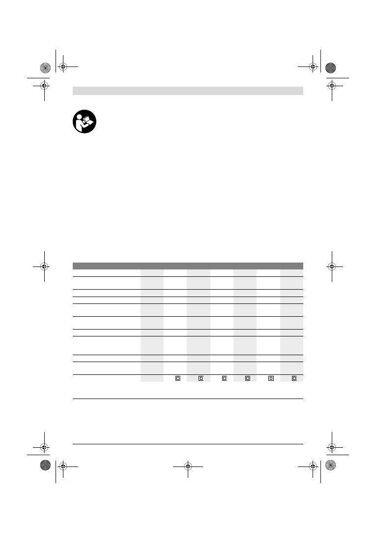
Latviešu |
137
Bosch Power Tools
1 619 929 J37 | (2.2.12)
Izstrādājuma un tā darbības apraksts
Uzmanīgi izlasiet visus drošības
noteikumus.
Šeit sniegto drošības noteikumu
un norādījumu neievērošana var izraisīt
aizdegšanos un būt par cēloni elektriskajam
triecienam vai nopietnam savainojumam.
Lūdzam atvērt atlokāmo lappusi ar elektroinstrumenta attēlu
un turēt to atvērtu visu laiku, kamēr tiek lasīta lietošanas
pamācība.
Pielietojums
Instruments ir paredzēts koka, plastmasas, pildvielu, kā arī
lakotu virsmu sausai slīpēšanai.
Attēlotās sastāvdaļas
Attēloto sastāvdaļu numerācija atbilst numuriem elektroin-
strumenta attēlā, kas sniegts ilustratīvajā lappusē.
1
Papildrokturis (ar izolētu noturvirsmu)*
2
Skrūve papildroktura stiprināšanai*
3
Regulators svārstību biežuma iestādīšanai
(GSS 230 AE/GSS 280 AE)
4
Ieslēdzējs
5
Taustiņš ieslēdzēja fiksēšanai
6
Putekļu konteiners salikumā (Microfilter System)*
7
Sešstūra stieņatslēga
8
Fiksējošā svira
9
Slīpēšanas pamatne
10
Piespiedējspaile
11
Rokturis (ar izolētu noturvirsmu)
12
Putekļu konteinera turētājs*
13
Plastmasas bīdnis
14
Putekļu uzsūkšanas kanāla īscaurule
15
Putekļu konteinera fiksators*
16
Filtrējošais elements (Microfilter System)*
17
Uzsūkšanas adapters*
18
Uzsūkšanas šļūtene*
19
Slīploksne*
20
Caurumotājs*
21
Skrūves slīpēšanas pamatnes stiprināšanai
22
Slīpēšanas pamatne, plāna, pagarināta*
23
Slīpēšanas pamatne, pagarināta*
24
Skrūves pagarinātajai slīpēšanas pamatnei*
25
Slīpēšanas pamatne, trijstūra veida*
26
Slīpēšanas pamatne, trijstūra veida, pagarināta*
*Šeit attēlotie vai aprakstītie piederumi neietilpst standarta
piegādes komplektā. Pilns pārskats par izstrādājuma
piederumiem ir sniegts mūsu piederumu katalogā.
Tehniskie parametri
Informācija par troksni un vibrāciju
Trokšņa parametru vērtības ir noteiktas atbilstoši standartam
EN 60745.
Elektroinstrumenta radītā pēc raksturlīknes A izsvērtā
trokšņa skaņas spiediena tipiskais līmenis ir 76 dB(A).
Izkliede K=3 dB.
Trokšņa līmenis darba laikā var pārsniegt 80 dB(A).
Izmantojiet ausu aizsargus!
Kopējā vibrācijas paātrinājuma vērtība a
h
(vektoru summa
trijos virzienos) un izkliede K ir noteikta atbilstoši standartam
EN 60745.
a
h
=4,5 m/s
2
, K=1,5 m/s
2
.
Orbitālā slīpmašīna
GSS ...
230 A
230 AE
230 AE
280 A
280 AE
280 AE
Izstrādājuma numurs
0 601 ...
292 0..
292 7..
292 6..
293 0..
293 7..
293 6..
Putekļu konteiners piegādes
komplektā
–
–
z
–
–
z
Svārstību biežuma iestādīšana
–
z
z
–
z
z
Nominālā patērējamā jauda
W
300
300
300
330
330
330
Griešanās ātrums vai kustību
biežums
min.
-1
11000
5500
–
11000
5500
–
11000
11000
5500
–
11000
5500
–
11000
Svārstību biežums brīvgaitā
min.
-1
22000
11000
–
22000
11000
–
22000
22000
11000
–
22000
11000
–
22000
Svārstību diametrs
mm
2,4
2,4
2,4
2,4
2,4
2,4
Slīpēšanas lokšņu izmēri
—
ar mikroāķu pārklājumu
—
stiprināšanai piespiedējspailēs
mm
mm
93 x 185
93 x 230
93 x 185
93 x 230
93 x 185
93 x 230
115 x 230
115 x 280
115 x 230
115 x 280
115 x 230
115 x 280
Slīpēšanas pamatnes izmēri
mm
92 x 182
92 x 182
92 x 182 114 x 226 114 x 226 114 x 226
Svars atbilstoši EPTA-Procedure
01/2003
kg
2,3
2,3
2,3
2,6
2,6
2,6
Elektroaizsardzības klase
/
II
/
II
/
II
/
II
/
II
/
II
Šādi parametri tiek nodrošināti pie nominālā elektrobarošanas sprieguma [U] 230 V. Iekārtām, kas paredzētas citam spriegumam vai ir modificētas
atbilstoši nacionālajiem standartiem, šie parametri var atšķirties.
Lūdzam vadīties pēc elektroinstrumenta izstrādājuma numura. Atsevišķiem izstrādājumiem tirdzniecības apzīmējumi var mainīties.
OBJ_BUCH-426-005.book Page 137 Thursday, February 2, 2012 10:06 AM
138
| Latviešu
1 619 929 J37 | (2.2.12)
Bosch Power Tools
Šajā pamācībā norādītais vibrācijas līmenis ir izmērīts atbils-
toši standartā EN 60745 noteiktajai procedūrai un var tikt lie-
tots instrumentu salīdzināšanai. To var izmantot arī vibrācijas
radītās papildu slodzes iepriekšējai novērtēšanai.
Šeit norādītais vibrācijas līmenis ir attiecināms uz elektroin-
strumenta galvenajiem pielietojuma veidiem. Ja elektroin-
struments tiek lietots netipiskiem mērķiem, kopā ar netipis-
kiem darbinstrumentiem vai nav vajadzīgajā veidā apkalpots,
tā vibrācijas līmenis var atšķirties no šeit sniegtās vērtības.
Tas var ievērojami palielināt vibrācijas radīto papildu slodzi
zināmam darba laika posmam.
Lai precīzi izvērtētu vibrācijas radīto papildu slodzi zināmam
darba laika posmam, jāņem vērā arī laiks, kad elektroinstru-
ments ir izslēgts vai arī darbojas, taču reāli netiek izmantots
paredzētā darba veikšanai. Tas var ievērojami samazināt vib-
rācijas radīto papildu slodzi zināmam darba laika posmam.
Veiciet papildu pasākumus, lai pasargātu strādājošo personu
no vibrācijas kaitīgās iedarbības, piemēram, savlaicīgi veiciet
elektroinstrumenta un darbinstrumentu apkalpošanu, novēr-
siet roku atdzišanu un pareizi plānojiet darbu.
Atbilstības deklarācija
Mēs ar pilnu atbildību paziņojam, ka sadaļā „Tehniskie
parametri“ aprakstītais izstrādājums atbilst šādiem
standartiem vai normatīvajiem dokumentiem: EN 60745, kā
arī direktīvām 2011/65/ES, 2004/108/EK un 2006/42/EK.
Tehniskā lieta (2006/42/EK) no:
Robert Bosch GmbH, PT/ETM9,
D-70745 Leinfelden-Echterdingen
Robert Bosch GmbH, Power Tools Division
D-70745 Leinfelden-Echterdingen
12.01.2012
Montāža
f
Pirms elektroinstrumenta apkopes vai apkalpošanas
izvelciet tā elektrokabeļa kontaktdakšu no barojošā
elektrotīkla kontaktligzdas.
Putekļu un skaidu uzsūkšana
f
Dažu materiālu, piemēram, svinu saturošu krāsu, dažu
koksnes šķirņu, minerālu un metālu putekļi var būt kaitīgi
veselībai. Pieskaršanās šādiem putekļiem vai to
ieelpošana var izraisīt alerģiskas reakcijas vai elpošanas
ceļu saslimšanu elektroinstrumenta lietotājam vai darba
vietai tuvumā esošajām personām.
Atsevišķu materiālu putekļi, piemēram, putekļi, kas rodas,
zāģējot ozola vai dižskābarža koksni, var izraisīt vēzi, īpaši
tad, ja koksne iepriekš ir tikusi ķīmiski apstrādāta (ar hro-
mātu vai koksnes aizsardzības līdzekļiem). Azbestu
saturošus materiālus drīkst apstrādāt vienīgi personas ar
īpašām profesionālām iemaņām.
–
Pielietojiet apstrādājamajam materiālam vispiemēro-
tāko putekļu uzsūkšanas metodi.
–
Darba vietai jābūt labi ventilējamai.
–
Darba laikā ieteicams izmantot masku elpošanas ceļu
aizsardzībai ar filtrēšanas klasi P2.
Ievērojiet jūsu valstī spēkā esošos priekšrakstus, kas
attiecas uz apstrādājamo materiālu.
f
Nepieļaujiet putekļu uzkrāšanos darba vietā.
Putekļi var
viegli aizdegties.
Putekļu uzsūkšana, uzkrājot tos konteinerā
(skatīt attēlus A1
–
A4)
Pirms putekļu konteinera
6
pievienošanas izvelciet
plastmasas bīdni
13
. Uzbīdiet putekļu konteineru
6
uz
putekļu uzsūkšanas kanāla īscaurules
14
, līdz tas fiksējas.
Sekojiet, lai plastmasas bīdnis
13
ievietotos turētājā
12
.
Lai iztukšotu putekļu konteineru
6
, nospiediet fiksatoru
15
konteinera virzienā (
n
). Pavelciet putekļu konteineru lejup,
līdz tas atdalās no īscaurules (
o
).
Pirms putekļu konteinera
6
atvēršanas ieteicams pāris reizes
uzsist ar to pa cietu virsmu, kā parādīts attēlā, šādi atbrīvojot
putekļus, kas pielipuši filtrējošajam elementam.
Turot putekļu konteineru
6
aiz fiksējošajiem atvērumiem,
paceliet filtrējošo elementu
16
augšup, izņemiet to un
iztukšojiet konteineru. Attīriet filtrējošā elementa
16
ieloces
no putekļiem, lietojot mīkstu suku.
Putekļu uzsūkšana ar ārējā putekļsūcēja palīdzību
(attēls B)
Uzbīdiet uzsūkšanas adapteru
17
uz putekļu uzsūkšanas
kanāla īscaurules
14
. Sekojiet, lai adaptera fiksatori droši
noturētu to uz īscaurules. Uzsūkšanas adapteram
17
var
pievienot šļūteni ar diametru 19 mm.
Lai noņemtu uzsūkšanas adapteru
17
, saspiediet kopā abus
tā fiksatorus un novelciet adapteru no putekļu uzsūkšanas
kanāla īscaurules.
Putekļsūcējam jābūt piemērotam apstrādājamā materiāla
putekļu uzsūkšanai.
Veselībai īpaši kaitīgu, kancerogēnu vai sausu putekļu
uzsūkšanai lietojiet speciālus putekļsūcējus.
Slīploksnes nomaiņa
Pirms jaunas slīploksnes iestiprināšanas notīriet netīrumus
un putekļus no slīpēšanas pamatnes
9
, piemēram, ar otu.
Lai nodrošinātu optimālu putekļu uzsūkšanu, sekojiet, lai
putekļu aizvadīšanas atvērumi slīploksnē sakristu ar
urbumiem slīpēšanas pamatnē.
Slīpēšanas loksnes ar mikroāķu pārklājumu (attēls C)
Slīpēšanas pamatne
9
ir pārklāta ar mikroāķu materiālu, kas
ļauj uz tās ātri un vienkārši nostiprināt slīploksnes ar mikroāķu
pārklājumu.
Ar vieglu sitienu attīriet slīpēšanas pamatnes
9
pārklājumu no
putekļiem pirms slīploksnes
19
iestiprināšanas, šādi panākot
optimālu satveri.
Novietojiet slīploksni
19
ar vienu tās pusi uz slīpēšanas
pamatnes
9
un stingri piespiediet, panākot, lai slīploksne
cieši piegultu pamatnei.
Lai noņemtu slīploksni
19
, satveriet to aiz viena stūra un
atraujiet no slīpēšanas pamatnes
9
.
Dr. Egbert Schneider
Senior Vice President
Engineering
Dr. Eckerhard Strötgen
Engineering Director
PT/ESI
OBJ_BUCH-426-005.book Page 138 Thursday, February 2, 2012 10:06 AM
Latviešu |
139
Bosch Power Tools
1 619 929 J37 | (2.2.12)
Slīpēšanas loksnes bez pašnoturošā pārklājuma (attēls D)
Nedaudz paceliet piespiedējspaiļu fiksējošās sviras
8
un
atāķējiet tās.
Līdz galam pabīdiet slīpēšanas loksnes
19
galu zem atvērtās
aizmugurējās piespiedējspailes
10
un iestipriniet slīpēšanas
loksni, ieāķējot fiksējošo sviru
8
.
Līdzeni noguldiet slīpēšanas loksni
19
uz slīpēšanas
pamatnes. Pabīdiet slīpēšanas loksnes
19
otru galu zem
atvērtās priekšējās piespiedējspailes
10
un iestipriniet
slīpēšanas loksni, ieāķējot fiksējošo sviru
8
.
Neperforētajās slīpēšanas loksnēs, kas tiek piegādātas,
piemēram, rulonos vai liela izmēra lokšņu veidā, vajadzīgos
atvērumus var izveidot, lietojot caurumotāju
20
. Šim nolūkam
piespiediet elektroinstrumentu ar uz tā nostiprinātu
slīpēšanas loksni pie caurumotāja (skatīt attēlu E).
Lai izņemtu slīpēšanas loksni
19
, atbrīvojiet piespiedējspaiļu
8
fiksējošās sviras un izvelciet slīpēšanas loksni.
Slīplokšņu izvēle
Lietotājam ir iespējams izvēlēties dažādu šķirņu slīploksnes,
atkarībā no apstrādājamā materiāla un vēlamā virsmas
apstrādes ātruma.
Slīpēšanas pamatnes nomaiņa (attēls F)
Vajadzības gadījumā slīpēšanas pamatni
9
var nomainīt.
Pilnīgi izskrūvējiet 6 skrūves
21
un noņemiet slīpēšanas
pamatni
9
. Novietojiet uz instrumenta jaunu slīpēšanas
pamatni
9
un stingri pieskrūvējiet skrūves.
Īpašās slīpēšanas pamatnes
Kopā ar instrumentu piegādāto slīpēšanas pamatni
9
var
nomainīt pret kādu no īpašajām slīpēšanas pamatnēm, ko var
iegādāties kā papildpiederumu.
Īpašās slīpēšanas pamatnes ir iestiprināmas instrumentā
tāpat, kā kopā ar instrumentu piegādātā slīpēšanas pamatne.
Īpašajām slīpēšanas pamatnēm piemērotās slīploksnes ir
nostiprināmas un noņemamas tāpat, kā oriģinālās
slīploksnes.
Pagarinātā slīpēšanas pamatne, taisnstūrveida, plāna
(GSS 230 A/GSS 230 AE) (attēls G)
Taisnstūrveida plānā, pagarinātā slīpēšanas pamatne
22
ļauj
veikt slīpēšanu grūti pieejamās vietās un šaurās starptelpās,
piemēram, logu un durvju žalūzijas, gropes vai virsmas aiz
radiatoriem un ūdensvada caurulēm.
Lai nostiprinātu taisnstūrveida plāno, pagarināto slīpēšanas
pamatni
22
, lietojiet šim nolūkam paredzētās skrūves
24
.
Pagarinātā slīpēšanas pamatne, trijstūrveida
(GSS 230 A/GSS 230 AE) (attēls H)
Trijstūrveida pagarinātā slīpēšanas pamatne
26
ļauj ērti
noslīpēt stūrus un malas.
Smalkslīpēšanas pamatne (bez mikroāķu pārklājuma)
(GSS 230 AE/GSS 280 AE) (attēls D)
Pārsvarā izmantojot standarta slīpēšanas loksnes bez
mikroāķu pārklājuma, ieteicams lietot smalkslīpēšanas
pamatni bez mikroāķu pārklājuma. Šīs pamatnes plakanā
virsma ļauj panākt optimālus slīpēšanas rezultātus, veicot
virsmu smalko apstrādi.
Papildrokturis
Papildrokturis
1
ļauj ērti turēt instrumentu un nodrošina
optimālu svara sadalījumu, īpaši tad, ja jāpanāk augsta
slīpēšanas ražība.
Pieskrūvējiet papildrokturi
1
ar skrūvi
2
pie instrumenta
korpusa.
Lietošana
Uzsākot lietošanu
f
Pievadiet instrumentam pareizu spriegumu!
Spriegumam elektrotīklā jāatbilst vērtībai, kas
norādīta instrumenta marķējuma plāksnītē. Elektro-
instrumenti, kas paredzēti 230 V spriegumam, var
darboties arī no 220 V elektrotīkla.
Ieslēgšana un izslēgšana
Lai
ieslēgtu
elektroinstrumentu, nospiediet ieslēdzēju
4
un
turiet to nospiestu.
Lai nospiesto ieslēdzēju
4
nostiprinātu ieslēgtā stāvoklī
,
nospiediet ieslēdzēja fiksēšanas taustiņu
5
.
Lai
izslēgtu
elektroinstrumentu, atlaidiet ieslēdzēju
4
vai arī,
ja tas ir nostiprināts ar fiksēšanas taustiņa
5
palīdzību,
īslaicīgi nospiediet un atlaidiet ieslēdzēju
4
.
Graudainība
40
–
400
Jebkura veida koksnes
apstrādei
Priekšslīpēšanai, piemēram,
raupju, neēvelētu siju un dēļu
apstrādei
rupja
40, 60
Plakanu virsmu slīpēšanai un
nelielu nelīdzenumu
nogludināšanai
vidēja
80, 100, 120
Cietas koksnes galīgajai apdarei
un smalkslīpēšanai
smalka
180, 240,
320, 400
40
–
320
Krāsas un lakas pārklājumu vai
gruntējuma slāņu, piemēram,
pildvielu un špaktelējumu
apstrādei
Krāsas noslīpēšanai
rupja
40, 60
Priekškrāsojuma slīpēšanai
vidēja
80, 100, 120
Gruntējuma slāņu galīgajai
noslīpēšanai pirms lakošanas
smalka
180, 240, 320
OBJ_BUCH-426-005.book Page 139 Thursday, February 2, 2012 10:06 AM
140
| Lietuviškai
1 619 929 J37 | (2.2.12)
Bosch Power Tools
Svārstību biežuma iestādīšana (GSS 230 AE/GSS 280 AE)
Ar svārstību biežuma regulatoru
3
var iestādīt vēlamo darbin-
strumenta svārstību biežumu (tas iespējams arī elektroin-
strumenta darbības laikā).
Optimālais svārstību biežums ir atkarīgs no apstrādājamā
materiāla un darba apstākļiem, un to ieteicams noteikt
praktisku mēģinājumu ceļā.
Norādījumi darbam
f
Pirms elektroinstrumenta novietošanas nogaidiet, līdz
apstājas tā kustīgās daļas.
Instrumenta slīpēšanas ātrums ir atkarīgs galvenokārt no
iestiprinātās slīpēšanas loksnes un no izvēlētā orbitālo
kustību biežuma (GSS 230 AE/GSS 280 AE).
Vienīgi nevainojamas kvalitātes slīplokšņu lietošana spēj
nodrošināt augstu slīpēšanas ražību, vienlaikus saudzējot
elektroinstrumentu.
Lai palielinātu slīplokšņu kalpošanas ilgumu, darba laikā
ieturiet mērenu, pastāvīgu spiedienu uz apstrādājamo
virsmu.
Pārlieku liels spiediens uz apstrādājamo virsmu nenodrošina
augstu slīpēšanas ražību, bet gan izsauc elektroinstrumenta
un slīploksnes priekšlaicīgu nolietošanos.
Neizmantojiet citu materiālu apstrādei slīploksni, kas lietota
metāla slīpēšanai.
Lietojiet vienīgi oriģinālos slīpēšanas piederumus, kas ražoti
firmā Bosch.
Apkalpošana un apkope
Apkalpošana un tīrīšana
f
Pirms elektroinstrumenta apkopes vai apkalpošanas
izvelciet tā elektrokabeļa kontaktdakšu no barojošā
elektrotīkla kontaktligzdas.
f
Lai nodrošinātu ilgstošu un nevainojamu elektroin-
strumenta darbību, uzturiet tīru tā korpusu un
ventilācijas atveres.
Ja nepieciešams nomainīt elektrotīkla kabeli, tas jāveic firmas
Bosch elektroinstrumentu servisa centrā vai Bosch pilnvarotā
elektroinstrumentu remonta darbnīcā, jo tā tiks saglabāts
vajadzīgais darba drošības līmenis.
Ja, neraugoties uz augsto izgatavošanas kvalitāti un rūpīgo
pēcražošanas pārbaudi, elektroinstruments tomēr sabojājas,
tas nogādājams remontam firmas Bosch pilnvarotā
elektroinstrumentu remonta darbnīcā.
Pieprasot konsultācijas un pasūtot rezerves daļas, noteikti
paziņojiet 10 zīmju izstrādājuma numuru, kas atrodams uz
elektroinstrumenta marķējuma plāksnītes.
Tehniskā apkalpošana un konsultācijas klientiem
Klientu apkalpošanas dienests atbildēs uz Jūsu jautājumiem
par izstrādājumu remontu un apkalpošanu, kā arī par to
rezerves daļām. Kopsalikuma attēlus un informāciju par
rezerves daļām var atrast arī interneta vietnē:
www.bosch-pt.com
Bosch klientu konsultāciju grupa centīsies Jums palīdzēt
vislabākajā veidā, atbildot uz jautājumiem par izstrādājumu
un to piederumu iegādi, lietošanu un regulēšanu.
Latvijas Republika
Robert Bosch SIA
Bosch elektroinstrumentu servisa centrs
Dzelzavas ielā 120 S
LV-1021 Rīga
Tālr.: + 371 67 14 62 62
Telefakss: + 371 67 14 62 63
E-pasts: service-pt@lv.bosch.com
Atbrīvošanās no nolietotajiem izstrādājumiem
Nolietotie elektroinstrumenti, to piederumi un iesaiņojuma
materiāli jānogādā otrreizējai pārstrādei apkārtējai videi
nekaitīgā veidā.
Neizmetiet elektroinstrumentu sadzīves atkritumu tvertnē!
Tikai ES valstīm
Saskaņā ar Eiropas Savienības direktīvu
2002/96/EK par nolietotajām
elektriskajām un elektroniskajām ierīcēm
un šīs direktīvas atspoguļojumiem
nacionālajā likumdošanā, lietošanai nederī-
gie elektroinstrumenti jāsavāc atsevišķi un
jānogādā otrreizējai pārstrādei apkārtējai videi nekaitīgā
veidā.
Tiesības uz izmaiņām tiek saglabātas.
Lietuviškai
Saugos nuorodos
Bendrosios darbo su elektriniais įrankiais saugos
nuorodos
Perskaitykite visas šias saugos
nuorodas ir reikalavimus.
Jei
nepaisysite žemiau pateiktų saugos nuorodų ir reikalavimų,
gali trenkti elektros smūgis, kilti gaisras ir galite sunkiai
susižaloti arba sužaloti kitus asmenis.
Išsaugokite šias saugos nuorodas ir reikalavimus, kad ir
ateityje galėtumėte jais pasinaudoti.
Toliau pateiktame tekste vartojama sąvoka „Elektrinis įrankis“
apibūdina įrankius, maitinamus iš elektros tinklo (su
maitinimo laidu), ir akumuliatorinius įrankius (be maitinimo
laido).
Darbo vietos saugumas
f
Darbo vieta turi būti švari ir gerai apšviesta.
Netvarkinga arba blogai apšviesta darbo vieta gali tapti
nelaimingų atsitikimų priežastimi.
f
Nedirbkite su elektriniu įrankiu aplinkoje, kurioje yra
degių skysčių, dujų ar dulkių.
Elektriniai įrankiai gali
kibirkščiuoti, o nuo kibirkščių dulkės arba susikaupę garai
gali užsidegti.
OBJ_BUCH-426-005.book Page 140 Thursday, February 2, 2012 10:06 AM

Lietuviškai |
141
Bosch Power Tools
1 619 929 J37 | (2.2.12)
f
Dirbdami su elektriniu įrankiu neleiskite šalia būti
žiūrovams, vaikams ir lankytojams.
Nukreipę dėmesį į
kitus asmenis galite nebesuvaldyti prietaiso.
Elektrosauga
f
Elektrinio įrankio maitinimo laido kištukas turi atitikti
tinklo kištukinio lizdo tipą. Kištuko jokiu būdu negali-
ma modifikuoti. Nenaudokite kištuko adapterių su
įžemintais elektriniais įrankiais.
Originalūs kištukai, tiks-
liai tinkantys elektros tinklo kištukiniam lizdui, sumažina
elektros smūgio pavojų.
f
Saugokitės, kad neprisiliestumėte prie įžemintų pa-
viršių, pvz., vamzdžių, šildytuvų, viryklių ar šaldytuvų.
Kai jūsų kūnas yra įžemintas, padidėja elektros smūgio ri-
zika.
f
Saugokite elektrinį įrankį nuo lietaus ir drėgmės.
Jei į
elektrinį įrankį patenka vandens, padidėja elektros smūgio
rizika.
f
Nenaudokite maitinimo laido ne pagal paskirtį, t.y. ne-
neškite elektrinio įrankio paėmę už laido, nekabinkite
ant laido, netraukite už jo, jei norite iš kištukinio lizdo
ištraukti kištuką. Laidą patieskite taip, kad jo neveiktų
karštis, jis neišsiteptų alyva ir jo nepažeistų aštrios de-
talės ar judančios prietaiso dalys.
Pažeisti arba susipynę
laidai gali tapti elektros smūgio priežastimi.
f
Jei su elektriniu įrankiu dirbate lauke, naudokite tik to-
kius ilginamuosius laidus, kurie tinka ir lauko darbams.
Naudojant lauko darbams pritaikytus ilginamuosius laidus,
sumažėja elektros smūgio pavojus.
f
Jei su elektriniu įrankiu neišvengiamai reikia dirbti
drėgnoje aplinkoje, naudokite nuotėkio srovės saugi-
klį.
Dirbant su nuotėkio srovės saugikliu sumažėja elektros
smūgio pavojus.
Žmonių sauga
f
Būkite atidūs, sutelkite dėmesį į tai, ką jūs darote ir,
dirbdami su elektriniu įrankiu, vadovaukitės sveiku
protu. Nedirbkite su elektriniu įrankiu, jei esate
pavargę arba vartojote narkotikų, alkoholio ar medika-
mentų.
Akimirksnio neatidumas dirbant su elektriniu
įrankiu gali tapti sunkių sužalojimų priežastimi.
f
Visada dirbkite su asmens apsaugos priemonėmis ir
apsauginiais akiniais.
Naudojant asmens apsaugos
priemones, pvz., respiratorių ar apsauginę kaukę, neslys-
tančius batus, apsauginį šalmą, klausos apsaugos
priemones ir kt., rekomenduojamas atitinkamai pagal
naudojamą elektrinį įrankį, sumažėja rizika susižeisti.
f
Saugokitės, kad elektrinio įrankio neįjungtumėte atsi-
tiktinai. Prieš prijungdami elektrinį įrankį prie elektros
tinklo ir/arba akumuliatoriaus, prieš pakeldami ar
nešdami įsitikinkite, kad jis yra išjungtas.
Jeigu nešda-
mi elektrinį įrankį pirštą laikysite ant jungiklio arba prietai-
są įjungsite į elektros tinklą, kai jungiklis yra įjungtas, gali
įvykti nelaimingas atsitikimas.
f
Prieš įjungdami elektrinį įrankį pašalinkite reguliavimo
įrankius arba veržlinius raktus.
Prietaiso besisukančioje
dalyje esantis įrankis ar raktas gali sužaloti.
f
Stenkitės, kad kūnas visada būtų normalioje padėtyje.
Dirbdami stovėkite saugiai ir visada išlaikykite pusiau-
svyrą.
Tvirtai stovėdami ir gerai išlaikydami pusiausvyrą
galėsite geriau kontroliuoti elektrinį įrankį netikėtose situa-
cijose.
f
Dėvėkite tinkamą aprangą. Nedėvėkite plačių drabužių
ir papuošalų. Saugokite plaukus, drabužius ir pirštines
nuo besisukančių elektrinio įrankio dalių.
Laisvus dra-
bužius, papuošalus bei ilgus plaukus gali įtraukti besisu-
kančios dalys.
f
Jei yra numatyta galimybė prijungti dulkių nusiurbimo
ar surinkimo įrenginius, visada įsitikinkite, ar jie yra
prijungti ir ar tinkamai naudojami.
Naudojant dulkių
nusiurbimo įrenginius sumažėja kenksmingas dulkių
poveikis.
Rūpestinga elektrinių įrankių priežiūra ir naudojimas
f
Neperkraukite prietaiso. Naudokite jūsų darbui
tinkamą elektrinį įrankį.
Su tinkamu elektriniu įrankiu jūs
dirbsite geriau ir saugiau, jei neviršysite nurodyto
galingumo.
f
Nenaudokite elektrinio įrankio su sugedusiu jungikliu.
Elektrinis įrankis, kurio nebegalima įjungti ar išjungti, yra
pavojingas ir jį reikia remontuoti.
f
Prieš reguliuodami prietaisą, keisdami darbo įrankius
ar prieš valydami prietaisą, iš elektros tinklo lizdo
ištraukite kištuką ir/arba išimkite akumuliatorių.
Ši
atsargumo priemonė apsaugos jus nuo netikėto elektrinio
įrankio įsijungimo.
f
Nenaudojamą elektrinį įrankį sandėliuokite vaikams ir
nemokantiems juo naudotis asmenims neprieinamoje
vietoje.
Elektriniai įrankiai yra pavojingi, kai juos naudoja
nepatyrę asmenys.
f
Rūpestingai prižiūrėkite elektrinį įrankį. Patikrinkite,
ar besisukančios prietaiso dalys tinkamai veikia ir
niekur nestringa, ar nėra sulūžusių ar pažeistų dalių,
kurios trikdytų elektrinio įrankio veikimą. Prieš vėl
naudojant prietaisą, pažeistos prietaiso dalys turi būti
sutaisytos.
Daugelio nelaimingų atsitikimų priežastis yra
blogai prižiūrimi elektriniai įrankiai.
f
Pjovimo įrankiai turi būti aštrūs ir švarūs.
Rūpestingai
prižiūrėti pjovimo įrankiai su aštriomis pjaunamosiomis
briaunomis mažiau stringa ir juos yra lengviau valdyti.
f
Elektrinį įrankį, papildomą įrangą, darbo įrankius ir t.t.
naudokite taip, kaip nurodyta šioje instrukcijoje, ir
atsižvelkite į darbo sąlygas ir atliekamą darbą.
Naudojant elektrinius įrankius ne pagal paskirtį, gali
susidaryti pavojingos situacijos.
Aptarnavimas
f
Elektrinį įrankį turi remontuoti tik kvalifikuoti
specialistai ir naudoti tik originalias atsargines dalis.
Taip galima garantuoti, jog elektrinis įrankis išliks saugus
naudoti.
OBJ_BUCH-426-005.book Page 141 Thursday, February 2, 2012 10:06 AM
142
| Lietuviškai
1 619 929 J37 | (2.2.12)
Bosch Power Tools
Saugos nuorodos dirbantiems su šlifuokliais
f
Prietaisą leidžiama naudoti tik šlifavimui sausuoju
būdu.
Į prietaisą patekęs vanduo padidina elektros smūgio
riziką.
f
Dėmesio, gaisro pavojus! Venkite šlifuojamos
medžiagos ir prietaiso įkaitimo, prieš darydami
pertrauką, ištuštinkite dulkių surinkimo konteinerį.
Šlifavimo dulkės, esančios dulkių surinkimo maišelyje,
mikrofiltro sistemoje, popieriniame maišelyje (arba filtro
maišelyje, pvz., dulkių siurblyje) esant tam tikroms
sąlygoms, pavyzdžiui, metalo šlifavimo metu lekiant
kibirkštims, gali savaime užsiliepsnoti. Tai gali būti ypač
pavojinga tuo atveju, kai dulkės yra susimaišiusios su lako,
poliuretano dalelėmis arba kitomis cheminėmis
medžiagomis, o taip pat, kuomet nušlifuota medžiagos
masė yra įkaitusi.
f
Darbo metu elektrinį įrankį visuomet būtina laikyti
abiem rankomis ir patikimai stovėti.
Elektrinis įrankis
yra saugiau valdomas, kai laikomas dviem rankomis.
f
Įtvirtinkite ruošinį.
Tvirtinimo įranga arba spaustuvais
įtvirtintas ruošinys yra užfiksuojamas žymiai patikimiau nei
laikant ruošinį ranka.
Gaminio ir techninių duomenų aprašas
Perskaitykite visas šias saugos nuorodas ir
reikalavimus.
Jei nepaisysite žemiau
pateiktų saugos nuorodų ir reikalavimų, gali
trenkti elektros smūgis, kilti gaisras ir galite
sunkiai susižaloti arba sužaloti kitus asmenis.
Atverskite lapą su elektrinio įrankio schema ir, skaitydami
instrukciją, palikite šį lapą atverstą.
Elektrinio įrankio paskirtis
Prietaisas yra skirtas medžiui, plastmasei, glaistui bei
lakuotiems paviršiams šlifuoti sausuoju būdu.
Pavaizduoti prietaiso elementai
Numeriais pažymėtus elektrinio įrankio elementus rasite šios
instrukcijos puslapiuose pateiktuose paveikslėliuose.
1
Papildoma rankena (izoliuotas rankenos paviršius)*
2
Papildomos rankenos varžtas*
3
Švytavimo judesių reguliatoriaus ratukas
(GSS 230 AE/GSS 280 AE)
4
Įjungimo-išjungimo jungiklis
5
Įjungimo-išjungimo jungiklio fiksatorius
6
Dulkių surinkimo dėžutė (Microfilter System)*
7
Šešiabriaunis raktas
8
Prispaudžiamasis lankelis
9
Šlifavimo plokštė
10
Prispaudžiamoji juostelė
11
Rankena (izoliuotas rankenos paviršius)
12
Dulkių surinkimo dėžutės laikiklis*
13
Plastikinis skląstis
14
Dulkių išmetimo atvamzdis
15
Dulkių surinkimo dėžutės fiksavimo svirtelė*
16
Filtruojamasis elementas (Microfilter System)*
17
Nusiurbimo adapteris*
18
Nusiurbimo žarna*
19
Šlifavimo popieriaus lapelis*
20
Įrankis skylėms pradurti*
21
Varžtai šlifavimo plokštei tvirtinti
22
Plona, pailginta šlifavimo plokštė*
23
Pailginta šlifavimo plokštė*
24
Pailgintos šlifavimo plokštės varžtai*
25
Trikampis popieriaus lapelis*
26
Pailginta trikampė šlifavimo plokštė*
*Pavaizduoti ar aprašyti priedai į tiekiamą standartinį komplektą
neįeina. Visą papildomą įrangą rasite mūsų papildomos įrangos
programoje.
Techniniai duomenys
Vibracinis šlifuoklis
GSS ...
230 A
230 AE
230 AE
280 A
280 AE
280 AE
Gaminio numeris
0 601 ...
292 0..
292 7..
292 6..
293 0..
293 7..
293 6..
Dulkių surinkimo dėžutė tiekiamame
komplekte
–
–
z
–
–
z
Šlifavimo judesių skaičiaus
nustatymas
–
z
z
–
z
z
Nominali naudojamoji galia
W
300
300
300
330
330
330
Tuščiosios eigos sūkių skaičius
min
-1
11000
5500
–
11000
5500
–
11000
11000
5500
–
11000
5500
–
11000
Tuščiosios eigos švytavimo judesių
skaičius
min
-1
22000
11000
–
22000
11000
–
22000
22000
11000
–
22000
11000
–
22000
Švytavimo trajektorijos spindulys
mm
2,4
2,4
2,4
2,4
2,4
2,4
Duomenys galioja tik tada, kai nominalioji įtampa [U] 230 V. Jei įtampa kitokia arba jei naudojamas specialus, tam tikrai šaliai gaminamas modelis, šie
duomenys gali skirtis.
Atkreipkite dėmesį į jūsų elektrinio įrankio gaminio numerį, nes kai kurių elektrinių įrankių modelių pavadinimai gali skirtis.
OBJ_BUCH-426-005.book Page 142 Thursday, February 2, 2012 10:06 AM
Lietuviškai |
143
Bosch Power Tools
1 619 929 J37 | (2.2.12)
Informacija apie triukšmą ir vibraciją
Triukšmo matavimų vertės nustatytos pagal EN 60745.
Pagal A skalę išmatuotas prietaiso garso slėgio lygis tipiniu
atveju siekia 76 dB(A). Paklaida K=3 dB.
Triukšmo lygis dirbant su prietaisu gali viršyti 80 dB(A).
Dirbkite su klausos apsaugos priemonėmis!
Vibracijos bendroji vertė a
h
(trijų krypčių atstojamasis vekto-
rius) ir paklaida K nustatytos pagal EN 60745:
a
h
=4,5 m/s
2
, K=1,5 m/s
2
.
Šioje instrukcijoje pateiktas vibracijos lygis buvo išmatuotas
pagal EN 60745 normoje standartizuotą matavimo metodą, ir
lyginant elektrinius įrankius jį galima naudoti. Jis skirtas
vibracijos poveikiui laikinai įvertinti.
Nurodytas vibracijos lygis atspindi pagrindinius elektrinio
įrankio naudojimo atvejus. Tačiau jeigu elektrinis įrankis
naudojamas kitokiai paskirčiai, su kitokiais darbo įrankiais
arba jeigu jis nepakankamai techniškai prižiūrimas, vibracijos
lygis gali kisti. Tokiu atveju vibracijos poveikis per visą darbo
laikotarpį gali žymiai padidėti.
Norint tiksliai įvertinti vibracijos poveikį per tam tikrą darbo
laiką, reikia atsižvelgti ir į laiką, per kurį elektrinis įrankis buvo
išjungtas arba, nors ir veikė, bet nebuvo naudojamas. Tai
įvertinus, vibracijos poveikis per visą darbo laiką žymiai
sumažės.
Dirbančiajam nuo vibracijos poveikio apsaugoti paskirkite
papildomas apsaugos priemones, pvz.: elektrinių ir darbo
įrankių techninę priežiūrą, rankų šildymą, darbo eigos
organizavimą.
Atitikties deklaracija
Atsakingai pareiškiame, kad skyriuje „Techniniai duomenys“
aprašytas gaminys atitinka žemiau pateiktus standartus ir
norminius dokumentus: EN 60745 pagal Direktyvų
2011/65/ES, 2004/108/EB, 2006/42/EB reikalavimus.
Techninė byla (2006/42/EB) laikoma:
Robert Bosch GmbH, PT/ETM9,
D-70745 Leinfelden-Echterdingen
Robert Bosch GmbH, Power Tools Division
D-70745 Leinfelden-Echterdingen
12.01.2012
Montavimas
f
Prieš atliekant bet kokius elektrinio įrankio
reguliavimo ar priežiūros darbus reikia ištraukti
kištuką iš elektros tinklo lizdo.
Dulkių, pjuvenų ir drožlių nusiurbimas
f
Medžiagų, kurių sudėtyje yra švino, kai kurių rūšių me-
dienos, mineralų ir metalų dulkės gali būti kenksmingos
sveikatai. Dirbančiajam arba netoli esantiems asmenims
nuo sąlyčio su dulkėmis arba jų įkvėpus gali kilti alerginės
reakcijos, taip pat jie gali susirgti kvėpavimo takų ligomis.
Kai kurios dulkės, pvz., ąžuolo ir buko, yra vėžį sukelian-
čios, o ypač, kai mediena yra apdorota specialiomis medie-
nos priežiūros priemonėmis (chromatu, medienos
apsaugos priemonėmis). Medžiagas, kuriose yra asbesto,
leidžiama apdoroti tik specialistams.
–
Jei yra galimybė, naudokite apdirbamai medžiagai
tinkančią dulkių nusiurbimo įrangą.
–
Pasirūpinkite geru darbo vietos vėdinimu.
–
Rekomenduojama dėvėti kvėpavimo takų apsauginę
kaukę su P2 klasės filtru.
Laikykitės jūsų šalyje galiojančių apdorojamoms
medžiagoms taikomų taisyklių.
f
Saugokite, kad darbo vietoje nesusikauptų dulkių.
Dulkės lengvai užsidega.
Vietinis nusiurbimas į dulkių surinkimo dėžutę
(žr. pav. A1
–
A4)
Prieš pradėdami montuoti dulkių surinkimo dėžutę
6
,
ištraukite plastikinį skląstį
13
. Stumkite dulkių surinkimo
dėžutę
6
ant dulkių išmetimo atvamzdžio
14
, kol ji
užsifiksuos. Stebėkite, kad plastikinis skląstis
13
įsistatytų
laikiklyje
12
.
Šlifavimo popieriaus lakšto
matmenys
—
su kibiuoju sujungimu
—
prispaudžiamas juostelėmis
mm
mm
93 x 185
93 x 230
93 x 185
93 x 230
93 x 185
93 x 230
115 x 230
115 x 280
115 x 230
115 x 280
115 x 230
115 x 280
Šlifavimo plokštės matmenys
mm
92 x 182
92 x 182
92 x 182 114 x 226 114 x 226 114 x 226
Svoris pagal „EPTA-Procedure
01/2003“
kg
2,3
2,3
2,3
2,6
2,6
2,6
Apsaugos klasė
/
II
/
II
/
II
/
II
/
II
/
II
Vibracinis šlifuoklis
GSS ...
230 A
230 AE
230 AE
280 A
280 AE
280 AE
Duomenys galioja tik tada, kai nominalioji įtampa [U] 230 V. Jei įtampa kitokia arba jei naudojamas specialus, tam tikrai šaliai gaminamas modelis, šie
duomenys gali skirtis.
Atkreipkite dėmesį į jūsų elektrinio įrankio gaminio numerį, nes kai kurių elektrinių įrankių modelių pavadinimai gali skirtis.
Dr. Egbert Schneider
Senior Vice President
Engineering
Dr. Eckerhard Strötgen
Engineering Director
PT/ESI
OBJ_BUCH-426-005.book Page 143 Thursday, February 2, 2012 10:06 AM
144
| Lietuviškai
1 619 929 J37 | (2.2.12)
Bosch Power Tools
Norėdami ištuštinti dulkių surinkimo dėžutę
6
, paspauskite
ant jos esančią fiksavimo svirtelę
15
(
n
). Patraukę žemyn,
nuimkite dulkių surinkimo dėžutę (
o
).
Prieš atidarant dulkių surinkimo dėžutę
6
rekomenduojama
nupurtyti dulkes nuo filtruojančio elemento, stuktelint dėžute
į kokį nors kietą pagrindą.
Suėmę dėžutę
6
už briaunų, nuimkite dangtelį su filtru
16
patraukdami jį įstrižai į viršų, ir ištuštinkite dėžutę.
Filtruojamojo elemento
16
klostes nuvalykite minkštu
šepetėliu.
Išorinis dulkių nusiurbimas (žr. pav. B)
Nusiurbimo adapterį
17
užmaukite ant išmetimo atvamzdžio
14
. Žiūrėkite, kad nusiurbimo adapterio fiksavimo svirtelės
užsifiksuotų. Prie nusiurbimo adapterio
17
galima prijungti
nusiurbimo žarną, kurios skersmuo yra 19 mm.
Norint nuimti nusiurbimo adapterį
17
, reikia suėmus už galų
suspausti abi fiksavimo svirteles ir adapterį nutraukti.
Dulkių siurblys turi būti pritaikytas apdirbamo ruošinio
pjuvenoms, drožlėms ir dulkėms nusiurbti.
Sveikatai ypač pavojingoms, vėžį sukeliančioms, sausoms
dulkėms nusiurbti būtina naudoti specialų dulkių siurblį.
Šlifavimo popieriaus keitimas
Prieš uždėdami naują šlifavimo popieriaus lapelį nuo šlifavimo
plokštės
9
, pašalinkite, pvz., teptuku, nešvarumus ir dulkes.
Norint, kad dulkių nusiurbimas vyktų optimaliai, skylės
šlifavimo popieriaus skritulyje turi sutapti su šlifavimo
plokštės kiaurymėmis.
Prikimbantys šlifavimo popieriaus lakštai (žr. pav. C)
Šlifavimo plokštė
9
turi kibų paviršių, prie kurio galima greitai
ir paprastai pritvirtinti kibius šlifavimo popieriaus lapelius.
Nukratykite dulkes nuo šlifavimo plokštės
9
prieš uždėdami
šlifavimo popieriaus lapelį
19
, tuomet lapelis prikibs tvirčiau.
Šlifavimo lapelį
19
pridėkite lygiai prie vieno šlifavimo
plokštės
9
krašto, tada šlifavimo lapelį uždėkite ant šlifavimo
plokštės ir tvirtai jį prispauskite.
Norėdami nuimti šlifavimo popieriaus lapelį
19
, suėmę už
kampelio atkelkite ir nuplėškite jį nuo šlifavimo plokštės
9
.
Neprikimbantys šlifavimo popieriaus lakštai (žr. pav. D)
Šiek tiek pakelkite prispaudžiamąjį lankelį
8
ir atkabinkite jį.
Stumkite šlifavimo popieriaus lapelį
19
iki atramos po atvira
užpakaline prispaudžiamąja juostele
10
ir, kad tvirtai
prispaustumėte šlifavimo popieriaus lapelį, užfiksuokite
prispaudžiamąjį lankelį
8
.
Šlifavimo popieriaus lapelį
19
įtempkite apie šlifavimo
plokštę. Stumkite kitą šlifavimo popieriaus lapelio
19
galą po
atvira priekine prispaudžiamąja juostele
10
ir, kad tvirtai
prispaustumėte šlifavimo popieriaus lapelį, užfiksuokite
prispaudžiamąjį lankelį
8
.
Šlifavimo popierių, kuriame nėra skylių, pvz. iš rulono, galima
pritaikyti darbui su dulkių nusiurbimo įranga, praduriant
skyles specialiu įrankiu
20
. Pritvirtinkite šlifavimo popieriaus
lakštą prie prietaiso ir, uždėję jį ant įrankio skylėms daryti,
prispauskite (žiūr. pav. E).
Norėdami nuimti šlifavimo popieriaus lakštą
19
, atlaisvinkite
prispaudžiamąjį lankelį
8
ir ištraukite šlifavimo popieriaus
lakštą.
Šlifavimo popieriaus pasirinkimas
Atsižvelgiant į šlifuojamos medžiagos rūšį ir norimą šlifavimo
efektyvumą galima pasirinkti įvairų šlifavimo popierių:
Šlifavimo plokštės keitimas (žr. pav. F)
Šlifavimo plokštę
9
, jei reikia, galima pakeisti.
Visiškai išsukite 6 varžtus
21
ir nuimkite šlifavimo plokštę
9
.
Uždėkite naują šlifavimo plokštę
9
ir vėl užveržkite varžtus.
Specialiosios šlifavimo plokštės
Jūs galite pakeisti komplekte esančią šlifavimo plokštę
9
specialia šlifavimo plokšte, kurią galima įsigyti kaip papildomą
įrangą.
Sumontuoti specialią šlifavimo plokštę galima analogiškai,
kaip ir komplekte esančiąją standartinę šlifavimo plokštę.
Nuimti ir uždėti šlifavimo popieriaus lapelį galima taip pat,
kaip ir originalųjį, tvirtinamą prie standartinės šlifavimo
plokštės.
Stačiakampė, plona, pailginta šlifavimo plokštė
(GSS 230 A/GSS 230 AE) (žr. pav. G)
Naudodami stačiakampę, ploną, pailgintą šlifavimo plokštę
22
galite šlifuoti sunkiai prieinamose vietose ir siauruose
tarpuose, pvz., langų ir durų juosteles, griovelius arba už
radiatorių ar vandentiekio vamzdžių.
Norėdami montuoti stačiakampę, ploną, pailgintą šlifavimo
plokštę
22
, naudokite specialius varžtus
24
.
Trikampė, pailginta šlifavimo plokštė
(GSS 230 A/GSS 230 AE) (žr. pav. H)
Naudodami trikampę, pailgintą šlifavimo plokštę
26
, galite
šlifuoti kampus ir briaunas.
Grūdėtumas
40
–
400
Visų rūšių medienai šlifuoti
Pirminiam šlifavimui,
pvz., šiurkščių, neobliuotų tąšų
bei lentų
grubus
40, 60
Lygioms plokštumoms šlifuoti ir
nedideliems nelygumams
išlyginti
vidutinis 80, 100, 120
Baigiamajam ir glotniajam
kietmedžio šlifavimui
smulkus 180, 240,
320, 400
40
–
320
Dažams ir lakams bei
gruntuotiems ir glaistytiems
paviršiams šlifuoti
Dažams pašalinti
grubus
40, 60
Gruntavimo dažams šlifuoti
vidutinis 80, 100, 120
Baigiamajam gruntavimo dažų ir
lako šlifavimui
smulkus 180, 240, 320
OBJ_BUCH-426-005.book Page 144 Thursday, February 2, 2012 10:06 AM
Lietuviškai |
145
Bosch Power Tools
1 619 929 J37 | (2.2.12)
Glotniojo šlifavimo plokštė (be kibiojo laikiklio)
(GSS 230 AE/GSS 280 AE) (žr. pav. D)
Jei dažniausiai naudojate standartinius šlifavimo popieriaus
lapelius, rekomenduojame naudoti glotniojo šlifavimo plokštę
be kibiojo laikiklio. Dėl lygaus šlifavimo plokštės paviršiaus
–
ypač atliekant glotniojo šlifavimo darbus
–
pasiekiami
optimalūs šlifavimo rezultatai.
Papildoma rankena
Papildoma rankena
1
užtikrina patogų valdymą ir optimalų
jėgos paskirstymą, ypač esant dideliam šlifavimo našumui.
Pritvirtinkite papildomą rankeną
1
varžtu
2
prie korpuso.
Naudojimas
Paruošimas naudoti
f
Atkreipkite dėmesį į tinklo įtampą! Elektros tinklo
įtampa turi atitikti elektrinio įrankio firminėje lentelėje
nurodytą įtampą. 230 V pažymėtus elektrinius įrankius
galima jungti ir į 220 V įtampos elektros tinklą.
Įjungimas ir išjungimas
Norėdami
įjungti
elektrinį įrankį, nuspauskite įjungimo-
išjungimo jungiklį
4
ir laikykite jį nuspaustą.
Norėdami
užfiksuoti
nuspaustą įjungimo-išjungimo jungiklį
4
, paspauskite fiksatoriaus mygtuką
5
.
Norėdami
išjungti
prietaisą, atleiskite įjungimo-išjungimo
jungiklį
4
, o jei jis yra užfiksuotas fiksatoriumi
5
, trumpam
nuspauskite ir atleiskite įjungimo-išjungimo jungiklį
4
.
Švytavimo judesių skaičiaus išankstinis nustatymas
(GSS 230 AE/GSS 280 AE)
Reguliatoriaus ratuku
3
galima pasirinkti norimą švytavimo
judesių skaičių (taip pat ir prietaisui veikiant).
Reikiamas švytavimo judesių skaičius priklauso
nuo apdirbamos medžiagos ir gali būti parinktas praktinių
bandymų būdu.
Darbo patarimai
f
Prieš padėdami prietaisą išjunkite jį ir palaukite,
kol variklis visiškai sustos.
Šlifavimo efektyvumas ir šlifuoto paviršiaus glotnumas iš
esmės priklauso nuo šlifavimo popieriaus parinkimo
(grūdėtumas) bei nustatyto švytavimų skaičiaus
(GSS 230 AE/GSS 280 AE).
Tik geras šlifavimo popierius garantuoja šlifavimo kokybę ir
padeda tausoti prietaisą.
Stenkitės visuomet vienodai prispausti prietaisą, tuomet
šlifavimo popieriu naudosite ilgiau.
Stipresnis prispaudimas nepadidina šlifavimo našumo, o tik
pagreitina prietaiso ir šlifavimo priemonių susidėvėjimą.
Tuo pačiu šlifavimo popieriaus lakštu, kuriuo šlifavote metalą,
nešlifuokite kitų medžiagų.
Naudokite tik originalius Bosch šlifavimo priedus bei įrangą.
Priežiūra ir servisas
Priežiūra ir valymas
f
Prieš atliekant bet kokius elektrinio įrankio
reguliavimo ar priežiūros darbus reikia ištraukti
kištuką iš elektros tinklo lizdo.
f
Reguliariai valykite elektrinį įrankį ir ventiliacines
angas jo korpuse, tuomet galėsite dirbti kokybiškai ir
saugiai.
Jei reikia pakeisti maitinimo laidą, dėl saugumo sumetimų tai
turi būti atliekama Bosch įmonėje arba įgaliotose Bosch
elektrinių įrankių remonto dirbtuvėse.
Jeigu elektrinis įrankis, nepaisant gamykloje atliekamo
kruopštaus gamybos ir kontrolės proceso, vis dėlto sugestų,
jo remontas turi būti atliekamas įgaliotame Bosch elektrinių
įrankių klientų aptarnavimo skyriuje.
Ieškant informacijos ir užsakant atsargines dalis būtina
nurodyti dešimtženklį gaminio užsakymo numerį.
Klientų aptarnavimo skyrius ir klientų
konsultavimo tarnyba
Klientų aptarnavimo skyriuje gausite atsakymus į klausimus,
susijusius su jūsų gaminio remontu, technine priežiūra bei
atsarginėmis dalimis. Detalius brėžinius ir informaciją apie
atsargines dalis rasite čia:
www.bosch-pt.com
Bosch klientų konsultavimo tarnybos specialistai mielai jums
patars gaminių ir papildomos įrangos pirkimo, naudojimo bei
nustatymo klausimais.
Lietuva
Bosch įrankių servisas
Informacijos tarnyba: +370 (037) 713350
ļrankių remontas: +370 (037) 713352
Faksas: +370 (037) 713354
El. paštas: service-pt@lv.bosch.com
Šalinimas
Elektrinis įrankis, papildoma įranga ir pakuotė yra pagaminti
iš medžiagų, tinkančių antriniam perdirbimui, ir vėliau privalo
būti atitinkamai perdirbti.
Nemeskite elektrinių įrankių į buitinių atliekų konteinerius!
Tik ES šalims:
Pagal Europos direktyvą 2002/96/EB dėl
elektros ir elektroninės įrangos atliekų ir
šios direktyvos perkėlimo į nacionalinę
teisę aktus, naudoti nebetinkami elektriniai
įrankiai turi būti surenkami atskirai ir
perdirbami aplinkai nekenksmingu būdu.
Galimi pakeitimai.
OBJ_BUCH-426-005.book Page 145 Thursday, February 2, 2012 10:06 AM

146 |
ﻲﺑﺮﻋ
1 619 929 J37 | (2.2.12)
Bosch Power Tools
(GSS 230 AE / GSS 280 AE)
ﹰﺎﻘﺒﺴﻣ ﺢﺟﱰﻟﺍ ﺩﺪﻋ ﺭﺎﻴﺘﺧﺍ
ﺢﺟﱰﻟﺍ ﺩﺪﻋ ﻂﺒﻀﺗ ﻥﺃ
3
ﹰﺎﻘﺒﺴﻣ ﺢﺟﱰﻟﺍ ﺩﺪﻋ ﻂﺒﺿ ﺔﻠﺠﻋ ﺔﻄﺳﺍﻮﻳ ﻚﻨﻜﻤﻳ
.ﻞﻴﻐﺸﺘﻟﺍ ﺀﺎﻨﺛﺃ ﯽﺘﺣ ﻖﺒﺴﻣ ﻞﻜﺸﺑ ﺏﻮﻏﺮﳌﺍ
ﻪﺟﺎﺘﻨﺘﺳﺍ ﻦﻜﻤﻳﻭ ﻞﻤﻌﻟﺍ ﻑﻭﺮﻈﺑﻭ ﻞﻐﺸﻟﺍ ﺓﺩﲈﺑ ﺏﻮﻠﻄﳌﺍ ﺢﺟﱰﻟﺍ ﺩﺪﻋ ﻖﻠﻌﺘﻳ
.ﺔﻴﻠﻤﻌﻟﺍ ﺔﺑﺮﺠﺘﻟﺍ ﻝﻼﺧ ﻦﻣ
ﻞﻐﺷ ﺕﺎﻈﺣﻼﻣ
.ﺎﻬﻨﻛﺮﺗ ﻥﺃ ﻞﺒﻗ ﺔﻛﺮﳊﺍ ﻦﻋ ﺔﻴﺋﺎﺑﺮﻬﻜﻟﺍ ﺓﺪﻌﻟﺍ ﻒﻗﻮﺘﺗ ﻥﺃ ﯽﻟﺇ ﺮﻈﺘﻧﺍ
◀
ﺓﺮﻔﻨﺼﻟﺍ ﻕﺭﻭ ﺭﺎﻴﺘﺧﺍ ﻝﻼﺧ ﻦﻣ ﲑﺒﻛ ﻞﻜﺸﺑ ﺦﻴﻠﺠﺘﻟﺍ ﺀﺎﻨﺛﺃ ﺔﺣﺍﺯﻹﺍ ﺓﺭﺪﻗ ﺩﺪﲢ
ﹼﻢﺗﻱﺬﻟﺍ
(GSS 230 AE / GSS 280 AE)
ﺢﺟﱰﻟﺍ ﺩﺪﻋ ﻝﻼﺧ ﻦﻣ ﹰﺎﻀﻳﺃﻭ
.ﹰﺎﻘﺒﺴﻣ ﻩﺭﺎﻴﺘﺧﺍ
ﺔﻧﺎﻴﺻ ﯽﻟﺇﻭ ﺪﻴﺟ ﺦﻴﻠﲡ ﺀﺍﺩﺃ ﯽﻟﺇ ﻱﺩﺆﺗ ﻲﺘﻟﺍ ﻲﻫ ﺔﳌﺎﺴﻟﺍ ﺓﺮﻔﻨﺼﻟﺍ ﻕﺍﺭﻭﺃ ﻂﻘﻓ
.ﺔﻴﺋﺎﺑﺮﻬﻜﻟﺍ ﺓﺪﻌﻟﺍ
.ﺓﺮﻔﻨﺼﻟﺍ ﻕﺭﻭ ﺔﻴﺣﻼﺻ ﺓﱰﻓ ﺓﺩﺎﻳﺰﻟ ﻢﻈﺘﻨﻣ ﺲﻣﻼﺗ ﻂﻐﺿ ﯽﻠﻋ ﺔﻈﻓﺎﺤﳌﺍ ﻉﺍﺭ
ﺪﺷﺃ ﻙﻼﻬﺘﺳﺍ ﯽﻟﺇ ﻞﺑ ﯽﻠﻋﺃ ﺦﻴﻠﲡ ﺀﺍﺩﺃ ﯽﻟﺇ ﺯﺎﻬﳉﺍ ﯽﻠﻋ ﻂﻐﻀﻟﺍ ﺓﺩﺎﻳﺯ ﻱﺩﺆﻳ ﻻ
.ﺓﺮﻔﻨﺼﻟﺍ ﻕﺭﻮﻟﻭ ﺔﻴﺋﺎﺑﺮﻬﻜﻟﺍ ﺓﺪﻌﻠﻟ
ﺩﺍﻮﳌﺍ ﺔﳉﺎﻌﳌ ﻥﺩﺎﻌﳌﺍ ﺔﳉﺎﻌﳌ ﺎﳍﲈﻌﺘﺳﺍ ﻢﺗﻭ ﻖﺒﺳ ﺓﺮﻔﻨﺻ ﺔﻗﺭﻭ ﻡﺪﺨﺘﺴﺗ ﻻ
.ﻚﻟﺫ ﺪﻌﺑ یﺮﺧﻷﺍ
.ﻂﻘﻓ ﺔﻴﻠﺻﻷﺍ ﺵﻮﺑ ﺦﻴﻠﲡ ﻊﺑﺍﻮﺗ ﻡﺪﺨﺘﺳﺍ
ﺔﻣﺪﳋﺍﻭ ﺔﻧﺎﻴﺼﻟﺍ
ﻒﻴﻈﻨﺘﻟﺍﻭ ﺔﻧﺎﻴﺼﻟﺍ
ﯽﻠﻋ ﻞﻤﻋ ﻱﺃ ﺀﺍﺮﺟﺇ ﻞﺒﻗ ﺔﻴﺋﺎﺑﺮﻬﻜﻟﺍ ﺔﻜﺒﺸﻟﺍ ﺲﺒﻘﻣ ﻦﻣ ﺲﺑﺎﻘﻟﺍ ﺐﺤﺳﺍ
◀
.ﺔﻴﺋﺎﺑﺮﻬﻜﻟﺍ ﺓﺪﻌﻟﺍ
ﺪﻴﺟ ﻞﻜﺸﺑ ﻞﻤﻌﻠﻟ ﺔﻳﻮﻬﺘﻟﺍ ﻕﻮﻘﺷﻭ ﺔﻴﺋﺎﺑﺮﻬﻜﻟﺍ ﺓﺪﻌﻟﺍ ﺔﻓﺎﻈﻧ ﯽﻠﻋ ﹰﲈﺋﺍﺩ ﻆﻓﺎﺣ
◀
.ﻦﻣﺁﻭ
ﺔﻛﴍ ﻞﺒﻗ ﻦﻣ ﻚﻟﺫ ﻢﺘﻳ ﻥﺃ ﻲﻐﺒﻨﻴﻓ ،ﺩﺍﺪﻣﻻﺍ ﻂﺧ ﻝﺍﺪﺒﺘﺳﺍ ﺮﻣﻷﺍ ﺐﻠﻄﺗ ﻥﺇ
ﺐﻨﺠﺘﻟ ،ﺔﻴﺋﺎﺑﺮﻬﻜﻟﺍ ﺩﺪﻌﻠﻟ ﺵﻮﺑ ﺔﻟﺎﻛﻭ ﻦﺋﺎﺑﺯ ﺔﻣﺪﺧ ﺰﻛﺮﻣ ﻞﺒﻗ ﻦﻣ ﻭﺃ ﺵﻮﺑ
.ﺮﻃﺎﺨﻤﻠﻟ ﺽﺮﻌﺘﻟﺍ
ﺔﻘﺋﺎﻓ ﺔﻳﺎﻨﻌﺑ ﺖﻌﻨﺻ ﺪﻗ ﺎﳖﺃ ﻦﻣ ﻢﻏﺮﻟﺎﺑ ﺔﻴﺋﺎﺑﺮﻬﻜﻟﺍ ﺓﺪﻌﻟﺎﺑ ﻞﻠﺧ ﻱﺃ ﺙﻭﺪﺣ ﺪﻨﻋ
ﺵﻮﺑ ﺩﺪﻋ ﺔﻟﺎﻛﻭ ﺔﻣﺪﺧ ﺰﻛﺮﻣ ﰲ ﺎﻬﺣﻼﺻﺇ ﺐﺟﻮﺗ ﺓﺪﻳﺪﻋ ﺕﺍﺭﺎﺒﺘﺧﺍ ﺕﺯﺎﺘﺟﺍﻭ
.ﺔﻴﺋﺎﺑﺮﻬﻜﻟﺍ
ﺔﻴﺋﺎﺑﺮﻬﻜﻟﺍ ﺓﺪﻌﻟﺍ ﺯﺍﺮﻃ ﺔﺤﺋﻻ ﺐﺴﺣ ﴩﻌﻟﺍ ﺐﺗﺍﺮﳌﺎﺑ ﻒﻨﺼﻟﺍ ﻢﻗﺭ ﺮﻛﺫ ﯽﺟﺮﻳ
.ﺭﺎﻴﻐﻟﺍ ﻊﻄﻗ ﺕﺎﻴﺒﻠﻃ ﻝﺎﺳﺭﺇ ﺪﻨﻋﻭ ﺓﺭﺎﺸﺘﺳﻻﺍ ﺪﻨﻋ ﻱﺭﻭﴐ ﻞﻜﺸﺑ
ﻦﺋﺎﺑﺰﻟﺍ ﺓﺭﻮﺸﻣﻭ ﺔﻣﺪﺧ
ﺞﹶﺘﻨﳌﺍ ﺔﻧﺎﻴﺻﻭ ﺢﻴﻠﺼﺗ ﺩﺪﺼﺑ ﺔﺣﻭﺮﻄﳌﺍ ﺔﻠﺌﺳﻷﺍ ﯽﻠﻋ ﻦﺋﺎﺑﺰﻟﺍ ﺔﻣﺪﺧ ﺰﻛﺮﻣ ﺐﻴﳚ
ﻊﻄﻗ ﻦﻋ ﺕﺎﻣﻮﻠﻌﳌﺍﻭ ﺓﺩﺪﻤﳌﺍ ﻡﻮﺳﺮﻟﺍ ﺪﺠﺘﺳ .ﺭﺎﻴﻐﻟﺍ ﻊﻄﻗ ﺺﳜ ﲈﺑ ﹰﺎﻀﻳﺃﻭ
:ﻊﻗﻮﻤﺑ ﺭﺎﻴﻐﻟﺍ
www.bosch-pt.com
ﺔﺣﻭﺮﻄﳌﺍ ﺔﻠﺌﺳﻷﺍ ﯽﻠﻋ ﺔﺑﺎﺟﻹﺎﺑ ﺵﻮﺑ ﻦﺋﺎﺑﺯ ﻱﺭﺎﺸﺘﺳﺍ ﻖﻳﺮﻓ ﻙﺪﻋﺎﺴﻴﺳ
.ﺎﻬﻌﺑﺍﻮﺗﻭ ﺕﺎﺠﹶﺘﻨﳌﺍ ﻂﺒﺿﻭ ،ﻡﺍﺪﺨﺘﺳﺍ ،ﺀﺍﴍ ﺩﺪﺼﺑ
ﲔﻣﺄﺗﻭ ﺢﻴﻠﺼﺘﻟﺍﻭ ﻥﲈﻀﻟﺍ ﺭﻮﻣﺄﺑ ﻖﹼﻠﻌﺘﻳ ﲈﺑ ﺺﺘﺨﳌﺍ ﺮﺟﺎﺘﻟﺍ ﯽﻟﺇ ﻪﺟﻮﺘﻟﺍ ﯽﺟﺮﻳ
.ﺭﺎﻴﻐﻟﺍ ﻊﻄﻗ
ﺔﻴﺋﺎﺑﺮﻬﻜﻟﺍ ﺓﺪﻌﻟﺍ ﻦﻣ ﺺﻠﺨﺘﻟﺍ
ﺔﺌﻴﺒﻠﻟ ﺔﻔﺼﻨﻣ ﺔﻘﻳﺮﻄﺑ ﻑﻼﻐﻟﺍﻭ ﻊﺑﺍﻮﺘﻟﺍﻭ ﺔﻴﺋﺎﺑﺮﻬﻜﻟﺍ ﺩﺪﻌﻟﺍ ﻦﻣ ﺺﻠﺨﺘﻟﺍ ﻲﻐﺒﻨﻳ
.ﻊﻴﻨﺼﺘﻟﺍ ﺓﺩﺎﻋﻹ ﺔﻠﺑﺎﻘﻟﺍ ﺕﺎﻳﺎﻔﻨﻟﺍ ﻖﻳﺮﻃ ﻦﻋ
!ﺔﻴﻟﺰﻨﳌﺍ ﺕﺎﻳﺎﻔﻨﻟﺍ ﰲ ﺔﻴﺋﺎﺑﺮﻬﻜﻟﺍ ﺩﺪﻌﻟﺍ ﻡﺮﺗ ﻻ
:ﻂﻘﻓ ﰊﻭﺭﻭﻷﺍ ﺩﺎﲢﻻﺍ ﻝﻭﺪﻟ
ﺩﺪﺼﺑ
2002/96/EG
ﰊﻭﺭﻭﻷﺍ ﻪﻴﺟﻮﺘﻟﺍ ﺐﺴﺤﻓ
ﻪﻘﻴﺒﻄﺗﻭ ﺔﻤﻳﺪﻘﻟﺍ ﺔﻴﻧﻭﱰﻜﻟﻻﺍﻭ ﺔﻴﺋﺎﺑﺮﻬﻜﻟﺍ ﺓﺰﻬﺟﻷﺍ
ﺩﺪﻌﻟﺍ ﻞﺼﻓﻭ ﻊﲨ ﻲﻐﺒﻨﻳ ،ﲇﺤﳌﺍ ﻥﻮﻧﺎﻘﻟﺍ ﻦﻤﺿ
ﺺﻠﺨﺘﻟﺍﻭ ﻝﲈﻌﺘﺳﻼﻟ ﺔﳊﺎﺻ ﺪﻌﺗ ﱂ ﻲﺘﻟﺍ ﺔﻴﺋﺎﺑﺮﻬﻜﻟﺍ
.ﺔﺌﻴﺒﻟﺎﺑ ﺔﻔﺼﻨﻣ ﺔﻘﻳﺮﻄﺑ ﺎﳍﲈﻌﺘﺳﺍ ﺓﺩﺎﻋﺈﺑ ﻡﻮﻘﻳ ﺰﻛﺮﳌ ﺎﻬﻨﻣ
.ﺕﻼﻳﺪﻌﺘﻟﺍ ﻝﺎﺧﺩﺇ ﻖﺤﺑ ﻆﻔﺘﺤﻧ
