Bompani BO293MQ/N: инструкция
Раздел: Встраиваемые панели
Тип:
Инструкция к Bompani BO293MQ/N
ISTRUZIONI PER L’INSTALLAZIONE E
IT
L’USO DEI PIANI DI COTTURA A GAS
INSTRUCTIONS FOR THE
GB
INSTALLATION AND USE OF BUILT-IN
HOT PLATES
INSTRUCTIONS POUR L’INSTALLATION
FR
ET L’UTILISATION DES TABLES DE
CUISSON AU GAZ
ИНСТРУКЦИЯ ПО УСТАНОВКЕ
RU
И ИСПОЛЬЗОВАНИЮ ГАЗОВЫХ
ВСТРАИВАЕМЫХ ПОВЕРХНОСТЕЙ
COD. 208388-05 - 11.02.2015

IT
AVVERTENZE GENERALI
La invitiamo a leggere questo libretto istruzioni prima di installare e di utilizzare l’apparecchiatura.
E’ molto importante che il libretto sia conservato assieme all’apparecchiatura per qualsiasi futura
consultazione. Se l’apparecchiatura dovesse essere venduta o trasferita ad un’altra persona,
assicurarsi che il libretto venga fornito assieme, in modo che il nuovo utente possa essere messo
al corrente del funzionamento e delle relative avvertenze.
Questo apparecchio è di classe 3 ed è stato concepito per un impiego non di tipo professionale
da parte di privati all’interno di abitazioni.
Questo apparecchio è conforme alle seguenti direttive:
EEC 2009/142/CE (Gas) EEC 2004/108/CE (Compatibilità Elettromagnetica)
EEC 2006/95/CE (Bassa Tensione) EEC 2004/1935/CE (Contatto con sostanze alimentari)
- L’installazione deve essere eseguita da personale competente e qualificato secondo le norme vigenti.
- Questo apparecchio non è destinato all’ uso da parte di persone (inclusi i bambini) con ridotte capacità
psichiche o motorie, o con mancanza di esperienza e conoscenza, a meno che ci sia una supervisione
o istruzione sull’ uso dell’ apparecchio da parte di una persona responsabile per la loro sicurezza.
- Sorvegliare i bambini per tutto il tempo di funzionamento dell’apparecchio badando che non stiano nelle
vicinanze e che non tocchino le superfici non ancora completamente raffreddate.
- Prima di alimentare l’apparecchiatura controllare che sia correttamente regolata per il tipo di gas a
disposizione (vedi paragrafo “installazione”)
- Prima della manutenzione o della pulizia disinserire elettricamente l’apparecchiatura e lasciarla
raffreddare.
- Assicurarsi che ci sia una circolazione d’aria attorno all’apparecchiatura a gas. Una scarsa ventilazione
produce carenza di ossigeno.
- Nel caso di un utilizzo intenso o prolungato dell’apparecchio può necessitare di una areazione
supplementare, per esempio l’apertura di una finestra o aumentando la potenza di aspirazione
meccanica se esiste.
- I prodotti della combustione devono essere scaricati all’esterno attraverso una cappa aspirante o
elettroventilatore (vedi paragrafo “installazione”).
- Per eventuali interventi o modifiche rivolgersi ad un Centro di Assistenza Tecnica autorizzato ed esigere
parti di ricambio originali.
ATTENZIONE:
L’etichetta prodotto, con il numero di serie, è incollata sotto il piano di cottura.
Il costruttore declina ogni responsabilità nel caso di eventuali danni a cose o persone, derivanti da
una installazione non corretta o da un uso improprio, erroneo od irragionevole dell’apparecchio.
2
3
2 2
1
3
8
2 2
5
3
8
(EE
= 56.9 %) (EE
= 56.9 %)
gas hob
gas hob
2
2
1
1
4
4
2
2
3
8
3
8
(EE
= 57.2 %) (EE
= 57.2 %)
gas hob
gas hob
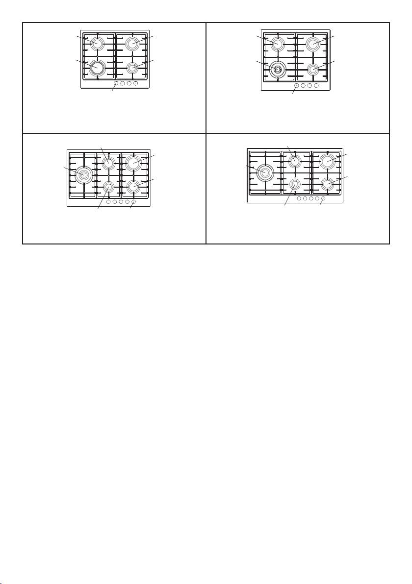
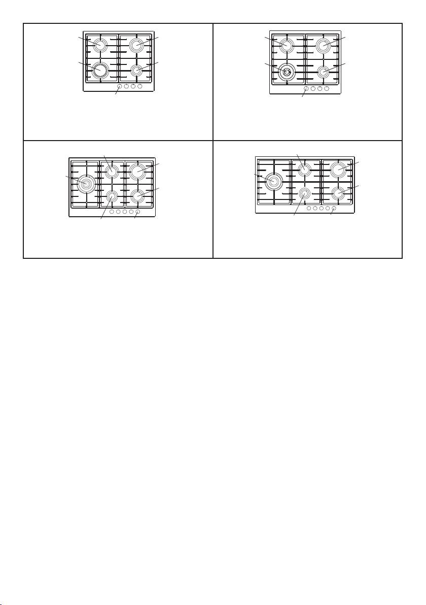
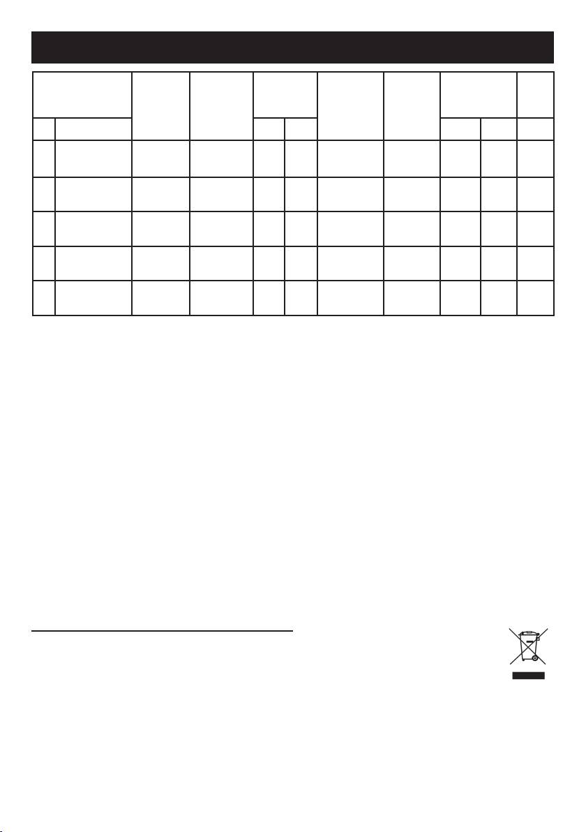
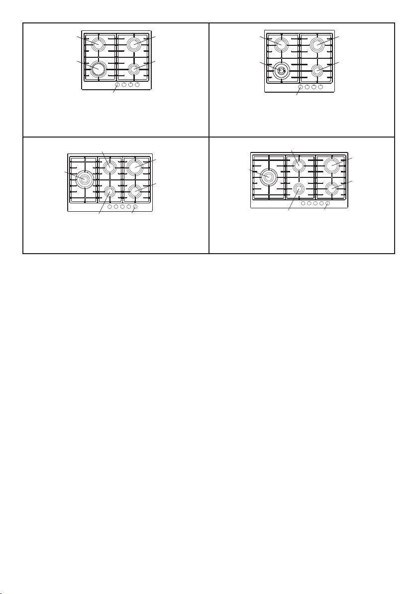
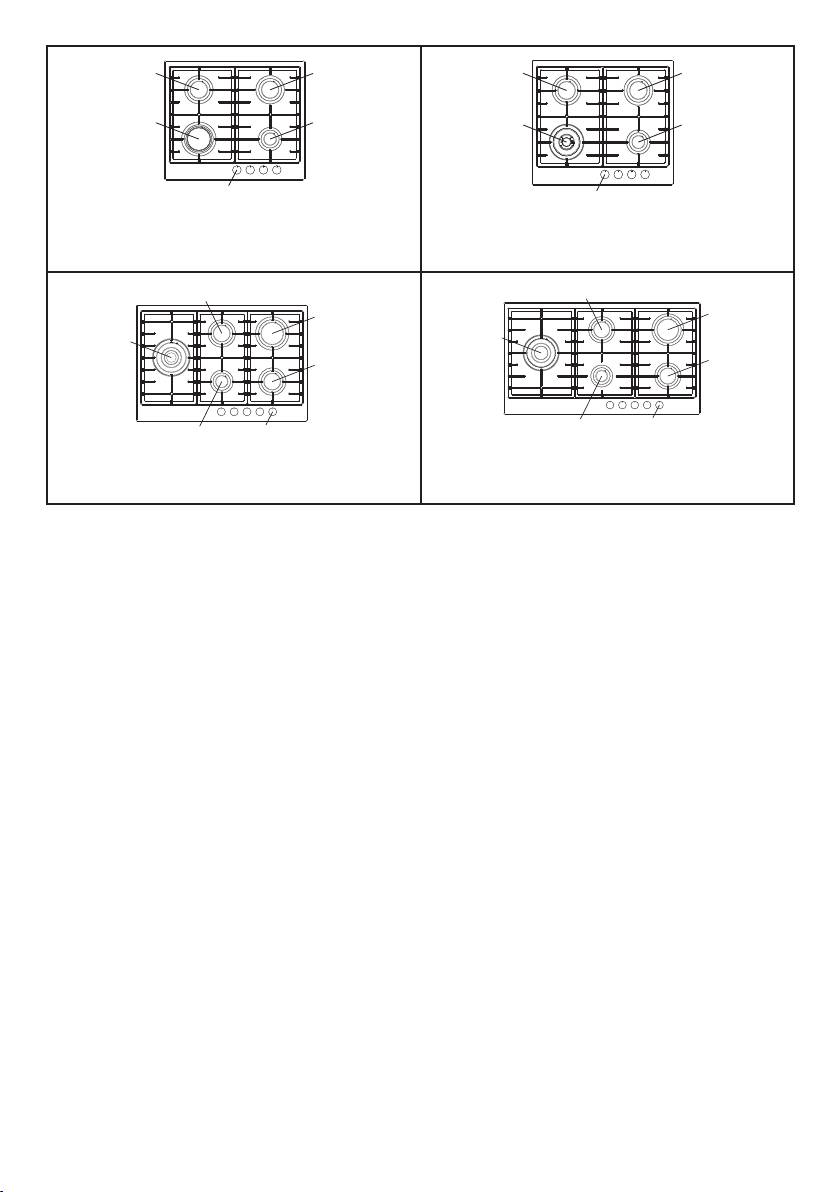
1 Bruciatore rapido di 3000 W
2 Bruciatore semirapido di 1750 W
3 Bruciatore ausiliario di 1000 W
4 Bruciatore tripla corona di 3800 W
5 Bruciatore doppia corona di 3500 W
8 Manopola comando bruciatore
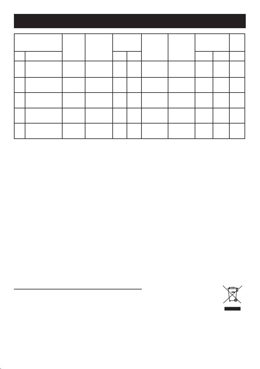
TABELLA CARATTERISTICHE TECNICHE
DIAMETRO
(EE
PRESSIONE
PORTATA
DIAMETRO
PORTATA
BRUCIATORI
BY PASS
gas
ESERCIZIO
TERMICA
UGELLO
TERMICA (W)
GAS
RUBINETTO
)
hob
N° DENOMINAZIONE mbar g/h L/h 1/100 mm 1/100 mm Max. Min. (%) *
G30 - G31 28 - 30 225 - 85 42 3000 950
1 RAPIDO
56.7
G20 20 - 290 115Y Reg. 3000 950
G30 - G31 28 - 30 126 - 65 31 1750 600
2 SEMIRAPIDO
57
G20 20 - 165 97Z Reg. 1750 600
G30 - G31 28 - 30 71 - 50 27 1000 450
3 AUSILIARIO
/
G20 20 - 99 72X Reg. 1000 450
G30 - G31 28 - 30 278 - 98 60 3800 2100
TRIPLA CORONA
4
58.1
SABAF
G20 20 - 367 135K Reg. 3800 2100
G30 - G31 28 - 30 255 - 93 60 3500 2100
DOPPIA CORONA
5
56.6
DEFENDI
G20 20 - 334 135 Reg. 3500 2100
Titolo breve o riferimento ai metodi di misurazione e di calcolo utilizzati per stabilire la conformità
con i requisiti di cui sopra.
La performance di ogni singolo bruciatore viene calcolata secondo la norma EN 30-2-1 + A1: 2003 + A2:
2005.
Il rendimento totale del piano di cottura è calcolato in base al regolamento UE 66/2014 Par. 2.2.
L’efcienza viene calcolata solo per i bruciatori con una capacità nominale superiore 1,16 KW (EN 30-2-1
+ A1: 2003 + A2:. 2005; Par 4.1)
Informazioni rilevanti per il cliente per minimizzare il consumo di energia durante l’uso.
Consigli per risparmiare:
utilizzare pentole comuni con base piana,
utilizzare pentole con il formato corretto,
utilizzare pentole con il coperchio,
ridurre al minimo la quantità di grasso liquido o, quando si avvia un liquido bollente ridurre l’impostazione.
Questo prodotto è conforme alla Direttiva EU 2002/96/EC.
Il simbolo del cestino barrato riportato sul prodotto indica che i Riuti derivanti dalle Apparecchiature
Elettriche ed Elettroniche (RAEE) non devono essere buttati nella spazzatura indifferenziata (cioè insieme
ai “riuti urbani misti”), ma devono essere gestiti separatamente così da essere sottoposti ad apposite
operazioni per il loro riutilizzo, oppure a uno specico trattamento, per rimuovere e smaltire in modo
sicuro le eventuali sostanze dannose per l’ambiente ed estrarre le materie prime che possono essere riciclate.
In Italia i RAEE devono perciò essere consegnati ai Centri di Raccolta (chiamati anche isole ecologiche o piattaforme
ecologiche) allestiti dai Comuni o dalle Società di igiene urbana. Quando si acquista una nuova apparecchiatura, inoltre,
si può consegnare il RAEE al negoziante, che è tenuto a ritirarlo gratuitamente (ritiro “uno contro uno”); i RAEE di
“piccolissime dimensioni” (nei quali cioè nessuna dimensione supera i 25 cm) possono essere consegnati gratuitamente
ai negozianti anche quando non si compra nulla (ritiro “uno contro zero” – che però è obbligatorio solo per i negozi con
supercie di vendita superiore a 400 mq).
4

ISTRUZIONI PER L’UTENTE
È necessario che tutte le operazioni relative all’installazione, alla regolazione,
all’adattamento al tipo gas disponibile, vengano eseguite da personale qualificato,
secondo le norme in vigore.
Le istruzioni specifiche sono descritte nella parte del libretto riservate
all’installatore.
USO DEI BRUCIATORI
- Per ripristinare il funzionamento riportare la
La simbologia serigrafata a lato delle manopole,
manopola al punto di accensione (fiamma grande
indica la corrispondenza tra manopola e bruciatore.
fig. 1) e premere.
- Durante la cottura con grassi o olii, porre
Accensione automatica senza valvolatura
la massima attenzione in quanto gli stessi,
Ruotare in senso antiorario la manopola
surriscaldandosi, possono infiammarsi.
corrispondente fino alla posizione di massimo
- Non utilizzare spray vicino all’apparecchio in
(fiamma grande fig.1) e premere la manopola.
funzione.
Accensione automatica con valvolatura
- Non devono essere poste sul bruciatore pentole
Ruotare in senso antiorario la manopola
instabili o deformate per evitare incidenti di
corrispondente fino alla posizione di massimo
rovesciamento o trabocco.
(fiamma grande fig.1) e premere la manopola.
- Assicurarsi che le maniglie delle pentole siano
Ad accensione avvenuta mantenere premuta la
posizionate correttamente.
manopola per circa 6 secondi.
- Quando si accende il bruciatore controllare che la
ATTENZIONE: l’accensione del bruciatore tripla
fiamma sia regolare, abbassare sempre la fiamma
corona puo’ avvenire solo nella posizione di
massimo.
o spegnerla prima di togliere le pentole.
Uso dei bruciatori
PULIZIA
Per ottenere il massimo della resa senza spreco di
Prima di ogni operazione scollegare l’apparec-
gas è importante che il diametro della pentola sia
chio dalla rete di alimentazione elettrica.
adeguato alla potenzialità del bruciatore (vedi tabella
Non utilizzare pulitori a vapore per la pulizia
seguente), in modo da evitare che la fiamma esca
dell’apparecchio.
dal fondo della pentola (fig.2).
Si consiglia di operare ad apparecchio freddo.
Utilizzare la portata massima per portare
Parti smaltate
rapidamente in ebollizzione i liquidi e quella ridotta
Le parti smaltate devono essere lavate con una
per riscaldare le vivande o per il mantenimento
spugna ed acqua saponata o con detersivo leggero.
dell’ebollizione.
Non usare prodotti abrasivi o corrosivi.
Tutte le posizioni di funzionamento devono essere
Evitate che sostanze come succo di limone,
scelte tra quelle di massimo e quella di minimo, mai
pomodoro, acqua salina, aceto, caffè e latte
tra la posizione di massimo e il punto di chiusura.
rimangano a lungo sulle superfici smaltate.
Per interrompere l’alimentazione gas, ruotare la
Parti in acciaio inox
manopola in senso orario sulla posizione di chiusura.
L’acciaio inox può rimanere macchiato se lasciato
In mancanza di energia elettrica è possibile
a contatto per lungo tempo con acqua calcarea o
accendere i bruciatori con i fiammiferi posizionando
detergenti aggressivi.
la manopola al punto di accensione (fiamma grande
Si consiglia di lavare con acqua saponata e
fig. 1).
asciugare con panno morbido.
La lucentezza viene mantenuta mediante l’uso
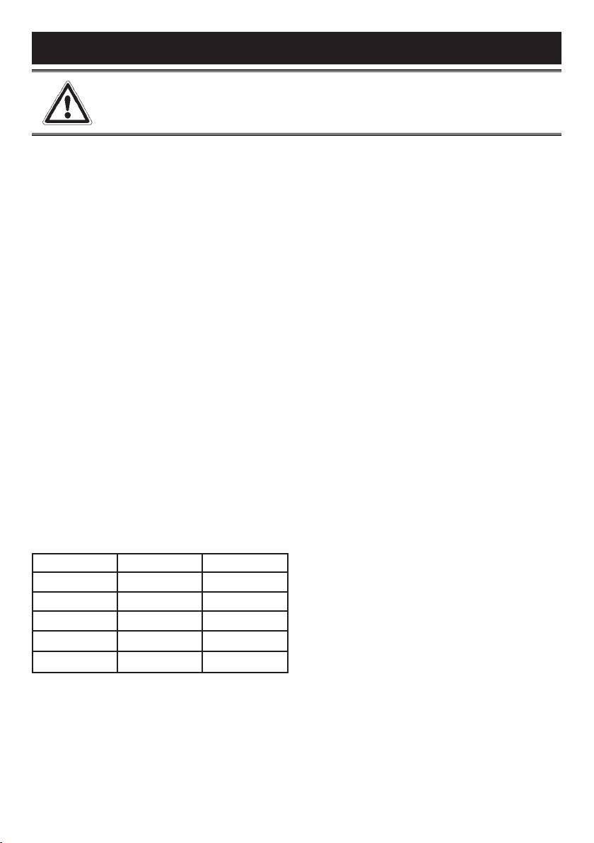
Bruciatori Potenze (W) Ø Pentole
periodico di prodotti chimici idonei, reperibili in
commercio.
Ausiliario 1000 10 - 14 cm
Bruciatori e griglie
Semirapido 1750 16 - 18 cm
Questi pezzi possono essere tolti per facilitare la
pulizia.
Rapido 3000 20 - 22 cm
I bruciatori devono essere lavati con una spugna
ed acqua saponata o con detersivo leggero,
Tripla Corona 3800 22 - 24 cm
ben asciugati e rimessi perfettamente nel loro
Doppia Corona 3500 18 - 20 cm
alloggiamento.
Controllare che i canali spartifiamma non siano
ostruiti.
Avvertenze
Verificare che la sonda della valvola di sicurezza e
- Controllare sempre che le manopole siano
l’elettrodo di accensione siano sempre ben puliti per
nella posizione di chiuso (vedi fig.1) quando
garantire un funzionamento ottimale.
l’apparecchiatura non è in funzione.
- In caso di spegnimento accidentale della fiamma,
Rubinetti a gas
la valvola di sicurezza, dopo qualche secondo,
L’eventuale lubrificazione dei rubinetti deve essere
interromperà automaticamente l’erogazione del
eseguita esclusivamente da personale specializzato.
gas.
In caso di indurimento o di anomalie di
funzionamento dei rubinetti gas chiamare il
Servizio di Assistenza.
5
ISTRUZIONI PER L’INSTALLATORE
AVVERTENZA IMPORTANTE:
LE OPERAZIONI DI SEGUITO RIPORTATE DEVONO ESSERE ESEGUITE, NEL RISPETTO DELLE
NORME VIGENTI, ESCLUSIVAMENTE DA PERSONALE QUALIFICATO.
LA DITTA COSTRUTTRICE DECLINA OGNI RESPONSABILITÀ PER DANNI A PERSONE ANIMALI O
COSE DERIVANTI DALL’INNOSSERVANZA DI TALI DISPOSIZIONI.
INSTALLAZIONE
speciale guarnizione.
Viene inoltre fornita una serie di ganci da utilizzare
Montaggio del piano
per il fissaggio del piano. A seconda del tipo di
L’apparecchio è costruito per essere incassato in
fondo, viene fornito il tipo di gancio di fissaggio
mobili resistenti al calore.
adatto (gancio A o gancio B). Per l’installazione
Le pareti dei mobili devono resistere ad una
procedere come segue:
temperatura di 75°C oltre a quella ambientale
- Togliere dal piano griglie e bruciatori.
secondo le normative europee.
- Rovesciare l’apparecchio e stendere lungo il
L’apparecchio è di tipo “Y“, ovvero può essere
bordo esterno la guarnizione S (fig. 5).
installato con una sola parete laterale a destra o a
- Inserire e posizionare il piano cottura nell’apertura
sinistra del piano cottura.
praticata nel mobile e bloccarlo con le viti V dei
Evitare l’installazione dell’apparecchiatura in
ganci di fissaggio G (fig. 6 / 6A).
prossimità di materiali infiammabili come tendaggi,
canevacci, ecc.
Locale di installazione
Praticare un’apertura nel piano del mobile delle
Questo apparecchio non è provvisto di
dimensioni indicate nella fig. 3 rispettando
un dispositivo di scarico dei prodotti della
una distanza di almeno 50 mm dal bordo
combustione, è necessario quindi scaricare
dell’apparecchio alle pareti adiacenti.
questi fumi all’esterno utilizzando una cappa o un
elettroventilatore che entri in funzione ogni volta
MODELLO L (mm) P (mm)
che si utilizza l’apparecchio.
600 - 750 560 480
Il locale dove viene installato l’apparecchio deve
avere un naturale afflusso d’aria per la regolare
900 805 480
combustione del gas e per la ventilazione del
locale; il volume d’aria necessario non deve essere
L’eventuale presenza di un pensile al di sopra del
3
inferiore a 20 m
.
piano cottura deve prevedere una distanza minima
L’afflusso dell’aria deve avvenire da aperture
dal top di 760 mm.
permanenti praticate sulle pareti del locale
Si consiglia di isolare l’apparecchio dal mobile
comunicanti con l’esterno.
sottostante con un separatore lasciando uno
La ventilazione può provvenire anche da un locale
spazio di depressione di almeno 10 mm. (fig. 4).
attiguo, in questo caso attenersi a quanto prescritto
Nel caso di inserimento su base con forno è
dalle norme in vigore.
necessario prendere opportune precauzioni al
Le aperture dovranno avere una sezione minima di
fine di assicurare un’installazione conforme alle
2
200 cm
.
norme antinfortunistiche. Si presti particolare
attenzione a che il cavo elettrico ed il tubo di
Collegamento gas
alimentazione siano posizionati in modo da non
Accertarsi che l’apparecchio sia predisposto
venire a contatto con le parti calde dell’involucro
al tipo di gas disponibile, vedi l’etichetta sotto
del forno. Inoltre, nel caso di installazione sopra un
l’apparecchio. Operare secondo le istruzioni
forno senza ventilazione forzata di raffreddamento,
riportate al paragrafo “trasformazioni gas e
per consentire un’adeguata aerazione dovranno
regolazioni“ per l’eventuale adattamento a gas
essere previste delle opportune prese d’aria con
2
diversi.
superficie di entrata inferiore di almeno 200 cm
e
2
L’apparecchio deve essere collegato all’impianto
superficie di uscita superiore di almeno 60 cm
.
gas utilizzando tubi metallici rigidi conformi alla
Fissaggio del piano
norma in vigore o con tubi flessibili in acciaio a
Ogni piano di cottura viene corredato di una
parete continua conformi alla norma in vigore.
6
ISTRUZIONI PER L’INSTALLATORE
Alcuni modelli hanno in dotazione due raccordi:
fatta secondo la tabella “caratteristiche tecniche”
uno cilindrico A, uno conico B (fig. 7). Scegliere
riportata di seguito.
il raccordo appropriato in base al paese
Procedere quindi come segue:
d’installazione.
- Togliere le griglie e i bruciatori.
Il collegamento non deve provocare sollecitazioni
- Con una chiave diritta L svitare l’ugello U (fig. 8)
lla rampa gas.
e sostituirlo con quello corrispondente.
Ad installazione ultimata controllare la tenuta
- Bloccare energicamente l’ugello.
dei collegamenti con una soluzione saponosa.
Regolazione bruciatori
Collegamento elettrico
La regolazione del minimo deve essere sempre
L’allacciamento alla rete elettrica deve essere
corretta e la fiamma deve rimanere accesa anche
eseguito da personale qualificato e secondo le
con un brusco passaggio dalla posizione di
norme vigenti.
massimo a quella di minimo.
La tensione dell’impianto elettrico deve
Se questo non avviene è necessario regolare il
corrispondere a quelle indicata sulla etichetta sotto
minimo come segue:
l’apparecchio.
- Accendere il bruciatore;
Verificare che l’impianto elettrico sia munito di un
- Ruotare il rubinetto fino alla posizione di minimo
efficace collegamento di terra secondo le norme
(fiamma piccola);
e le disposizioni di legge. La messa a terra è
- Sfilare la manopola dall’asta del rubinetto;
obbligatoria.
- Introdurre un cacciavite a taglio nel foro F del
Se l’apparecchio è sprovvisto di spina, applicare al
rubinetto (fig. 9-9/A) e ruotare la vite by-pass fino
cavo di alimentazione una spina normalizzata.
ad una corretta regolazione del minimo.
Per il collegamento diretto alla rete, è
Per bruciatori funzionanti a gas G30 la vite by-
necessario prevedere un dispositivo che
pass deve essere avvitata completamente.
assicuri la disconnessione dalla rete, con una
distanza di apertura dei contatti che consenta la
MANUTENZIONE
disconnessione completa nelle condizioni della
categoria di sovratensione III, conformemente alle
Sostituzione cavo alimentazione
regole di installazione.
In caso di sostituzione del cavo di alimentazione si
dovrà utilizzare un cavo a norme del tipo H05VV-F
TRASFORMAZIONI GAS E REGOLAZIONI
2
o H05RR-F di sezione 3 x 0,75 mm
.
Il collegamento alla morsettiera va eseguito come
Sostituzione ugelli
illustrato in fig. 10 e 10/A:
Se l’apparecchiatura risulta predisposta per
cavetto L marrone (fase)
un diverso tipo di gas di quello disponibile è
cavetto N blu (neutro)
necessario sostituire gli ugelli dei bruciatori.
cavetto verde-giallo (terra)
La scelta degli ugelli da sostituire deve essere
La casa costruttrice declina ogni responsabilità per possibili inesattezze, imputabili ad errori di stampa o di
trascrizione, contenute nel presente libretto. Si riserva il diritto di apportare ai propri prodotti tutte le modifiche
che riterrà opportune, senza pregiudicare le caratteristiche essenziali di funzionalità e di sicurezza.
7
CENTRI ASSISTENZA TECNICA
Per Assistenza Tecnica Autorizzata e Ricambi Originali rivolgersi al numero unico*
Numero unico
848 99 87 03
Oppure visitare il sito www.bompani.it
* al costo massimo di 2 centesimi di euro al minuto (iva inclusa) anche da cellulare.
CONDIZIONI DI GARANZIA
Le Condizioni di Garanzia sono consultabili sul nostro sito www.bompani.it
8
GB
GENERAL NOTICE
We invite you to read this instruction booklet carefully, before installing and using the equipment.
It is very important that you keep this booklet together with the equipment for any future
consultation.
If this equipment should be sold or transferred to another person, make sure that the new
user receives the booklet, so that he can learn how to operate the appliance and read the
corresponding notice.
This is a Class 3 appliance.
This appliance complies with the following Directives:
EEC 2009/142/CE (Gas) EEC 2004/108/CE (Electromagnetic Compatibility)
EEC 2006/95/CE (Low Voltage) EEC 2004/1935/CE (Contact with foods)
- The installation must be carried out by experienced and qualified personnel, in conformity with the
regulations in force.
- This appliance is not intended for use by person (including children) with reduced physical, sensory or
mental capabilities, or lack of experience and knowledge, unless they have been given supervision or
instruction cencerning use of the appliance by a person responsible for their safety.
- Children should be supervised to ensure that they do not play with the appliance.
- While the appliance is running, watch the children and make sure they neither stay near the equipment,
nor touch the surfaces that have not cooled down completely.
- Before powering the equipment, check that it is properly adjusted for the type of gas at disposal (see the
“installation” paragraph).
- Before carrying out the maintenance or cleaning the equipment, cut power supply off and make it cool
down.
- Make sure that air circulates around the gas equipment. Insufficient ventilation produces a lack of oxygen.
- In case of an intense or prolonged use of the equipment, it may be necessary to improve aeration, for
example by opening a window or increasing the mechanical suction power, if it exists.
- The products of combustion must be discharged outside through a suction hood or an electric fan (see the
“installation” paragraph).
- For any possible operation or modification, apply to an authorized Technical Assistance Centre and
demand original spare parts.
WARNING:
The product label, with the serial number, is sticked under the hob.
The manufacturer refuses all responsibility for possible damages to things or people, resulting
from a wrong installation or from an improper, incorrect or unreasonable use of this equipment.
9
1 Rapid burner 3000 W
2 Semi-rapid burner 1750 W
3 Auxiliary burner 1000 W
4 Triple ring burner 3800 W
5 Double ring burner 3500 W
8 Control knob for burner
10
2 2
1
3
8
2 2
5
3
8
(EE
= 56.9 %) (EE
= 56.9 %)
gas hob
gas hob
2
2
1
1
4
4
2
2
3
8
3
8
(EE
= 57.2 %) (EE
= 57.2 %)
gas hob
gas hob
TECHNICAL CHARACTERISTIC TABLES
TAPE BY
NORMAL
NORMAL
INJECTOR
NOMINAL HEAT
(EE
gas
BURNERS
PASS
PRESSURE
RATE
DIAMETER
INPUT (W)
)
hob
GAS
DIAMETER
N° DESCRIPTIONS mbar g/h L/h 1/100 mm 1/100 mm Max. Min. (%) *
G30 - G31 28 - 30 225 - 85 42 3000 950
1 RAPID
56.7
G20 20 - 290 115Y Reg. 3000 950
G30 - G31 28 - 30 126 - 65 31 1750 600
2 SEMI-RAPID
57
G20 20 - 165 97Z Reg. 1750 600
G30 - G31 28 - 30 71 - 50 27 1000 450
3 AUXILIARY
/
G20 20 - 99 72X Reg. 1000 450
G30 - G31 28 - 30 278 - 98 60 3800 2100
TRIPLE RING
4
58.1
SABAF
G20 20 - 367 135K Reg. 3800 2100
G30 - G31 28 - 30 255 - 93 60 3500 2100
DOUBLE RING
5
56.6
DEFENDI
G20 20 - 334 135 Reg. 3500 2100
Short title or reference to the measurement and calculation methods used to establish compli-
ance with the above requirements.
The performance of each individual burner is calculated according to standard EN 30-2-1 + A1:2003 +
A2:2005
The total efciency of the hob is calculated according to the EU Regulation 66/2014 Par. 2.2
The efciency is calculated only for the burners with a nominal capacity exceeding 1,16 KW ( EN 30-2-1
+ A1:2003 + A2:2005; Par. 4.1)
Information which is relevant to the customer to minimize the energy consumption during usage:
Energy Saving Tips: use pots having at base, Use pots with proper size, use pots with lid, minimize the
amount of liquid or fat, when liquid starts boiling reduce the setting.
This product complies with EU Directive 2002/96/EC.
The crossed-out dustbin symbol reported on the appliance indicates that the appliance must be
disposed of separately from other domestic refuse at the end of its useful life. It must therefore be
delivered to a waste recycling centre specifically for electric and electronic equipment or returned
to the retailer at the moment of purchase of a new equivalent appliance.
The user is responsible for delivering the appliance to the appropriate collection centre at the end of its useful
life, Failure to do so may result in a fine, as provided for by laws governing waste disposal. Differential collection
of waste products for eventual recycling, treatment and environmentally friendly disposal helps reduce possible
negative effects on the environment and health, and also enables the materials making up the product to be
recycled. For more detailed information on the available refuse collection systems, refer to the local Municipal
Solid Waste disposal centre or the shop where the product was purchased. Producers and importers are
responsible for fulfilling their obligations as regards recycling, treatment and environmentally friendly disposal by
directly or indirectly participating in the collection system.
11
INSTRUCTIONS FOR THE USER
It is necessary that all the operations regarding the installation, adjustment and
adaptation to the type of gas available are carried out by qualified personnel, in
conformity with the regulations in force.
The specific instructions are described in the booklet section intended for the
installer.
- Do not use sprays near the appliance in operation.
USING THE BURNERS
- Do not place unstable or deformed pots on the burner, so
The symbols silk-screen printed on the side of the knob
as to prevent them from overturning or overflowing.
indicate the correspondence between the knob and the
- Make sure that pot handles are placed properly.
burner.
- When the burner is started up, check that the flameis
regular and, before taking pots away, always lowerthe
Start-up without valves
flame or put it out.
Turn the corresponding knob anticlockwise up to the
maximum position (large flame, fig. 1) and press.
CLEANING
Automatic start-up with valves
Before any operation, disconnect the appliance from
Turn the corresponding knob anticlockwise up to the
the electric grid.
maximum position (large flame, fig. 1) and press the knob.
Don’t use a steam cleaner for the cleaning the hob.
Once the burner has been started up, keep the knob
It is advisable to clean the appliance when it is cold.
pressed for about 6 seconds.
ATTENTION: the triple ring burner switches on only in
Enamelled parts
the maximum flame position.
The enamelled parts must be washed with a sponge and
soapy water or with a light detergent.
Using the burners
Do not use abrasive or corrosive products.
In order to obtain the maximum yield without waste of
Do not leave substances, such as lemon or tomato juice,
gas, it is important that the diameter of the pot is suitable
salt water, vinegar, coffee and milk on the enamelled
for the burner potential (see the following table), so as to
surfaces for a long time.
avoid that the flame goes out of the pot bottom (fig. 2).
Use the maximum capacity to quickly make the liquids
Stainless steel parts
reach the boiling temperature, and the reduced capacity to
Stainless steel can be stained if it remains in contact with
heat food or maintain boiling. All of the operating positions
highly calcareous water or aggressive detergents for an
must be chosen between the maximum and the minimum
extended period of time.
ones, never between the minimum position and the
The stainless steel parts should also be cleaned with
closing point.
soapy water and then dried with a soft cloth.
The gas supply can be interrupted by turning the knob
clockwise up to the closing position.
Burners and racks
If there is no power supply, it is possible to light the
These parts can be removed to make cleaning easier.
burners with matches, setting the knob to the start-up
The burners must be washed with a sponge and soapy
point (large flame, fig. 1).
water or with a light detergent, wiped well and placed in
their housing perfectly. Make sure that the ame-dividing
BURNERS POWER W Ø of pots
ducts are not clogged.
Check that the feeler of the safety valve and the start-up
Auxiliary 1000 10 - 14 cm
electrode are always perfectly cleaned, so as to ensure an
Semi-rapid 1750 16 - 18 cm
optimum operation.
Rapid 3000 20 - 22 cm
Gas taps
Triple crown 3800 22 - 24 cm
The possible lubrication of the taps must be carried out by
specialized personnel, exclusively.
Double crown 3500 18 - 20 cm
In case of hardening or malfunctions in the gas taps,
apply to the Customer Service.
Notice
- When the equipment is not working, always check that
the knobs are in the closing position (see fig.1).
- If the flame should blow out accidentally, the safety
valve will automatically stop the gas supply, after a few
seconds. To restore operation, set the knob to the lighting
point (large flame, fig. 1) and press.
- While cooking with fat or oil, pay the utmost attention as
these substances can catch fire when overheated.
12
INSTRUCTIONS FOR THE INSTALLER
IMPORTANT NOTICE:
THE OPERATIONS INDICATED BELOW MUST BE FOLLOWED BY QUALIFIED PERSONNEL
EXCLUSIVELY, IN CONFORMITY WITH THE REGULATIONS IN FORCE.
THE MANUFACTURING FIRM REFUSES ALL RESPONSIBILITY FOR DAMAGES TO PEOPLE,
ANIMALS OR THINGS, RESULTING FROM THE FAILURE TO COMPLY WITH SUCH PROVISIONS.
INSTALLATION
or hook B).
For the installation proceed as follows:
Installing the top
- Remove the racks and burners from the top.
The appliance is designed to be embedded into
- Turn the appliance upside down and lay the
heat-resistant pieces of furniture.
washer S along the external border (fig. 5).
The walls of the pieces of furniture must resist a
- Introduce and place the cook-top in the hole made
temperature of 75°C besides the room one.
in the piece of furniture, then block it with the V
The equipment must not be installed near
screws of the fastening hooks G (fig.6 / 6A).
inflammable materials, such as curtains, cloths,etc.
Make a hole in the top of the piece of furniture, with
Installation room
the dimensions indicated in fig. 3, at a distance of
This appliance is not provided with a device for
at least 50 mm from the appliance border to the
exhausting the products of combustion.
adjacent walls.
Regarding room ventilation rules where appliance
is installed make reference to the legislation, in
conformity with the local regulations.
MODEL L (mm) P (mm)
600 - 750 560 480
FOR THE U.K. ONLY
900 805 480
The room containing this hotplate should have an
air supply in accordance with BS 5440: Part 2:
Any possible wall unit over the cook-top must be
1989.
placed at a distance of at least 760 mm from the
top.
- All rooms require an openable window, or
It is advisable to isolate the appliance from the
equivalent and some rooms will require a
piece of furniture below with a separator, leaving a
permanent vent a well.
depression space of at least 10 mm (fig. 4).
3
2
- For room volumes up to 5 m
an air vent of 100cm
If the hob is going to be installed on the top of an
is required.
oven, precautions must be taken to guarantee an
3
3
- For room volumes between 5 m
and 10 m
an air
installation in accordance with current accident
2
vent of 50 cm
is required.
prevention standards. Pay particular attention to
3
- If the room is greater than 5 m
and has a door
the position of the electric cable and gas pipe: they
that opens directly to the outside, then no air vent
must not touch any hot parts of the oven.
is required.
Moreover, if the hob is going to be installed on
the top of a built in oven without forced cooling
If there are other fuel burning appliances in the
ventilation, proper air vents must be installed to
same room BS 5440: Part 2:1989 should be
guarantee an adequate ventilation, with the lower
consulted to determine the air vent requirements.
2
air entering with a cross section of at least 200cm
,
Gas connection
and the higher air exiting with a cross section of at
Make sure that the appliance is adjusted for
2
least 60 cm
.
the gas type available (see the label under the
appliance). Follow the instructions indicated in the
Fastening the top
chapter “gas transformations and adjustments” for
Every cook-top is equipped with a special washer.
the possible adaptation to different gases.
A set of hooks is also supplied for mounting the
The appliance must be connected to the gas
cook-top.
system by means of stiff metal pipes or flexible
Depending on the type of mounting surface, the
steel pipes having continuous walls, in compliance
suitable type of mounting hook is supplied (hook A
with the regulations in force.
13
INSTRUCTIONS FOR THE INSTALLER
Some models are equipped with both cylindrical A
Adjusting the burners
and conical B connectors for gas supply (fig. 7).
The lowest flame point must always be properly
Please select the type which is correct for the
adjusted and the flame must remain on even if
supply concerned.
there is an abrupt shift from the maximum to the
The connection must not stress the gas ramp.
minimum position.
Once the installation is over, check the
If this is not so, it is necessary to adjust the lowest
connection seal with a soapy solution.
flame point as follows:
- start the burner up
Electric connection
- turn the tap up to the minimum position (small
The connection to the electric grid must be carried
flame)
out by qualified personnel and in conformity with
- remove the knob from the tap rod
the regulations in force.
- introduce a flat-tip screwdriver in the hole F of the
The voltage of the electric system must correspond
tap (fig. 9-9/A) and turn the by-pass screw up to a
to the value indicated in the label under the
proper adjustment of the lowest flame point.
appliance. Make sure that the electric system is
provided with an effective ground connction in
As regards G30 gas burners, the by-pass screw
compliance with the regulations and provisions of
must be tightened completely.
the law. Grounding is compulsory.
MAINTENANCE
GAS TRANSFORMATIONS AND ADJUSTMENTS
Replacing the power supply cable
Replacing the nozzles
If the power supply cable should be replaced,
If the equipment is adjusted for a type of gas that is
it is necessary to use a cable with a section of
different from the one available, it is necessary to
2
3x0.75mm
, type H05VV-F or H05RR-F, complying
replace the burner nozzles.
with the regulations in force.
The choice of the nozzles to replace must be
The connection to the terminal board must be
made according to the table of the “technical
effected as shown in fig. 10 - 10/A:
characteristics” as enclosed.
Act as follows:
brown cable L (phase)
- Remove the racks and burners.
blue cable N (neutral)
- By means of a straight spanner L, unscrew
green-yellow cable (ground)
the nozzle U (fig.8) and substitute it with the
corresponding one.
- Tighten the nozzle strongly.
The manufacturing firm refuses all responsibility for any possible imprecision in this booklet, due to misprints or
clerical errors. It reserves the right to make all the changes that it will consider necessary in its own products,
without effecting the essential characteristics of functionality and safety.
14

FR
AVERTISSEMENTS GENERAUX
Nous vous invitons à lire ce manuel d’instructions avant d’installer et d’utiliser l’appareil. Il est
très important que ce manuel soit conservé avec l’appareil afin de pouvoir être consulté en
cas de besoin. Si l’appareil est vendu ou donné à une autre personne, il faut s’assurer que ce
manuel est donné en même temps, de façon à ce que le nouvel utilisateur soit informé sur son
fonctionnement et prenne connaissance des avertissements correspondants.
Cet appareil appartient à classe 3
Appareil conforme aux directives:
EEC 2009/142/CE (Gaz) EEC 2004/108/CE (Compatibilité électromagnétique)
ECC 2006/95/CE (Basse tension) EEC 2004/1935/CE (Contact avec aliments)
- L’installation doit être effectuée par du personnel compétent et qualifié conformément aux normes en
vigueur.
- Cet appareil n’est pas prévu pour être utilisé par des personnes (y compris les enfants) dont les capacités
physiques, sensorielles ou mentales sont réduites, ou des personnes dénuées d’expérience ou de
connaissance, sauf si elles ont pu bénéficier, par l’intermédiaire d’une personne responsable de leur
sécurité, d’une surveillance ou d’instructions préalables concernant l’utilisation de l’appareil.
- Surveiller les enfants pendant le fonctionnement de l’appareil et veiller à ce qu’ils ne restent pas à
proximité et qu’ils ne touchent pas les surfaces qui n’ont pas encore complètement refroid.
- Avant d’alimenter l’appareil, contrôler qu’il est correctement réglé pour le type de gaz à disposition (voir
paragraphe “Installation”).
- Avant l’entretien et le nettoyage, débrancher électriquement l’appareil et le laisser refroidir.
- S’assurer qu’il y a une circulation d’air autour de l’appareil au gaz. Une faible ventilation entraîne une
carence d’oxygène.
- Si l’appareil est utilisé de manière intense ou prolongée, il peut être nécessaire de prévoir une aération
supplémentaire, en ouvrant par exemple une fenêtre ou en augmentant la puissance de l’aspiration
mécanique si celle-ci existe.
- Les produits de la combustion doivent être évacués à l’extérieur avec une hotte aspirante ou un ventilateur
électrique (voir paragraphe “Installation”).
- Pour les éventuelles interventions ou modifications, s’adresser à un Centre d’Assistance Technique agréé
et exiger des pièces de rechange originales.
ATTENTION:
L’étiquette produit, avec le numéro de série, est placée sous la table de cuisson.
Le fabricant décline toute responsabilité en cas de dommages aux choses ou aux personnes
dûs à une installation incorrecte ou à une utilisation inadéquate, erronée ou non raisonnable de
l’appareil.
15
1 Brûleur rapide de 3000 W
2 Brûleur semi-rapide de 1750 W
3 Brûleur auxiliaire de 1000 W
4 Brûleur triple couronne de 3800 W
5 Brûleur double couronne de 3500 W
8 Bouton commande brûleur
16
2 2
1
3
8
2 2
5
3
8
(EE
= 56.9 %) (EE
= 56.9 %)
gas hob
gas hob
2
2
1
1
4
4
2
2
3
8
3
8
(EE
= 57.2 %) (EE
= 57.2 %)
gas hob
gas hob
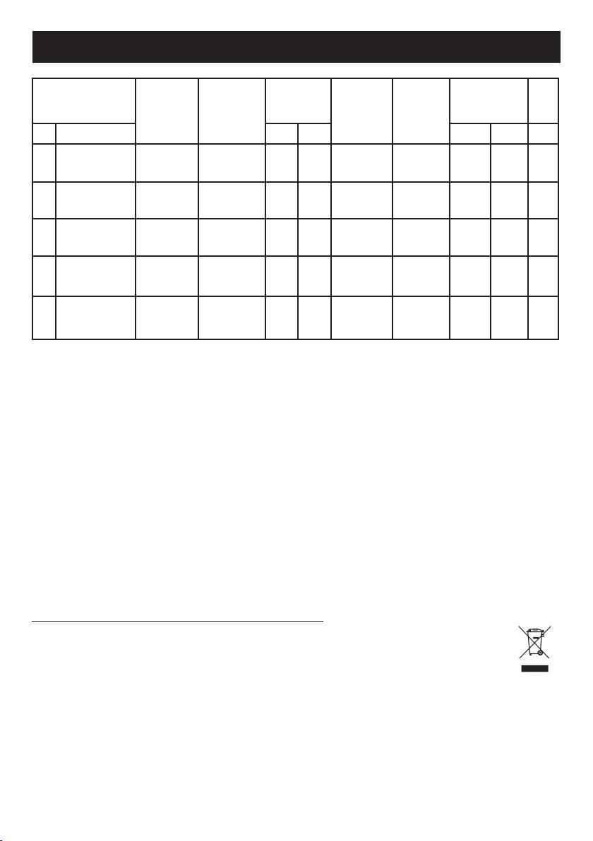
TABLE DE CARATERISTIQUES TECHNIQUES
PRESSION
DIAMÈTER
DEBIT
(EE
DIAMÈTER
BRÛLEUR
DE
DEBIT
BY PASS
CALORIFIQUES
gas
INJECTOR
GAZ
SERVICE
ROBINET
(W)
)
hob
N° DESIGNATION mbar g/h L/h 1/100 mm 1/100 mm Max. Min. (%) *
G30 - G31 28 - 30 225 - 85 42 3000 950
1 RAPIDE
56.7
G20 20 - 290 115Y Reg. 3000 950
G30 - G31 28 - 30 126 - 65 31 1750 600
2 SEMI-RAPIDE
57
G20 20 - 165 97Z Reg. 1750 600
G30 - G31 28 - 30 71 - 50 27 1000 450
3 AUXILIAIRE
/
G20 20 - 99 72X Reg. 1000 450
TRIPLE
G30 - G31 28 - 30 278 - 98 60 3800 2100
4
COURONNE
58.1
SABAF
G20 20 - 367 135K Reg. 3800 2100
DOUBLE
G30 - G31 28 - 30 255 - 93 60 3500 2100
5
COURONNE
56.6
DEFENDI
G20 20 - 334 135 Reg. 3500 2100
Titre abrégé ou références aux méthodes de mesure et de calcul utilisées pour établir la confor-
mité avec les exigences ci-dessus
La performance de chaque brûleur individuel est calculé selon la norme EN 30-2-1 + A1: 2003 + A2: 2005
Le rendement global de la table de cuisson est calculé selon le Règlement UE 66/2014 Par. 2.2
L'efcacité est calculée uniquement pour les brûleurs avec une capacité nominale est supérieure 1,16
KW (EN 30-2-1 + A1: 2003 + A2:. 2005; Par 4.1)
Information qui est pertinente pour le client an de minimiser la consommation d'énergie lors de
l'utilisation
L'économie d'énergie: utilisation des pots ayant fond plat, Utilisez des ustensiles avec la taille, de l'utilisa-
tion des pots avec couvercle, de minimiser la quantité de graisse liquide ou, lorsque le liquide commence
ébullition réduire le réglage.
Ce produit est conforme à la Directive EU 2002/96/EC.
Le logo « poubelle barrée » figurant sur l’appareil indique qu’au terme de son cycle de vie,
cet appareil doit être, non seulement traité séparément des déchets domestiques, mais aussi
remis à un centre de récupération pour équipements électriques et électroniques ou bien au
revendeur lors de l’achat d’un appareil neuf équivalent.
Une fois l’appareil au terme de son cycle de vie, l’utilisateur est tenu de le remettre aux structures de
récupération prévues à cet effet, sous peine des sanctions prévues par la législation en vigueur en
matière de déchets. Une collecte sélective adéquate permettant d’envoyer l’équipement éliminé au
recyclage, au traitement et à l’élimination compatible sur le plan environnemental contribue à éviter de
possibles effets négatifs sur l’environnement et la santé et facilite le recyclage des matériaux dont le
produit est constitué. Pour plus de détails quant aux systèmes de récupération disponibles, s’adresser
au service local chargé de l’élimination des déchets ou au magasin où l’équipement a été acheté. Les
producteurs et les importateurs respecteront leurs obligations en vue du recyclage, du traitement et
de l’élimination compatible sur le plan environnemental aussi bien directement qu’en participant à un
système collectif.
17
INSTRUCTIONS POUR L’UTILISATEUR
Toutes les opérations relatives à l’installation, au réglage et à l’adaptation au type
de gaz disponible doivent être effectuées par du personnel qualifié, conformément
aux normes en vigueur. Les instructions spécifiques sont reportées dans la partie
du manuel réservée à l’installateur.
surchauffées, peuvent s’enflammer.
UTILISATION DES BRULEURS
Le symbole appliqué par sérigraphie à côté du bouton
- Ne pas utiliser de vaporisateurs près de l’appareil en
indique à quel brûleur celui-ci correspond.
fonction.
- Il ne faut pas poser sur les brûleurs des casseroles
Allumage automatique sans soupape de sécurité
instables ou déformées afin d’éviter des accidents de
Tourner dans le sens inverse des aiguilles d’une montre
renversement ou de débordement.
le bouton correspondant jusqu’à la position de maximum
- S’assurer que les poignées des casseroles soient
(grande flamme, fig. 1) et appuyer sur le bouton.
positionnées correctement.
Allumage automatique avec soupape de sécurité
- Quand on allume le brûleur, contrôler que la flamme est
Tourner dans le sens inverse des aiguilles d’une montre
régulière; abaisser toujours la flamme ou l’éteindre avant
le bouton correspondant jusqu’à la position de maximum
d’enlever la casserole.
(grande flamme, fig. 1) et appuyer sur le bouton.
Une fois l’allumage obtenu, maintenir le bouton appuyé
NETTOYAGE
pendant environ 10 secondes.
Avant toute opération de nettoyage, débrancher
Attention: l’allumage du brûleur triple couronne ne
l’appareil du réseau d’alimentation électrique.
peut s’opérer que lorsque vous êtes en position
N’utilisez jamais d’appareils à vapeur ou à haute
maximale.
pression pour nettoyer le four (exigences relatives à
Utilisation des brûleurs
la sécurité électrique).
Pour obtenir un rendement optimal sans gaspillage de
Il est conseillé d’opérer quand l’appareil est froid.
gaz, il est important que le diamètre de la casserole soit
adapté au potentiel du brûleur (voir tableau ciaprès), de
Parties émaillées
façon à éviter que la flamme sorte du fond de la casserole
Les parties émaillées doivent être nettoyés avec une
(fig. 2).
éponge et de l’eau savonneuse ou avec un détergent
Utiliser le débit maximal pour amener rapidement à
léger.
ébullition les liquides et le débit réduit pour réchauffer les
Ne pas utiliser de produits abrasifs ou corrosifs.
aliments ou pour maintenir l’ébullition.
Eviter que les substances comme le jus de citron, la
Toutes les positions de fonctionnement doivent être
tomate, l’eau salée, le vinaigre, le café et le lait restent
choisies entre celles de maximum et de minimum et
pendant longtemps sur les surfaces émaillées.
jamais entre celle de maximum et le point de fermeture.
Pour interrompre l’alimentation en gaz, tourner le bouton
Parties en acier inoxydable
dans le sens des aiguilles d’une montre jusqu’à la position
Des taches peuvent se former sur l’acier inox s’il reste
de fermeture.
longtemps en contact avec de l’eau calcaire ou des
En cas d’absence d’énergie électrique, il est possible
détergents agressifs.
d’allumer les brûleurs avec des allumettes en positionnant
Il est conseillé de laver avec de l’eau savonneuse et de
le bouton sur le point d’allumage (grande flamme, fig. 1).
sécher avec un chiffon doux.
Le brillant se garde en utilisant périodiquement des
produits chimiques spécifiques se trouvant dans le
Brûleurs Puissance (W) Ø Casseroles
commerce.
Auxiliaire
1000 10 - 14 cm
Brûleurs et grilles
Semi-rapide
1750 16 - 18 cm
Ces parties peuvent être enlevées pour faciliter le
nettoyage.
Rapide
3000 20 - 22 cm
Les brûleurs doivent être nettoyés avec une éponge et
de l’eau savonneuse ou avec un détergent léger, bien
Triple couronne
3800 22 - 24 cm
essuyés et remis parfaitement dans leur siège. Contrôler
Double couronne
que les canaux de répartition des flammes ne sont pas
3500 18 - 20 cm
bouchés.
Vérifier que la sonde de la soupape de sécurité et
Avertissements
l’électrode d’allumage sont toujours bien propres afin de
- Contrôler toujours que les boutons sont sur la position
garantir un fonctionnement optimal.
“fermé” (voir fig. 1) quand l’appareil ne fonctionne pas.
- Si la flamme s’éteint accidentellement, après
Robinets de gaz
quelques secondes, la soupape de sécurité interrompt
L’éventuel graissage des robinets doit être effectué
automatiquement l’arrivée du gaz. Pour rétablir le
exclusivement par du personnel spécialisé.
fonctionnement, reporter le bouton au point d’allumage
Si les robinets de gaz deviennent difficiles à tourner
(grande flamme, fig.1) et appuyer sur le bouton.
ou ont un fonctionnement anormal, appeler le Service
- Pendant la cuisson avec des graisses et des huiles,
d’Assistance.
faire particulièrement attention car celles-ci, si elles sont
18

INSTRUCTIONS POUR L’INSTALLATEUR
AVERTISSEMENT IMPORTANT
LES OPERATIONS REPORTEES CI-APRES DOIVENT ETRE EXECUTEES DANS LE RESPECT DES
NORMES EN VIGUEUR, EXCLUSIVEMENT PAR DU PERSONNEL QUALIFIE. LE FABRICANT DECLINE
TOUTE RESPONSABILITE POUR LES DOMMAGES AUX PERSONNES, ANIMAUX ET CHOSES DERIVANT
DU NON-RESPECT DE CES DISPOSITIONS.
INSTALLATION
- Enlever les grilles et les brûleurs de la table de
cuisson.
Montage de la table de cuisson
- Retourner l’appareil et appliquer le joint adhésif S le
L’appareil est fabriqué pour être encastré dans des
long du bord externe du verre (fig. 5).
meubles résistant à la chaleur.
- Insérer et positionner la table de cuisson dans
Les parois des meubles doivent résister à une
l’ouverture pratiquée dans le meuble et la bloquer
température de 75°C en plus de la température
avec les vis V des crochets de fixation G (fig. 6/6A).
ambiante, conformément aux normes européennes.
L’appareil est de type “Y”, c’est-à-dire qu’il peut être
Pièce d’installation
installé avec une seule paroi latérale, à droite ou à
Cet appareil n’est pas équipé d’un dispositif
gauche de la table de cuisson.
d’évacuation des produits de la combustion ; il est
Eviter d’installer l’appareil à proximité de matériaux
donc nécessaire d’évacuer les fumées vers l’extérieur
inflammables comme des rideaux, des torchons, etc..
en utilisant une hotte ou un ventilateur électrique
Pratiquer une ouverture, dans le plateau du meuble,
qui soit mis en marche à chaque fois que l’on utilise
des dimensions indiquées en fig.3, en respectant une
l’appareil.
distance d’au moins 50 mm entre le bord de l’appareil
La pièce où est installé l’appareil doit avoir un afflux
et les parois voisines.
d’air naturel pour la combustion régulière du gaz
et pour la ventilation de la pièce : le volume d’air
3
nécessaire ne doit pas être inférieur à 20 m
. L’afflux
MODÈLE
L (mm) P (mm)
d’air doit s’effectuer par une ouverture permanente
pratiquée sur les murs de la pièce et communicante
600 - 750 560 480
avec l’extérieur.
900 805 480
La ventilation peut également provenir d’une pièce
contiguë, dans ce cas respecter les normes en vigueur
En cas de présence d’une armoire murale au-dessus
à ce sujet.
de la table de cuisson, il faut prévoir une distance
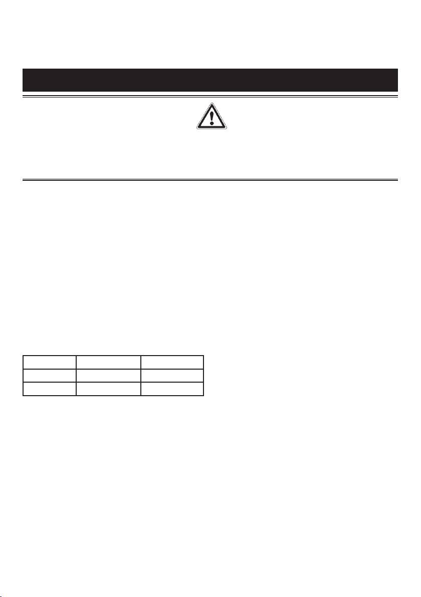
Les ouvertures doivent avoir une section minimale de
minimale de 760 mm entre celle-ci et le plan de travail.
2
200 cm
.
Il est conseillé d’isoler l’appareil du meuble se trouvant
Branchement gaz
audessous avec un séparateur en laissant un espace
S’assurer que l’appareil est adéquat pour le type de
de dépression d’au moins 10 mm (fig.4). En cas
gaz disponible; pour cela se référer à l’étiquette placée
d’encastrement sur une base avec four, il faudra
sous l’appareil ou à celle reportée sur la dernière page
s’assurer que l’installation réponde aux normes de
de ce manuel.
sécurité Il faudra en particulier veiller à ce que le câble
Opérer conformément aux instructions reportées au
électrique et le tuyau d’alimentation soient placés de
paragraphe “transformations gaz et réglages” pour
façon à ce qu’ils n’entrent pas en contact avec les
l’éventuelle adaptation à des gaz différents.
parties chaudes de l’enveloppe du four. De plus, en
L’appareil doit être raccordé à l’installation du gaz en
cas d’installation au-dessus d’un four encastré sans
utilisant des tubes métalliques rigides ou avec des
ventilation de refroidissement, il faudra prévoir, pour
tuyaux flexibles en acier à paroi continue conformes
obtenir une aération adéquate, des prises d’air avec
aux normes en vigueur.
2
entrée par le bas d’au moins 200 m
et sortie dans la
Certains modèles sont équipés de systèmes
2
partie supérieure d’au moins 6 cm
.
cylindriques A et coniques B pour le raccordement
au gaz (fig. 7). Sélectionnez le type adéquat pour un
Fixation de la table de cuisson
raccordement optimal.
Chaque table de cuisson est accompagnée d’un joint
Le raccordement ne doit pas provoquer de
spécial. De plus, une série de crochets à utiliser pour
sollicitations à la rampe de gaz.
la fixation de la table est également fournie. Le type
Une fois l’installation terminée, contrôler
de crochet de fixation (crochet A ou crochet B) est
l’étanchéité des raccordements avec une solution
fourni en fonction du type de fond. Pour l’installation,
savonneuse.
procéder de la façon suivante:
19
INSTRUCTIONS POUR L’INSTALLATEUR
Branchement électrique
Réglage des brûleurs
Le branchement au réseau électrique doit être exécuté
Le réglage du minimum doit toujours être correct et la
par du personnel qualifié conformément aux normes
flamme doit toujours rester allumée même en cas de
en vigueur.
passage rapide de la position de maximum à celle de
La tension de l’installation électrique doit correspondre
minimum.
à celle indiquée sur l’étiquette située sous l’appareil.
Si ce n’est pas le cas, il faut régler le minimum de
Vérifier que l’installation est équipée d’un branchement
la manière suivante:
à la terre efficace conformément aux normes et aux
- Allumer le brûleur;
dispositions de loi. La mise à la terre est obligatoire.
- Tourner le robinet jusqu’à la position de minimum
Si l’appareil est sans fiche, appliquer au câble
(petite flamme);
d’alimentation une fiche normalisée.
- Enlever le bouton de la tige du robinet;
Cet appareil doit être place à une distance raisonnable
- Introduire un tournevis à pointe plate dans le trou F du
afin de pouvoir être débranché en cas de survoltage
robinet (fig. 9-9/A) et tourner la vis by-pass jusqu’au
(catégorie III), en accord avec les règles d’installation.
réglage correct du minimum.
Pour les brûleurs fonctionnant au gaz G30, la vis
TRANSFORMATIONS GAZ ET REGLAGES
by-pass doit être complètement vissée.
Remplacement des buses
ENTRETIEN
Si l’appareil est prévu pour un type de gaz différent
de celui disponible, il faut remplacer les buses des
Remplacement câble d’alimentation
brûleurs.
En cas de remplacement du câble d’alimentation, il
Le choix des buses à remplacer doit être fait selon le
faut utiliser un câble conforme aux normes du type
2
tableau “caractéristiques techniques” annexé.
H05VV-F ou H05RR-F de section 3 x 0,75 mm
.
Procéder ensuite de la manière suivante:
Le branchement au bornier doit être effectué comme
- Enlever les grilles et les brûleurs.
indiqué en fig. 10 - 10/A:
- Avec une clé droite L, dévisser la buse U (fig. 8) et la
remplacer par la buse adéquate.
câble L marron (phase)
- Bloquer énergiquement la buse.
câble N bleu (neutre)
câble vert-jaune (terre)
Le fabricant décline toute responsabilité pour les éventuelles inexactitudes, imputables à des erreurs
d’impression ou de transcription, contenues dans ce manuel. Il se réserve le droit d’apporter à ses produits toutes
les modifications qu’il estimera opportunes, sans nuire aux caractéristiques essentielles de fonctionnement et de
sécurité.
20
RU
ОБЩИЕ РЕКОМЕНДАЦИИ ПО ИСПОЛЬЗОВАНИЮ
Перед тем как устанавливать прибор и начать им пользоваться, просим Вас внимательно
прочитать инструкцию по использованию. Очень важно, чтобы инструкция хранилась
вместе с прибором, чтобы к ней можно было обращаться в будущем в случае возникновения
каких-либо вопросов. В случае продажи или передачи прибора другому лицу проверьте,
чтобы ему также была передана и инструкция. Таким образом новый пользователь
сможет ознакомиться с правилами пользования и с инструкцией по безопасности. Данный
прибор относится к 3-му классу и должен использоваться только в целях, для которых он
предназначен, то есть для приготовления пищи в домашних условиях.
Этот прибор соответствует Директивам Европейского Союза:
ЕЕС 2009/142/CE (газ)
ЕЕС 2006/95/CE (приборы с низким напряжением)
ЕЕС 2004/108/CE (электромагнитная совместимость)
ЕЕС 2004/1935/CE (контакт с продуктами питания)
- Установка и обслуживание должны осуществляться только квалифицированными специалистами,
знающими действующие нормы установки электрических приборов.
- Данный прибор предназначен для использования совершеннолетними людьми.
- Храните эту инструкцию вместе с прибором
- Не разрешайте детям пользоваться прибором или играть поблизости от него.
- Следите за детьми в течение всего времени приготовления пищи, чтобы они не прикасались к
горячим поверхностям и не находились поблизости от включенного прибора.
- Перед тем как подключить к прибору питание удостоверьтесь, что он правильно отрегулирован по
соответствующему типу газа (см. раздел «установка»).
- Перед тем как выполнять какую-либо операцию по очистке или обслуживанию прибора, следует
отключить его от электросети и подождать, пока он остынет.
- Пользование газовым прибором требует регулярного воздухообмена. Плохая вентиляция ведет к
недостатку кислорода.
- Длительное пользование газовым прибором может потребовать дополнительного проветривания.
Для этого, например, следует открыть окно или увеличить мощность вытяжки (см. раздел
«установка»).
- Продукты горения должны удаляться из помещения при помощи кухонной вытяжки или
электрического вентилятора (см. раздел «установка»).
- В случае необходимости ремонта или регулировки следует обращаться в ближайший
авторизованный сервисный центр, который должен использовать оригинальные запасные части.
Внимание:
Маркировочная табличка с заводским номером прикреплена на днище прибора.
Производитель не несет ответственности за ущерб, возникший вследствие неправильной
установки прибора, нарушения правил эксплуатации или использования не по назначению.
21
1 Быстрая конфорка 3000 Вт
2 Полубыстрая конфорка 1750 Вт
3 Вспомогательная конфорка 1000 Вт
4 Тройная конфорка 3800 Вт
5 Двойная «корона» 3500 Вт
8 Ручка управления конфорки
22
2 2
1
3
8
2 2
5
3
8
(EE
= 56.9 %) (EE
= 56.9 %)
gas hob
gas hob
2
2
1
1
4
4
2
2
3
8
3
8
(EE
= 57.2 %) (EE
= 57.2 %)
gas hob
gas hob
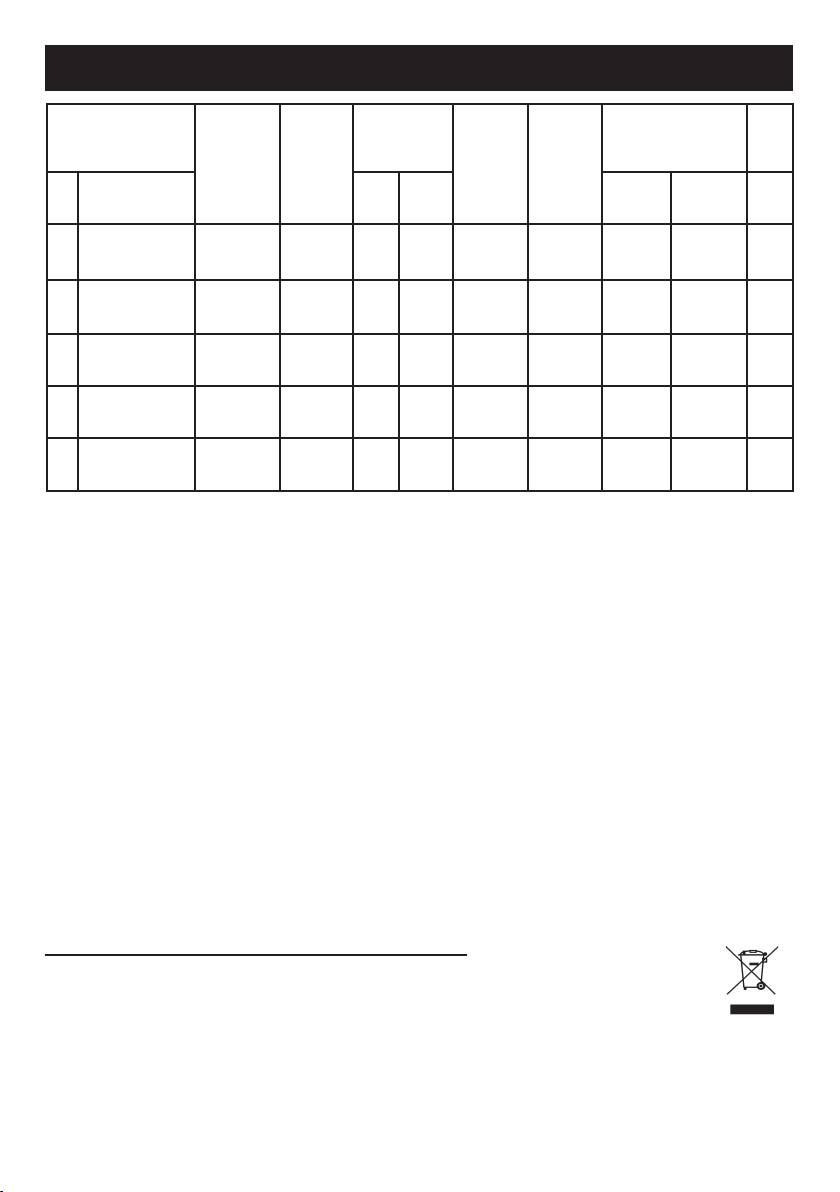
ТАБЛИЦА ТЕХНИЧЕСКИХ ХАРАКТЕРИСТИК
Диаметр
(EE
Рабочее
Диаметр
Производительность
Конфорки
Расход газа
байпаса
давление
форсунки
по теплу (Вт)
gas
вентиля
)
hob
Газ
№ Название мбар г/ч л/час 1/100 mm 1/100 mm Макс. Мин. (%) *
G30 - G31 28 - 30 225 - 85 42 3000 950
1 Быстрая
56.7
G20 20 - 290 115Y Reg. 3000 950
G30 - G31 28 - 30 126 - 65 31 1750 600
2 Полубыстрая
57
G20 20 - 165 97Z Reg. 1750 600
G30 - G31 28 - 30 71 - 50 27 1000 450
3 Вспомогательная
/
G20 20 - 99 72X Reg. 1000 450
G30 - G31 28 - 30 278 - 98 60 3800 2100
4 Тройная «Sabaf»
58.1
G20 20 - 367 135K Reg. 3800 2100
G30 - G31 28 - 30 255 - 93 60 3500 2100
Двойная
5
56.6
«корона» Defendi
G20 20 - 334 135 Reg. 3500 2100
Краткое название или ссылки на измерения и методов расчета, используемых для
установления соответствия вышеуказанным требованиям
Производительность каждого отдельного горелки рассчитывается в соответствии со стандартом EN
30-2-1 + A1: 2003 + A2: 2005
Общая эффективность плитой рассчитывается в соответствии с Регламентом ЕС 66/2014 пар. 2,2
Эффективность рассчитывается только для горелок с номинальной мощностью, превышающей
1,16 кВт (EN 30-2-1 + A1: 2003 + A2:. 2005; Номинал 4,1)
Информация, которая имеет отношение к клиентам свести к минимуму потребление энергии
во время использования
Советы по энергосбережению: Используйте кастрюли, имеющие плоское основание, используйте
горшки с правильного размера, и горшки с крышкой, уменьшить количество жидкости или жира,
когда жидкие закипит уменьшить настройку.
Этот прибор соответствует Директиве ЕС 2002/96/CE
Специальный знак, изображающий перечеркнутый мусорный контейнер, означает,
что этот прибор должен быть утилизирован отдельно от бытовых отходов согласно
существующим нормам. Вы поможете избежать отрицательных последствий для
окружающей среды и здоровью людей, которые могут быть вызваны неправильной
переработкой по окончании срока службы.
Утилизация прибора должна производиться в соответствии с действующим природоохранным
законодательством и правилами утилизации отходов.
Для получения более подробной информации по вторичной переработке этого прибора следует
обращаться в соответствующее ведомство (департамент экологии и охраны окружающей среды), в
службу очистки или в магазин, где Вы приобрели прибор.
23
ИНСТРУКЦИИ ДЛЯ ПОЛЬЗОВАТЕЛЯ
Все работы по установке, регулировке и переналадке для соответствующего
типа газа должны выполняться квалифицированным персоналом в соответствии
с действующими нормами. Специальные инструкции приведены в разделе,
предназначенном для установщика.
ПОЛЬЗОВАНИЕ ГАЗОВЫМИ КОНФОРКАМИ
- При приготовлении с использованием жиров
Символы, изображенные рядом с ручками,
и растительного масла будьте предельно
обозначают их соответствие определенным
внимательны, так как при перегреве они могут
конфоркам.
воспламеняться.
Автоматический розжиг без газ-контроля
- Не используйте аэрозоли вблизи работающей
Повернуть ручку конфорки против часовой стрелки
варочной поверхности.
до положения «максимум» (высокое пламя рис.1) и
- Чтобы избежать опрокидывания или вытекания
нажать на нее.
жидкости, не ставьте на варочную поверхность
Автоматический розжиг с газ-контролем
неустойчивые кастрюли или деформированные
Повернуть ручку конфорки против часовой стрелки
кастрюли.
до положения «максимум» (высокое пламя рис.1) и
- Проверьте, чтобы ручки кастрюль были повернут
нажать на нее.
таким образом, чтобы обеспечить безопасность.
После того как пламя загорится, нажимать ручку
- После розжига конфорки удостоверьтесь, что
примерно 6 секунд.
пламя ровное. Перед тем как снять кастрюлю
ВНИМАНИЕ: розжиг горелки тройная “корона”
следует уменьшить мощность пламени или
возможен только в позиции “МАКСИМУМ”.
выключить конфорку.
Рекомендации по пользованию газовыми
ОЧИСТКА
конфорками
Перед тем как приступать к работам по уходу и
Чтобы добиться максимальной эффективности
техническому обслуживанию, следует отключить
приготовления и экономии газа, рекомендуется
прибор от электрической сети.
для каждой конфорки использовать кастрюли
Не используйте паровые очистители для чистки
соответствующего диаметра (см. нижеследующую
варочной поверхности.
таблицу). Пламя не должно выбиваться из-под дна
Подождите, пока прибор остынет.
кастрюли (рис.2).
Эмалированные детали
Используйте максимальную мощность пламени,
Рекомендуется мыть эмалированные детали
чтобы быстро вскипятить жидкость и пониженную
теплым мыльным раствором или мягким моющим
мощность для подогрева пищи или для
средством. Не используйте абразивные или
продолжительного кипячения.
коррозийные средства. Не допускайте, чтобы такие
Положения ручки следует выбирать между
вещества как лимонный сок, помидоры, соленая
«максимумом» и «минимумом». Нельзя выбирать
вода, уксус, кофе и молоко подолгу оставались на
между «максимумом» и «выключено».
эмалированной поверхности.
Чтобы прервать поступление газа, поверните ручку
Детали из нержавеющей стали
по часовой стрелке до положения «выключено».
На деталях из нержавеющей стали могут
В случае отключения электроэнергии можно
появиться пятна, если они в течение длительного
зажигать конфорки при помощи спичек, установив
времени будут контактировать с жесткой водой
ручку в положение для розжига пламени (высокое
или с агрессивными моющими средствами.
пламя рис.1).
Рекомендуется мыть их мыльным раствором и
насухо вытирать мягкой тряпкой.
Мощность
Ø
Блеск сохранится, если регулярно использовать
Конфорки
(Вт)
кастрюли
соответствующие средства по уходу.
Конфорки и решетки
Вспомогательная 1000 10 - 14 cm
Чтобы было легче мыть решетки и крышки
рассекателей, их можно снять. Крышки
Полубыстрая 1750 16 - 18 cm
рассекателей можно мыть губкой, смоченной в
Быстрая 3000 20 - 22 cm
мыльной воде или в растворе мягкого моющего
средства. После мойки их следует насухо
Тройная 3800 22 - 24 cm
вытереть и аккуратно установить на место.
Проверьте, чтобы отверстия рассекателей не
Двойная «корона» 3500 18 - 20 cm
были закупорены. Постоянно проверяйте чистоту
зонда клапана безопасности (газ-контроля) и свечи
Внимание!
электророзжига. Это обеспечит их оптимальное
- Всегда проверяйте, чтобы ручки конфорок
функционирование. Решетки можно мыть в
находились в положении «выключено» (рис.1),
посудомоечной машине.
когда прибор не используется.
- Если пламя случайно погаснет, газ-контроль
автоматически прервет подачу газа. Для
повторного розжига установите ручку в положение
для розжига пламени (высокое пламя рис.1) и
нажмите на нее.
24
Газовые вентили
Когда станет трудно поворачивать ручку,
Смазку вентилей, если возникнет такая
следует приглашать мастера из сервисного
необходимость, должен выполнять только
центра.
квалифицированный специалист.
ИНСТРУКЦИИ ДЛЯ УСТАНОВЩИКА
ВАЖНОЕ ПРЕДУПРЕЖДЕНИЕ:
Описываемые ниже операции должны производиться квалифицированным персоналом в
соответствии с действующими нормами и правилами.
Производитель не несет ответственности за ущерб, возникший вследствие неправильной
установки прибора, нарушения приведенный правил.
УСТАНОВКА
Крепление варочной поверхности
Монтаж варочной поверхности
В комплекте к варочной поверхности
Прибор предназначен для встраивания в
прилагается специальная прокладка и набор
мебель, устойчивую к воздействию высоких
кронштейнов для крепления.
температур.
В зависимости от конструкции днища
Стенки мебели должны выдерживать
поставляется соответствующий тип кронштейна
температуру не менее 75°С плюс температура
(А или В). Для установки варочной поверхности
окружающей среды в соответствии с
выполните следующие операции:
европейскими нормами.
- Снимите решетки и крышки рассекателей.
Прибор относится к типу «Y», то есть может
- Переверните прибор и закрепите по его краям
устанавливаться, только если справа или слева
прокладку S (рис. 5).
от него находится только одна боковая стена.
- Вставьте варочную поверхность в отверстие
Следует избегать установки прибора вблизи
для встраивания и закрепите винтами V,
воспламеняющихся материалов вроде
вставленными в кронштейны крепления G
занавесок и т. п.
(рис. 6/6А).
В столешнице следует подготовить отверстие
для встраивания в соответствии с размерами,
Помещение для установки
указанными на стр. 3, при этом следует
Этот прибор не соединен с оборудованием для
предусмотреть, чтобы расстояние между краем
удаления продуктов горения. В помещении,
прибора и ближайшей стеной было не менее
где устанавливается варочная поверхность,
50 мм.
должна быть предусмотрена система
удаления продуктов сгорания. Это может быть
Модель Ширина (мм) Глубина (мм)
либо вытяжка, либо вентилятор на окне или
600 - 750 560 480
вентиляционном отверстии, включающиеся при
использовании прибора.
900 805 480
В помещении, где устанавливается прибор,
должен быть предусмотрен естественный
Если над варочной поверхностью предусмотрен
приток воздуха для нормального горения газа
монтаж вытяжки, она должна находиться от нее
и для вентиляции. Объем воздуха должен
3
на расстоянии не менее 760 мм.
составлять не мене 20 м
.
Рекомендуется изолировать варочную
Естественный приток воздуха должен
поверхность от мебели, в которую он
происходить напрямую через вентиляционные
встраивается, разделительной панелью,
отверстия в стене, либо посредством
оставив между ней и прибором расстояние не
воздуховода. Разрешается также применение
менее 10 мм (рис. 4).
непрямой вентиляции посредством вытяжки
Если варочная поверхность устанавливается
воздуха из помещений, прилегающих к кухне,
вместе с духовкой, следует принять меры
при условии соблюдения действующих норм.
предосторожности и обеспечить соблюдение
Минимальное сечение вентиляционного
2
правил безопасности. Особое внимание
отверстия должно составлять 200 см
.
следует уделить тому, чтобы шнур питания и
газовая труба не соприкасались с горячими
ПОДСОЕДИНЕНИЕ К ГАЗОВОЙ СЕТИ
деталями корпуса духовки. Кроме того, при
Перед тем как приступить к подсоединению
установке варочной поверхности над духовкой
прибора, следует проверить соответствие
без принудительной охлаждающей вентиляции
данных, указанных на маркировочной
следует предусмотреть внизу отверстия для
табличке с нижней стороны и на упаковке,
2
притока воздуха с сечением не менее 200 см
,
характеристикам газовой сети. Для проведения
а вверху выходные отверстия с сечением не
данной операции допущенный к работам
2
менее 60 см
.
установщик должен следовать указаниям,
25
приведенным в разделе «Переналадка под
ПЕРЕНАЛАДКА ПОД РАЗНЫЕ ТИПЫ ГАЗА
различные типы газа».
Замена форсунок
Подключение газа должно производиться при
Если изготовителем прибор налажен для
помощи жесткой металлической трубы или при
использования одного типа газа, а используется
помощи гибкой стальной трубы с неразрезной
другой, следует заменить форсунки конфорок.
стеной, характеристики которых соответствуют
Форсунки следует выбрать в соответствии
действующим нормам.
с приведенной в инструкции таблицей
В комплекте к некоторым моделям поставляются
технических характеристик.
два переходника: один цилиндрический и один
Для замены форсунок следует выполнить
раструбный (рис. 7). В зависимости от норм,
следующие операции:
принятых в стране, где устанавливается прибор,
- Снять решетки и крышки рассекателей.
следует выбрать соответствующий переходник.
- При помощи торцевого ключа на L отвернуть
При подсоединении к газовой сети не следует
форсунку U (рис. 8) и заменить форсункой,
оказывать воздействие на газовый контур.
соответствующей типу используемого газа.
После завершения подсоединения следует
- Крепко прикрутить форсунку.
проверить герметичность при помощи мыльного
Регулировка конфорок
раствора. Нельзя использовать для этих целей
Минимум должен быть всегда правильно
открытое пламя.
отрегулирован, а пламя не должно гаснуть
даже при резком переключении из положения
ЭЛЕКТРИЧЕСКОЕ ПОДКЛЮЧЕНИЕ
максимум в положение минимум.
Электрическое подключение должно
Если этого не происходит, необходимо
производиться квалифицированными
отрегулировать минимум, выполнив следующие
специалистами в соответствии с действующими
операции:
нормами.
- Зажечь конфорку;
Напряжение в сети должно соответствовать
- установить ручку в положение «Минимум»
напряжению, указанному в маркировочной
(маленькое пламя);
табличке на днище прибора.
- снять ручку вентиля;
Проверьте, чтобы электрооборудование
- вставить шлицевую отвертку в отверстие F
помещения было надежно заземлено в
вентиля (рис. 9-9/A) и повернуть винт байпаса
соответствии с действующими нормами.
до правильного положения минимума.
Прибор должен быть обязательно заземлен.
Если используется газ G30, винт байпаса
Если прибор не оснащен вилкой, к
должен быть закручен полностью.
шнуру питания следует подсоединить
соответствующую действующим нормам вилку.
ТЕКУЩЕЕ ОБСЛУЖИВАНИЕ
Для прямого подключения к сети следует
Замена шнура питания
предусмотреть установку устройства, которое
В случае необходимости замены шнура питания
обеспечит отключение от сети, с таким
следует использовать соответствующий
открытием контактов, гарантирующим полное
действующим нормам шнур типа H05VV-F или
отключение в условиях перенагрузки ІІІ
2
H05RR-F СЕЧЕНИЕМ 3 Х 0,75 мм
.
категории согласно нормативов по установке
Подсоединение к клеммной коробке следует
производить, как показано на рис. 10 и 10/А:
Провод L коричневый (фаза)
Провод N синий (ноль)
Провод желто-зеленый (земля)
Изготовитель не несет ответственности за возможные ошибки и неточности, допущенные
при печати данной инструкции. Рисунки, приведенные в инструкции, носят ориентировочный
характер. Изготовитель оставляет за собой право вносить в производимые им изделия
изменения, которые он сочтет необходимыми или полезными, в том числе в интересах
потребителя, без изменения основных функциональных характеристик и характеристик
безопасности.
26
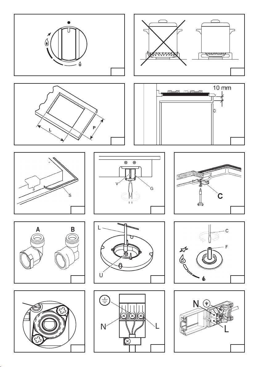
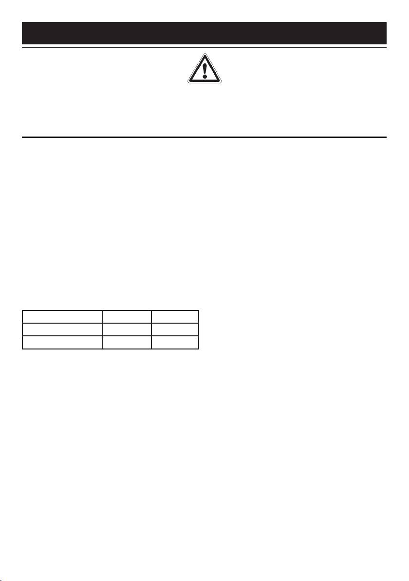
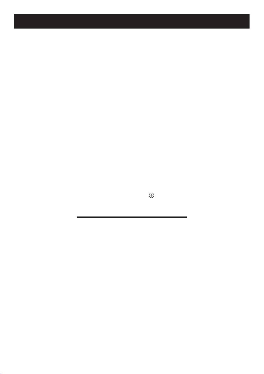
Chiuso - Closed
Fermé
Massimo
Maximum
Minimo
Minimum
1 2
3 4
5 6A 6
87
9
F
9/A
10 10/A

FOX s.p.a. di R. BOMPANI & C.
via Emilia est, 1465
41100 Modena - ITALY
www.bompani.it
