Bompani BO243CB/E: 88 - 88 88
88 - 88 88: Bompani BO243CB/E
5
1. GENERALITIES
WARNING :
Installation must be carried out by qualifi ed individuals, who must follow the instructions indicated in this booklet and
those provided for by law (Law n.46, dated 03/05/1990 - System Safety Standards).
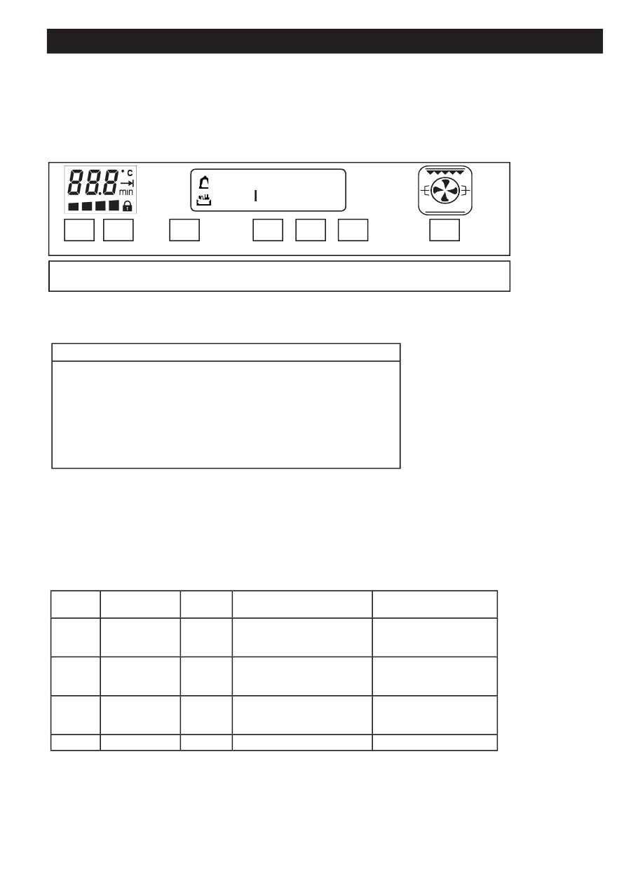
2. USER INTERFACE WITH TOUCH KEYS AND DISPLAY
- + Boost Time - + 0/I
7 6 5 4 3 2 1
88 - 88 88
A
2.1 Key functions
FUNCTION KEY (description from right to left)
1 0/I Turns on the oven and activates the -/+ key for cooking method selection
1 + 0-n Child safety: press the 0/I for 4 seconds
2 + Increases the time and selects the cooking method
3 – Decreases the time and selects the cooking method
4 Time: selects the time functions in sequence( see following table)
5 Boost: Fast pre-heat option
6 + Increases the temperature
7 – Decreases the temperature
Automatic repeat combined with the “-“ and “+” keys if kept pressed: one increment every 500 ms during the fi rst second, one incre-
ment every 200 ms to follow.
2.2. “Time” key cyclical functions
If repeatedly pressed, the following sequence will be displayed:
Pulse
Displayed after
pressing
Action
Display shows after 2 seconds Azione Utente tramite “+”
o “-”
1
( bell )
None
fl ashes as default value, other-
wise current value
Alarm signal time adjustment
Set alarm signal time
2
( dur )
None
fl ashes as default value, other-
wise current value
Alarm signal time adjustment
Set cooking length time
adjustment
3
( End )
None
the result between current
time/hour and length (default
or current) in fl ashing mode
Set cooking end time
4
( hour 9 )
None
Flashing clock
Set actual time (clock)
Instructions
GB

6
3. APPLIANCE OPERATION
When the control is fi rst turned on, the display shows the clock set at 12:00, which can be increased by one unit every minute. The
oven is off and the possible operations for unblocking it are: the “Clock setting” procedure or, in alternative, directly turning it on. The
detailed operations for setting the clock, the timer, duration, and end of cooking process are indicated in the relevant paragraphs that
follow. Through a single setting key, the oven cyclically enters into the display and modifi cation mode (shown on the fl ashing display),
in which the “+” and “-“ keys are activated to correct the value indicated on the display. This value is, however, accepted after 4 sec-
onds from the last time the key is pressed (the display stops fl ashing).
3.1. CLOCK SETTING
Scroll through the menu with the Timer Mode key until “hour” is displayed, and set it using the “+” and “-“ keys. The clock can only be
set with the oven in stand-by.
3.2. TURNING OVEN ON/OFF
Press and release the “O/I” key. “ON” will appear on the central display, the symbol lights up, as well as the light inside the oven. If
after a minute a cooking mode was not selected, the oven and the symbol turn off, and “OFF” will appear on the display. To turn the
oven off during cooking, press and release the 0/l key. With the key activated, it must be released at least 1” after being pressed.
3.3. TIMER
This function does not interact with loads, and it is always available regardless of the state the oven is in. Press the “Time” key, the
bell symbol lights up, and the display shows what is explained in paragraph 2.2. Set the desired value in minutes using the “+” and
“-“ keys, up to a maximum of 180 minutes. After 4 seconds without increasing or decreasing ,the information is accepted, and the bell
remains lit. Once the time set has lapsed, an acoustic signal is heard, and the bell symbol fl ashes. To stop both the acoustic signal
and the fl ashing symbol, just press any key; its associated function is normally not carried out (it is only needed to stop the signal).
3.4. SEMI-AUTOMATIC COOKING TIME FUNCTION
Turn the oven on, as indicated in paragraph 3.2. Pres and release the “Time” key, until “dur” appears. Set the time required for cooking
using the “+” and “-“ keys, up to a maximum of 180 minutes. Select a cooking function among those available, as indicated in paragraph
3.9: the oven will suggest a predetermined temperature. The temperature can be changed. After 4 seconds from the last time the key
was pressed, the oven turns on for the time set. After the time defi ned has ended, the oven enters the Cooking Ended mode.
3.5. SEMI-AUTOMATIC COOKING END FUNCTION
Turn on the oven as indicated in paragraph 3.2. Press the “Time” key until “End” appears. Use the “+” and “-“ to set the cooking end
time, which must occur within the next 23h59m. To enter the time, the same steps should be followed as those for the clock setting
(current time). After 4 seconds from the last time the key was pressed, the oven turns on for the time set. A cooking function among
those available can always be selected. The oven suggests a predetermined temperature. The temperature can be changed. Once
the time specifi ed has bee reached, the oven enters into the Cooking End mode
3.6. AUTOMATIC FUNCTION
Turn the oven on as indicated in paragraph 3.2. Press and release the “Time” key until “dur” appears. Set the cooking time required
using the “+” and “-“ keys, until a maximum of 180 minutes. Press the “Time” key again until “End” appears. Use the “+” and “-“ keys to
set the cooking end time, which must occur within the next 23h59m. After 4 seconds from the last time the key was pressed, the oven
enters the delayed start mode: it will then automatically turn on for the length of time specifi ed and will stop at the stop time specifi ed,
entering the Cooking end mode. Even during the delayed start phase, the temperature and the function are both displayed, and both
can be changed. All the oven loads are deactivated once the oven must start. The symbol will show the element selected, but will
maintain the light off symbol and the stopped fan symbol. The tangential fan runs according to the indications specifi ed in paragraph
0, while the oven light is separately illustrated in paragraph 3.13
3.7. COOKING END MODE
Once the timed cooking process has terminated, the oven turns off all the loads, and a triple intermittent acoustic signal of average
intensity is heard. The display temperature and functions turn off. The clock display shows the time, and the two “pot” and “auto”
symbols fl ash. To unblock the oven, just press any key among those positioned under the display: the acoustic signal stops, and the
oven is ready to receive new commands. It is possible to immediately select a new cooking function, or completely turn off the oven
by pressing the “O/I” .
Instructions
GB

7
3.8. CLOCK DISPLAY SYMBOLS
3.8.1. Pot
If lit, it indicates that the cooking function is active, even in manual mode. The “Light” and “Defrost” functions are not considered cook-
ing functions, therefore, it remains off. If this symbol is fl ashing, it indicates the end of the timed cooking phase. During the delayed
start mode, it remains off, and then lights up when cooking starts.
3.8.2. Auto
This is normally off. If lit, it indicates that a cooking time has been selected (the oven is not in manual mode), therefore, it is completed
with the
Pot
symbol. If fl ashing, it indicates the end of the timed cooking phase.
3.8.3. Bell
Normally off. If lit, it indicates that the timer is active. If fl ashing, it indicates that the timer has end.
Instructions
GB
8
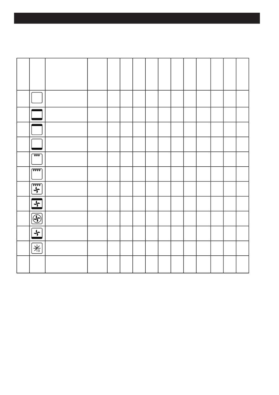
3.9. COOKING MODES SELECTION
By pressing the “+” or “-“ key, what is indicated in column 1 appears on the central display of the clock for 3 seconds ever 10 (al-
ternating with the clock), on the symbol, what is indicated in column 2 appears on the symbol, and the default value appears on the
temperature display.
Functions electric
oven
On
Light
X
---
---
---
160
110
Pr 01
Oven Static
X
X
X
50
200
250
200
110
Pr 02
Top heating element
X
X
50
200
250
160
110
Pr 03
Bottom heating ele-
ment
X
X
50
200
250
200
110
Pr 04
Grill
X
X
X
L1
L2
L5
160
110
Pr 05
Grill strenghened
X
X
X
X
L1
L4
L5
160
110
Pr 06
Grill strenghened fan
X
X
X
X
50
180
200
160
110
Pr 07
Oven Static + fan
X
X
X
X
50
175
250
200
110
Pr 08
Oven fan circular
X
X
X
50
175
250
200
110
Pr 09
Pizza (Bottom + fan)
X
X
X
50
200
250
200
110
Pr 10
Defrost
X
0
dEF
0
---
110
FPH
- -
Circolar +Bottom + fan
<TBD>
X
X
X
---
---
---
160
110
Bottom heat-
ing
Top
heating
el.
Oven fan
Oven light
Rotisserie
.
Cooling fan
radiale
Tangential
fan
Tangential
fan
T. min.(°C)
T. default
(°C)
T. max (°C)
Grill
Safety device
In order to prevent the appliance from overheating, the oven is fi tted with a safety device tripped in the event of a main thermostat
failure. This cuts off the electricity supply: do not attempt to repair the fault yourself; call your nearest Service Centre.
The oven should be left to heat up for at least 10 minutes before food for cooking is placed inside it.
When cooking in fan mode, two shelves can be fi lled at the same time. However, if the amount or type of foods is changed, cooking
times also change
.
Instructions
GB
9
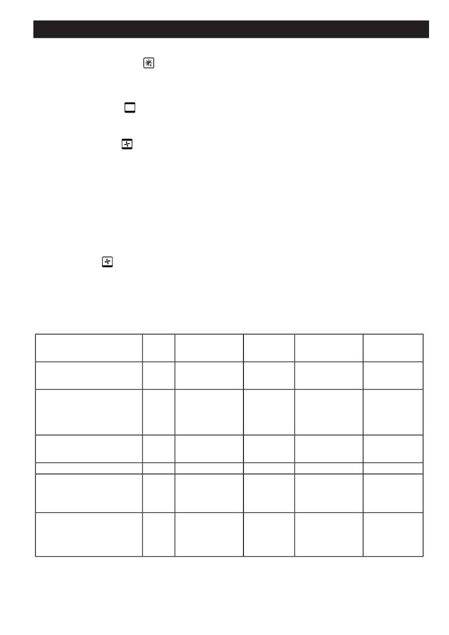
Using the cooking functions
Defrosting
Turn the selector knob to the symbol
and leave the thermostat on zero.The fan in the bottom of the oven circulates the air around
the food at room temperature.It is ideal for defrosting any type of food, but especially for delicate foods where no heat is required,
such as: frozen cakes, custard or cream cakes and fruit desserts.
Conventional Cooking
Turn the selector knob to the
symbol and set the thermostat on the temperature required. Heat is delivered from above and
below, and the food is cooked evenly.
Fan Cooking
Turn the selector knob to the
symbol and set the thermostat on the temperature required. In this cooking mode, the heat inside
the oven is circulated through it by a fan. This provides more uniform heat distribution, and thus gentler cooking. This function is also
useful for cooking several dishes at once, on different shelves. In this case the top runners and the third runners from the bottom
should be used. When cooking just one dish, place the shelf on the lowest runners for the best results. This function is ideal for cooking
souffl és, which need delicate, even cooking.
Cooking meat and fi sh
Meat can be placed in oven-dishes or pans, or straight on the shelf. If using only the shelf, ALWAYS pour a little water into the dripping
pan and fi t it onto the runners underneath the shelf. The dripping pan will collect the fats which melt during cooking, and the water
will prevent the fats from burning and generating unpleasant smells or smoke. White meat, poultry and fi sh generally require cooking
at a medium temperature (between150 and 250 degrees); to cook red meat “rare”, use temperatures between 200 and 220 degrees
for short times.
Cooking pizza
To cook pizza, use the
function: this programme uses the bottom heating elements and the fan. This combination heats the oven
quickly, with most of the heat delivered from underneath. If more than one shelf is used at a time, their positions must be swapped
halfway through the cooking process. The recommended temperature is 220° for an average cooking time of about 15-20 minutes.
Cooking confectionery
Cakes need a medium temperature, from 160° to 200° C. Before starting cooking, the oven should be left to warm up for about 15
minutes: try not to open the oven door once cooking has started.
Food for cooking
Weight
(kg)
Cooking shelf
position from the
bottom
Temperature
(°C)
Preheating
time
(minutes)
Cooking
time
(minutes)
Pasta :
Lasagne
Cannelloni
Paste au gratin
2.5
2.5
2.5
2
2
3
210
200
200
10
10
10
60-75
40-50
40-50
Meat :
Veal
Chicken
Duck
Rabbit
Lamb
1.7
1.5
1.8
2.0
1.8
2
2
2
2
2
220-250
200-220
200-220
200-220
200-220
10
10
10
10
10
120-160
45-60
100-110
70-80
90-95
Fish :
Mackerel
Dentex
Trout baked on paper
1.1
1.5
1.0
2
2
2
160-220
160-220
160-220
10
10
10
45-70
45-70
45-70
Pizza
: Neapolitan style
1.0
1-3
200-230
15
10-20
Cake :
Biscuits
Fruit tarts
Quiches
Ckes with yeast
0.5
1.1
1.0
1.0
2-3
2-3
2-3
2-3
160-180
160-180
160-180
165
15
15
15
15
30-50
30-50
30-50
30-50
Grilling:
Spit-roast veal
Spit-roast chicken
Hamburger
Mackerel
Toasted sandwiches
1
1,5
1
1
n° 4
2
2
2
2
2
-
-
-
-
-
5
5
5
5
5
15-20
20
7
15-20
5
NB:
Cooking times are guideline and may be varied to suit personal taste.
Instructions
GB

10
3.9.1. Special Booster Fast Pre-Heat <TBD> Program
The special Booster program allows for fast pre-heating of the oven through a particular combination of loads that are active during
pre-heating.
Specifi cities of the Booster mode:
- Can only be selected if a timed cooking mode is not programmed
- Cannot be activated in during the following functions:
a) Grill
b) Double Grill
c) Defrost/Chafi ng area
To activate the Booster:
- press the BOOST key
- on the clock display, “BOOST” appears fl ashing
When the Booster is active:
- the symbol continues to display the function normally select, but the Power board is actually informed to carry out a different com-
bination of loads.
- The temperature indicated is free and can be further modifi ed.
- The function that will be carried out at the end of the Booster cycle cannot be changed.
When pre-heating has terminated, “BOOST” disappears, and the Power board carries out the function that is actually represented by
the symbol.
To deactivate the Booster after it was activated:
- Press “BOOST”. The Booster mode is deactivated, and the actual function is reset.
3.9.2. Special Booster Super-Fast Pre-Heat Program
Program that is an alternative to the traditional Fast Pre-Heat program. The loads selected are recurrent:
- Circulation + Fan for 15 seconds
- Grill + Top + Fan for 15 seconds (Top = upper resistance)
- Bottom + Top + Fan for 15 seconds (Bottom = lower resistance
3.10. COOKING TIME SELECTION
Using the “+” and “-”keys, the temperature varies between the minimum and the maximum expected for each cooking mode with
increments of +/- 1 degree that are shown on the temperature display.
3.11. OVEN OFF MODE AND RESIDUAL HEAT INDICATOR
When powered-up, and when there is no function selected, the temperature display and programs are normally off, while the timer
display shows the time.
If the oven is still hot when turned off, the temperature display indicates the residual heat.
The 4 level bar indicated the actual oven temperature:
i. If t_ probe > 200°C: 1st, 2nd, 3rd on; 4th fl ashes
ii. Se 200 > t_ probe > 150°C: 1st, 2nd on; 3rd fl ashes ; 4th off
iii. If 150 > t_ probe > 100°C: 1st on, 2nd fl ashes a; 3rd, 4th off
iv. If 100 > t_ probe > 50°C: 1st fl ashes; 2nd, 3rd, 4th off
v. If 50 > t_ probe: 1st, 2nd, 3rd, 4th off
3.12. «CHILD CARE » CONTROL LOCK FUNCTION
Keeping the
“ON/OFF”
key pressed for at least 6 seconds, the oven enters in the child safety mode. The display shows
“n--O”
followed
by
“On”
, and the time reappears. On the temperature display, the lock symbol will remain lit until the “Child Care” is active. If this
block is activated after any type of cooking setting (manual, semi-automatic, automatic), the settings programmed can be displayed,
but modifi cations cannot be made and
“n--O”
on the central display will be a reminder that the function is active.
Manually or automatically turning the oven off will not deactivate the control lock mode. To deactivate, the
“ON/OFF”
key must be
pressed for at least 6 seconds. The display shows
“n--O”
, followed by
“OFF”
, then the time reappears.
When the oven is blocked, it cannot be turned on by pressing the
“O/I”
key.
3.13. OVEN LIGHT CONTROL
Once the desired function has been chosen, until the end of the pre-heating cycle, the oven light remains lit. After 3 minutes, the oven
light turns off. While waiting for the delayed start mode, the oven light remains off.
The oven light turns on automatically once any key is pressed (and its associated theoretic function is not carried out), then it turns
off after 1 minute.
Instructions
GB

11
3.14. PRE-HEATING BAR
This bar furnishes pre-heating indications, and signals the heating phase when cooking is in process. During the pre-heating phase,
the 4 level bar visually indicates what remains to reach the requested set-point:
i. If k > 75%: 1st, 2nd, 3rd on; 4th fl ashes
ii. If 75% > k > 50%: 1st, 2nd on; 3rd fl ashes; 4th off
iii. If 50% > k > 25%: 1st on, 2nd fl ashes; 3rd, 4th off
iv. If 25% > k: fl ashes; 2nd, 3rd, 4th off
At the end of the pre-heating phase, and during the cooking phase, the bar always remains lit: 1st,2nd,3rd ,4th on
3.15. TANGENTIAL FAN CONTROL
3.15.1. Select a cooking cycle
The tangential turns on, regardless of the central oven temperature, after 15 minutes from selection or, however, even before, if the
temperature detected on the probe is higher than the “power threshold” value. During the “DEFROST” function, the tangential fan is
immediately activated.
3.15.2. Cooking cycle stop (Off, stand-by)
When a cooking cycle ends, an observation phase begins, which lasts 20 minutes, during which the tangential is turned off if the
temperature is lower than the “power threshold” value.
After these 20 minutes, the tangential remains off, regardless of the temperature.
3.15.3. Power board sensor automatic function
A temperature sensor is installed on the Power board. When it detects a value >80°C, the tangential is forcedly activated, regardless
of the previous logistics.
3.16. ANNULLING COOKING END AND LENGTH SETTINGS
The cooking length and cooking end can be annulled by pressing the Funz + key during the cooking length setting phase: the oven
remains on and is automatically set to the indefi nite time manual function mode, as described in the paragraph (…)
Otherwise, the oven can be turned off completely by pressing the ON/OFF key.
3.17. ANNULLING TIMER SETTINGS
During the timer setting phase, the current value can be annulled by pressing the Funz - key.
4. CARE AND CLEANING
Kindly ignore the sections relating to accessories or instruments not featured on the appliance you have purchased.
4.1.
Cleaning
Oven Cleaning Advice
• The fi rst rule is to clean the oven often. For natural cleaning, use only hot water with bicarbonate of soda and/or lemon juice and/or
white wine vinegar dissolved in it.
• Do not use steam-cleaners.
• Detergents should not be sprayed straight onto the controls area; use a sponge.
• Never clean glass when still hot as the temperature difference may cause it to shatter. Always wait for glass to cool down to
lukewarm.
• Never use those cleaning products which contain caustic soda, solvents or many other harmful substances, since there is a risk
that they might not be completely removed after use, and the residues left in small cavities within the oven might be released onto
the foods cooked later.
• To clean an oven which is not very dirty, wipe half a lemon over the surface, leave to dry and then wipe with a damp sponge to
remove the residues of dirt and lemon juice.
• If the oven is very greasy, put a pan containing two litres of hot water containing a spoonful of ammonium inside and leave it over-
night. Wipe the grease off with a sponge next morning.
• If you are going to cook particularly greasy foods, deposits can be prevented by protecting the bottom of the oven with a sheet of
aluminium foil, which can easily be removed with the grease residues at the end of the process.
• When using detergents, keep the environment in mind and follow the producer’s instructions. The market now offers a variety of
concentrated solid or liquid detergents with lower environmental impact.
• The oven should be rinsed with plenty of water and dried after cleaning.
• Except for the runners, the oven accessories can be washed in the normal way, even in the dishwasher.
• For superfi cial scratches, apply a special cleaner/polish for stainless steel, using a soft cloth.
• Do not use silver-cleaning products .
Instructions
GB

12
Cleaning Stainless Steel
Care and cleaning of the oven you have purchased are important to keep the steel bright and uniform over time. The stainless steel
used for the manufacture of our ovens is Silver Ice, fi nished with a special anti-fi ngerprint treatment that keeps it shiny even after use.
We advise you never to use abrasive sponges, scouring pads, wire wool, acids or products which might scratch the surface. Clean
it with soft cloths and ordinary, absolutely non-abrasive washing-up liquid; creams are not recommended because they contain tiny
abrasive particles which might leave marks on the steel.
Cleaning Enamel and Glass
Enamel is a vitreous fi nish with excellent resistance to heat and acids. Like glass, it may be damaged by prolonged contact with acids, so
spills of tomato sauce, lemon and vinegar should be wiped off immediately. Use bicarbonate of soda or non-abrasive cream cleaner
for the most stubborn stains. Never use descaler products: they might cause irreparable damage to the enamel. Oven interiors are
also enamelled and must be cleaned using specifi c products, easily available from retailers. It is best to clean the oven after each
use, while still warm. We advise you not to allow dirt to build up over time since it is more diffi cult to remove layers of dirt and there is
a risk of leaving permanent marks on the enamel.
Cleaning the Door Glass
All ovens are fi tted with glass doors with innovative, extremely convenient characteristics. The full-glass on the inside can be removed
easily without the aid of any tools: the screw-free visible fi xing system guarantees that the door provides the easy cleaning only glass
can ensure. Proceed as follows to remove the glass in the oven door correctly.
• Fully open the door;
• apply gentle leverage with a coin or a fl at-head screwdriver in the two recesses in the bottom of the inside of the door simultaneou
sly;
• released from its seat, the glass can be extracted from the recess into which it is fi tted:
• After cleaning, repeat the same procedure in reverse order.
WARNING:
Take care to reassemble the pieces of glass in the correct order; the inside glass has a special heat-refl ecting fi nish!
Do not clean the glass door of the oven with rough, abrasive materials or sharp metal scrapers, since they may scratch the surface
and cause the glass to shatter.
4.2. Maintenance
• Disconnect the appliance from the electrical mains by disarming the fuses before carrying out any cleaning or servicing opera
tions.
• In the event of failure, please fi rst of all check the fuses of the household electricity supply system.
• If the problems are not caused by the power supply, kindly contact your Authorised Service Centre , stating the model of the appliance
and the serial number stated on the nameplate.
• To ensure that the appliance’s safety characteristics are not impaired, all maintenance work must be carried out by authorised
personnel.
• Improper maintenance work will result in forfeiture of warranty rights .
Changing the oven light bulb
To replace the oven light bulb, follow the instructions provided below:
1. Switch the oven off and disconnect it from the power supply. The bulb is in the top right-hand corner of back wall of the oven;
2.Make sure that the oven is cold and unscrew the glass cover;
3.Unscrew the light bulb and replace it with another of the same type;
4.Screw the glass cover fi rmly back into place.
Removing the oven door
This procedure must only be carried out by qualifi ed staff, since it may involve safety risks for the user.
The door can be removed by proceeding as follows:
1.Fully open the door;
2.Insert two small coins (e.g. 10 Eurocents) into the two slots in the hinges, and close the door until the coins have been pushed
almost fully home (see fi g.). Handle the door and hinges with great care while the coins are inserted.
3.Lift the door off, holding it at the sides and moving it slightly forward.
4.To put the door back in place, return the hinges to their positions, checking that they have fi tted into their seats; lower the door
completely and remove the coins inserted earlier.
5.Close the door again to the fully closed position.
Changing the Oven Door Gasket
Always inspect the oven door gasket and order a replacement from the after-sales service without delay if worn.
Instructions
GB

13
5. REGULATIONS, GENERAL SAFETY AND ENVIRONMENTAL PROTECTION
5.1.
REGULATIONS
5.1.1 DISPOSAL: PACKAGING AND DECOMMISSIONED APPLIANCE
• The user is responsible for consigning the obsolete appliance to his disposal facility; otherwise, he will be liable to prosecution under
the relevant waste disposal legislation.
• Appropriate separate disposal ready for recycling of decommissioned appliances, and environment-friendly processing and disposal
of waste, help to prevent possible harmful impacts on the environment and health and encourage the recycling of the materials of
which the product consists.
• For more detailed information on the waste disposal systems available, contact your lo cal waste disposal service, or the shop from
which the appliance was purchased.
DIRECTIVE 2002/96/EC (WEEE): INFORMATION FOR USERS
This information is intended only for the owners of appliances which carry the symbol shown in Fig. A on the adhesive technical data
label fi tted to the product (serial number label).
This symbol indicates that the product is classifi ed, under the relevant regulations as electrical or electronic equipment and is compliant
with EU Directive 2002/96/EC (WEEE). Therefore, at the end of its useful life, it must be handled separately from household waste;
it can be consigned free of charge to a recycling centre for electrical and electronic equipment or returned to the dealer on purchase
of an equivalent new appliance.
Italian Decree Law 151/05, which implements the EU guidelines, extends the principle of Producers’ responsibility to the electrical
and electronic products sector. Producers are responsible for implementing and operating a system for disposing of the waste ge-
nerated by the electrical and electronic equipment they offer for sale. Producers are therefore responsible for collecting WEEE from
the collection points (public and private), transporting them to suitable treatment centres, and the subsequent recycling and reuse of
the materials.
Fig.A
5.1.2 MATERIALS IN CONTACT WITH FOODS. INFORMATION FOR USERS.
EUROPEAN REGULATION No 1935/2004: INFORMATION FOR USERS.
The symbol shown here, which appears on the packaging, indicates that the materials in this product which may come into contact
with food are compliant with the requirements of European Regulation No 1935/2004. This regulation is based on the principle that
materials or objects intended for direct or indirect contact with foods must be suffi ciently inert to rule out the risk of transfer of sub-
stances to the foods in quantities such as to put human health at risk or cause an unacceptable change in the foods’ composition or
a deterioration of their organoleptic characteristics.
Fig. B
* Foods might come into contact:
1.Inside the oven chamber, with oven shelves, dripping pans, confectionary trays, oven door glazing, rubber gaskets, and the sides
of the oven itself.
2.On the hob, with pan stands, burners and the hob skin.
3.In the food-warmer drawer, with the sides of the compartment.
5.2 GENERAL SAFETY
• This appliance is intended solely for domestic use. The oven must only be used for preparing food.
• The electricity supply must always be disconnected before any procedures inside the oven or where there is the risk of accessing
live parts.
• Never touch the oven door hinges without due care as injury may result
• The appliance must not be used by children or the differently able without supervision.
• Parents must avoid children to play with the appliance.
• The appliance becomes very hot during use. Care should be taken not to touch the heating elements inside the oven.
• Warning: accessible parts may become very hot during use, children should be kept at a safe distance.
• If the power supply cable is damaged it must be replaced by the producer, the after-sales service or a skilled person to avoid ha-
zards.
• The appliance becomes hot during use.
• Removal all packaging residues, e.g. any polystyrene fragments, from the oven.
• No responsibility is accepted for injury or damage deriving from poor installation or incorrect use of the appliance.
• Improper repairs are a source of danger; repairs must only be performed by technical staff who have been suitably trained by the
manufacturer.
• In the event of malfunctions, contact the after-sales service without delay.
Instructions
GB

14
WARNING:
Do not touch the oven heating element.
WARNING:
Make sure that the appliance is switched off before changing the light bulb to avoid electric shock.
5.3 ENVIRONMENTAL PROTECTION AND SAVING
• Using the oven between late afternoon and early morning helps to reduce demand peaks.
• Keeping the oven door gaskets clean and in good condition, so that they adhere to the door fi rmly, reduces heat loss.
6.FOR THE INSTALLATION ENGINEER
The appliance must be installed by a qualifi ed person, who must follow the instructions provided in this manual and in the
regulations:Law n. 46 of 05.03.1990 – Regulations on the Safety of Systems
6.1. Technical Data
Heating Element Power
Bottom heating element
1100 W
Top - bottom heating element
1100-1500 W
Fan heating element
2000 W
Oven light
15 W
Cooling fan (where installed) 22-26 W
Oven fan 25 W
Power supply voltage (50-60Hz) 230 V
Oven usable dimensions
Width mm. 411
Depth mm. 391
Height mm. 330
Volume l. 58
Usable dimensions of cavity in building-in cabinet
Height mm. 584
Width mm. 564
Depth mm. 550
6.2 Pre-Installation Procedures
• Unpack the appliance and recycle the packaging material in accordance with the relevant regulations.
• After unpacking, check the appliance for damage. If in doubt, do not use the appliance and contact a qualifi ed professional. (See
After-Sales Service).
• The packaging materials (plastic bags, expanded polystyrene, nails, etc.) must not be left within reach of children since they are
potentially hazardous.
• Check that the accessories are in the bottom of the packaging.
• Do not make improper use of the oven door handle during transport and installation.
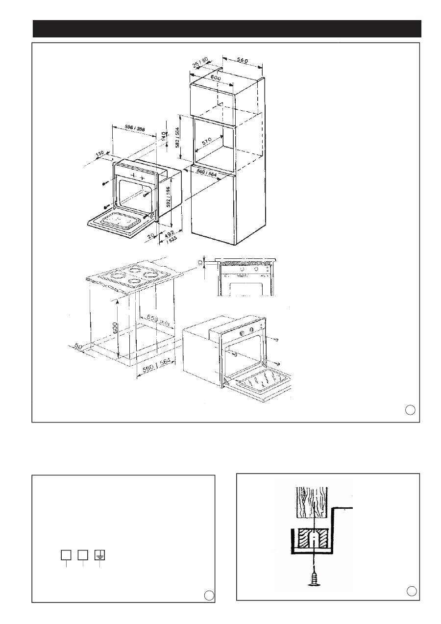
6.3 Building-In the Oven
• In order to allow the product to be built in correctly, the cabinet must have the following characteristics:
- the panels next to the oven must be in heat-resistant material;
- if the cabinet is in veneered wood, the adhesive used must withstand a temperature of 100°C;
- when building-in the oven, whether the installation is under-counter or in a tall unit, the cabinet must have the dimensions stated
in Fig. 1 – page 17
• Place the oven in the cabinet and screw the 4 screws fully down, using the holes provided in the facia, visible when the oven door
is opened. Make sure that the screws are inserted towards the centre of the wood in the cabinet: (see Fig.1-3-page 17). Before fi xing
the screws, also ensure that the oven is correctly aligned with the fl oor with the aid of a spirit level.
• An opening in the top of the tall unit, or a 10 mm gap above the oven surround, should be provided to ensure adequate ventilation.
(see Fig. 1 - page 17).
• If the oven is to be installed close to another appliance, check that there is no interference between the two devices when in ope-
ration.
• Once the appliance has been built in, no contact with electrical parts must be possible.
6.4 Connecting to the electrical mains
For direct connection to the mains, a mains cut-off device with a contact breaking gap that ensures complete disconnection in category
lll overvoltage conditions must be provided, in accordance with the installation rules.
WARNING:
The plug must be reachable when the appliance is installed.
Useful information for the installation engineer:
• the green-yellow coloured wire must be used to make the earth connection;
• the blue wire for the neutral;
• the brown wire for the live connection;
• the cable must not touch hot surfaces with a temperature over 75°C;
• if the cable is replaced, the new one must be of H05RR-F or H05V2V2-F type of suitable gauge (see Fig. 2 – page 17);
Instructions
GB

15
• if the appliance is supplied without a cable, use a type H05RR-F or H05V2V2-F cable of suitable gauge (see Fig. 2 – page 17);
The installer is responsible for making the electrical connection correctly and for compliance with safety regulations. The electrical
connection diagrams are provided in Fig. 2 – page 17.
IMPORTANT WARNING:
The manufacturer cannot be held responsible for any damage caused by failure to comply with the instructions provided and the
relevant regulations and standards
.
7. GENERAL PRECAUTIONS
7.1. Oven Accessories
The accessories provided in the oven are:
1. The shelf, which supports the pans for cooking confectionery or roasts, or on which meat for grilling is placed directly.
2. The drip pan under the grill is used to collect juices, which drip from the food that is cooked directly on the grill. The drip pan can
also be used for cooking.
7.2. “Pull-Out Oven Runners” Kit
Some versions of the appliance are fi tted with telescopic runners.
They are extremely convenient when cooking, since they allow shelves to be pulled right out, and stopped in the fully extracted position.
This convenient aid allows foods to be checked with no risk of burns, and ensures more thorough cleaning.
The oven can be fi tted with a “Pull-Out Runner” kit on request.
This optional can be ordered from your deale
r.
8. ASSISTANCE – DIAGNOSTIC MODE
When the oven is in the Power-up state (fl ashing clock), the test mode can be activated by simultaneously pressing the TEMPER+
and the EDITION+ keys for 5 seconds.
8.1. Phase 1 – Display Board
All the display segments are all turned on. If a key is pressed, the code associated to this key is temporarily displayed, to then return
to display all the segments. The automatic repetition is activated for keys equipped with this function.
If a key is not pressed for approx. 10 seconds, the oven passes to the next phase.
8.2. Phase 2 – Power Board
The clock display shows “8888” with the symbols fl ashing, while the display shows the temperature read by the oven probe. The
symbol is off. By pressing a key, the associated code is shown on the clock display.
The Double Cut relay is kept closed, and all the other relays are cyclically activated, one at a time. Once the last relay is reached, the
cycle starts over.
If a key is not pressed for approx. 10 seconds, the diagnostic phase is terminated and the oven returns to the Power-up phase.
9. MALFUNCTION SIGNALS
9.1. Detecting malfunctions
When a malfunction occurs, the control system begins to monitor this signal and considers it plausible only if it persists for more than
1 minute. If during this minute another malfunction presents itself, the system considers it plausible if it persists for more than 4 se-
conds.
When the malfunction is plausible, the system passes to the Malfunction display mode: the oven is off, all the loads are deactivated,
and the “Err” message appears, alternating with the type of malfunction detected:
“Shor” : oven probe in short circuit
“OPEN”: oven probe in open circuit and not connected
“ntc1” : thermal probe on Power board
During this phase, the malfunction signal can be “annulled” by pressing any key: if the malfunction is still present, everything returns
to the display mode after 1 minute.
If the malfunction is not autonomously resolved, the control continues to indicate “Err”, without any additional explanation.
If a probe malfunction occurs, the system reacts as if a temperature higher than 500°C has been reached.
Instructions
GB

16
Instructions
GB
9.2. Over-heating
When the thermal probe on the Power board detects a room temperature of >100°C, all the thermal elements of the oven automatically
turn off. If this persists for more than 1 minute, the clock display shows “STOP”, and every command on the key board is ignored until
the temperature goes below this limit.
17
Figures
GB
11
CONNECTION DIAGRAM
230 V TWO-PHASE
Wire gauge:
> 3,5 kW
3x2,5 mm
2
2,2 - 3,5 kW
3x1,5 mm
2
0 - 2,2 kW
3x1 mm
2
1
2
L
N
22
33

BOMPANI ITALIA Spa. - Via Emilia Est, 1465
41100 Modena - Italy
Tel + 39 059 282278 - Fax +39 059 281774
www.bompani.it - bompani_italia@bompaniitalia.it

NOTICE D'UTILISATION FO UR
“ ELECTRONIC OVEN ”

2
FR
1. GENERALITES................................................................................................................................................. .............................5
2. INTERFACE UTILISATEUR AVEC TOUCHES TOUCH ET DISPLAY............................................................................. .........5
2.1. Fonctions des touches .............................................................................................................................................. ................ 5
2.2. Fonctions ciycliques de la touche “Time” .................................................................................................................... .............. 5
3. FONCTIONS CYCLIQUES DE LA TOUCHE “ TIME “ .................................................................................................... ............6
3.1. RELAGE DE L’HORLOGE.................................................................................................................. ....................................... 6
3.3. MINUTEUR ............................................................................................................................................... ................................. 6
3.4. FONCTIONNEMENT SEMI-AUTOMATIQUE DE LA DUREE DE CUISSON................................................................... ......... 6
3.5. FONCTIONNEMENT SEMI-AUTOMATIQU DE FIN DE CUISSON .......................................................... ............................... 6
3.6. FONCTION AUTOMATIQUE................................................................................................................... ................................. 6
3.7. MODALITE FIN DE CUISSON................................................................................................................. .................................. 6
3.8. ICONE DU DISPLAY HORLOGE .................................................................................................................... .......................... 7
3.8.1. Casserole............................................................................................................................................... ................................. 7
3.8.2. Auto....................................................................................................................................................... .................................. 7
3.8.3. Cloche.......................................................................................................................................... ........................................... 7
3.9. SELECTION D’UN MODE DE CUISSON........................................................................................................... ....................... 7
3.9.1. Programme Spécial Booster FastPreHeat <TBD>............................................................................. ..................................... 8
3.9.2. Programme Spéciale Booster Super-FastPreHeat ............................................. ................................................................. 10
3.10. SELECTION TEMPERATURE DE CUISSON ...................................................................................... ................................ 10
3.11. MODALITE FOUR ETEINT ET INDICATION CHALEUR RESIDUELLE...................................................... ......................... 10
3.12. FONCTION DU BLOCAGE DES COMMANDES “CHILDREN CARE”................................................................... ............... 10
3.13. CONTROLE ECLAIRAGE DU FOUR ..................................................................................................................... ............... 10
3.14. BARRE DE PRECHAUFFAGE........................................................................................................................... .................... 10
3.15. CONTROLE VENTILATEUR TANGENTIEL ..................................................................................... .................................... 11
3.15.1. Sélection d’un cycle de cuisson............................................................................................................ ............................... 11
3.15.2. Arrêt d’un cycle de cuisson (Off, stand-by) ....................................................................................... ................................. 11
3.15.3. Fonctionnement automatique de la sonde Fiche Power........................................................................... ........................ 11
3.16. ANNULATION DES REGLAGES DUREE ET FIN DE CUISSON ....................................................... .................................. 11
3.17. ANNULATION DES REGLAGES MINUTEUR.............................................................................. ......................................... 11
4 NETTOYAGE ET ENTRETIEN .....................................................................................................................................................11
4.1 Nettoyage ...................................................................................................................................................................................11
4.2 Entretien .....................................................................................................................................................................................12
5. NORMES,
SÉCURITÉ GÉNÉRALE ET RESPECT DE L’ENVIRONNEMENT ..........................................................................13
5.1. NORMES ...................................................................................................................................................................................13
5.1.1 Élimination: emballage et appareil inutilisable .........................................................................................................................13
5.1.2. Matériaux en contact avec aliments .......................................................................................................................................13
5.2. SÉCURITÉ GÉNÉRALE ............................................................................................................................................................13
6. POUR L’INSTALLATEUR ...........................................................................................................................................................14
6.1. Carattéristiques techniques .......................................................................................................................................................14
6.2. Avant le montage .......................................................................................................................................................................14
6.3. Four encastré ............................................................................................................................................................................14
6.4. Branchement électrique .............................................................................................................................................................15
7. CONSEILS D’ORDRE GENERALE .............................................................................................................................................15
7.1. Accessoires du four ...................................................................................................................................................................15
7.2. Kit “Glissières de four extractibles” ............................................................................................................................................15
8. MODALITE DIAGNOSTIC ............................................................................... ...........................................................................15
8.1. Phase 1 – Display Board...................................................................................................................... .................................... 15
8.2. Phase 2 – Power Board ....................................................................................................................... .................................... 15
9. SIGNALIMENT D’ANOMALIES.............................................................................................................. .....................................16
9.1. Relèvement d’anomalies ....................................................................................................................... .................................. 16
9.2. Surchauffe ....................................................................................................................................... ........................................ 16
Figures ..............................................................................................................................................................................................17
Index

3
Nous tenons à vous remercier d’avoir choisi l’un des fours BOMPANI ITALIA. Ce nouveau produit, conçu et fabriqué avec des
matériaux de qualité, en alliant innovation et technologie, vous aidera dans la réalisation de vos recettes. Nous vous prions de lire
attentivement les instructions très faciles qui vous permettront d’atteindre d’excellents résultats dès la première utilisation.
Elles contiennent des informations importantes pour la sécurité, l’utilisation et l’entretien de votre appareil.
Cette notice est prévue pour les différentes versions du produit. Tenez compte uniquement des paragraphes qui concernent les ac-
cessoires et l’instrumentation présents dans le produit que vous avez acheté.
BOMPANI ITALIA ne sera pas responsable des dommages occasionnés aux choses et aux personnes dérivant d’une mau-
vaise installation ou de l’utilisation inappropriée de l’appareil.
Pour d’éventuelles commandes de pièces de rechange, la demande au revendeur doit comprendre le n° du modèle et le n° de série
reportés sur la plaquette visible lorsqu’on ouvre la porte du four.
Les fabricants d’électroménagers doivent se conformer à différentes normes ; c’est dans cet objectif que BOMPANI ITALIA produit
ses appareils et, lorsque cela est possible, prévoit des innovations pour améliorer la sécurité et le respect de l’environnement.
Tous les produits BOMPANI ITALIA sont donc conformes :
• à la directive 2006/95/CE qui concerne les produits électriques alimentés à Basse Tension. La directive impose que tous les matéri-
els électriques et électroniques destinés à être utilisés à des tensions entre 50-1000Vca et entre 75-1500 Vcc soient fabriqués
conformément à la règle de l’art en matière de sécurité, aussi bien en milieu domestique qu’industriel. La Directive s’applique en
général aux appareillages électriques et sert à éviter tout risque lié à l’utilisation du courant électrique ;
• au RÈGLEMENT EUROPÉEN 1935/2004 relatif aux matériaux et aux objets destinés à être en contact avec les denrées alimen-
taires ;
• à la directive 2002/95/CE relative à la limitation ou l’interdiction de l’utilisation de certaines substances dangereuses, conscients du
fait que la valeur d’un produit se construit aussi sur la valeur sociale que celui-ci génère ;
• à la directive 2002/40/CE, la norme de référence qui applique la vieille directive 92/75/CEE sur l’indication de la consommation
d’énergie des fours électriques à usage domestique ;
• à la directive 2004/108/CEE qui concerne la compatibilité électromagnétique. Cette directive se propose de réglementer les sig-
naux émis par les appareils pendant leur fonctionnement normal ainsi que la protection contre tout dommage des réseaux publics
de télécommunication ;
• à la directive 2002/96/CE relative aux déchets d’équipements électriques et électroniques (DEEE), conscients que la récolte dif-
férenciée appropriée pour la remise de l’appareil au recyclage, au traitement et à l’écoulement environnemental compatible con-
tribue à éviter des effets négatifs possibles sur l’environnement et la santé et favorise le recyclage des matériaux qui composent le
produit.
FR
Introduction

4
AVANT D’UTILISER L’APPAREIL LIRE ATTENTIVEMENT LES INSTRUCTIONS ET LES CON-
SERVER POUR TOUTE CONSULTATION FUTURE
POUR VOTRE SÉCURITÉ
Tout utilisateur est responsable de l’utilisation correcte et du parfait état du produit acheté.
• Si l’appareil est endommagé, ne pas l’utiliser (voir Assistance)
• Pour toute réparation, s’adresser uniquement à un Centre agréé par le fabricant et exiger des pièces de rechange d’origine. Le
non respect de ce qui est reporté ci-dessus peut compromettre la sécurité de l’appareil.
• Le branchement de l’appareil ne peut être effectué que par du personnel autorisé, conformément aux normes en vigueur concer-
nant l’alimentation électrique et aux normes de construction des différents pays.
• Avant toute opération de nettoyage ou d’entretien, débrancher l’appareil.
• Pour enlever la fiche de la prise de courant, ne pas tirer le câble d’alimentation, mais l’enlever délicatement pour éviter la rupture
des fils électriques à l’intérieur de la fiche.
• Éviter de placer les câbles de l’alimentation en contact avec des parties qui chauffent pendant l’utilisation ou qui pourraient être
écrasées.
• Ne pas conserver dans le four des objets inflammables, explosifs et qui ne résistent pas à la chaleur tels que, papier, chiffons ou
détersifs, parce qu’ils peuvent prendre feu à l’allumage du four.
• Bien que notre produit soit conforme aux normes en matière de respect des températures superficielles (porte froide), il est con-
seillé d’éloigner les enfants du bandeau de commandes et de la porte du four lorsque celui-ci est en marche.
• Pour mettre ou prendre les récipients, enfiler toujours des gants thermiques spéciaux.
• Surveiller toujours la cuisson parce que les graisses utilisées sont facilement inflammables. Éliminer les dépôts de graisse et les
autres résidus d’aliment avant d’utiliser de nouveau le four.
• Sur la porte ouverte du four, ne jamais poser d’objets lourds car les charnières pourraient s’abîmer.
• Les dommages causés par l’inobservation de ces instructions ne rentrent pas dans le droit de garantie.
Première mise en marche
• Avant toute opération de nettoyage ou d’entretien, débrancher l’appareil.
• Retirer les accessoires du four.
• Enlever complètement du four les résidus de l’emballage, par ex. des fragments de polystyrène.
Puis procéder comme suit :
1.Retirer les grilles du four.
2.Nettoyer le four et les accessoires avec une solution de lavage commerciale bien chaude
3.Passer un chiffon doux humide à l’extérieur.
4.Remonter les grilles.
5.Avant d’utiliser le four pour la première fois, le faire chauffer à vide pendant au moins 30 minutes avec le thermostat au maximum
et la porte fermée. Puis éteindre, ouvrir la porte du four et aérer la pièce. L’odeur que l’on sent est due à l’évaporation des sub-
stances utilisées pour protéger le four.
Choisir des solutions commerciales qui ne sont pas nocives pour l’environnement et pour la santé, en évitant les produits avec des
composants chimiques inutilement agressifs.
Pour les nettoyages suivants, voir les instructions du chapitre 4.
Avant la mise en marche, contrôler minutieusement que l’appareil n’ait pas subi de dommages.
Si les endommagements du produit sont dus au transport, le communiquer dans les plus
brefs délais au Centre d’assistance de compétence le plus proche de la zone de résidence.
ATTENTION: La réparation en garantie pour des dommages esthétiques n’est possible qu’au moment de la livraison et de la
première mise en marche de l’appareil électroménager. L’acheteur doit donc vérifier s’il est en bon état. En cas d’anomalies, ap-
peler le technicien sans retard, en suivant les modalités du fabricant fournies dans le chapitre « Assistance ».
Instructions
FR
