ASRock Z77 Extreme11 – страница 2
Инструкция к Материнской Плате ASRock Z77 Extreme11
2.3 Installing Memory Modules (DIMM)
This motherboard provides four 240-pin DDR3 (Double Data Rate 3) DIMM
slots, and supports Dual Channel Memory Technology. For dual channel
conguration, you always need to install identical (the same brand, speed,
size and chip-type) DDR3 DIMM pairs.
1. It is unable to activate Dual Channel Memory Technology
with only one memory module installed.
2. It is not allowed to install a DDR or DDR2 memory module
into a DDR3 slot; otherwise, this motherboard and DIMM
may be damaged.
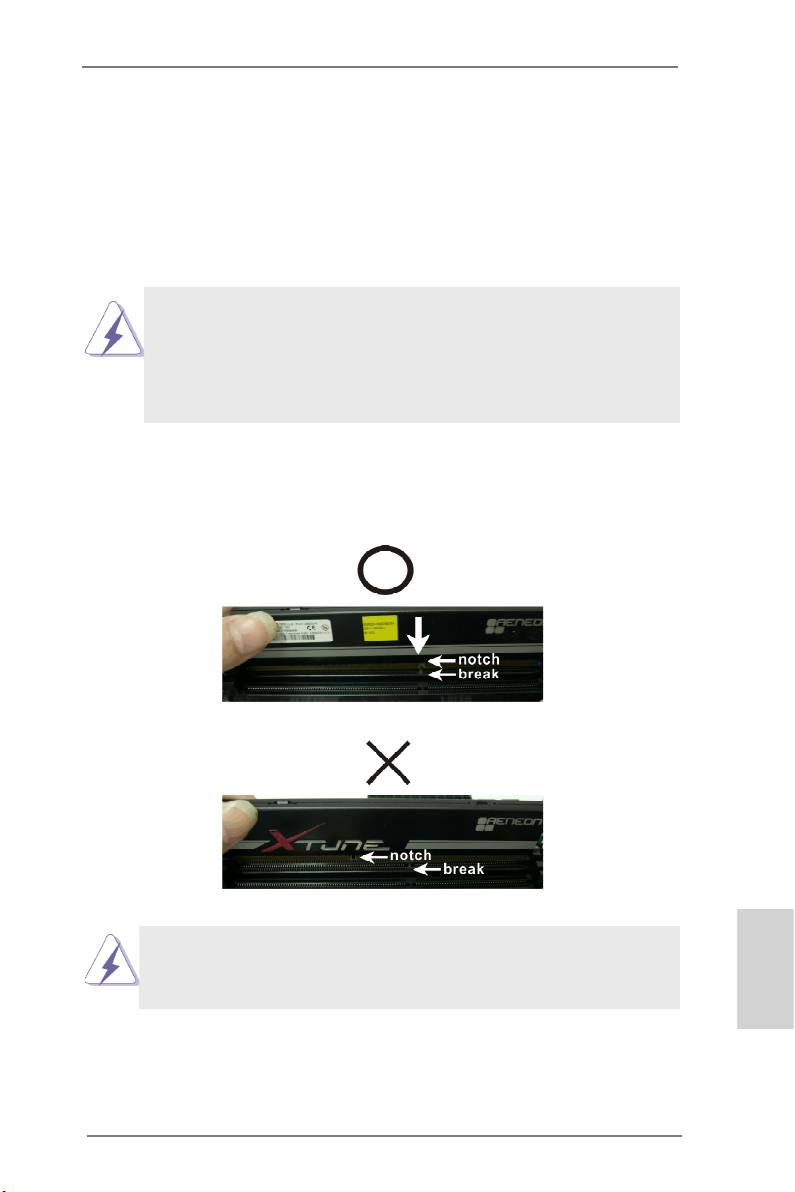
Step 1. Unlock a DIMM slot by pressing the retaining clips outward.
Step 2. Align a DIMM on the slot such that the notch on the DIMM
matches the break on the slot.
The DIMM only ts in one correct orientation. It will cause per-
manent damage to the motherboard and the DIMM if you force
the DIMM into the slot at incorrect orientation.
English
Step 3. Firmly insert the DIMM into the slot until the retaining clips at both
ends fully snap back in place and the DIMM is properly seated.
21
ASRock Z77 Extreme11 Motherboard
2.4 Expansion Slots (PCI Express Slots)
There are 7 PCI Express slots and 1 mini_PCI Express slot on this moth-
erboard.
Mini-PCIE Slots: MINI_PCIE1 is used for mini-PCIE cards.
PCIE slots: PCIE2, PCIE4 and PCIE6 (PCIE 2.0 x1 slots) are used for
PCI Express x1 lane width cards, such as a Gigabit LAN card or
SATA2 cards, etc.
PCIE1 (PCIE 3.0 x16 slot) is used for PCI Express x16 lane
width graphics cards.
PCIE3 and PCIE5 (PCIE 3.0 x16 slot) are used for PCI Express
x8 lane width graphics cards, or used to install PCI Express
TM
TM
graphics cards to support CrossFireX
or SLI
.
PCIE7 (PCIE 2.0 x16 slot) is used for PCI Express x4 lane width
graphics cards.
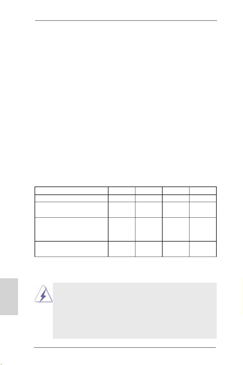
PCIE Slot Congurations
PCIE1 PCIE3 PCIE5 PCIE7
Single Graphics Card x16 N/A N/A N/A
Two Graphics Cards in
x8 N/A x8 N/A
TM
TM
CrossFireX
or SLI
Mode
Three Graphics Cards in
TM
3-Way CrossFireX
or
x8 x8 x8 N/A
TM
3-Way SLI
Mode
Four Graphics Cards in
x8 x8 x8 x4
TM
4-Way CrossFireX
English
1. For better thermal environment, please connect a chassis fan to the
motherboard’s chassis fan connector (CHA_FAN1, CHA_FAN2 or
CHA_FAN3) when using multiple graphics cards.
2. Only PCIE1, PCIE3 and PCIE5 slots support Gen 3 speed. To run
PCI Express in Gen 3 speed, please install an Ivy Bridge CPU. If you
install a Sandy Bridge CPU, the PCI Express will run only at PCI
Express Gen 2 speed.
22
ASRock Z77 Extreme11 Motherboard

Installing an Expansion Card
Step 1. Before installing an expansion card, please make sure that the
power supply is switched off or the power cord is unplugged.
Please read the documentation of the expansion card and make
necessary hardware settings for the card before you start the
installation.
Step 2. Remove the bracket facing the slot that you intend to use. Keep
the screws for later use.
Step 3. Align the card connector with the slot and press rmly until the
card is completely seated on the slot.
Step 4. Fasten the card to the chassis with screws.
English
23
ASRock Z77 Extreme11 Motherboard
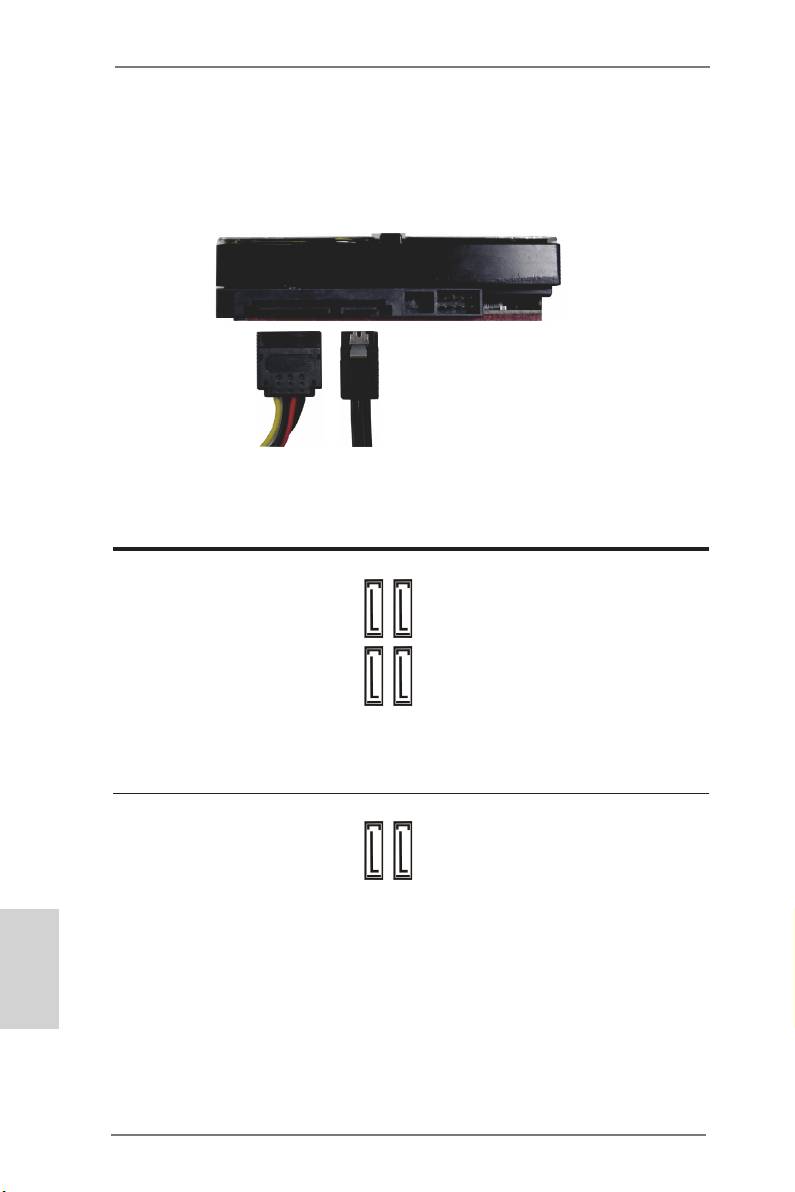
2.5 Installing Serial SATA / SATA2 / SATA3 Hard Disks
STEP 1: Connect the SATA power cable to the hard disk.
STEP 2: Connect one end of the SATA data cable to the hard disk.
STEP 3: Connect the other end of the SATA data cable to the mother-
board’s SAS2 / SATA2 / SATA3 connectors.
Serial ATA2 Connectors
These four Serial ATA2
(SATA2_2_3:
(SATA2) connectors sup-
SATA2_3SATA2_5
SATA2_2SATA2_4
see p.2, No. 14)
port SATA data cables for
(SATA2_4_5:
internal storage devices.
see p.2, No. 15)
The current SATA2 interface
allows up to 3.0 Gb/s data
transfer rate.
Serial ATA3 Connectors
(SATA3_0_1:
SATA3_1
SATA3_0
see p.2, No. 13)
English
These two Serial ATA3 (SATA3) connector supports SATA data cables for
internal storage devices. The current SATA3 interface allows up to 6.0 Gb/
s data transfer rate. If the eSATA3 port on the rear I/O has been connect-
ed, the internal SATA3_1 will not function.
24
ASRock Z77 Extreme11 Motherboard
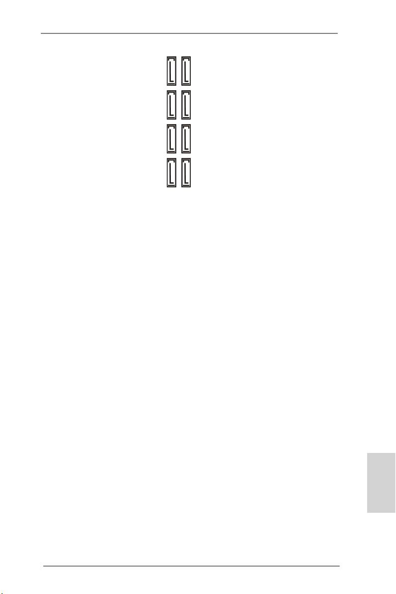
SAS2/Serial ATA3
These eight SAS2/Serial
Connectors
ATA3 (SATA3) connectors
SAS_1SAS_5 SAS_3SAS_7
SAS_0SAS_4 SAS_2SAS_6
(SAS_0_1:
support SAS/SATA data
see p.2, No. 16)
cables for internal storage
(SAS_2_3:
devices. The current SAS2/
see p.2, No. 17)
SATA3 interface allows up to
(SAS_4_5:
6.0 Gb/s data transfer rate.
see p.2, No. 18)
®
We recommend using Intel
(SAS_6_7:
Z77 SATA2 ports instead of
see p.2, No. 19)
SAS ports for your ODDs.
For connecting SAS HDDs,
please contact SAS data
cable dealers.
English
25
ASRock Z77 Extreme11 Motherboard
2.6 Power Connectors
8 5
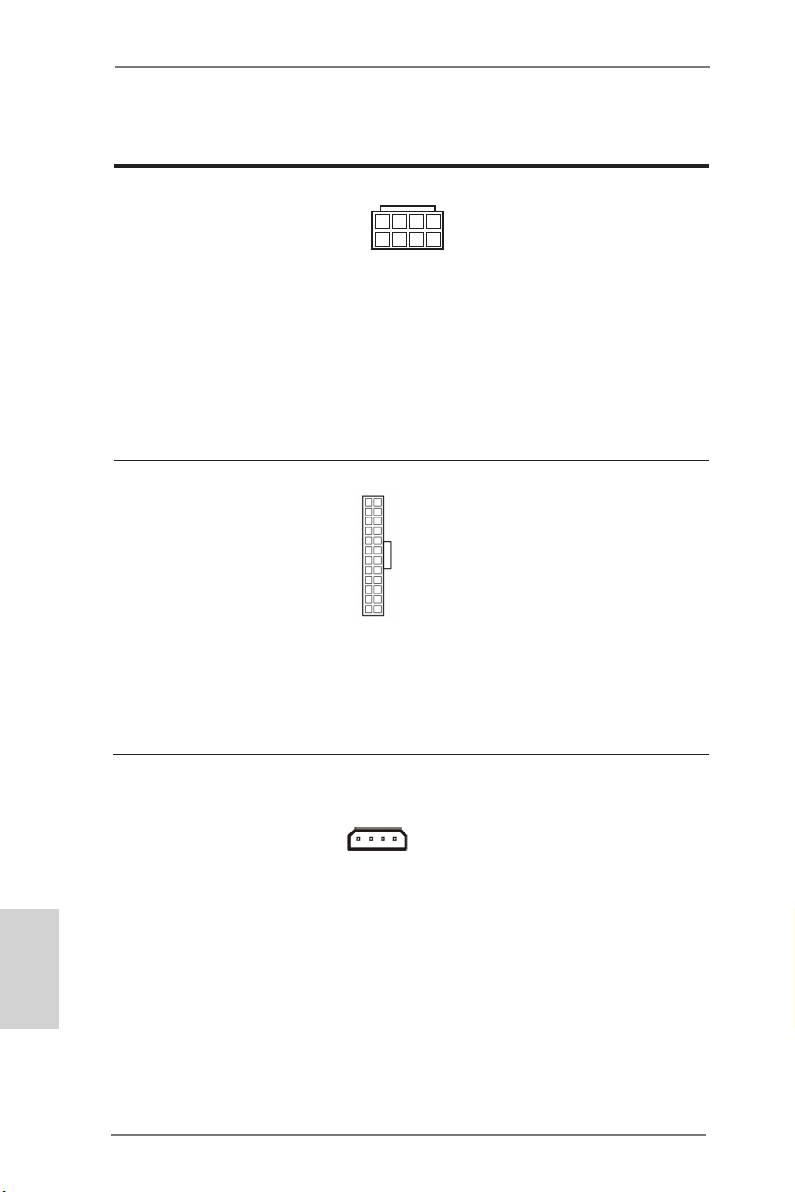
ATX 12V Power Connector
Though this motherboard
(8-pin ATX12V1)
provides 8-pin ATX 12V
(see p.2, No. 1)
4 1
power connector, it can still
work if you adopt a tradi-
tional 4-pin ATX 12V power
supply. To use the 4-pin ATX
power supply, please plug
your power supply along
with Pin 1 and Pin 5.
12
24
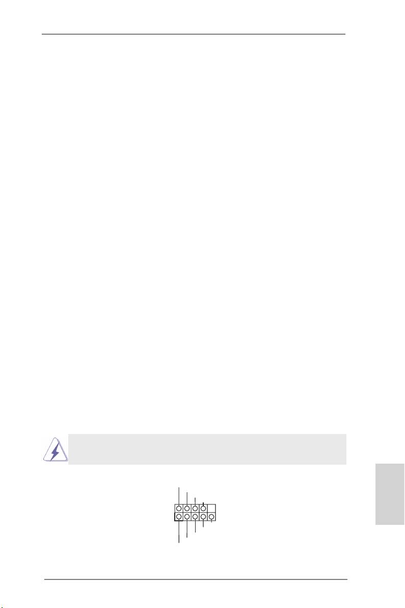
ATX Power Connector
Though this motherboard
(24-pin ATXPWR1)
provides a 24-pin ATX
(see p.2, No. 8)
power connector, it can still
work if you adopt a tradi-
tional 20-pin ATX power
1
13
supply. To use a 20-pin ATX
power supply, please plug
your power supply along Pin
1 and Pin 13.
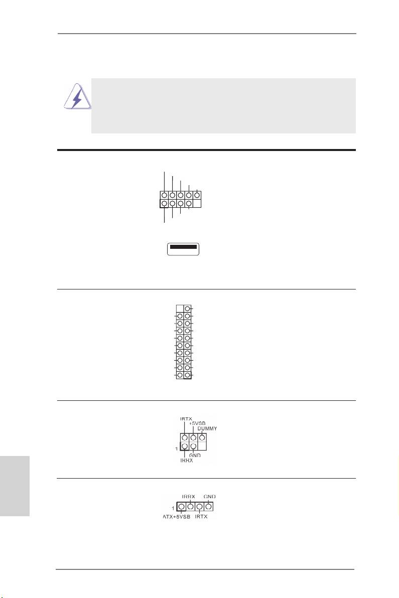
SLI/XFIRE Power Connector
It is not necessary to use
(4-pin SLI/XFIRE_PWR1)
this connector, but please
(see p.2, No. 48)
connect it with a hard disk
SLI/XFIRE_PWR1
power connector when two
graphics cards are plugged
English
to this motherboard.
26
ASRock Z77 Extreme11 Motherboard
2.7 Installing the System Panel
Connect the power switch, reset switch and system status indicator on the
chassis to this header according to the pin assignments below. Note the
positive and negative pins before connecting the cables.
PWRBTN (Power Switch):
Connect to the power switch on the chassis front panel. You may congure
the way to turn off your system using the power switch.
RESET (Reset Switch):
Connect to the reset switch on the chassis front panel. Press the reset
switch to restart the computer if the computer freezes and fails to perform
a normal restart.
PLED (System Power LED):
Connect to the power status indicator on the chassis front panel. The LED
is on when the system is operating. The LED keeps blinking when the sys-
tem is in S1/S3 sleep state. The LED is off when the system is in S4 sleep
state or powered off (S5).
HDLED (Hard Drive Activity LED):
Connect to the hard drive activity LED on the chassis front panel. The LED
is on when the hard drive is reading or writing data.
The front panel design may differ by chassis. A front panel module mainly
consists of power switch, reset switch, power LED, hard drive activity LED,
speaker and etc. When connecting your chassis front panel module to
this header, make sure the wire assignments and the pin assignments are
matched correctly.
The white wires are negative (Connect to - or GND pins),
while the colored ones are positive.
PLED+
System Panel Header
PLED-
PWRBTN#
(9-pin PANEL1)
GND
English
(see p.2, No. 20)
1
GND
R ESET#
GND
HDLED-
HDLED+
27
ASRock Z77 Extreme11 Motherboard
2.8 Onboard Headers and Connectors
Onboard headers and connectors are NOT jumpers. Do NOT
place jumper caps over these headers and connectors. Plac-
ing jumper caps over the headers and connectors will cause
permanent damage to the motherboard!
USB_PWR
USB 2.0 Headers
-B
Besides two default USB 2.0
+B
GND
(9-pin USB2_3)
DUMMY
ports on the I/O panel, there
(see p.2, No. 29)
are three USB 2.0 headers
1
(9-pin USB4_5)
GND
and one USB port on this
+A
(see p.2, No. 30)
-A
USB_PWR
motherboard. Each USB
(9-pin USB6_7)
2.0 header can support two
(see p.2, No. 31)
USB 2.0 ports.
(USB8)
(see p.2, No. 28)
VbusVbus
USB 3.0 Headers
Besides eight default USB
Vbus
IntA_PB_SSRX-
(19-pin USB3_11_12)
IntA_PA_SSRX-
IntA_PB_SSRX+
3.0 ports on the I/O panel,
IntA_PA_SSRX+
GND
(see p.2, No. 9)
GND
IntA_PB_SSTX-
there are two USB 3.0
IntA_PA_SSTX-
IntA_PB_SSTX+
(19-pin USB3_9_10)
IntA_PA_SSTX+
GND
header on this motherboard.
(see p.2, No. 10)
GND
IntA_PB_D-
Each USB 3.0 header can
IntA_PA_D-
IntA_PB_D+
IntA_PA_D+
Dummy
support two USB 2.0 ports.
1
Infrared Module Header
This header supports
(5-pin IR1)
an optional wireless
(see p.2, No. 37)
transmitting and receiving
infrared module.
English
Consumer Infrared
This header can be used
Module Header
to connect the remote
controller receiver.
(4-pin CIR1)
(see p.2, No. 32)
28
ASRock Z77 Extreme11 Motherboard
Front Panel Audio Header
This is an interface for the
(9-pin HD_AUDIO1)
front panel audio cable that
(see p.2, No. 38)
allows convenient connec-
tion and control of audio
devices.
1. High Denition Audio supports Jack Sensing, but the panel wire on
the chassis must support HDA to function correctly. Please follow
the instructions in our manual and chassis manual to install your
system.
2. If you use an AC’97 audio panel, please install it to the front panel
audio header by the steps below:
A. Connect Mic_IN (MIC) to MIC2_L.
B. Connect Audio_R (RIN) to OUT2_R and Audio_L (LIN) to
OUT2_L.
C. Connect Ground (GND) to Ground (GND).
D. MIC_RET and OUT_RET are for HD audio panel only. You don’t
need to connect them for AC’97 audio panel.
E. To activate the front mic.
®
TM
TM
For Windows
8 / 8 64-bit / 7 / 7 64-bit / Vista
/ Vista
64-bit OS:
Go to the “FrontMic” Tab in the Realtek Control panel. Adjust
“Recording Volume”.
Chassis Speaker Header
DUMMY
SPEAKER
Please connect the chassis
(4-pin SPEAKER1)
1
speaker to this header.
+5V
DUMMY
(see p.2, No. 23)
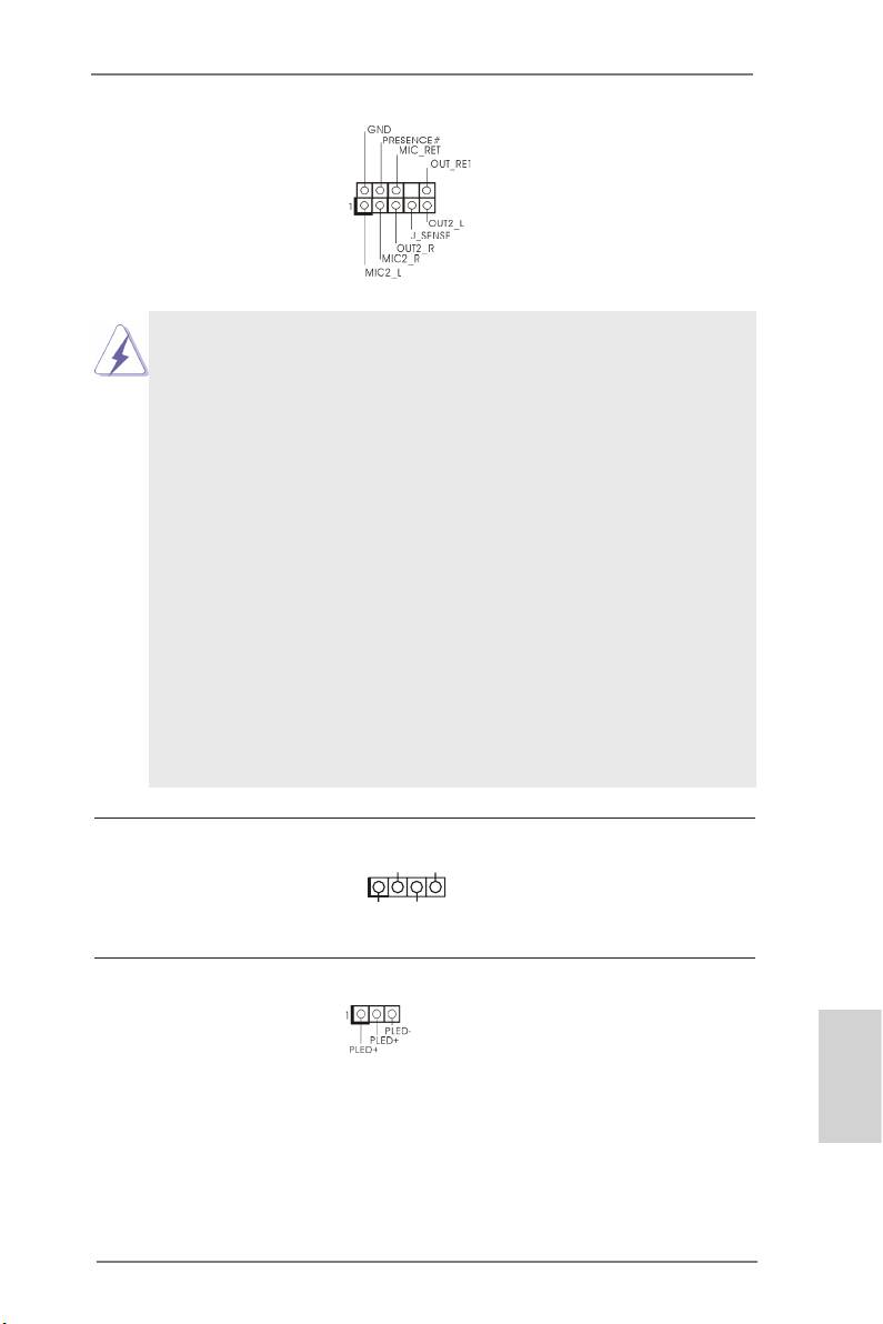
Power LED Header
Please connect the chassis
(3-pin PLED1)
power LED to this header
(see p.2, No. 22)
to
indicate system power
status. The LED is on when
English
the system is operating. The
LED keeps blinking in S1/S3
state. The LED is off in S4
state or S5 state (power off).
29
ASRock Z77 Extreme11 Motherboard
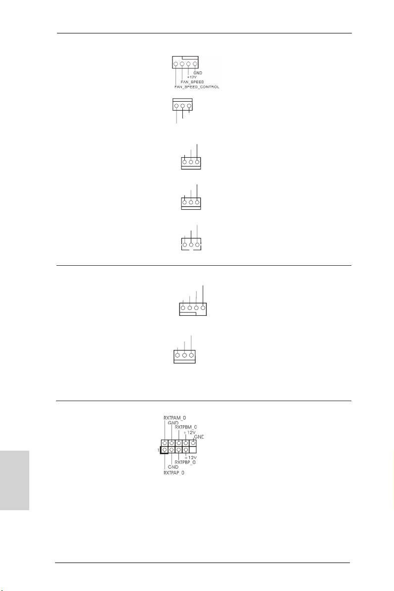
Chassis, Power and SB
Please connect fan cables
Fan Connectors
to the fan connectors and
(4-pin CHA_FAN1)
match the black wire to the
(see p.2, No. 34)
ground pin.
(3-pin CHA_FAN2)
(see p.2, No. 33)
(3-pin CHA_FAN3)
(see p.2, No. 49)
(3-pin PWR_FAN1)
(see p.2, No. 7)
(3-pin SB_FAN1)
(see p.2, No. 11)
English
30
ASRock Z77 Extreme11 Motherboard
GND
+12V
FAN_SPEED
FAN_SPEED
+12V
GND
FAN_SPEED
+12V
GND
FAN_SPEED
+12V
GND
CPU Fan Connectors
Though this motherboard
(4-pin CPU_FAN1)
provides a 4-Pin CPU fan
(see p.2, No. 4)
(Quiet Fan) connector, 3-Pin
CPU fans can still work suc-
(3-pin CPU_FAN2)
cessfully even without fan
(see p.2, No. 3)
speed control. If you plan to
connect a 3-Pin CPU fan,
please connect it to Pin 1-3.
IEEE 1394 Header
Besides one default IEEE
(9-pin FRONT_1394)
1394 port on the I/O panel,
(see p.2, No. 35)
there is
one IEEE 1394
header on this motherboard.
This IEEE 1394 header can
support one IEEE 1394 port.
FAN_SPEED
+12V
GND
FAN_SPEED_CONTROL
FAN_SPEED
+12V
GND
1234
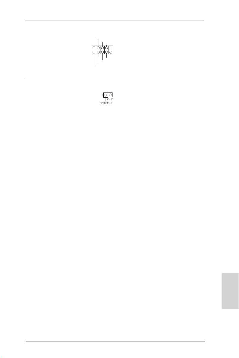
RRXD1
Serial Port Header
DDTR#1
This COM1 header supports
DDSR#1
CCTS#1
(9-pin COM1)
a serial port module.
(see p.2, No. 36)
1
RRI#1
RRTS#1
GND
TTXD1
DDCD#1
HDMI_SPDIF Header
This header provides SPDIF
(2-pin HDMI_SPDIF1)
audio output to HDMI VGA
(see p.2, No. 39)
cards, allowing the system
to connect HDMI Digital
TV/projector/LCD devices.
Please connect the HDMI_
SPDIF connector of a HDMI
VGA card to this header.
English
31
ASRock Z77 Extreme11 Motherboard
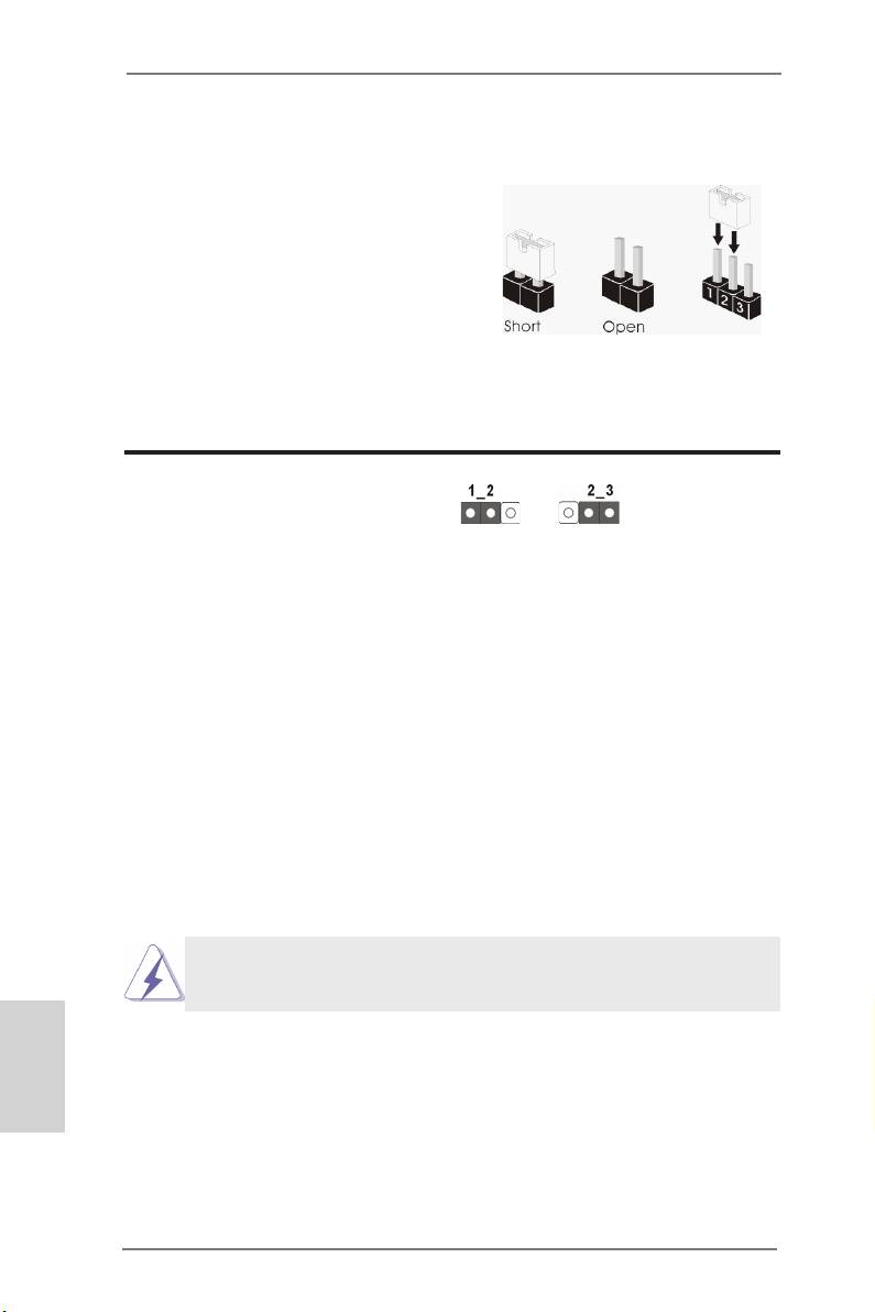
2.9 Jumpers Setup
The illustration shows how jumpers are
setup. When the jumper cap is placed
on the pins, the jumper is “Short”. If
no jumper cap is placed on the pins,
the jumper is “Open”. The illustration
shows a 3-pin jumper whose pin1 and
pin2 are “Short” when a jumper cap is
placed on these 2 pins.
Clear CMOS Jumper
(CLRCMOS1)
Clear CMOSDefault
(see p.2, No. 24)
CLRCMOS1 allows you to clear the data in CMOS. To clear and reset
the system parameters to default setup, please turn off the computer and
unplug the power cord from the power supply. After waiting for 15 seconds,
use a jumper cap to short pin2 and pin3 on CLRCMOS1 for 5 seconds.
However, please do not clear the CMOS right after you update the BIOS.
If you need to clear the CMOS when you just nish updating the BIOS,
you must boot up the system rst, and then shut it down before you do the
clear-CMOS action. Please be noted that the password, date, time, user
default prole, 1394 GUID and MAC address will be cleared only if the
CMOS battery is removed.
The Clear CMOS Switch has the same function as the Clear CMOS
jumper.
English
32
ASRock Z77 Extreme11 Motherboard
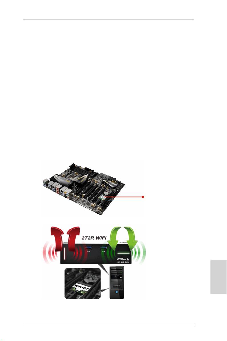
2.10 WiFi + BT Module and ASRock Wi-SB Box
WiFi + BT Module
This motherboard comes with an exclusive WiFi 802.11 a/b/g/n + BT v4.0
module that offers support for WiFi 802.11 a/b/g/n connectivity standards
and Bluetooth v4.0. WiFi + BT module is an easy-to-use wireless local
area network (WLAN) adapter to support WiFi + BT. Bluetooth v4.0 stan-
dard features Smart Ready technology that adds a whole new class of
functionality into the mobile devices including Apple’s most recent iPhone
4S. BT 4.0 also includes Low Energy Technology and ensures extraordi-
nary low power consumption for PCs. The 2T2R WiFi solution sets a WiFi
high speed standard and offers max link rate up to 300Mbps. Compared to
other 1T1R WiFi motherboards with 150Mbps, ASRock’s 2T2R WiFi solu-
tion drives up to 2X faster.
* The transmission speed may vary according to the environment.
®
* The WiFi + BT module is supported under Windows
8 / 8 64-bit / 7 / 7 64-bit only.
WiFi + BT Module
English
33
ASRock Z77 Extreme11 Motherboard
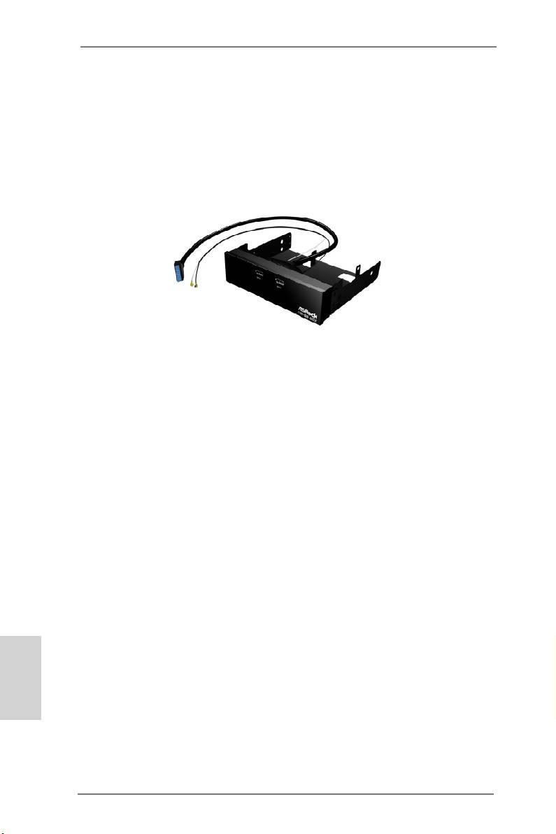
ASRock Wi-SB Box
Thanks to the excellent placement of antennas, ASRock Wi-SB Box comes with
two invisible antennas (placed in a vertical/horizontal position), hidden inside the
front panel that provides the most stable and unrestricted-direction wireless network
coverage, optimized for maximum broadband network. Additionally, it provides two
Front USB 3.0 ports for easier USB 3.0 device access and 1 rack for SSD place-
ment.
ASRock Wi-SB Box
English
34
ASRock Z77 Extreme11 Motherboard
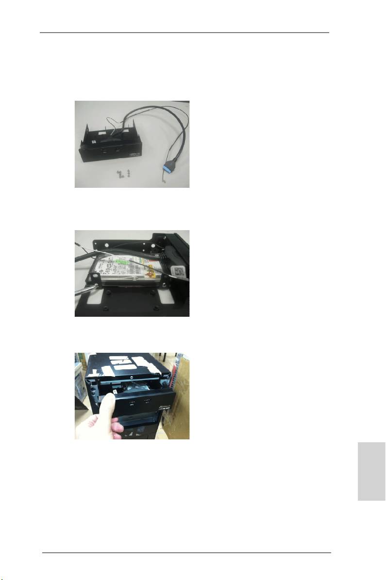
Installing the WiFi + BT Module and ASRock Wi-SB Box
Step 1. Prepare the bundled ASRock Wi-SB Box and screws.
Step 2. If you have 2.5” HDD/SSDs, you may insert up to two and secure them in
ASRock Wi-SB Box with screws.
Step 3. Install ASRock Wi-SB Box into the drive bay of the chassis.
English
35
ASRock Z77 Extreme11 Motherboard
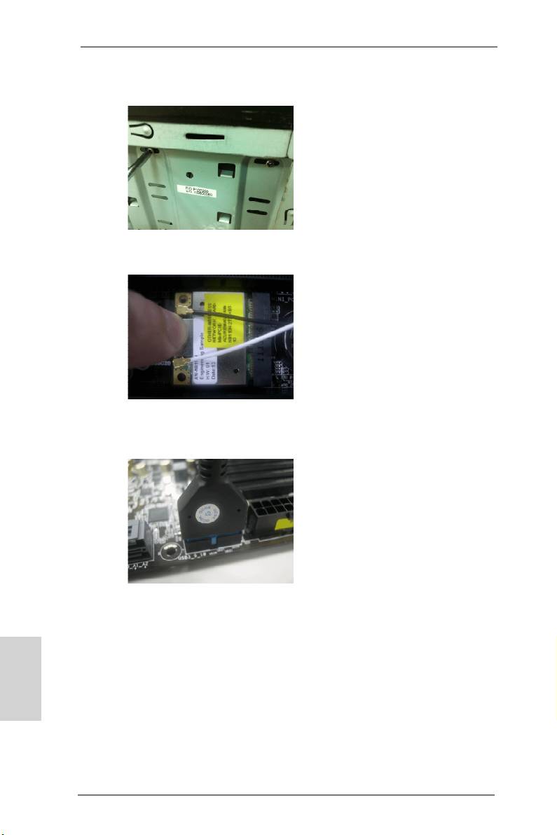
Step 4. Screw ASRock Wi-SB Box to the drive bay with screws.
Step 5. Attach the cords to the WiFi + BT module on your motherboard.
Step 6. Plug the Front USB 3.0 cable into the USB 3.0 header on the mother-
board.
English
36
ASRock Z77 Extreme11 Motherboard

2.11 Operating System Setup
®
®
This motherboard supports various Microsoft
Windows
operating sys-
TM
TM
tems: 8 / 8 64-bit / 7 / 7 64-bit / Vista
/ Vista
64-bit. Because mother-
board settings and hardware options vary, use the setup procedures in this
chapter for general reference only. Refer your OS documentation for more
information.
English
37
ASRock Z77 Extreme11 Motherboard

®
TM
2.11.1 Installing Windows
8 / 8 64-bit / 7 / 7 64-bit / Vista
/
TM
Vista
64-bit without RAID
Using AHCI Mode
STEP 1: Set Up UEFI.
Press <F2> or <Delete> at system POST. Set AHCI Mode in UEFI Setup
Utility > Advanced > Storage Conguration > SATA Mode.
®
TM
TM
STEP 2: Install Windows
8 / 8 64-bit / 7 / 7 64-bit / Vista
/ Vista
64-
bit on your system.
Using IDE Mode
STEP 1: Set Up UEFI.
Press <F2> or <Delete> at system POST. Set IDE Mode in UEFI Setup
Utility > Advanced > Storage Conguration > SATA Mode.
®
TM
TM
STEP 2: Install Windows
8 / 8 64-bit / 7 / 7 64-bit / Vista
/ Vista
64-
bit on your system.
English
38
ASRock Z77 Extreme11 Motherboard
®
TM
2.11.2 Installing Windows
8 64-bit / 7 64-bit / Vista
64-bit on
a HDD Larger than 2 terabytes (2TB) without RAID
®
This motherboard adopts UEFI BIOS that allows Windows
OS to be
®
installed on a large size HDD (>2TB). Please make sure to use Windows
TM
Vista
64-bit (with SP2 or above), 7 64-bit or 8 64-bit and follow the
procedures below to install the operating system.
Using AHCI Mode
STEP 1: Set Up UEFI.
Press <F2> or <Delete> at system POST. Set AHCI Mode in UEFI Setup
Utility > Advanced > Storage Conguration > SATA Mode.
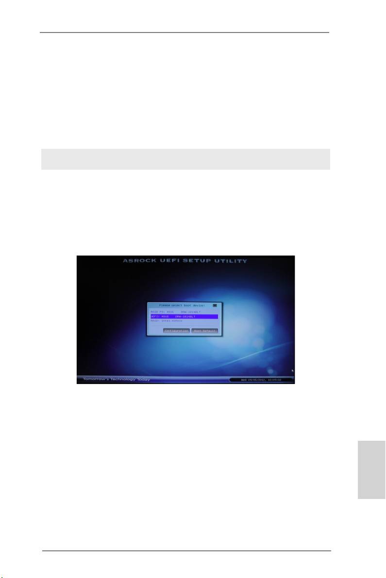
STEP 2: Press <F11> to launch boot menu at system POST and choose
the item “UEFI:<Optical disk drive>“ to boot.
®
STEP 3: Start Windows
installation.
English
39
ASRock Z77 Extreme11 Motherboard

®
TM
2.11.3 Installing Windows
8 / 8 64-bit / 7 / 7 64-bit / Vista
/
TM
Vista
64-bit with RAID
STEP 1: Set Up UEFI.
Press <F2> or <Delete> at system POST. Set RAID Mode in UEFI Setup
Utility > Advanced > Storage Conguration > SATA Mode.
STEP 2: Use “RAID Installation Guide” to set the RAID conguration.
Before you start to configure RAID, you need to check the installation
guide in the Support CD for proper configuration. Please refer to the
document in the Support CD, “Guide to SATA Hard Disks Installation and
RAID Conguration”, which is located in the folder at the following path:
.. \ RAID Installation Guide
®
TM
TM
STEP 3: Install Windows
8 / 8 64-bit / 7 / 7 64-bit / Vista
/ Vista
64-
bit on your system.
English
40
ASRock Z77 Extreme11 Motherboard
