Ridgid SeeSnake LT1000: instruction
Class: Power tools
Type:
Manual for Ridgid SeeSnake LT1000
EN
P. 1
FR
P. 19
ES
P. 37
DE
P. 57
NL
P. 77
IT
P. 97
PT
P. 117
SV
P. 137
DA
P. 155
NO
P. 173
FI
P. 191
PL
P. 209
CZ
P. 229
SK
P. 247
RO
P. 267
HU
P. 285
EL
P. 303
HR
P. 323
SL
P. 341
SR
P. 359
RU
P. 377
TR
P. 399
RIDGE TOOL COMPANY
Tools For The Professional
TM
SeeSnake®
LT1000

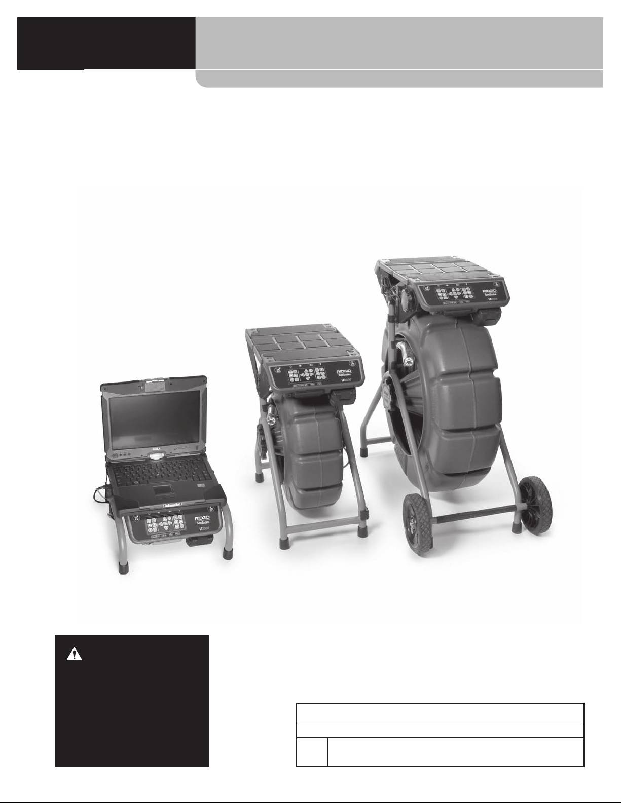
SeeSnake® LT1000
SeeSnake® LT1000
WARNING!
Read this Operator’s Manual
carefully before using this
tool. Failure to understand
and follow the contents of
SeeSnake® LT1000
this manual may result in
Record Serial Number below and retain product serial number which is located on nameplate.
electrical shock, fire and/or
Serial
serious personal injury.
No.

SeeSnake® LT1000
Table of Contents
Recording Form for Machine Serial Number ......................................................................................................................................................1
Safety Symbols
......................................................................................................................................................................................................................3
General Safety Rules
..........................................................................................................................................................................................................3
Work Area Safety
...............................................................................................................................................................................................................3
Electrical Safety
..................................................................................................................................................................................................................3
Personal Safety
..................................................................................................................................................................................................................3
Equipment Use and Care
..............................................................................................................................................................................................4
Battery Tool Use And Care
............................................................................................................................................................................................4
Service
...................................................................................................................................................................................................................................4
Specific Safety Information
...........................................................................................................................................................................................5
LT1000 Safety
......................................................................................................................................................................................................................5
Description, Specifications And Standard Equipment
.................................................................................................................................5
Description
..........................................................................................................................................................................................................................5
Specifications
.....................................................................................................................................................................................................................6
Laptop System Requirements
....................................................................................................................................................................................6
Standard Equipment.......................................................................................................................................................................................................6
Optional Equipment
.......................................................................................................................................................................................................6
LT1000 Components
..........................................................................................................................................................................................................6
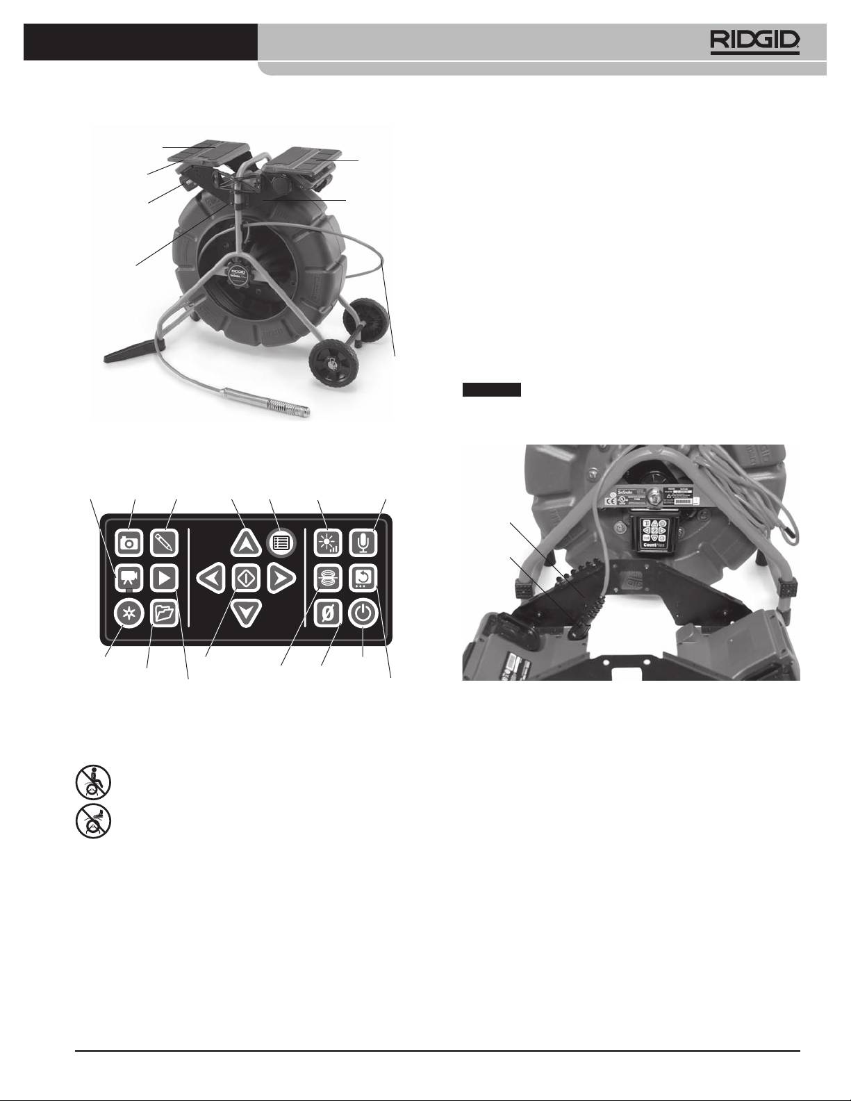
Icons
.............................................................................................................................................................................................................................................7
Assembly
..................................................................................................................................................................................................................................7
Mounting the LT1000
.....................................................................................................................................................................................................7
Mounting the LT1000 to the SeeSnake Mini Reel..............................................................................................................................................7
Mounting the LT1000 to the SeeSnake Standard Reel....................................................................................................................................8
Installing the Stabilizers
.............................................................................................................................................................................................. 10
LT1000 Mini
..................................................................................................................................................................................................................... 11
Preparing the Laptop
...................................................................................................................................................................................................11
Pre-Operation Inspection
............................................................................................................................................................................................ 11
Work Area and Equipment Set Up
.......................................................................................................................................................................... 12
LT1000 Placement
......................................................................................................................................................................................................... 12
Mounting the Laptop
.................................................................................................................................................................................................. 12
Connecting the LT1000
............................................................................................................................................................................................... 13
Powering the SeeSnake LT1000
.............................................................................................................................................................................. 13
LT1000 Controls
................................................................................................................................................................................................................. 14
Keypad Controls
............................................................................................................................................................................................................. 14
About HQ Software
...................................................................................................................................................................................................... 15
Operating Instructions
.................................................................................................................................................................................................. 15
Starting Up
....................................................................................................................................................................................................................... 15
Inspecting the Line
....................................................................................................................................................................................................... 15
Brightness Adjustment
.......................................................................................................................................................................................... 15
Image Rotation
........................................................................................................................................................................................................... 15
CountPlus Control
..................................................................................................................................................................................................... 15
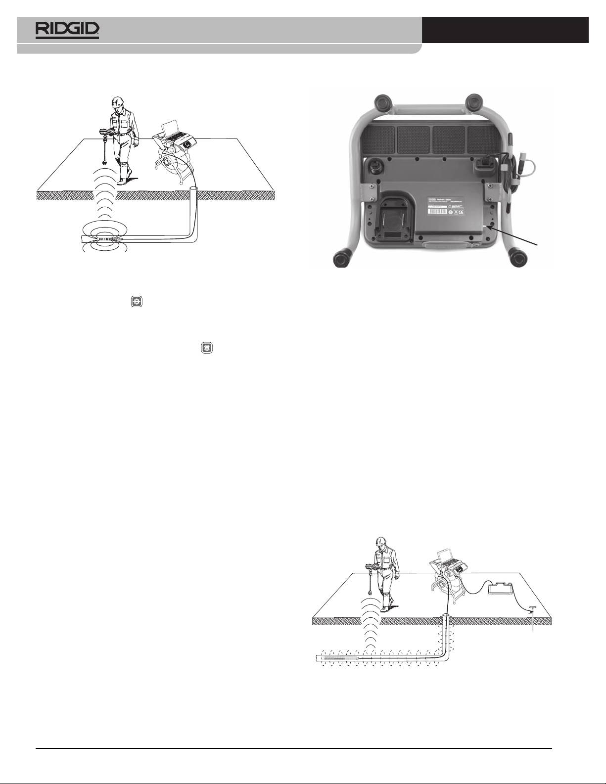
Locating The Camera Using The Sonde
.............................................................................................................................................................. 15
Line Tracing The SeeSnake Pushrod
.................................................................................................................................................................... 16
Maintenance Instructions............................................................................................................................................................................................ 17
Cleaning
............................................................................................................................................................................................................................. 17
Accessories
........................................................................................................................................................................................................................... 17
Transport And Storage
.................................................................................................................................................................................................. 17
Service And Repair
........................................................................................................................................................................................................... 17
Disposal
.................................................................................................................................................................................................................................. 17
Battery Disposal
................................................................................................................................................................................................................ 17
Troubleshooting................................................................................................................................................................................................................18
Lifetime Warranty
........................................................................................................................................................................................... Back Cover
*Original Instructions - English
2
SeeSnake® LT1000
Safety Symbols
In this operator’s manual and on the product, safety symbols and signal words are used to communicate important
safety information. This section is provided to improve understanding of these signal words and symbols.
This is the safety alert symbol. It is used to alert you to potential personal injury hazards. Obey all safety messages that
follow this symbol to avoid possible injury or death.
DANGER
DANGER indicates a hazardous situation which, if not avoided, will result in death or serious injury.
WARNING
WARNING indicates a hazardous situation which, if not avoided, could result in death or serious injury.
CAUTION
CAUTION indicates a hazardous situation which, if not avoided, could result in minor or moderate injury.
NOTICE
NOTICE indicates information that relates to the protection of property.
This symbol means read the operator’s manual carefully before using the equipment. The operator’s manual contains
important information on the safe and proper operation of the equipment.
This symbol means always wear safety glasses with side shields or goggles when handling or using this equipment to
reduce the risk of eye injury.
This symbol indicates the risk of electrical shock.
EU Model
General Safety Rules
• Double-insulatedtoolsareequippedwithanon-
WARNING
polarised2pinplug. Double insulation eliminates
Read all safety warnings and instructions. Failure to
the need for the three-wire grounded power cord
follow the warnings and instructions may result in
and grounded supply system.
electric shock, fire and/or serious injury.
• Avoid body contact with earthed orgrounded
SAVE ALL WARNINGS AND INSTRUCTIONS
surfaces such as pipes, radiators, ranges and re-
FOR FUTURE REFERENCE!
frigerators. There is an increased risk of electrical
shock if your body is earthed or grounded.
Work Area Safety
• Donotexposeequipmenttorainorwetcondi-
• Keepworkareacleanandwelllit.Cluttered or dark
tions.Water entering equipment will increase the
areas invite accidents.
risk of electrical shock.
• Do not operate equipment in explosive atmo-
• Donotabuse thecord.Never usethecord for
spheres, such as in the presence of flammable liq-
carrying,pullingorunpluggingtheequipment.
uids, gases or dust. Equipment can create sparks
Keepcordawayfromheat,oil,sharpedgesor
which may ignite the dust or fumes.
moving parts. Damaged or entangled cords in-
• Keep children and by-standers away while op-
crease the risk of electric shock.
eratingequipment.Distractions can cause you to
• Ifoperatingequipmentinadamplocationisun-
lose control.
avoidable, use a ground fault circuit interrupter
(GFCI)protectedsupply. Use of a GFCI reduces the
Electrical Safety
risk of electric shock.
US Model
• Keepall electrical connectionsdry and o the
• Double-insulatedtoolsareequippedwithapo-
ground.Donottouchequipmentorplugswith
larizedplug (oneblade wider than theother).
wethands.This reduces the risk of electrical shock.
Thisplugwilltinapolarizedoutletonlyone
way.Iftheplugdoesnottfullyinthesocket,
Personal Safety
reversetheplug.Ifitstilldoesnott,contacta
• Stay alert, watch what you are doing and use
qualiedelectriciantoinstallapolarizedoutlet.
commonsensewhenoperatingequipment.Do
Donotchangethepluginanyway.
notuseequipmentwhileyouaretiredorunder
theinuenceofdrugs,alcoholormedication.A
3

SeeSnake® LT1000
moment of inattention while operating equipment
• Keephandles dry andclean; free fromoil and
may result in serious personal injury.
grease.Allows for better control of the equipment.
• Usepersonalprotectiveequipment.Alwayswear
Battery Tool Use And Care
eyeprotection.Protective equipment such as dust
mask, non-skid safety shoes, hard hat, or hearing
• Rechargeonlywiththechargerspeciedbythe
protection used for appropriate conditions will re-
manufacturer. A charger that is suitable for one
duce personal injuries.
type of battery pack may create a risk of fire when
used with another battery pack.
• Donotoverreach.Keepproperfootingandbal-
anceatalltimes.This enables better control of the
• Useequipmentonlywithspecicallydesignated
equipment in unexpected situations.
batterypacks.Use of any other battery packs may
create a risk of injury and fire.
• Dressproperly.Donotwearlooseclothingorjew-
elry. Keep your hair, clothing, and gloves away
• Do notprobe battery with conductiveobjects.
frommovingparts.Loose clothes, jewelry, or long
When battery pack is not inuse, keep it away
hair can be caught in moving parts.
fromothermetalobjects,likepaperclips,coins,
keys,nails,screwsorothersmallmetalobjects
Equipment Use and Care
that can make a connection from one terminal
toanother. Shorting the battery terminals together
• Donotforceequipment.Usethecorrectequip-
may cause burns or a fire.
mentforyourapplication.The correct equipment
will do the job better and safer on the job for which
• Under abusiveconditions,liquid maybe eject-
it is designed.
ed from the battery; avoid contact. If contact
accidentally occurs, ush with water. If liquid
• Donotuseequipmentiftheswitchdoesnotturn
contacts eyes, additionally seek medical help.
itONandOFF. Any equipment that cannot be con-
Liquid ejected from the battery may cause irritation
trolled with the switch is dangerous and must be
or burns.
repaired.
• Useandstorebatteriesandchargersindry,ap-
• Disconnecttheplugfromthepowersourceand/
propriate temperature areas. Extreme tempera-
or the battery pack from the equipment before
tures and moisture can damage batteries and result
makinganyadjustments,changingaccessories,
in leakage, electrical shock, fire or burns. See charger
orstoring. Such preventive safety measures reduce
manual for more information.
the risk of injury.
• Donotcoverchargerwhileinuse.Properventi-
• Storeidleequipmentoutofthereachofchildren
lationisrequiredforcorrectoperation. Covering
and do not allow persons unfamiliar with the
charger in use could result in fire.
equipment or these instructions to operate the
equipment. Equipment can be dangerous in the
• Properly dispose of batteries. Expo sure to high
hands of untrained users.
temperatures can cause the batteries to explode,
so do not dispose of in a fire. Some countries have
• Maintain equipment. Check for misalignment or
regulations concerning battery disposal. Please fol-
binding of moving parts, missing parts, breakage
low all applicable regulations.
of parts and any other condition that may affect
the equipment’s operation. If damaged, have the
Service
equipment repaired before use. Many accidents are
caused by poorly maintained equipment.
• Have your equipment serviced by a qualied
repair person using only identical replacement
• Use the equipment and accessories in accor-
parts. This will ensure that the safety of the equip-
dance with these instructions, taking into ac-
ment is maintained.
counttheworkingconditionsandtheworktobe
performed. Use of the equipment for operations
• Remove the batteries and refer servicing to qualified
different from those intended could result in a haz-
service personnel under any of the following condi-
ardous situation.
tions:
• Useonlyaccessoriesthatarerecommendedby
• If liquid has been spilled or objects have fallen
themanufacturerforyourequipment. Accesso-
into product;
ries that may be suitable for one piece of equipment
• If product does not operate normally by follow-
may become hazardous when used with other
ing the operating instructions;
equipment.
4

SeeSnake® LT1000
• If the product has been dropped or damaged in
• Donotusewhereadangerofhighvoltagecon-
any way; or,
tactispresent.The equipment is not designed to
• When the product exhibits a distinct change in
provide high voltage protection and isolation.
performance.
• Read and understand this operator’s manual,
thereeloperators’manualandtheinstructions
Specific Safety Information
foranyotherequipmentinuseandallwarnings
beforeoperatingtheLT1000. Failure to follow all
WARNING
instruction may result in property damage and/or
This section contains important safety information
serious personal injury.
that is specific to this equipment.
• Alwaysuseappropriatepersonalprotectiveequip-
Read these precautions carefully before using the
ment while handling and using equipment in
LT1000 to reduce the risk of electrical shock or other
drains. Drains may contain chemicals, bacteria and
serious personal injury.
other substances that may be toxic, infectious, cause
SAVE THESE INSTRUCTIONS!
burns or other issues. Appropriate personal protec-
tive equipment always includes safety glasses, and
Keep this manual with the machine for use by the op-
may include equipment such as drain cleaning
erator.
gloves or mitts, latex or rubber gloves, face shields,
goggles, protective clothing, respirators and steel-
The EC declaration of conformity (890-011-320.10) will
toed footwear.
accompany this manual as a separate booklet when re-
quired.
• If using drain cleaning equipment at the same
time as using drain inspection equipment, only
If you have any question concerning this RIDGID® prod-
wearRIDGIDDrainCleaningGloves.Never grasp
uct:
the rotating drain cleaning cable with anything else,
– Contact SeeSnake HQ Support Department at
includ ing other gloves or a rag. They can become
HQSupport@seesnake.com for questions relating to
wrapped around the cable, causing hand injuries.
HQ.
Only wear latex or rubber gloves under RIDGID Drain
– Contact your local RIDGID® distributor.
Clean er Gloves. Do not use damaged drain cleaning
gloves.
– Visit www.RIDGID.com or www.RIDGID.eu to find your
local RIDGID contact point.
• Practice good hygiene. Use hot, soapy water to
– Contact RIDGID Technical Services Department at
wash hands and other exposed body parts exposed
rtctechservices@emerson.com, or in the U.S. and
to drain contents after handling or using drain in-
Cana da call (800) 519-3456.
spection equipment. Do not eat or smoke while
operating or handling drain inspection equipment.
LT1000 Safety
This will help prevent contamination with toxic or
• An improperly grounded electrical outlet can
infectious material.
cause electrical shock and or severely damage
equipment. Always check work area for a prop-
Description, Specifications And
erly grounded electrical outlet. Presence of a three
Standard Equipment
prong or GFCI outlet does not insure that the outlet
is properly grounded. If in doubt, have the outlet in-
Description
spected by a licensed electrician.
The SeeSnake® LT1000 is a convenient interface and
• Useonlyabatteryortheincludedisolatedpower
platform which allows any standard laptop to serve
supplytopowertheLT1000.Usebatteriesoran
as a SeeSnake Inspection monitor, and can be used to
isolatedpowersupplywithanylaptopusedwith
automatically capture photos, motion clips and sound
theLT1000.This minimizes the risk of electrical haz-
recordings from a SeeSnake Pipe Inspection System. It
ards from moisture or faulty electrical outlets.
provides a convenient interface to SeeSnake HQ report
• Do not operate this equipment if operator or
generating and video managing software to make cre-
machineisstandinginwater.Operating machine
ating and managing customer reports quick and easy.
while in water increases the risk of electrical shock.
The LT1000 also provides a robust laptop platform to
• TheLT1000isnotwaterproof.Itisdust-resistant
which the laptop can be rapidly secured and connect-
and splash-resistant. Do not expose the equip-
ed, and easily removed when needed. Two platform
ment to water or rain. This increases the risk of elec-
wings may be used to increase the work platform area.
trical shock.
5
SeeSnake® LT1000
The individual platform wings may be separately fold-
• Optional:-DVDburnerforcreatingDVDreportsIn-
ed in, to provide platform support across the center
ternet connection for emailing reports, uploading
of the SeeSnake, or they may be folded out to extend
reports to Ridgid Connect, etc.
platform support at either end of the LT1000.
Recommended minimum screen resolution: 1024 x
768
Specifications
LT1000
Standard Equipment
Weight........................................... 6.4 lbs. / 2,9 kg w/o Battery
• LT1000
7.35 lbs. / 3,3 kg with Battery
• 100-220VACto15VDCPowerConverterandSup-
(without Laptop)
ply
Dimensions:
• Operator’sManual
Length, platform wings
• InstructionalDVD
closed.......................................... 20.6” / 52,3 cm
• Stabilizers(4)
Length, platform wings
• USBCable
open............................................ 21.7” / 55,1 cm
Optional Equipment
Width, Standard..................... 12.8” / 32,5 cm
Other auxiliary equipment used with the SeeSnake
Width, Shipping..................... 11.9” / 30,2 cm
LT1000 may include:
Height......................................... 6.5” / 16,5 cm
• Rechargeablebattery
Power Source............................ 100 - 240V AC / 50 - 60Hz, AC or
18V DC Rechargeable Battery
• ARIDGID®locator/receiver(suchastheSR-20,the
SR-60, the Scout® or the NaviTrack® II)
Battery Type............................... 18V Li-Ion, 2.2 Ah / 2,2 Ah
• ARIDGID®transmitter(suchastheST-510,the
Power Rating 14 - 16V DC 40W
ST-305, ST-33Q, the NaviTrack® Brick or the
Operating Environment:
NaviTrack® 10-watt transmitter)
Temperature............................ -4°F to 167°F / -20°C to 75°C
• TheCountPlus Cable Counter cable-measurement
Humidity.................................... 5% to 95% RH
system, normally built in to SeeSnake Pipe In spec-
tion Systems
Altitude....................................... 13,120 feet / 4.000 meters
The LT1000 is protected under U.S. and international
LT1000 Mini
patents.
Weight........................................... 6.1 lbs. / 2,78 kg w/o Battery
7.4 lbs. / 3,4 kg with Battery
(without Laptop)
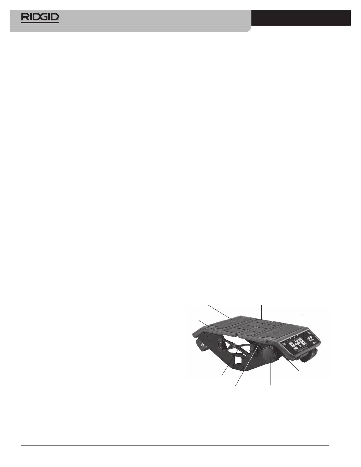
LT1000 Components
Dimensions:
Laptop Platform
Folding Platform Wing
Length........................................ 13.6” / 34,5 cm
Keypad
Width.......................................... 11.9” / 30,2 cm
Side Plate
Height......................................... 6.5” / 16,5 cm
Laptop System Requirements
• Windows® 7, Windows Vista® (SP2), Windows XP
(SP3) (Windows 7 is recommended)
• Intel®Pentium®orAMDAthlon™1.8GHz/1,8GHz
(2.4GHz / 2,4GHz or higher recommended) or Intel
Transmitter
Core™2Duo2.4GHz/2,4GHz
Clip-on
USB Cord
Terminal
• GBsystemmemory(2GBrecommended)
Retaining Cord
Capstan
• DirectX® 9 or 10 compatible graphics card with
128 MB (256 MB or higher recommended)
Figure 1 – Platform Wings Folded In
• DirectX®9orhighercompatiblesoundcard
• 30GBofdiskspace
• CD-ROMdriveorInternetconnectiontoinstallsoft-
ware
• 1USB2.0port
6
SeeSnake® LT1000
PlatformWingsExtended
side of the LT1000 while for the Mini’s narrower frame,
Laptop Platform
the curved portions of the brackets point inward.
Platform
Platform
Wings
Mounting the LT1000 to the SeeSnake
Wings
Mini Reel
Side Plate
18V Battery
1. Remove the two mounting brackets from the sides
of the LT1000.
2. Before mounting the LT1000 on the frame, lead the
Mounting
SeeSnake System Cable up to the SeeSnake System
Brackets
Connector. The SeeSnake System Cable has a guide
ridge molded into the top of the cable connector.
With the guide ridge aligned with the guide pin at
the top of the receptacle, insert the System Cable
into the System Connector firmly and turn the lock-
SeeSnake
ing sleeve clockwise to tighten it in position.
System
Cable
NOTICE
When connecting/disconnecting the SeeSnake
system cable, turn only the locking sleeve. To prevent dam-
age, do not bend or twist the connector or cable.
Figure 2 – LT1000 Components
Video
Photo
Photo
Arrow
Menu
Brightness
Microphone
Key
Key
TagKey
Keys
Key
Key
MuteKey
Guide
Locking
Sleeve
Autolog
Select
Power
Key
Job
Key
Sonde
Zero
Key
Management
Playback
Key
Key
Image Flip
Key
Key
Key
Figure 4 – Connecting System Cable Before Mounting
Figure3–LT1000Keypad
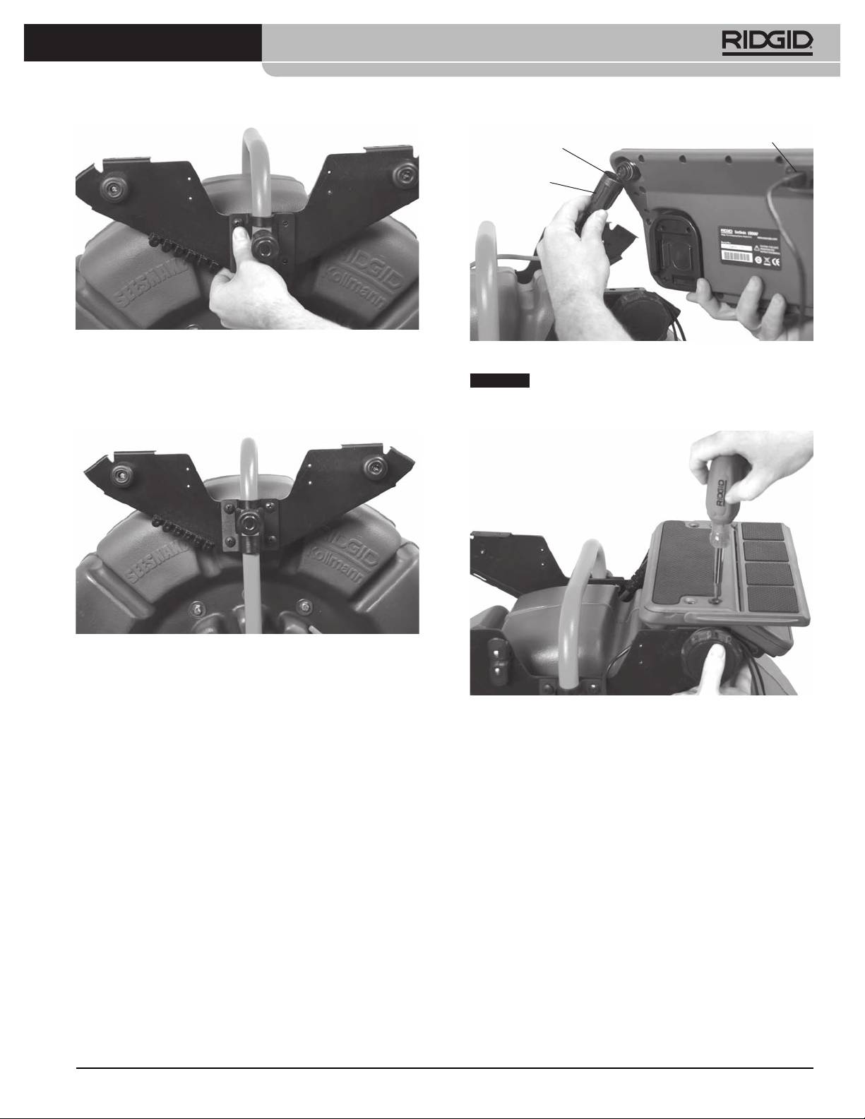
3. The Mini SeeSnake has the curved portions of the
mounting brackets face inward. Position the LT1000
Icons
with the opening in the side plate seated over the
“foot” on the SeeSnake Reel frame and hold it in
Do not sit on the LT1000.
its approximate position while starting the attach-
ing machine screws on one side of the LT1000. The
Do not stand on the LT1000.
SeeSnake may be laid on its back for easier installa-
tion of the front side panel.
Assembly
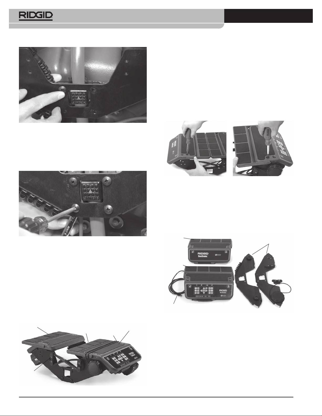
Mounting the LT1000
The LT1000 mounts to any Standard or Mini SeeSnake
reel quickly and easily. Assembly requires a Phillips
7
head screwdriver and a
/
16
” / 11 mm box wrench. The
mounting sequence for the SeeSnake Mini is different
than the sequence for the SeeSnake Standard.
Note that for the Standard SeeSnake reel, the curved por-
tions of the mounting brackets are oriented to the out-
7
SeeSnake® LT1000
Mounting the LT1000 to the SeeSnake
Standard Reel
Mounting the LT1000 on a Standard SeeSnake reel re-
quires removing the two laptop platform surfaces and
the right-hand USB cord wrap from the LT1000 frame.
1. With a Phillips screwdriver, remove two screws from
the USB cable wrap on the right side (the one which
holds down the USB cable where it enters the LT1000).
Unwind the USB cable from the cord wraps.
2. Remove the four screws from each platform half.
Figure5–FirstMachineScrew
4. With one side loosely bolted into position, align the
opposite side and start the four machine screws on
the opposite side. The screw-heads should be on
the outer face of the LT1000 and the nuts on the
inner face.
Figure8–RemovingthePlatformScrews(SeeSnake
Standard)
3. Lift off the two platform halves and set them to one
side close to the SeeSnake frame. Save all screws
carefully.
4. The two side plates will then be free from the plat-
form halves and may be individually installed.
Left
Figure6–TighteningScrews
Platform
Side
Plates
5. Align the LT1000 so it is straight and level and hand-
tighten down the four machine screws on each
Right
Platform
side. With the folding wings closed there should be
about a 1” / 2,5 cm gap between the reel and the
wings. Tighten all four machine screws down on
each side with a Phillips head driver.
6. Rotate the capstan handle clockwise to loosen the
laptop retaining cord and unhook the retaining
cord from the cord hooks on the opposite side.
USB Cord
7. Fold the two platform wings in to the center posi-
Figure 9 – Parts of the LT1000
tion.
Left
Laptop
5. Move the front side plate under the upper handle
Platform
Wings
Retaining
Right
Cord
Platform
of the SeeSnake Standard. Be careful not to scrape
against the frame.
6. Place the mounting bracket over the outer bumper
on the side of the SeeSnake and align the side plate
to match the holes in the mounting bracket.
USB Cord
Wrap
Figure7–LoweringthePlatformWings
8
SeeSnake® LT1000
USB Connector
Locking Sleeve
Guide Ridge
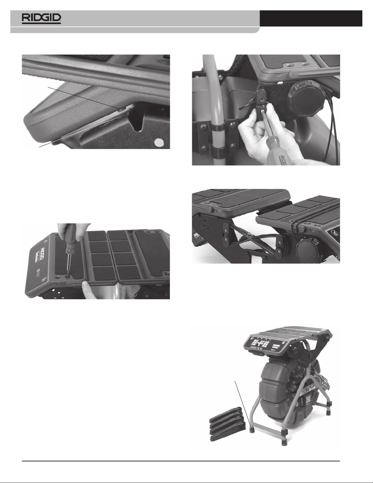
Figure 10 – Aligning the Bracket to the Side Plate
Figure 12 – Attaching the SeeSnake System Cable
7. Insert the four screws through the mounting brack-
NOTICE
When connecting/disconnecting the SeeSnake
et and side plate into their individual nuts and hand
system cable, turn only the locking sleeve. To prevent dam-
tighten.
age, do not bend or twist the connector or cable.
Figure 11 – Near Side-Plate Mounted
8. Repeat the process with the other side plate and
mounting bracket. The two side plates should be
Figure13–MountingRight-HandPlatform
level.
9. Route the SeeSnake System Cable from the See-
10. Mount the right hand (keyboard) platform by align-
Snake between the side plates and connect it to
ing it with the mounting holes in the flanges of the
the SeeSnake Connector on the bottom of the
side plates and screw it hand tight with four screws.
right-hand platform. The SeeSnake System Cable
Adjust the platform so it is level.
has a guide ridge molded into the top of the cable
connector. With the guide ridge aligned with the
guide pin of the receptacle, insert the System Ca-
ble into the System Connector firmly and turn the
locking sleeve clockwise to tighten it in position.
9
SeeSnake® LT1000
Pin
Hole
Figure14–AlignmentPinandHole
A small alignment pin at each end of each platform
Figure 16 – Mounting the Cord-Wrap (Note USB Cable
should fit into a matching hole to seat the platform side
captured under Cord-Wrap)
fully.
11. Locate the left hand laptop platform, which is the
one without the keyboard. Align it to the four holes
(in the flanges of the side plates) and insert the four
screws and hand-tighten them.
Figure17–Cord-wrapandUSBCable
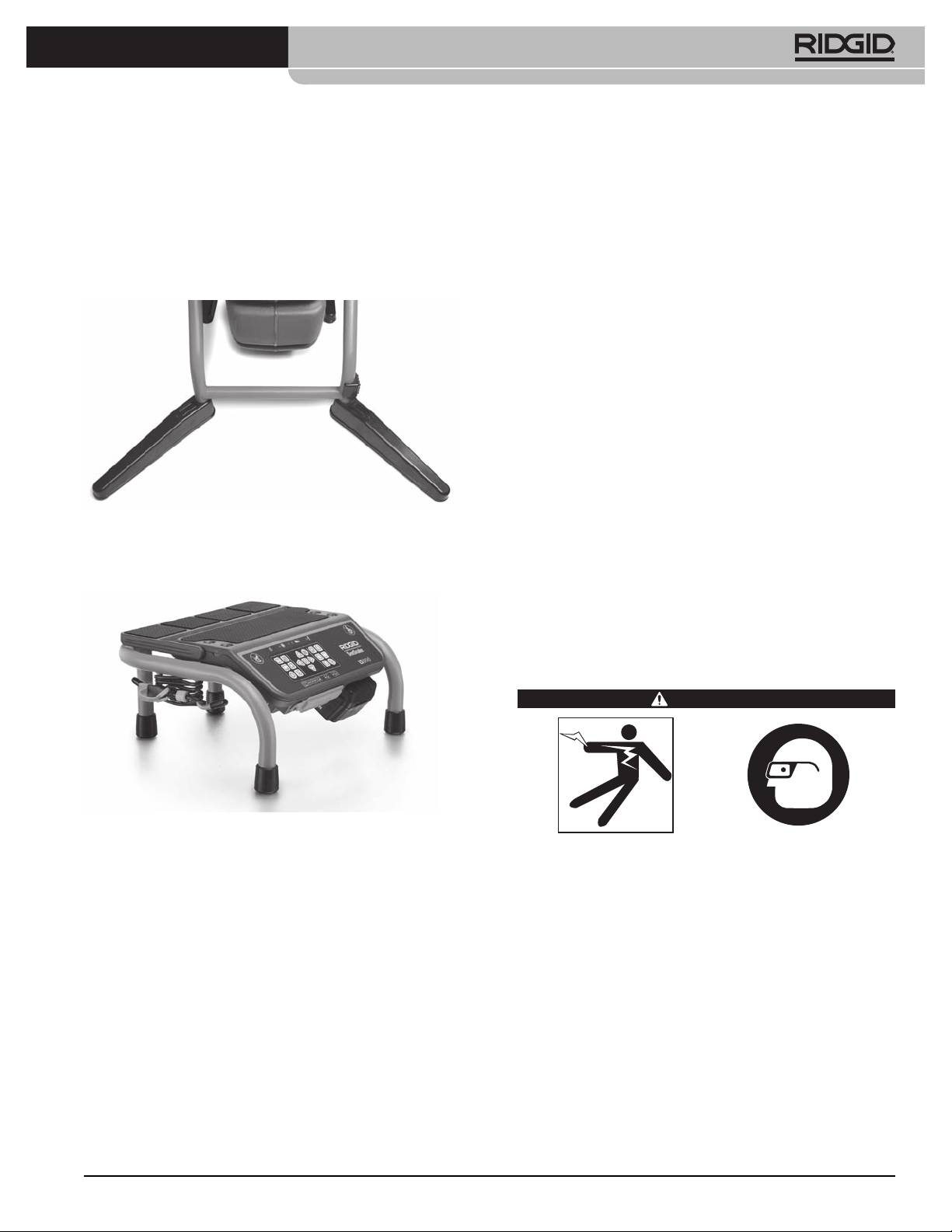
Installing the Stabilizers
Stabilizers are supplied with the LT1000 which provide
Figure15–MountingtheLeft-HandPlatform
greater reel stability when they are rotated out. Each
stabilizer has a spring-loaded plate inside it which
holds the stabilizer in place when installed.
12. Adjust the platforms and side plates so the plat-
forms are aligned and level. Fully tighten down the
screws on the brackets and the mounting screws
for the laptop platforms.
13. Replace the right-hand cord-wrap and fasten it into
place with two screws. Note that the USB cable is
captured under the cord-wrap post as it exits the
LT1000.
Rubber Foot
Figure18–StabilizerswithMiniReel
10
SeeSnake® LT1000
To install the stabilizers:
You must install SeeSnake HQ and its drivers before con-
necting the LT1000 to your computer.
1. Remove the rubber foot from a leg of the frame.
1. Insert the CD into the computer’s CD drive.
2. Slide the stabilizer onto the leg of the frame, with
the solid face toward the top of the frame.
2. The laptop should auto-detect the CD and begin
the installation process. It may ask for an admin
3. Replace the rubber foot and seat it firmly.
password before installing the HQ software.
4. Repeat for all four legs. On the larger Standard unit,
3. When the software installation is complete, eject
install stabilizers only on the legs without wheels.
the CD and store it in a safe place.
NOTE! Software update checks will occur automatically
when the laptop is connected to the Internet. If an
update is detected you will be asked if you want to
install it, and the update will occur automatically
if you indicate you want it installed. The latest ver-
sion can be checked for manually by placing the
laptop on-line and pointing an Internet browser
to http://www.hq.ridgid.com/product-hq.php.
4. Alternatively the software may be installed by brows-
ing to the updates website given above and follow-
ing the instructions found there.
Figure 19 – Stabilizers installed
5. For detailed instructions on using HQ software to
manage your video clips, still photos, reports, cus-
LT1000 Mini
tomer information and formats, direct a web-con-
nected browser to http://www.hq.ridgid.com/. You
will find on-line user instructions for every aspect of
HQ’s capabilities there.
Pre-Operation Inspection
WARNING
Figure 20 – LT1000 Mini
Before each use, inspect your SeeSnake LT1000 and
The LT1000 Mini is a sturdy portable frame supporting
correct any problems to reduce the risk of serious
an LT1000 unit. It is light-weight, easy-to-carry and can
injury from electrical shock or other causes and pre-
be used with any SeeSnake reel simply by connecting
vent machine damage.
the SeeSnake System Cable. It is an economical alterna-
1. Confirm that the power is OFF, any external power
tive if you need to shift your LT1000 between SeeSnake
and cords are disconnected and the battery is re-
reels frequently. The LT1000 Mini is shipped with the
moved. Inspect the cords, cables and connectors for
LT1000 unit already installed on the portable frame.
damage or modification.
2. Clean any dirt, oil or other contamination from the
Preparing the Laptop
SeeSnake LT1000 to aid in inspection and to pre-
To operate correctly with the LT1000, the laptop to be
vent the unit from slipping from your grip while
used must have SeeSnake HQ software installed on it.
transporting or using.
HQ software enables you to create, manage and store
3. Inspect the LT1000 for any broken, worn, missing,
images, audio and video from the LT1000. The software
misaligned or binding parts, or any other condi-
is on the CD that ships with the LT1000. To load the
tion which might prevent safe, normal operation.
software from the CD:
Ensure the LT1000 mounting brackets are securely
tightened.
11
SeeSnake® LT1000
4. Inspect any other equipment being used per its in-
LT1000 Placement
structions to make sure it is in good usable condi-
Position the SeeSnake Reel at the work site before
tion.
mounting the laptop onto the LT1000. To access the
5. If any problems are found, do not use the unit until
carrying handle for the SeeSnake Reel, fold the platform
the problems are corrected.
wings back on both sides of the LT1000. The retaining
cord may be routed under the platform and hooked to
Work Area and Equipment Set Up
the cord hooks for transport.
Place the reel and LT1000 to allow easy access and
WARNING
viewing while manipulating the camera and pushrod
for an inspection. Make sure that the location is not wet
and will not let the LT1000 and other equipment get
wet during use. The LT1000 is not waterproof and ex-
posure to wet conditions can cause electrical shock or
equipment damage.
Mounting the Laptop
Set up the LT1000 and work area according to these
1. Loosen the retaining cord by turning the capstan
procedures to reduce the risk of injury from electri-
clockwise.
cal shock, fire and other causes, and to prevent dam-
age to the LT1000.
2. Place the laptop squarely on the laptop platform
with the keyboard toward the LT1000 keypad.
1. Check work area for:
3. Route the elastic retaining cord over the laptop
• Adequate lighting.
and hook it over the cord hooks, routing the cord
• Flammable liquids, vapors or dust that may ig-
so as not to interfere with the laptop’s operation.
nite. If present, do not work in area until sources
have been identified and corrected. The LT1000
4. Rotate the capstan handle counter-clockwise to
is not explosion proof. Electrical connections can
tighten the retaining cord firmly.
cause sparks.
5. Lead the LT1000 USB cord to the laptop’s USB port
• Clear, level, stable dry place for operator. Do not
and plug it into the port. Wrap any excess cord onto
use the machine while standing in wa ter.
the USB cord wraps. (See Figure 7.)
• Clear path to electrical outlet, that does not con-
Retaining
Capstan
Keypad
tain any potential sources of damage for the
Cord
Handle
power cord, when using external power.
2. Inspect the work to be done if possible, determine
the drain access point(s), size(s) and length(s), pres-
ence of drain cleaning chemicals or other chemi-
cals, etc. If chemicals are present, it is important to
under stand the specific safety measures required
to work around those chemicals. Contact the
chemical manufacturer for required information.
3. Determine the correct equipment for the application.
The SeeSnake LT1000 is made to view inspections
done with an inspection camera. Inspec tion equip-
USB Cord Transmitter Clip-On Terminal
ment for other applications can be found by consult-
Figure21–Keypad,CapstanandUSBCord
ing the RIDGID Catalog, online at www.RIDGID.com
or www.RIDGID.eu.
Note that in constrained locations or on slanted sur-
4. Make sure all equipment has been properly in-
faces or roofs, you may prefer to lay the SeeSnake on its
spected.
side, unwrap the USB cord connecting the laptop and
5. Evaluate the work area and determine if any barri-
place the laptop in another secure location.
ers are needed to keep bystanders away. Bystand-
ers can distract the operator during use. If working
near traffic, erect cones or other barriers to alert
drivers.
6. If needed, remove fixture (water closet, sink, etc.) to
allow access.
12

SeeSnake® LT1000
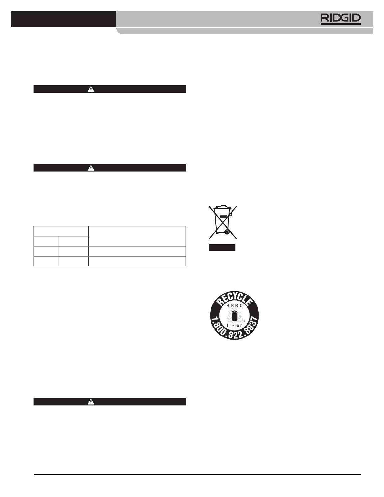
Connection Icons
ExternalPowerJack
A/VOutJack(ExternalDVDR,ect.)
VideoOutJack(ExternalMonitor)
USBPort(ThumbDrivers,ect.)
The USB ports may be used to connect an external key-
board if desired.
The front AV out jack will work even when HQ is not
being used.
ExternalMonitorOptions
1. The LT1000 may be used with an external SeeSnake
Figure 22 – Alternate Configuration For Constrained
monitor by connecting an RCA cable from the Vid-
Spaces
eo IN port on the monitor. Connect the other end
of the cable to the LT1000 video OUT port on the
back of the LT1000, marked with
.
2. The A/V out port
will pass through live video
from the SeeSnake camera connected to the LT1000
and live audio from the microphone out to a DVDR
or monitor. (If connected to a monitor which has
speakers it may cause a feedback squeal; this can
be prevented by turning the DVDR or monitor vol-
ume to minimum.)
The USB connection from the LT1000 only functions
when connected to a device running SeeSnake HQ.
Powering the SeeSnake LT1000
The SeeSnake LT1000 can either be powered with a RIDGID
Figure23–LT1000MiniwithLaptop
Li-Ion rechargeable battery or plugged into an outlet using
a supplied AC/DC power converter. Battery power is the
Connecting the LT1000
preferred powering method to reduce the risk of electrical
shock. Additionally,thepowerconverterisnotrated
External
A/VOut
foroutdooruseandshouldonlybeusedindoors.
PowerJack
USBUSBVideo Out
WARNING
Use only a battery or an isolated power
supply to power the LT1000 and any laptop used with
it to reduce the risk of Electrical shock.
BatteryPower
With dry hands, insert a charged 18V battery into the
battery holder under the right side of the keypad. A
spare battery may also be stored in the spare battery
holder under the opposite end of the LT1000 on the
opposite side. (The storage slot has no electrical con-
nections and is for convenient storage only.)
Figure 24 – LT1000 Connections
13
SeeSnake® LT1000
Battery
With dry hands, connect the two sections together and
Status
Battery
insert the jack plug into the jack on the LT1000. Route
the cord along a clear path and with dry hands plug the
power supply into a matching outlet. If using an exten-
sion cord ensure it is of adequate wire gauge. For cords
2
of 25 feet / 7,5 m, a minimum gauge of 18 AWG / 0,8 mm
is required. For cords greater than 25 feet / 7,5 m, a mini-
2
mum gauge of 16 AWG / 1,5 mm
is required.
NOTICE
If external power is unreliable and produces
transient voltage spikes, the LT1000 video may freeze. In
this case simply power cycle the LT1000 off and then on.
Figure 25 – LT1000 Connections
Job data will not be lost, but current distance count may be
reset.
Make sure that the battery locks onto the dock. See the
Battery Charger operator’s manual for more informa-
WARNING
If the laptop is plugged into AC and the
tion.
laptop AC adapter is not isolated, then a hot ground could
damage a laptop via the USB grounding connection.
Batteries supplied for the LT1000 are rated at 2.2 / 2,2 amp-
hours. When fully charged, depending on use (recording
Use only a battery or an isolated power supply to pow-
time, etc.) the LT1000 will run for approximately 2.5 / 2,5
er the LT1000 and any laptop used with it.
to 3 hours. Battery Status LEDs above keypad indicate
battery charge level. (See Battery Status LED chart.)
LT1000 Controls
NOTICE
TurntheLT1000powerOFFbeforechang-
ingorremovingthebattery. Removing the battery with
Keypad Controls
the power ON may cause loss of camera recordings.
Arrow Keys: Used to move among menu choices and
adjust variables (such as contrast) up and down. Used to
Battery Status LEDs Chart
rotate screen image.
Select Key: Used to choose options in the Units menu
BATTERY
EXTERNAL
EXTERNAL
(Auto, Meters and Feet).
STATUS
POWER NOT
POWER
MenuKey: Used to bring up a menu of display options
CONNECTED
CONNECTED
such as Color, Brightness, Contrast, Units.
FULL Solid green LEDs OFF
BrightnessKey: Used to directly control the camera LED’s
MED Solid green and red LEDs OFF
brightness up or down.
LOW Solid red, 4 beeps LEDs OFF
Microphone Mute Key: Used to mute the microphone
while recording or activate it to record comments during
DEAD Solid red for 5 sec,
LEDs OFF
an inspection.
5 sec long beep and
SondeKey: Used to activate the built-in Sonde for tracing
shutdown
the location of the camera head.
OutletPower
*ImageFlipKey:Used to flip the image on the display
vertically
For plug in operation, a double-insulated AC/DC power
supply is supplied to reduce wall outlet voltage to the
ZeroKey:Used to establish a temporary zero-point for the
distance counter for units equipped with the CountPlus.
correct voltage for the LT1000.
PowerKey:Used to power the LT1000 display ON or OFF.
NOTICE
The external power supply is intended for
*PhotoKey:Captures a still photo of the camera image as
indoor use only.
shown.
To power the system up with the power cord, locate
*VideoKey: Starts or stops the capture of a video clip.
the power supply. The power supply cord has two sec-
*AutologKey: Starts Autologging capture of a series of
tions, one of which plugs into a standard 110 - 120V
still photos stored with the current job.
two-bladed outlet (US model) or standard 230V 2 pin
*PhotoTagKey:Creates a new still photo and allows you
outlet (EU model) at one end and plugs into a power
to apply custom comments or stored tags to it.
supply at the other end. The second section runs from
*JobManagementKey: Accesses a menu of job and re-
the power supply to the back of the LT1000 and plugs
port management options.
into the jack marked
at the far left side front pan-
el of the unit (Figure 24).
*PlaybackKey: Plays back current recording, if any.
* Some of the keypad controls will have no effect unless the HQ Soft-
ware is running.
14
SeeSnake® LT1000
About HQ Software
Inspecting the Line
HQ software enables you to create, manage and store
1. Power up the LT1000 if it is OFF.
images, audio and video from the LT1000. You can use
2. Put the camera head in the line. Zero the counter if
HQ to quickly and automatically create reports which
desired.
can be emailed to a customer, or created in HTML form
3. Proceed with pipe inspection as described in your
and handed to the customer on a thumb drive, or burned
SeeSnake manual.
to DVD. HQ software also makes it easy to organize and
store job records for future reference if needed.
BrightnessAdjustment
You may find you need to increase or decrease the
HQ software is described in detail in the HQ built-in
camera LED brightness while inspecting the inside of
help files found at http://www.hq.ridgid.com/ .
a line, depending on conditions. To do so simply press
the Brightness Key
and raise or lower the brightness
Operating Instructions
level using the Arrow Keys
. Press the Menu Key
when done.
WARNING
Image Rotation
While doing an inspection the camera may become
rotated in the line and present an inverted image. The
Flip Key
will rotate the image on the screen (flip it
vertically) for easier viewing. The HQ software will also
allow you to straighten the camera image by degrees.
CountPlus Control
Always wear eye protection to protect your eyes
If you are using a SeeSnake reel equipped with the Count-
against dirt and other foreign objects.
Plus distance counter, the measured distance will ap-
When inspecting drains that might contain hazard-
pear on the display connected to the LT1000. If you
ous chemicals or bacteria, wear appropriate protec-
want to set an interim zero-point to measure distance
tive equipment, such as latex gloves, goggles, face
from some location (such as a junction or pipe-head)
shields or respirators, to prevent burns and infec-
pressing the Zero Key
will start a temporary distance
tions.
count, with the number displayed in square brackets
Do not operate this equipment if operator or ma-
[0.0]. For details on using the Zero Key see the CountPlus
chine is standing in water. Operating machine while
manual.
in water increases the risk of electrical shock. Rub-
CountPlus parameters such as date and time are set us-
ber soled, non-slip shoes can help prevent slipping
ing the CountPlus menu key and going to the Count-
and electric shock, especially on wet surfaces.
Plus Tools menu. CountPlus text overlays are managed
Follow operating instructions to reduce the risk of
with the CountPlus keypad as described in the Count-
injury from electrical shock and other causes.
Plus Operator’s Manual.
Starting Up
Locating The Camera Using The Sonde
1. Check that the unit is properly set up.
Many SeeSnake pipe inspection systems have a built-in
2. Ensure the laptop is in place and properly con-
Sonde which transmits a locatable 512Hz signal. When
nected and that the laptop has the HQ Software
the Sonde is turned ON, a locator such as the RIDGID
installed on it. Turn the laptop ON.
SR-20,SR-60,Scout™orNaviTrack®IIsetto512Hzwill
3. Place the camera head into the reel’s guide hoop
be able to detect it, allowing you to detect the camera’s
and turn the LT1000’s power ON
.
location underground.
4. When the LT1000 starts up, the laptop will detect
the SeeSnake device and will start HQ running. If
it does not, double-click the HQ icon
on your
desktop to launch it.
5. By default it will start a new Job which will come up
showing the image from the camera head.
6. For detailed instructions on the HQ software see the
built-in help files found at http://www.hq.ridgid.com/.
15
SeeSnake® LT1000
Figure 26 – Locating the Sonde
Figure 27 – LT1000 Transmitter Clip-on Terminal
To turn the SeeSnake Sonde ON while using the LT1000,
press the Sonde Key
. A Sonde icon will appear on
Set the line transmitter and the locator to the same fre-
the display while the Sonde is ON. The display may also
quency, such as 33kHz and use the locator to trace the
show some lines of interference from the Sonde’s trans-
line (Figure 28). The camera’s built-in 512Hz Sonde may
mission. These will vanish when the Sonde is turned
be on at the same time, and if your locator is equipped
OFF by again pressing the Sonde Key
.
with SimulTrace™ dual-frequency capability, you can
follow the pushrod all the way to the camera’s location
The most workable approach to tracking the Sonde is
and then detect the Sonde in the camera as you ap-
to run the pushrod into the pipe about five or ten feet /
proach it above ground.
1,5 to 3 meters and use the locator to find the Sonde’s
position. If desired, you can then extend the pushrod
Ifyoudon’thave theSimulTrace™feature,usealine
a similar distance further down-pipe and locate the
transmitter and a locator to line-trace the pushrod.
Sonde again starting from the previous located posi-
When the signal fades, switch the locator to Sonde
tion. To locate the Sonde, turn the locator ON and set
mode at the frequency of the in-line Sonde, usually
it to Sonde mode. Scan in the direction of the Sonde’s
512Hz. Pick the signal up from where the line-trace
probable location until the locator detects the Sonde.
frequency started to weaken and zero in on the in-line
Once you have detected the Sonde, use the locator in-
Sonde. Because locating frequencies from transmitters
dications to zero in on its location precisely. For detailed
can cause distortion of the image on the monitor, it is
instructions on Sonde locating, consult the Operator’s
best to turn Sonde and line transmitters OFF while in-
Manual for the locator model you are using.
specting the interior of a line and turn them ON only
when ready to do a locate.
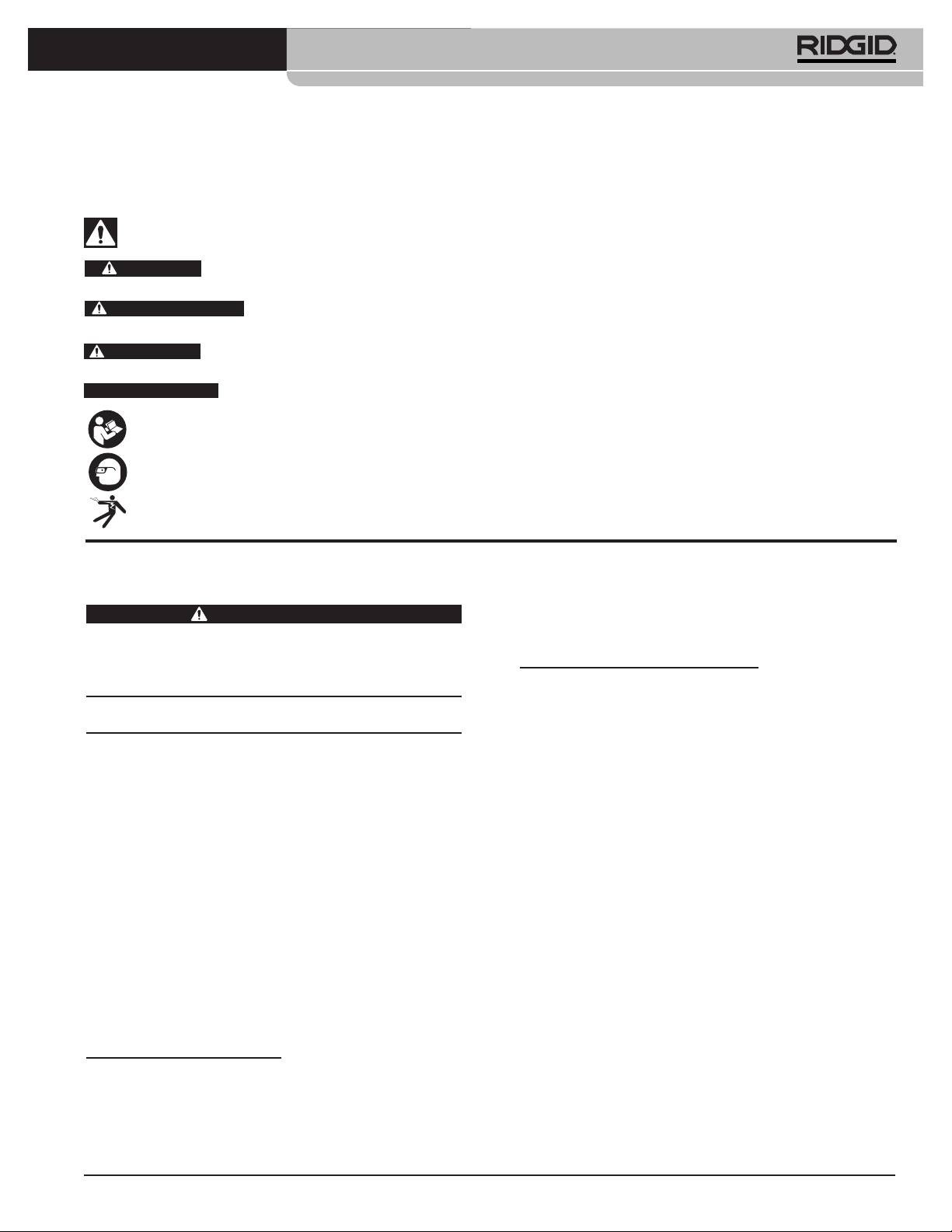
Line Tracing The SeeSnake Pushrod
The LT1000 also enables you to trace the line of the
pushrod underground, using a standard RIDGID loca-
torsuchastheNaviTrack®II,theScout™,theSR-20or
the SR-60. To line-trace the SeeSnake pushrod, simply
connect a line transmitter with one connector well-
grounded to the grounding stake and the other con-
nector clipped to the Transmitter Clip-on Terminal. The
Transmitter Clip-on Terminal is a metal lug located just
under the left end of the keyboard area as shown in Fig-
ure 27.
Figure 28 – Line Tracing the Pushrod
16
SeeSnake® LT1000
For information on your nearest RIDGID Independent
Maintenance Instructions
Service Center or any service or repair questions:
Cleaning
• ContactyourlocalRIDGIDdistributor.
• Visitwww.RIDGID.comorwww.RIDGID.eutond
WARNING
your local RIDGID contact point.
Make sure all cords and cables are disconnected and
the battery removed prior to cleaning the LT1000 to
• ContactRIDGIDTechnicalServicesDepartmentat
reduce the risk of electrical shock.
rtctechservices@emerson.com, or in the U.S. and
Canada call (800) 519-3456.
Do not use liquid or abrasive cleaners on the LT1000.
Clean with damp cloth. Do not allow liquid to enter
E-mail SeeSnake HQ Support Department at
LT1000.
HQSupport@seesnake.com
Disposal
Accessories
Parts of the unit contain valuable materials and can be
WARNING
recycled. There are companies that specialize in recy-
The following accessories have been designed to
cling that may be found locally. Dispose of the com-
function with the LT1000. Other accessories suitable
ponents in compliance with all applicable regulations.
for use with other equipment may become hazard-
Contact your local waste management authority for
ous when used with the LT1000. To reduce the risk of
more information.
serious injury, only use accessor ies specifically de-
ForECCountries: Do not dispose of electri-
signed and recommended for use with the LT1000,
cal equipment with household waste!
such as those listed in the following chart.
According to the European Guideline 2002/
Catalog #
96/EC for Waste Electrical and Electronic
Description
US EU
Equipment and its implemen tation into na-
tional legislation, electrical equipment that
32743 28218 18V Li-Ion rechargeable battery
is no longer usable must be collected separately and
27958 32073 Battery charger
disposed of in an environmentally correct manner.
Battery Disposal
Transport And Storage
For USA and Canada:The RBRC™
Remove batteries before shipping. Do not expose
(Rechargeable Battery Recycling
to heavy shocks or impacts during transport. If storing
Cor p oration) Seal on the battery
for an extended period, remove batteries. Store within
packs means that RIDGID has al-
temperature range of 14°F to 158°F / -10°C to 70°C.
ready paid the cost of recycling the
Store electrical devices in a dry place to reduce the risk
lithium-ion battery packs once they
of electrical shock.
have reached the end of their use-
ful life.
Protect against excessive heat. The unit should be situ-
ated away from heat sources such as radiators, heat
RBRC™,RIDGID®,andotherbatterysuppliershavedevel-
registers, stoves or other products (including amplifi-
oped programs in the USA and Canada to collect and re-
ers) that produce heat.
cycle rechargeable batteries. Normal and rechargeable
batteries contain materials that should not be directly
disposed of in nature, and contain valuable materials
Service And Repair
that can be recycled. Help to protect the environment
and conserve natural resources by returning your used
WARNING
batteries to your local retailer or an authorized RIDGID
Improper service or repair can make the LT1000 un-
service center for recycling. Your local recycling center
safe to operate.
can also provide you with additional drop off locations.
Service and repair of the SeeSnake LT1000 and LT1000
RBRC™isaregisteredtrademarkoftheRechargeable
Mini must be performed by a RIDGID Independent
Battery Recycling Corporation.
Auth orized Service Center.
ForECcountries: Defective or used battery packs/bat-
teries must be recycled according to the guideline
2006/66/EC.
17

SeeSnake® LT1000
Chart 1 Troubleshooting
PROBLEM PROBABLE FAULT LOCATION SOLUTION
Camera video image not
No power to SeeSnake. Check power is correctly plugged in or bat-
seen.
tery is charged.
Check Power Key on LT1000 by pressing.
Connections faulty. Check connection to LT1000 unit from
SeeSnake.
Batteries Low. Check seating and pin condition in the Se-
eSnake System connection. Clean if need-
ed.
Recharge batteries or connect external pow-
er supply.
Flashing Battery Warning
LT1000 18V batteries low. Recharge LT1000 batteries. Switch to AC pow-
appears.
er (110 - 240V AC).
LT1000videofreezes. Low-quality AC power or voltage spike. Power cycle the LT1000 OFF and then ON.
Novideo. If your computer doesn’t recognize the
Restart your computer, power cycle LT1000
USB connection.
or close HQ and restart it to see if this cor-
rects the problem.
Do not start your computer with the LT1000
The LT1000 should be turned OFF, though
turned ON.
it’s ok to have the USB cable plugged in.
NOTE: The USB connector (See Figure 12)
on the LT1000 was designed to be a water-
resistant seal, so it is a tight fit. Your LT1000
was tested and shipped with this cable
firmly connected. If you need to disconnect
and reconnect this cable (for example, if you
break your USB cable), make sure you push
the connector in all the way. If you don’t,
the HQ software might not recognize the
LT1000. If so, make sure you have pushed
the connector in all the way. You may have
to restart HQ to recognize the connection.
18
®
SeeSnake
LT1000
®
SeeSnake
LT1000
AVERTISSEMENT
Familiarisez-vous soigneusement
avec ce mode d’emploi avant
d’utiliser l’appareil. Tout manque
®
de compréhension ou de respect
SeeSnake
LT1000
des consignes ci-devant aug-
Pour future référence, enregistrez ci-dessous le numéro de série indiqué sur la plaque
menterait les risques de choc élec-
signalétique de l’appareil.
trique, d’incendie et/ou de grave
Nº de
blessure corporelle.
série

®
SeeSnake
LT1000
Table des matières
Fiche dʼenregistrement du numéro de série de lʼappareil ......................................................................................19
Symboles de sécurité ................................................................................................................................................21
Consignes générales de sécurité
Sécurité des lieux......................................................................................................................................................21
Sécurité électrique ....................................................................................................................................................21
Sécurité individuelle ..................................................................................................................................................22
Utilisation et entretien du matériel ............................................................................................................................22
Utilisation et entretien de lʼappareil à piles................................................................................................................22
Service après-vente ..................................................................................................................................................23
Consignes de sécurité spécifiques ..........................................................................................................................23
Sécurité de la LT1000 ..............................................................................................................................................23
Description, caractéristiques et équipements de base
Description ................................................................................................................................................................24
Caractéristiques ........................................................................................................................................................24
Caractéristiques du portable ....................................................................................................................................24
Equipements de base ..............................................................................................................................................24
Accessoires ..............................................................................................................................................................24
Composants de la LT1000..........................................................................................................................................25
Icônes ..........................................................................................................................................................................25
Assemblage
Montage de la LT1000 ..............................................................................................................................................25
Montage de la LT1000 sur enrouleur SeeSnake mini...............................................................................................25
Montage de la LT1000 sur enrouleur SeeSnake standard .......................................................................................26
Montage des stabilisateurs .......................................................................................................................................28
LT1000 Mini ..............................................................................................................................................................29
Préparation du portable ............................................................................................................................................29
Inspection préalable....................................................................................................................................................29
Préparation des lieux et du matériel
Positionnement de la LT1000 ..................................................................................................................................30
Installation du portable..............................................................................................................................................30
Raccordement de la LT1000 ....................................................................................................................................31
Allumage de la SeeSnake LT1000 ..........................................................................................................................31
Commandes de la LT1000
Commandes du clavier ............................................................................................................................................32
Description du logiciel HQ ........................................................................................................................................33
Consignes dʼutilisation
Mise en route ............................................................................................................................................................33
Inspection des conduites ..........................................................................................................................................33
Réglage de luminosité ............................................................................................................................................33
Rotation dʼimage ....................................................................................................................................................33
Commandes du CountPlus ....................................................................................................................................33
Localisation de la caméra à lʼaide de la sonde ........................................................................................................33
Traçage du câble SeeSnake ....................................................................................................................................34
Consignes dʼentretien
Nettoyage..................................................................................................................................................................35
Accessoires ................................................................................................................................................................35
Transport et stockage ................................................................................................................................................35
Révisions et réparations ............................................................................................................................................35
Recyclage ....................................................................................................................................................................35
Recyclage des piles ....................................................................................................................................................35
Dépannage ..................................................................................................................................................................36
Garantie à vie ..........................................................................................................................................Page de garde
*Traduction de la notice originale
20
®
SeeSnake
LT1000
Symboles de sécurité
Des symboles et mots clés spécifiques, utilisés à la fois dans ce mode dʼemploi et sur lʼappareil lui-même, servent à signaler
dʼimportants risques de sécurité. Ce qui suit permettra de mieux comprendre la signification de ces mots clés et symboles.
Ce symbole sert à vous avertir aux dangers physiques potentiels. Le respect des consignes qui le suivent vous permettra dʼéviter
les risques de blessures graves ou mortelles.
Le terme DANGER signifie une situation dangereuse potentielle qui, faute dʼêtre évitée, provoquerait la mort ou de
DANGER
graves blessures corporelles.
Le terme AVERTISSEMENT signifie une situation dangereuse potentielle qui, faute dʼêtre évitée, serait sus-
AVERTISSEMENT
ceptible dʼentraîner la mort ou de graves blessures corporelles.
Le terme ATTENTION signifie une situation dangereuse potentielle qui, faute dʼêtre évitée, serait susceptible
ATTENTION
dʼentraîner des blessures corporelles légères ou modérées.
AVIS IMPORTANT
Le terme AVIS IMPORTANT signifie des informations concernant la protection des biens.
Ce symbole indique la nécessité de lire le manuel soigneusement avant dʼutiliser le matériel. Le mode dʼemploi renferme
dʼimportantes informations concernant la sécurité dʼutilisation du matériel.
Ce symbole indique le port obligatoire de lunettes de sécurité intégrales lors de la manipulation ou utilisation du matériel.
Ce symbole indique un risque de choc électrique.
Consignes générales de sécurité
prise, retournez-la. Si elle ne rentre toujours pas,
demandez à un électricien qualifié dʼinstaller une
AVERTISSEMENT
prise polarisée. Ne modifiez la fiche dʼaucune
Familiarisez-vous avec lʼensemble du mode dʼemploi. Le
manière.
non-respect des consignes dʼutilisation et de sécurité ci-
Modèle pour lʼUnion Européenne
après augmenterait les risques de choc électrique,
dʼincendie et/ou de grave blessure corporelle.
• Les outils à double isolation sont équipés dʼune
CONSERVEZ CES INSTRUCTIONS POUR
fiche à 2 broches non polarisée. La double isolation
FUTURE REFERENCE !
élimine le besoin de relier lʼappareil à la terre via un cir-
cuit à trois fils.
Sécurité des lieux
• Evitez tout contact physique avec les objets reliés
• Assurez-vous de la propreté et du bon éclairage
à la terre tels que canalisations, radiateurs, cuisi-
des lieux. Les zones encombrées ou mal éclairées
nières et réfrigérateurs. Tout contact avec la terre
sont une invitation aux accidents.
augmenterait les risques de choc électrique.
• Nʼutilisez pas ce matériel en présence de matières
• Nʼexposez pas lʼappareil à la pluie ou aux intem-
explosives telles que liquides, gaz ou poussières
péries. Toute pénétration dʼeau à lʼintérieur de ce
combustibles. Les appareils électriques produisent
matériel augmenterait les risques de choc électrique.
des étincelles susceptibles dʼenflammer les pous-
sières et émanations combustibles.
• Ne maltraitez pas le cordon dʼalimentation de
lʼappareil. Nʼutilisez pas le cordon dʼalimentation
• Eloignez les enfants et les curieux lors de lʼutilisation
pour transporter, tirer ou débrancher lʼappareil.
dʼun appareil électrique. Les distractions risquent de vous
Eloignez le cordon dʼalimentation des sources de
faire perdre le contrôle de lʼappareil.
chaleur, de lʼhuile, des objets tranchants et des
mécanismes actifs. Les cordons dʼalimentation en-
Sécurité électrique
dommagés ou enchevêtrés augmentent les risques
Modèle pour les Etats-Unis
de choc électrique.
• Les appareils à double isolation sont équipés
• Lorsquʼil est inévitable de travailler dans des en-
dʼune fiche polarisée dont lʼune des broches est
droits mouillés, utilisez une source dʼalimentation
plus large que lʼautre. Cette fiche ne sʼintroduit
protégée par disjoncteur différentiel (GFCI). La
dans une prise polarisée que dans un sens. Si la
présence dʼun disjoncteur différentiel limite les risques
fiche ne sʼintroduit pas complètement dans la
de choc électrique.
21

®
SeeSnake
LT1000
• Maintenez toutes connexions électriques au sec et
nombreux accidents sont provoqués par des appareils
en élévation. Ne pas toucher le matériel et ses
mal entretenus.
fiches électriques avec les mains mouillées. Cela
• Lors de lʼutilisation de ce matériel et des acces-
limitera les risques de choc électrique.
soires éventuels, respectez les consignes du mode
dʼemploi en tenant compte des conditions et du
Sécurité individuelle
type de travail envisagé. Lʼutilisation de ce matériel à
• Soyez attentif, faites attention à ce que vous faites
des fins autres que celles prévues pourrait augmenter
et faites preuve de bon sens. Nʼutilisez pas ce
les risques dʼaccident.
matériel lorsque vous êtes sous lʼinfluence de
• Utilisez exclusivement les accessoires prévus par le fab-
drogues, de lʼalcool ou de médicaments. Lors de
ricant pour votre type dʼappareil particulier. Toute tentative
lʼutilisation de ce type dʼappareil, un instant dʼinattention
dʼadaptation dʼaccessoires prévus pour dʼautres types
risque dʼentraîner de graves lésions corporelles.
dʼappareil pourrait sʼavérer dangereuse.
• Prévoyez les équipements de protection individu-
• Maintenez les poignées de lʼappareil en bon état de
elle nécessaires. Portez systématiquement une
propreté et éliminez la moindre trace dʼhuile ou de
protection oculaire. Le port dʼun masque à pous-
graisse. Cela permettra de mieux tenir lʼappareil.
sière, de chaussures de sécurité antidérapantes, dʼun
casque de chantier ou de protecteurs dʼoreilles
Utilisation et entretien des appareils à
sʼimpose lorsque les conditions lʼexigent.
piles
• Ne vous mettez pas en porte-à-faux. Maintenez
• Utilisez exclusivement le type de chargeur pré-
une bonne position de travail et un bon équilibre à
conisé par le fabricant. Lʼutilisation de tout autre
tout moment. Cela vous permettra de mieux con-
type de chargeur augmenterait les risques dʼincendie.
trôler lʼappareil en cas dʼimprévu.
• Nʼutilisez que les piles spécifiquement désignées
• Habillez-vous de manière appropriée. Le port de
pour ce type dʼappareil. Lʼemploi de tout autre type
vêtements amples et de bijoux est à proscrire.
de bloc-piles augmenterait les risques de blessure et
Eloignez vos cheveux, vos vêtements et vos gants
dʼincendie.
des mécanismes. Les vêtements amples, les bijoux
et les cheveux longs risquent dʼêtre entraînés dans le
• Ne jamais sonder la pile à lʼaide dʼun objet mé-
mécanisme.
tallique. Lorsque le bloc-piles ne sert pas, rangez-
le à lʼabri des objets métalliques (trombones, clés,
Utilisation et entretien du matériel
clous, vis, etc.) qui risqueraient de ponter ses
• Ne forcez pas le matériel. Prévoyez le matériel ap-
deux bornes. Le pontage des deux bornes de la pile
proprié en fonction des travaux envisagés. Un
pourrait provoquer des brûlures ou un incendie.
matériel approprié aux travaux envisagés assurera
• Evitez tout contact avec lʼélectrolyte qui pourrait
une plus grande efficacité et sécurité.
éventuellement gicler de la pile en présence de
• Nʼutilisez pas de matériel électrique dont
conditions abusives. En cas de contact accidentel,
lʼinterrupteur ne contrôle pas la mise en marche ou
rincez la peau à lʼeau courante. En cas de contact
lʼarrêt. Tout appareil électrique qui ne peut pas être
oculaire, consultez ensuite un médecin. Lʼélectrolyte
contrôlé par son interrupteur est dangereux et doit
éjecté par la pile risque de provoquer des irritations ou
être réparé.
des brûlures.
• Débranchez lʼappareil et/ou retirez son bloc-piles
• Utilisez et rangez les piles et leur chargeur dans un
avant de le régler, de changer ses accessoires ou
endroit sec et à température ambiante appropriée.
de le ranger. De telles mesures préventives limiteront
Les températures extrêmes et lʼhumidité peuvent en-
les risques de blessure.
dommager les piles et entraîner des fuites, des chocs
• Rangez tout appareil non utilisé hors de la portée
électriques, des incendies ou des brûlures. Consultez
des enfants et des individus qui nʼont pas été fa-
le manuel du chargeur pour plus de précisions.
miliarisés avec ce type de matériel ou son mode
• Ne pas recouvrir le chargeur lorsquʼil est en cours
dʼemploi. Ce type de matériel peut devenir dangereux
de charge. Son bon fonctionnement dépend dʼune
sʼil tombe entre les mains dʼutilisateurs non initiés.
ventilation adéquate. Recouvrir un chargeur en cours
• Veillez à lʼentretien de lʼappareil. Examinez-le pour
dʼutilisation pourrait provoquer un incendie.
signes de désalignement, de grippage, dʼabsence ou de
bris de ces composants, et de toute autre anomalie qui
• Recyclez les piles de manière appropriée. Dans
risquerait de nuire à son bon fonctionnement. Le cas
la mesure où des températures élevées peuvent
échéant, faire réparer lʼappareil avant de lʼutiliser. De
provoquer lʼexplosion des piles, ne les jetez pas au feu.
22

®
SeeSnake
LT1000
Certains pays ont réglementé le recyclage des piles.
bonne mise à la terre de la prise. En cas de doute, il
Veuillez respecter toute réglementation en vigueur.
conviendra de faire inspecter la prise par un élec-
tricien.
Service après-vente
• Nʼalimentez la LT1000 que par pile ou à lʼaide dʼun
• Confiez ce matériel à un réparateur agréé nʼutilisant
câble dʼalimentation isolé, voire les piles ou le
que des pièces de rechange identiques. Cela as-
câble dʼalimentation du portable concerné. Cela
surera la sécurité du matériel.
minimisera les risques de problèmes électriques dus à
lʼhumidité ou au mauvais état du réseau dʼalimentation.
• Retirez les piles et confiez la réparation de lʼappareil à
un réparateur agréé en cas de :
• Ne pas utiliser ce matériel lorsque lui ou son util-
isateur a les pieds dans lʼeau. La présence dʼeau
• Fuite dʼélectrolyte ou introduction dʼobjets dans le produit.
augmente les risques de choc électrique.
• Mauvais fonctionnement du produit selon les con-
signes dʼutilisation applicables.
• La LT1000 nʼest pas étanche. Elle résiste à la pous-
• Chute ou choc du produit.
sière et aux éclaboussures. Ne pas exposer ce
matériel à lʼeau ou aux intempéries. Cela augmenterait
• Changement notable dans les performances du pro-
les risques de choc électrique.
duit.
• Ne pas utiliser ce matériel en présence dʼun risque
de contact avec une source de haute tension. Ce
Consignes de sécurité
matériel nʼest pas conçu pour assurer une protection ou
spécifiques
isolation contre la haute tension.
AVERTISSEMENT
• Avant dʼutiliser la LT1000, familiarisez-vous à la fois
La section suivante contient dʼimportantes consignes de
avec le présent mode dʼemploi et celui de tout
sécurité qui sʼadressent spécifiquement à ce type de
autre matériel associé. Le non-respect de lʼensemble
matériel.
de leurs consignes augmenterait les risques de dégâts
Afin de limiter les risques dʼincendie et de choc électrique
matériels et/ou de blessure grave.
ou autres blessures graves, lisez le mode dʼemploi
soigneusement avant dʼutiliser la LT1000.
• Prévoyez les équipements de protection individuelle
appropriés lors de la manipulation et utilisation de
CONSERVEZ CES INSTRUCTIONS !
ce matériel dans les conduites dʼeaux usées. Les
Gardez ce mode dʼemploi avec lʼappareil pour quʼil soit à la
conduites dʼévacuation peuvent renfermer des pro-
disposition de tout utilisateur éventuel.
duits chimiques, des bactéries ou autres substances po-
Au besoin, une copie de la Déclaration de conformité CE
tentiellement toxiques ou infectieuses et susceptibles de
nº 890-011-320.10 accompagnera le présent manuel
provoquer des brûlures ou autres lésions. Les
sous forme de notice indépendante.
équipements de protection individuelle comprennent
®
systématiquement lunettes de sécurité et, selon le cas
En cas de questions concernant ce produit RIDGID
:
peuvent inclure les gants ou mitaines de curage, les
– Pour toutes questions concernant HQ, contactez le ser-
gants en latex ou caoutchouc, les lunettes étanches ou
vice dʼassistance HQ à HQSupport@seenake.com.
visières de sécurité, les vêtements de protection, les ap-
– Consultez votre distributeur RIDGID.
pareils respiratoires et les chaussures de sécurité.
– Consultez les sites www.RIDGID.com ou
• Lors de lʼutilisation dʼun appareil de curage en con-
www.RIDGID.eu pour localiser le représentant
jonction avec le matériel dʼinspection, portez sys-
RIDGID le plus proche.
tématiquement des gants de curage RIDGID. Ne
– Consultez les services techniques de RIDGID par
jamais appréhender un câble en rotation avec un autre
mail adressé à rtctechservices@emerson.com, ou, à
type de gant ou un chiffon. Ces derniers risqueraient de
partir des Etats-Unis et du Canada, en composant le
sʼentortiller autour du câble et blesser vos mains. Si vous
(800)519-3456.
portez des gants en latex ou en caoutchouc, portez
des gants de curage RIDGID par-dessus. Ne jamais
Sécurité de la LT1000
porter de gants de curage endommagés.
• Une prise de courant ayant une terre défectueuse
risque de provoquer des chocs électriques ou
• Respectez les normes dʼhygiène applicables. Après
dʼendommager le matériel. Assurez-vous systéma-
chaque manipulation du matériel dʼinspection, lavez
tiquement de la bonne mise à la terre de la prise élec-
vos mains et autres parties du corps exposées au con-
trique utilisée. La simple présence dʼune barrette de
tenu des conduites dʼévacuation à lʼeau chaude savon-
terre ou dʼun disjoncteur différentiel ne garantit pas la
neuse. Ne jamais manger ou fumer lors de lʼutilisation
23

®
SeeSnake
LT1000
ou manipulation du matériel dʼinspection. Cela limitera
LT1000 Mini
les risques de contamination en présence de sub-
Poids .............................6.1 livres / 2,78 kg sans pile ;
stances toxiques ou infectieuses.
7.4 livres / 3,4 kg avec piles
(sans portable)
Dimensions :
Description, caractéristiques
Longueur .....................13.6" / 34,5 cm
et équipements de base
Largeur ........................11.9" / 30,2 cm
Description
Hauteur........................6.5" / 16,5 cm
®
La SeeSnake
LT1000 est une plate-forme dʼinterface pra-
Paramètres du portable
tique qui permet de transformer tout ordinateur portable en
®
®
• Windows
7, Windows Vista
(SP2), Windows XP
moniteur dʼinspection SeeSnake afin de capter les images,
(SP3) (Windows 7 recommandé)
vidéos et enregistrements sonores renvoyés par un sys-
®
®
• Intel
Pentium
ou AMD Athion™ 1.8GHz / 1,8GHz
tème dʼinspection de conduites SeeSnake. Elle sert égale-
(2.4GHz / 2,4GHz ou plus recommandé) ou Intel
ment dʼinterface avec le gestionnaire dʼimages et rapports
Core™ 2 Duo 2.4GHz / 2,4GHz
SeeSnake HQ afin de faciliter et simplifier la création et la
• Mémoire système GB (2 GB recommandé)
gestion des rapports client.
®
• Carte graphique compatible avec DirextX
9 ou 10
La LT1000 sert également de support robuste sur lequel
de 128 MB (256 MB ou plus recommandé)
®
installer, connecter et éventuellement retirer votre portable
• Carte sonore compatible avec DirextX
9 ou plus
en un clin dʼœil. Deux rallonges latérales sont prévues
• 30 GB dʼespace disque
pour augmenter la surface de travail. Ces deux rallonges
• Lecteur CD-ROM ou connexion Internet pour le
peuvent être soit repliées individuellement afin de créer
téléchargement des logiciels
une plate-forme de soutien sur le SeeSnake lui-même, soit
• Port USB 2.0
déployées pour augmenter la surface de travail de par et
• Facultatif – Graveur DVD pour la création de rap-
dʼautre de la LT1000.
ports sur DVD. Connexion Internet pour transfert
des rapports par courrier électronique, télécharge-
Caractéristiques
ment des rapports vers Ridgid Connect, etc.
Résolution dʼécran minimale recommandée : 1024
LT1000
x 768
Poids .............................6.4 livres / 2,9 kg sans pile ;
7.35 livres / 3,3 kg avec pile
Equipements de base
(sans portable)
• LT1000
Dimensions :
• Convertisseur de courant 100 - 220V / 15V
• Mode dʼemploi
Longueur avec
• Instructions sur DVD
rallonges repliées .........20.6" / 52,3 cm
• 4 stabilisateurs
Longueur avec
• Câble USB
rallonges déployées ....21.7" / 55,1 cm
Largeur, standard ........12.8" / 32,5 cm
Accessoires
Largeur, expédition......11.9" / 30,2 cm
Parmi les autres équipements compatibles avec la
Hauteur........................6.5" / 16,5 cm
SeeSnake LT1000 se trouvent :
Alimentation...................Secteur 100 à 240V / 50 à
• Pile rechargeable
®
60Hz ou pile rechargeable
• Les localisateurs/récepteurs RIDGID
type SR-20,
®
®
18V
SR-60, Scout
, NaviTrack
II, etc.
®
• Les transmetteurs RIDGID
ST-510, ST-305,
Type de pile...................1Li-ion 18V, 2.2Ah / 2,2Ah
®
®
ST-33Q, NaviTrack
Brick, NaviTrack
10W.
Puissance nominale ......14 à 16V 40W
• Le compteur de distance CountPlus Cable Counter
Milieu opérationnel
qui fait normalement partie des systèmes
Température................-4°F à 167°F / -20°C à 75°C
dʼinspection de conduite SeeSnake.
Humidité relative..........5 à 95%
La LT1000 est protégée par plusieurs brevets améri-
Altitude ........................13,120 pieds / 4.000 m
cains et internationaux.
24
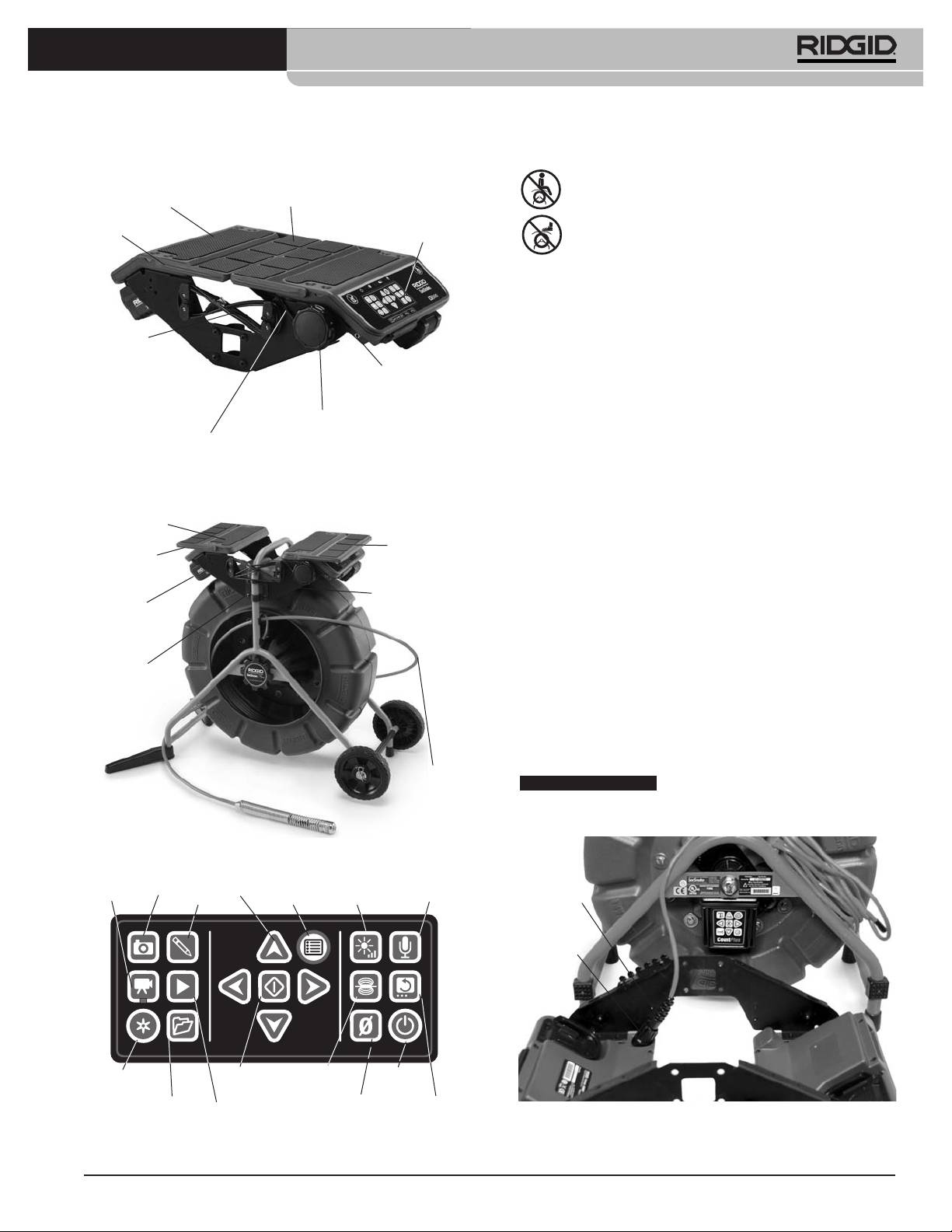
®
SeeSnake
LT1000
Composants de la LT1000
Icônes
Plate-forme de
Ne pas sʼasseoir sur la LT1000
portable
Rallonges de plate-forme
Flasque
Clavier
Ne pas monter sur la LT1000
Assemblage
Montage de la LT1000
Cordon USB
La LT1000 se monte facilement et rapidement sur tout
enrouleur SeeSnake Standard ou Mini à lʼaide dʼun
Couvercle
7
tournevis cruciforme et dʼune clé à œillet de
/
16
" / 11 mm.
du transmetteur
Le processus de montage sur SeeSnake Mini diffère de
celui du SeeSnake Standar
Cabestan
Bretelle dʼarrimage
A noter que les parties recourbées des supports de fix-
de portable
ation sont orientées vers lʼextérieur sur la LT1000, tan-
Figure 1 – Rallonges de plate-forme repliées
dis quʼen raison de son gabarit réduit, ceux de la Mini
LT1000 sont repliés vers lʼintérieur.
Plate-forme de
Rallonges de plate-forme déployées
portable
Montage de la LT1000 sur enrouleur
Rallonge de
Rallonge de
plate-forme
SeeSnake Mini Reel
plate-forme
1. Retirez les deux supports de fixation latéraux de la
Flasque
LT1000.
Pile 18V
2. Avant de monter la LT1000 sur le cadre, amenez le
câble de connexion du SeeSnake jusquʼà la prise
Supports
de fixation
SeeSnake. La fiche du câble de connexion est
pourvue dʼun bossage permettant de lʼaligner sur la
broche de guidage de la prise correspondante.
Introduisez la fiche du câble de connexion à fond
dans la prise, puis tournez le collier de verrouillage en
sens horaire pour lʼarrimer.
Câble de
connexion
AVIS IMPORTANT
Lors de la connexion ou déconnex-
SeeSnake
ion du câble SeeSnake, ne tournez que le collier de ver-
rouillage afin de ne pas endommager sa fiche.
Figure 2 – Composants de la LT1000
Onglet
Sourdine
Photo
Flèches
Vidéo
photo
Menu
Luminosité
micro
Guide
Collier de
verrouillage
Sauvegarde
Sélection
Sonde
Marche
automatique
/Arrêt
Gestion
Rotation
Lecture
Remise
Figure 4 – Raccordement du câble de connexion avant
chantiers
à zéro
dʼimage
montage
Figure 3 – Clavier de la LT1000
25
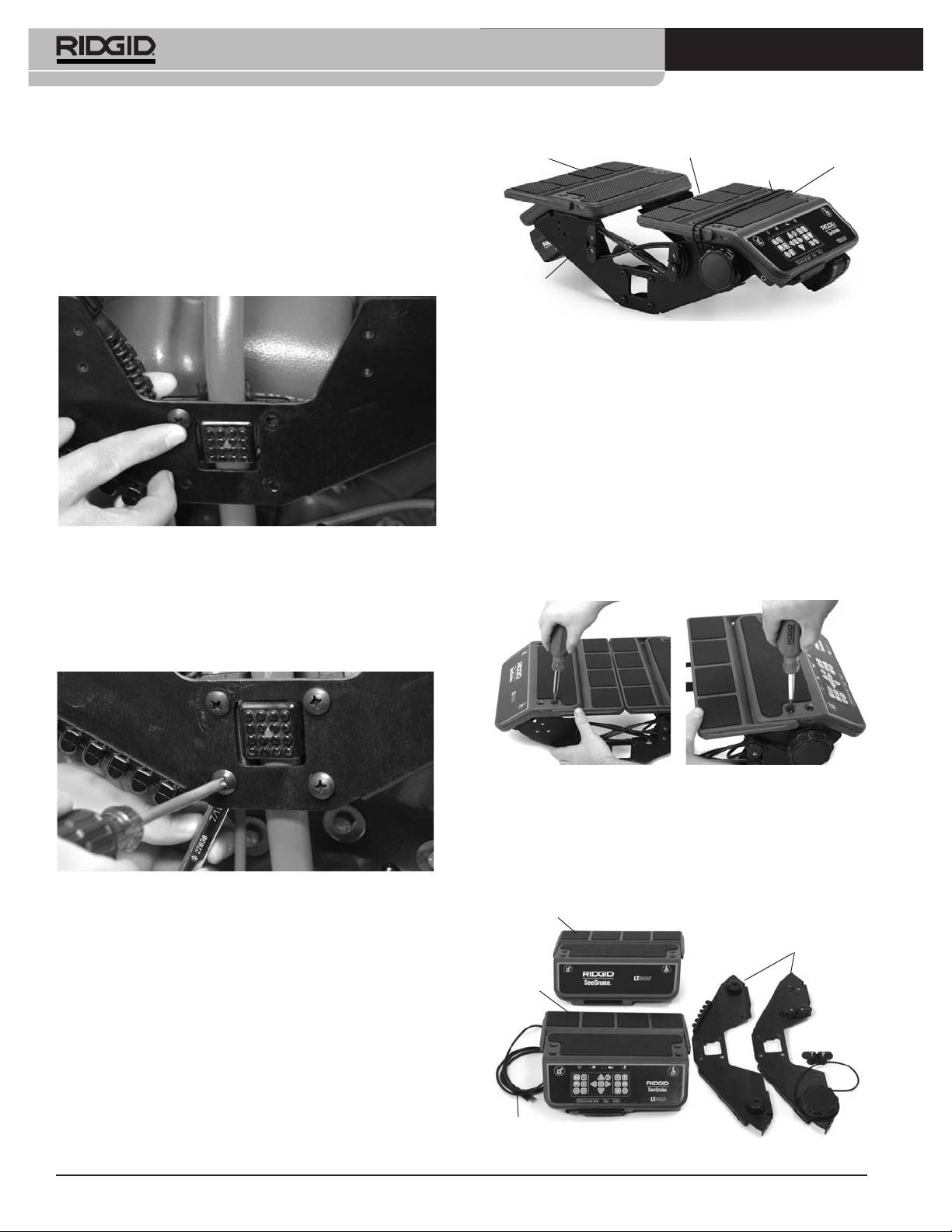
®
SeeSnake
LT1000
3. Les parties recourbées des supports du Mini
Plate-forme
Rallonges
Cordon
Plate-forme
gauche
dʼarrimage
droite
SeeSnake sont orientées vers lʼintérieur. Positionnez
de portable
la LT1000 en engageant lʼorifice de sa flasque sur le
ʻpiedʼ du cadre dʼenrouleur SeeSnake, puis tenez-la
dans cette position pendant que vous engagez les vis
de fixation sur un côté de la LT1000. Le SeeSnake
peut être couché sur son dos afin de faciliter
lʼinstallation de la flasque frontale.
Enrouleur de
câble USB
Figure 7 – Déploiement des flasques de plate-forme
Montage de la LT1000 sur enrouleur
SeeSnake Standard
Le montage de la LT1000 sur enrouleur SeeSnake
Standard nécessite le retrait de ses deux plates-formes de
support de portable et de son enrouleur de câble USB.
1. A lʼaide dʼun tournevis cruciforme, retirez les deux
vis de fixation de lʼenrouleur de câble USB qui se
trouvent sur le flanc droit de la LT1000, voire du côté
dʼoù sort le câble USB. Déroulez le câble USB de
Figure 5 – Première vis de fixation
lʼenrouleur.
2. Retirez les quatre vis de fixation de chaque plate-
4. Avec une des vis de fixation engagée (mais non ser-
forme.
rée) en position, alignez le côté opposé et engagez
les quatre vis de fixation correspondantes. Les têtes
de vis doivent se trouver sur la face extérieure de la
LT1000 et les écrous du côté intérieur.
Figure 8 – Retrait des vis de fixation des plates-formes
3. Retirez les deux plates-formes et posez-les à côté de
lʼenrouleur SeeSnake. Conservez précieusement les
vis de fixation.
4. Les deux flasques latérales ainsi libérées des plates-
Figure 6 – Serrage des vis
formes peuvent alors être montées individuellement.
5. Alignez et nivelez la LT1000 puis serrez les quatre vis
Plate-forme
gauche
de fixation de chaque côté à la main. Lorsque les des
Flasques
deux flasques sont repliées, il devrait y avoir un vide
dʼenviron 1" / 2,5 cm entre celles-ci et lʼenrouleur.
Plate-forme
Serrez les quatre vis de fixation de chaque côté à
droite
lʼaide dʼun tournevis cruciforme.
6. Tournez la molette du cabestan en sens horaire afin
de libérer le cordon dʼarrimage de portable, puis
décrochez-le du côté opposé.
7. Repliez les deux flasques de la plate-forme vers le
centre
Câble USB
Figure 9 – Composants de la LT1000
26

®
SeeSnake
LT1000
5. Positionnez la flasque frontale sous la poignée
Fiche USB
Collier de
verrouillage
supérieure du SeeSnake Standard. Faites attention
de ne pas lʼégratigner en la frottant contre lʼenrouleur.
Bossage
6. Positionnez la bride de fixation sur la butée extérieure
du SeeSnake, puis alignez les trous de la flasque sur
ceux de la bride.
Figure 12 – Raccordement du câble de connexion SeeSnake
AVIS IMPORTANT
Lors de la connexion ou déconnex-
ion du câble SeeSnake, ne tournez que le collier de ver-
rouillage afin de ne pas endommager sa fiche.
Figure 10 – Alignement de la bride et de la flasque
7. Introduisez les quatre vis à travers la bride de fixation
et la flasque, puis engagez les écrous correspon-
dants en les serrant à la main.
Figure 13 – Montage de la plate-forme droite
10. Montez la plate-forme droite (celle comprenant le
Figure 11 – Flasque côté intérieur montée
clavier) en lʼalignant sur les trous de fixation prévus
dans les flasques, puis introduisez les vis de fixation
8. Répétez le processus pour monter la flasque et la
et serrez-les à la main tout en maintenant la plate-
bride du côté opposé. Les deux flasques devraient
forme de niveau.
alors être de niveau.
9. Amenez le câble de connexion SeeSnake entre les
flasques, puis raccordez-le à la fiche SeeSnake qui se
trouve en bas de la plate-forme droite. La fiche du
Tenon
câble de connexion est pourvue dʼun bossage per-
mettant de lʼaligner sur la broche de guidage de la
prise correspondante. Introduisez la fiche du câble de
connexion à fond dans la prise, puis tournez le collier de
verrouillage en sens horaire pour lʼarrimer.
Orifice
Figure 14 – Tenon et orifice dʼalignement
27
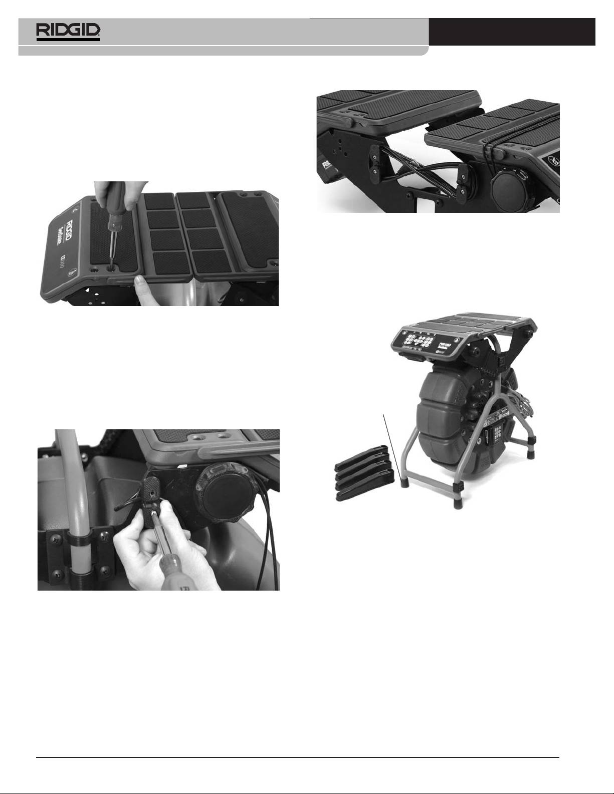
®
SeeSnake
LT1000
Chaque extrémité de chacune des plates-formes est
pourvue dʼun petit tenon dʼalignement qui doit sʼintroduire
dans lʼorifice correspondant afin dʼassurer le bon posi-
tionnement de la plate-forme.
11. Alignez la plate-forme gauche (celle qui nʼa pas de
clavier) sur les quatre trous de vis des flasques, puis
introduisez le vis de fixation et serrez-les à la main.
Figure 17 – Câble USB sur lʼenrouleur
Montage des stabilisateurs
La LT1000 est livrée avec des stabilisateurs escamota-
bles qui augmentent la stabilité de lʼenrouleur lorsquʼils
sont déployés. Chaque stabilisateur est équipé dʼune pla-
tine à ressort qui le tient en place lorsquʼil est installé.
Figure 15 – Montage de la plate-forme gauche
12. Réglez les plates-formes et les flasques de manière
à niveler et aligner les plates-formes, puis serrez les
vis de fixation des plates-formes de portable et celles
des brides de flasque à fond.
13. Remontez lʼenrouleur du câble USB à lʼaide des
deux vis prévues. A noter que le câble USB doit
Patin en
passer derrière lʼentretoise de lʼenrouleur à sa sortie
caoutchouc
de la LT1000.
Figure 18 – Stabilisateurs sur enrouleur Mini
Pour monter les stabilisateurs :
1. Retirez le patin en caoutchouc dʼun des béquilles
de lʼenrouleur.
2. Engagez le stabilisateur sur la béquille, partie pleine
Figure 16 – Remontage de lʼenrouleur de câble USB avec le
vers le haut.
câble USB passant derrière lʼentretoise de
lʼenrouleur
3. Remboîtez le patin en caoutchouc.
4. Répétez le processus sur les béquilles restantes.
Sur les gros enrouleurs Standard, les stabilisateurs ne
se montent que sur les béquilles, pas sur les jam-
bages à roue.
28
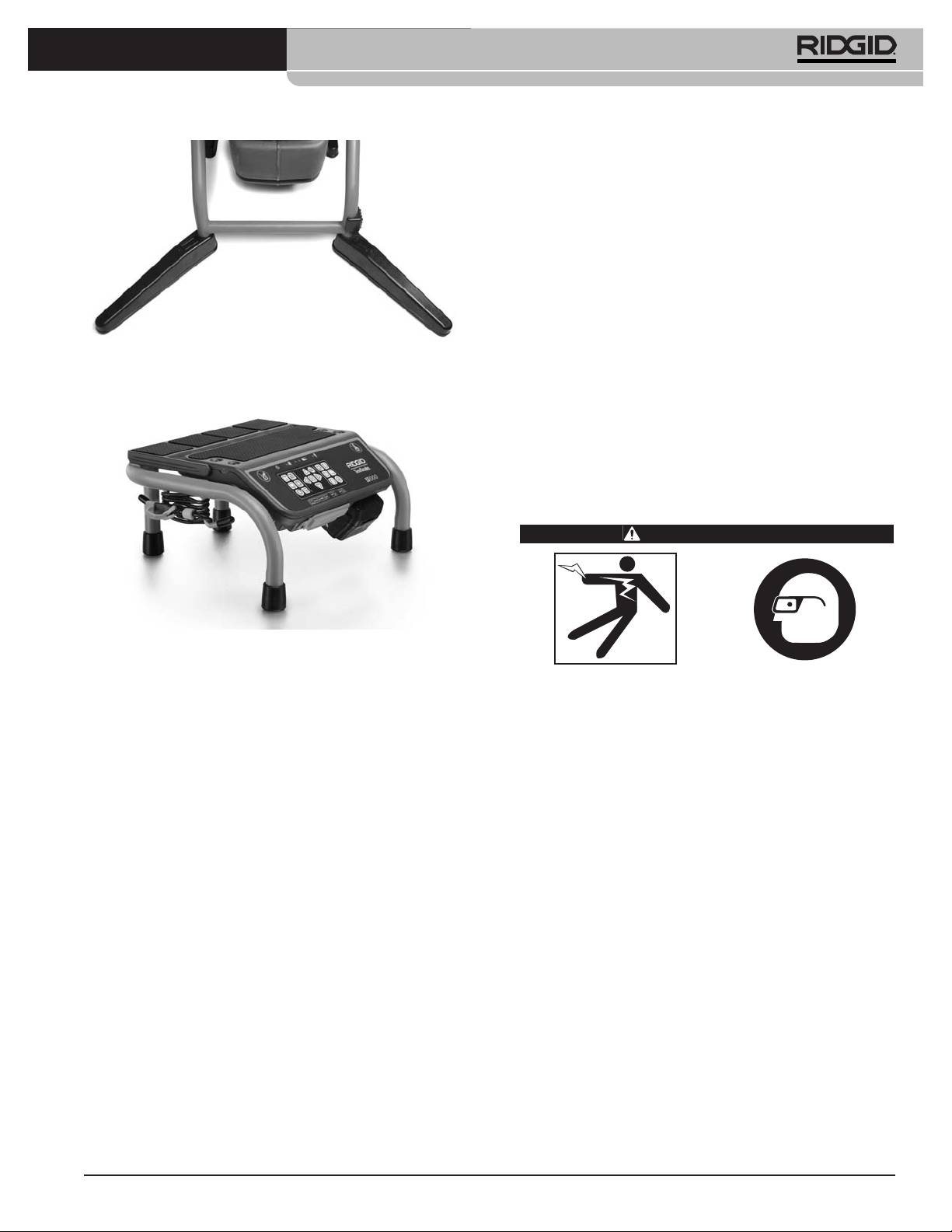
®
SeeSnake
LT1000
NOTA ! Des contrôles de mise à jour auront lieu au-
tomatiquement dès que lʼordinateur est connecté
à Internet. Si des mises à jour éventuelles sont
détectées, il vous sera demandé de confirmer
leur téléchargement, et le cas échéant, celui-ci se
fera automatiquement. La dernière mise à jour du
logiciel peut être vérifiée au lien suivant :
http://www.hq.ridgid.com/product-hq.php .
4. Il est également possible de télécharger le logiciel en
suivant les instructions du lien ci-dessus.
Figure 19 – Stabilisateurs installés
5. Pour obtenir des instructions détaillées visant
lʼutilisation du logiciel HQ pour la gestion de vos
LT1000 Mini
vidéos, images, rapports, comptes client et formats,
allez à http://www.hq.ridgid.com/. YVous y trouverez
des instructions en ligne couvrant lʼensemble des
capacités du logiciel HQ.
Inspection préalable
AVERTISSEMENT
Figure 20 – LT1000 Mini
La LT1000 Mini, montée sur un support indépendant ro-
Inspectez la LT1000 avant chaque utilisation afin de
buste et portable, se raccorde à tout enrouleur SeeSnake
corriger toute anomalie éventuelle pouvant en-
par le biais dʼun câble de connexion SeeSnake. Cʼest la
traîner des blessures graves (choc électrique, etc.)
parfaite solution économique lorsquʼil sʼagit de fréquem-
ou endommager le matériel.
ment transférer une LT1000 dʼun enrouleur SeeSnake à
un autre. La LT1000 Mini est livré avec la LT1000 déjà in-
1. Assurez-vous que lʼappareil est hors tension, que
stallée sur son cadre portable.
toute source dʼalimentation externe est déconnectée
et que la pile a été retirée. Examinez les cordons
Préparation du portable
dʼalimentation ainsi que le câble de connexion et
ses fiches pour signes dʼanomalie.
Pour quʼun portable fonctionne correctement avec la
LT1000, il doit être équipé du logiciel SeeSnake HQ.
2. Nettoyez la SeeSnake LT1000 soigneusement afin
dʼaméliorer la qualité dʼinspection et dʼéviter que
Le logiciel HQ vous permet de créer, gérer et sauvegarder
lʼappareil sʼéchappe dʼentre vos mains en cours
les images, les bandes sonores et les vidéos enreg-
dʼutilisation ou de transport.
istrées par la LT1000. Ce logiciel est livré avec la LT1000
sous forme de CD. Pour le télécharger :
3. Examinez la LT1000 pour signes dʼéléments brisés,
usés, manquants, mal alignés ou grippés, ainsi que
l vous faudra installer SeeSnake HQ et ses drivers avant
pour tout signe dʼanomalie qui pourrait compromettre
de connecter la LT1000 à votre ordinateur.
le bon fonctionnement et la sécurité de lʼappareil.
1. Mettez le CD dans le lecteur du portable
Assurez-vous du serrage approprié des points de fix-
ation de la LT1000.
2. Le portable devrait alors détecter le CD et lancer son
installation. Il risque de demander un mot de passe
4. Examinez lʼensemble du matériel utilisé selon les
« Administrateur » avant de procéder à lʼinstallation du
consignes des modes dʼemploi concernés afin de
logiciel HQ.
vous assurer de son bon état de fonctionnement.
3. En fin dʼinstallation, éjectez le CD et rangez-le dans
5. En cas dʼanomalie, attendez que le matériel soit ré-
un endroit sur.
paré avant de lʼutiliser.
29
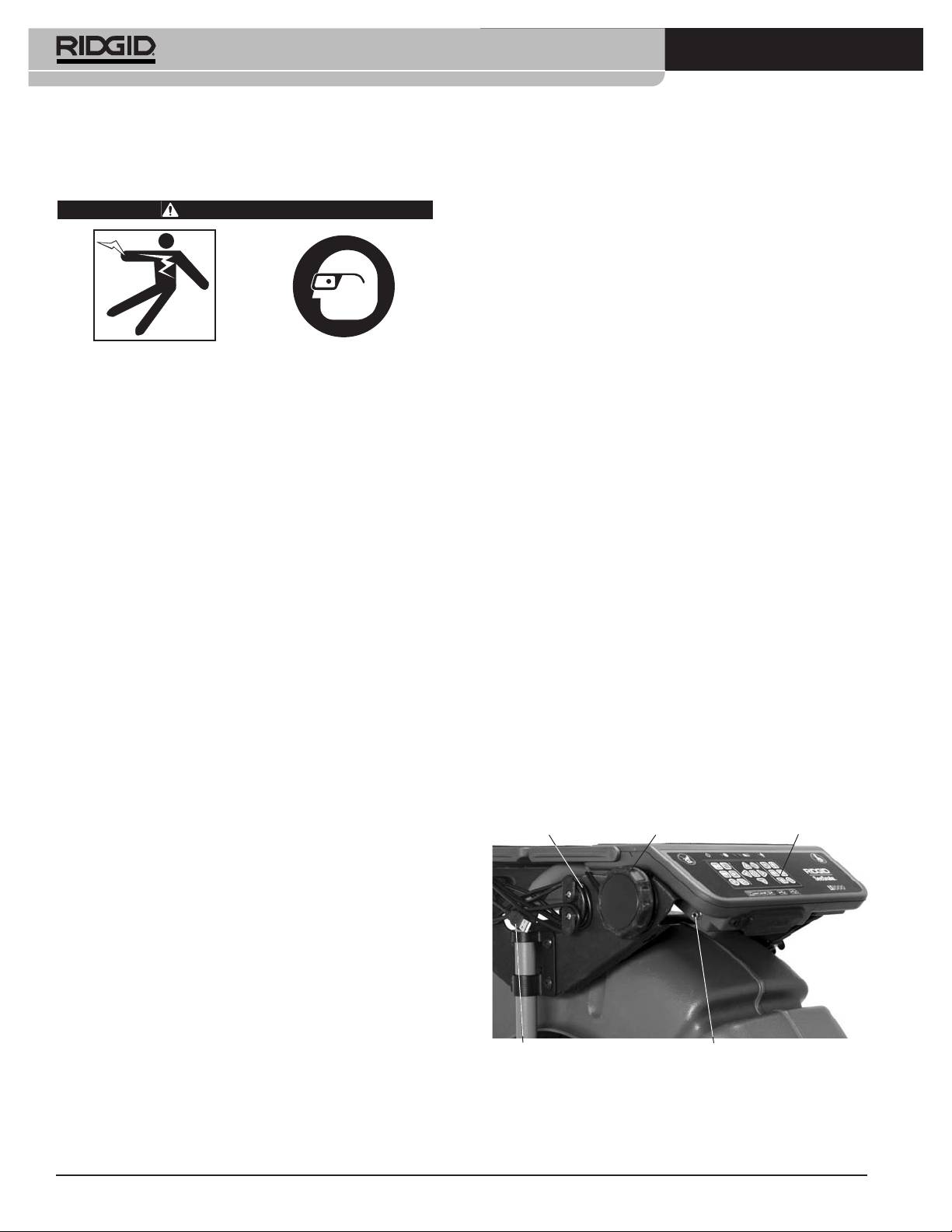
®
SeeSnake
LT1000
6. Au besoin, retirez les appareils sanitaires (cuvettes de
Préparation des lieux et du
WC, lavabos, etc.) pour raisons dʼaccès.
matériel
Positionnement de la LT1000
AVERTISSEMENT
Une fois sur le chantier, positionnez lʼenrouleur SeeSnake
avant dʼy installer le portable sur la LT1000. Pour ac-
céder aux poignées de manutention de lʼenrouleur
SeeSnake, repliez les rallonges de plate-forme de chaque
côté de la LT1000. Le cordon dʼarrimage du portable peut
être passé sous la plate-forme et accroché à ses cro-
chets durant le transport.
Installez la LT1000 et le chantier selon les con-
signes suivantes afin de protéger l’appareil et limiter
Positionnez lʼenrouleur et la LT1000 de manière à ce que
les risques de choc électrique, d’incendie et autres
cette dernière reste accessible et visible pendant la ma-
accidents potentiels.
nipulation de la caméra et du câble durant lʼinspection.
1. Faites une reconnaissance des lieux pour garantir :
Assurez-vous que la LT1000 et le reste du matériel ne ris-
queront pas dʼêtre mouillés en cours dʼutilisation. La
• La présence dʼun éclairage suffisant
LT1000 nʼest pas étanche et risque dʼêtre endommagée ou
• Lʼabsence de produits inflammables (que ce soit
provoquer des chocs électriques si elle se mouille.
sous forme de liquide, gaz ou poussière). En
présence de tels combustibles, ne pas travailler
Montage du portable
dans les locaux avant dʼen avoir identifié et élim-
iné la source. Dans la mesure où la LT1000 nʼest
1. Desserrez le cordon dʼarrimage en tournant le
pas blindée, ses connexions électriques peuvent
cabestan en sens horaire.
éventuellement créer des étincelles.
2. Positionnez le portable bien dʼéquerre sur la plate-
• Un emplacement dégagé, de niveau, stable et sec
forme avec son clavier du même côté que celui de la
pour lʼutilisateur. Ne pas utiliser ce matériel lorsque
LT1000.
vous avez les pieds dans lʼeau.
3. Faites passer le cordon dʼarrimage élastique à travers
• Lors de lʼutilisation dʼune source dʼalimentation ex-
du portable de façon à ne pas gêner son clavier.
terne, un passage sans encombre et sans danger
jusquʼà la prise de courant pour le cordon
4. Tournez le cabestan en sens anti-horaire jusquʼà
dʼalimentation.
bien serrer le cordon dʼarrimage.
2. Examinez le chantier. Dans la mesure du possible,
5. Amenez le câble USB de la LT1000 jusquʼau portable
déterminez ses points dʼaccès, sa section, sa
et branchez-le sur la prise USB correspondante. Le
longueur et lʼéventuelle présence de produits chim-
cas échéant, enroulez le restant du câble sur les en-
iques. En présence de produits chimiques, il con-
rouleurs de câble USB comme indiqué à la Figure 7.
viendra de se familiariser avec les mesures de
Cordon dʼarrimage
Molette du cabestan
Clavier
sécurité applicables en consultant le fabricant des dits
produits.
3. Déterminez le matériel nécessaire en fonction des
travaux envisagés. La LT1000 sert à visualiser les in-
spections effectuées par caméra dʼinspection. Les ap-
pareils adaptés à dʼautres types dʼinspection se
trouvent sur le catalogue Ridge Tool et sur les sites
www.RIDGID.com et www.RIDGID.eu.
4. Effectuez une inspection préalable de lʼensemble du
matériel.
Câble USB
Borne du transmetteur
5. Examinez les lieux afin de déterminer sʼil est néces-
saire dʼériger des barricades pour garder les specta-
Figure 21 – Clavier, cabestan et câble USB
teurs à lʼécart. Les spectateurs peuvent distraire
lʼopérateur de son travail. Lors des travaux à proxim-
A noter que dans les endroits restreints ou sur les surfaces
ité de circulation routière, posez de cônes ou autres
inclinées (toitures, etc.), il sera parfois préférable de
barrières pour avertir les automobilistes.
coucher le SeeSnake sur son flanc, de dérouler le câble
30
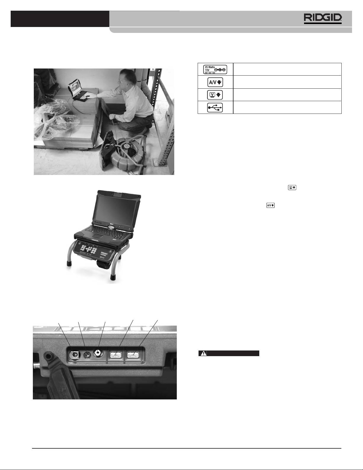
®
SeeSnake
LT1000
USB venant du portable, et de placer ce dernier dans un
Branchements
endroit plus sécurisé.
Prise dʼalimentation sur secteur
Sortie audiovisuelle (DVDR externe, etc.)
Sortie vidéo (moniteur externe)
Port USB (clés USB, etc.)
Les ports USB peuvent éventuellement servir à brancher
un clavier externe.
La sortie audiovisuelle en façade peut fonctionner même
lorsque HQ ne sert pas.
Utilisation de moniteurs externes
1. La LT1000 peut être raccordée à un moniteur
SeeSnake en branchant un câble RCA venant de sa
Figure 22 – Configuration alternative en cas de restreintes
prise « Video IN » (arrivée vidéo) sur la prise « Video
OUT » (sortie vidéo) marquée qui se trouve au
dos de la LT1000.
2. La sortie audiovisuelle permet de faire passer en
temps réel les vidéos émises par une caméra
SeeSnake connectée à la LT1000, en même temps
que les émissions sonores venant du microphone,
vers un DVDR ou moniteur. A noter quʼune connex-
ion avec un moniteur équipé de haut-parleurs risque
de créer des parasites qui peuvent être éliminés en
baissant le volume du moniteur ou du DVDR.
La connexion USB de la LT1000 ne peut fonctionner
que lorsquʼelle est raccordée à un dispositif utilisant
SeeSnake HQ.
Figure 23 – Portable sur LT1000 Mini
Alimentation de la SeeSnake LT1000
La SeeSnake LT1000 peut être alimentée soit par pile
Raccordement de la LT1000
RIDGID Li-ion rechargeable, soit sur secteur à lʼaide
Alimentation
Sortie audio-
Sortie
du convertisseur de courant fourni. A noter que
USB
sur secteur
visuelle
vidéo
USB
lʼalimentation par pile est la méthode préférée, car elle
limite les risques de choc électrique. De surcroît, le con-
vertisseur de courant nʼest pas étanche et ne doit
être utilisé quʼà lʼintérieur.
AVERTISSEMENT
Afin de limiter les risques de
choc électrique, nʼutilisez que des piles ou une source
dʼalimentation isolée pour alimenter la LT1000 et tout
portable associé.
Alimentation par pile
Avec les mains sèches, introduisez une pile 18V chargée
dans le logement de pile qui se trouve sous le côté
Figure 24 – Prises de la LT1000
droit du clavier. Une pile de rechange peut être égale-
ment stockée dans le logement de pile de rechange
qui se trouve sous lʼextrémité opposée de la LT1000. Ce
logement est dépourvu de connexions électriques et
ne sert que de rangement.
31
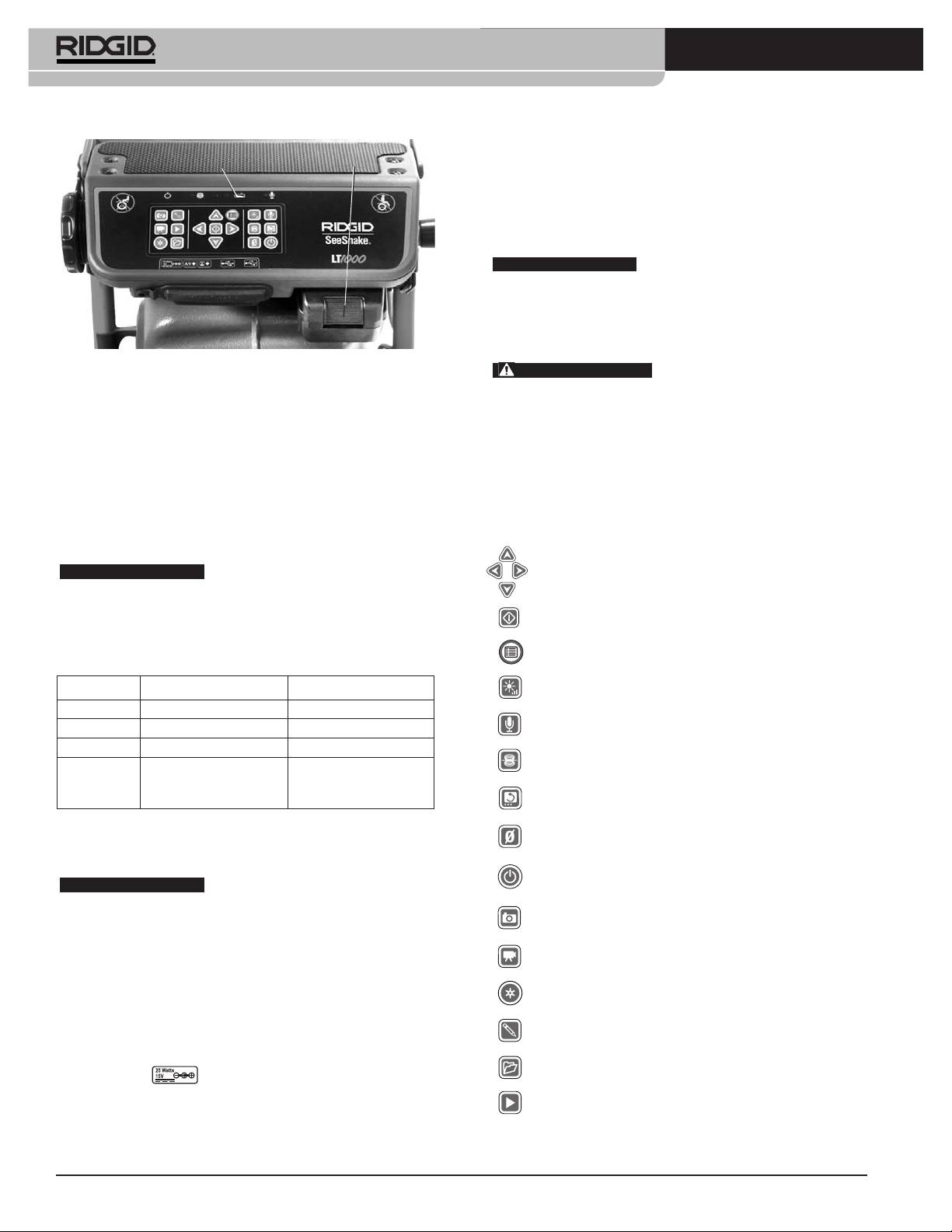
®
SeeSnake
LT1000
Niveau de
long dʼun passage dégagé. Lors de lʼutilisation dʼune rallonge
charge
Pile
Pile
électrique, assurez-vous que celle-ci est de section suffisante. Par
exemple, une rallonge de 25 pieds / 7,5 m de long doit avoir une
2
section de conducteurs minimale de 18 AWG / 0,8 mm
, tandis
quʼune rallonge de plus de 25 pieds / 7,5 m doit avoir une sec-
2
tion minimale de 16 AWG / 1,5 mm
.
AVIS IMPORTANT
Si la source dʼalimentation sur secteur
nʼest pas fiable et produit des crêtes de tension transitoire, la vidéo
enregistrée par la LT1000 risque de geler. Le cas échéant, il sʼagit
simplement dʼéteindre puis de rallumer la LT1000 pour la re-
lancer. Les données enregistrées ne seront pas perdues, mais
le compteur de distance risque de se remettre à zéro.
Figure 25 – Connexions de la LT1000
AVERTISSEMENT
Si le portable utilisé est alimenté
par un convertisseur non isolé, une inversion terre/phase pour-
Sʼassurer que la pile sʼengage bien sur les bornes du chargeur.
rait endommager le portable via la connexion de mise à la
Consultez le mode dʼemploi du chargeur pour de plus amples
terre du câble USB.
renseignements.
Utilisez exclusivement une pile ou un convertisseur isolé pour al-
Les piles fournies pour le LT1000 ont une capacité nominale de
imenter la LT1000 et tout portable associé.
2.2Ah / 2,2Ah. Lorsque complètement chargées, elles assurent
à la LT1000 une autonomie de 2.5 / 2,5 à 3 heures selon son util-
Commandes de la LT1000
isation (enregistrement, etc.). Des témoins de charge LED en
partie haute du clavier indiquent le niveau de charge de la pile (se
Touches du clavier
reporter au tableau des témoins de charge LED).
Flèches – Navigation du menu, sélection des paramètres et
AVIS IMPORTANT
Eteignez la LT1000 avant de rem-
rotation dʼimage.
placer ou retirer sa pile. Le fait de retirer la pile pendant que
lʼappareil est en marche risque de faire perdre les enreg-
Sélection – Choix des unités de valeur (auto, mètres, pieds)
istrements faits par la caméra.
à partir du menu Unités.
Menu – Affichage des paramètres (couleur, luminosité,
Tableau des LED de charge
contraste, unités de valeur, etc.).
Luminosité – Augmentation ou diminution de la luminosité
Charge Secteur débranché Secteur branché
des LED de la caméra.
Complète Témoin Vert Témoins LED éteints
Sourdine – Mise en sourdine ou activation du microphone en
Médiane Témoins vert et rouge Témoins LED éteints
cours dʼinspection pour ajouter des commentaires.
Faible Témoin rouge, 4 bips Témoins LED éteints
Sonde – Activation de la sonde incorporée en vue de
Zéro Témoin rouge pendant Témoins LED éteints
localiser la tête de caméra.
5 secondes, bip
prolongé puis arrêt
*Rotation – Rotation verticale de lʼimage affichée à lʼécran.
Alimentation sur secteur
Zéro – Remise à zéro temporaire du compteur de distance
Un convertisseur de courant à double isolation est prévu pour
des appareils équipés du système CountPlus.
convertir la tension du secteur à celle utilisable par la LT1000.
Marche/Arrêt – Allumer et éteindre la LT1000.
AVIS IMPORTANT
Lʼappareil ne doit être branché sur
secteur quʼà lʼintérieur.
*Photo – Prises de clichés par la caméra.
Pour alimenter le système à lʼaide du cordon dʼalimentation,
repérez lʼalimentation. Le cordon dʼalimentation est composé de
*Vidéo – Lance ou arrête les enregistrements vidéo et
audio.
deux parties, dʼun côté une partie qui se branche sur une prise 110
-120V standard à deux lames (modèle pour les Etats-Unis) ou une
*Autolog – Répertoriage automatique dʼune série de
clichés stockés du chantier en cours.
prise 230V standard à deux broches (modèle pour lʼUnion
Européenne), et de lʼautre côté une partie qui se branche sur
*Onglet photo – Création dʼun nouveau cliché avec anno-
lʼalimentation. Pour alimenter le système sur secteur, Branchez,
tations éventuelles.
avec les mains sèches, la fiche ronde du convertisseur dans la
*Gestionnaire – Accès à un menu dʼoptions de gestion des
prise marquée qui se trouve au dos de la LT1000, à
chantiers et rapports.
lʼextrémité gauche du groupe de connexions (Figure 24).
*Lecture – Relecture dʼun enregistrement en cours
éventuel.
Ensuite, et toujours avec les mains sèches, branchez la fiche
*Certaines des commandes nʼauront dʼeffet que lorsque le logiciel
électrique à deux barrettes du convertisseur sur une prise de
HQ est activé.
courant compatible en faisant attention de router son cordon le
32
®
SeeSnake
LT1000
Le logiciel HQ
ciel HQ. Sinon, il sera nécessaire de double cliquer
sur le raccourci HQ de lʼécran pour lʼactiver.
Le logiciel HQ permet de créer, de gérer et de stocker les
clichés, les enregistrements audio et les vidéos générés
5. Un nouveau chantier sera lancé par défaut, affichant
par la LT1000. Le logiciel HQ permet en outre de créer
lʼimage envoyée par la tête de caméra.
des rapports rapidement et automatiquement en vue de
6. Pour des instructions plus détaillées, reportez-vous
les envoyer au client par mail, voire de les enregistrer en
aux fichiers dʼaide du logiciel HQ qui se trouvent sur
format HTML pour les remettre en main propre sur clé
le lien : http//www.hq.ridgid.com/.
USB ou sur DVD. La plate-forme HQ facilite également la
gestion et le stockage des fichiers de chantier pour future
Inspection des conduites
référence éventuelle.
1. Si elle est éteinte, allumez la LT1000.
Le logiciel HQ est décrit dans tous ses détails au sein des
fichiers dʼaide HQ qui se trouvent sur le lien suivant :
2. Introduisez la tête de caméra dans la conduite et, le
http://www.hq.ridgid.com/.
cas échéant, remettez le compteur à zéro.
3. Procédez à lʼinspection suivant les instructions du
manuel SeeSnake concerné.
Consignes d’utilisation
AVERTISSEMENT
Réglage de luminosité
En fonction des conditions rencontrées, il est parfois
nécessaire de moduler la luminosité de lʼéclairage LED
de la caméra en cours dʼinspection. Pour ce faire, ap-
puyez sur la touche « Luminosité » , puis sur les
flèches ou pour lʼaugmenter
ou la décroître. Appuyez sur la touche « Menu » une fois
terminé.
Prévoyez systématiquement des lunettes de sécu-
rité afin de protéger vos yeux contre la projection de
Rotation dʼimage
débris.
Il arrive que la caméra se retourne sur son dos en
Lors de l’inspection des conduites d’évacuation
cours dʼinspection, laissant ainsi une image inversée. La
susceptibles de renfermer des produits chimiques
touche « Rotation » permet dʼinverser lʼimage af-
ou des bactéries, prévoyez les équipements de pro-
fichée à lʼécran pour en faciliter la lecture. Le logiciel HQ
tection individuelle appropriés, tels que gants en
permet en outre de corriger lʼaplomb de lʼimage par
latex, lunettes étanches, visières et respirateurs afin
de limiter les risques de brûlure et d’infection.
degrés.
Ne pas utiliser ce matériel si l’appareil ou son util-
Remise à zéro temporaire
isateur a les pieds dans l’eau. La présence d’eau
Si lʼenrouleur utilisé est équipé dʼun compteur de dis-
augmenterait les risques de choc électrique. Des
chaussures antidérapantes à semelle en caoutchouc
tance CountPlus, le parcours mesuré sʼaffichera à
peuvent aider à éviter les dérapages et les chocs
lʼécran. Pour établir une distance partielle entre deux
électriques, notamment sur les surfaces mouillées.
points dʼintérêt (piquage, dérivation, etc.), appuyez sur
Respectez les consignes d’utilisation ci-après afin de
la touche « Zéro » , et la distance correspondante
limiter les risques de blessure par choc électrique,
sera affichée entre parenthèses carrées [0,0]. Reportez-
entre autres.
vous au manuel du CountPlus pour plus de détails.
Les paramètres du système CountPlus (date, heure, etc.)
Mise en route
sont gérés à partir de la touche « Menu CountPlus »
1. Assurez-vous que lʼappareil est correctement installé.
qui donne accès aux « Outils CountPlus ». Les textes su-
perposés du CountPlus sont gérés au niveau du clavier
2. Assurez-vous que le portable est en place, correcte-
CountPlus comme indiqué dans le manuel CountPlus.
ment raccordé et équipé du logiciel HQ. Allumez le
portable.
Localisation de la caméra à l’aide de la
3. Introduisez la tête de caméra dans lʼanneau de
sonde
guidage de lʼenrouleur et allumez la LT1000 .
De nombreux systèmes dʼinspection SeeSnake sont
équipés dʼune sonde incorporée qui transmet un signal
4. Normalement, lorsque la LT1000 est allumée, le
repérable sur 512Hz. Lorsque la sonde est activée, un lo-
portable détecte le dispositif SeeSnake et lance le logi-
calisateur tel que le RIDGID SR-20, SR-60, Scout™ ou
33
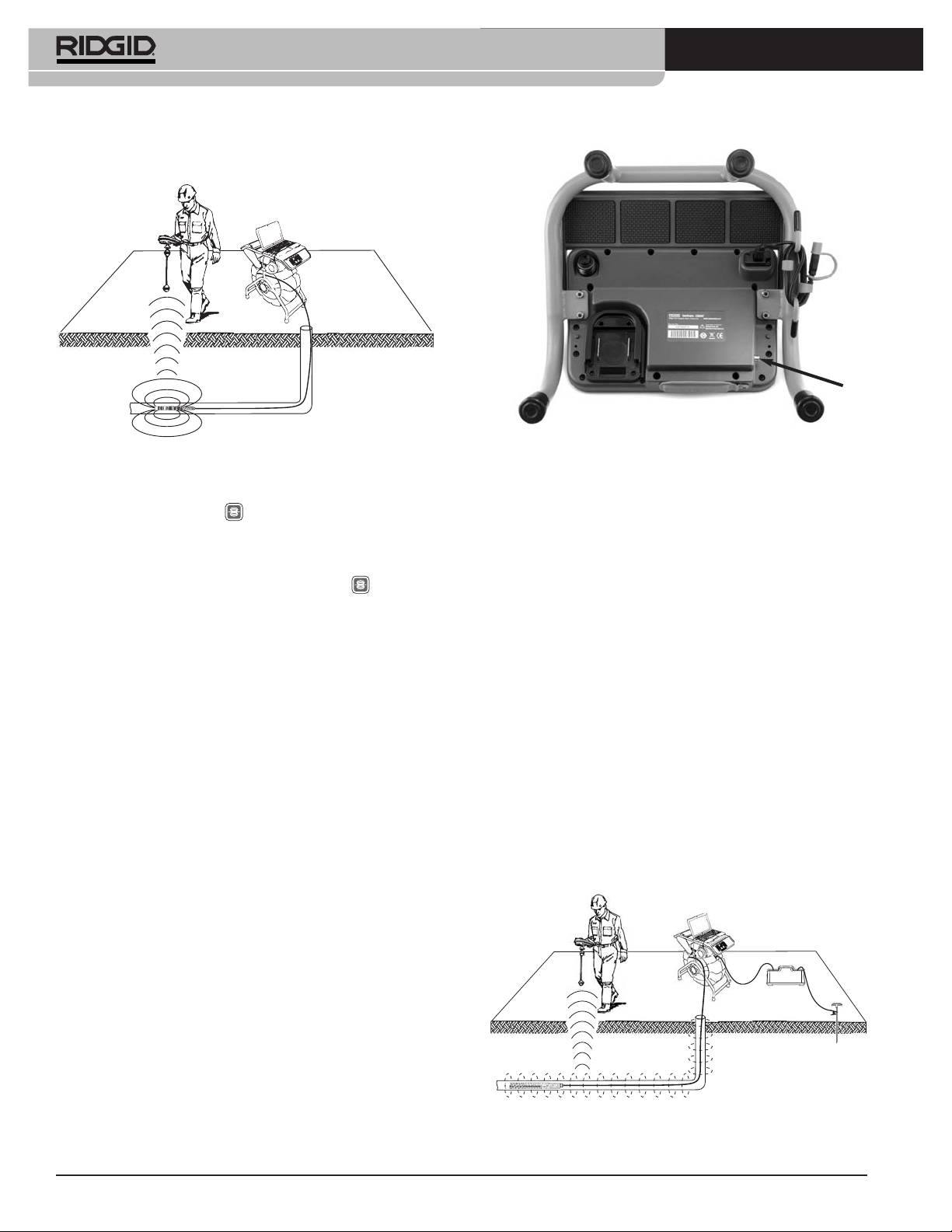
®
SeeSnake
LT1000
®
NaviTrack
II réglé à 512Hz pourra la détecter et vous per-
mettre de localiser la position de la caméra sous terre.
Borne de transmetteur
Figure 27 – Borne de transmetteur de la LT1000
Figure 26 – Localisation de la sonde
Après avoir réglé le transmetteur et le localisateur à la
Pour activer la sonde à partir de la LT1000, appuyez
même fréquence (33kHz ou autre), servez-vous du lo-
sur la touche « Sonde » . Lʼicône de la sonde restera
calisateur pour tracer la conduite (Figure 28). La sonde de
affiché à lʼécran tant quʼelle est activée. Lʼactivation de la
512Hz incorporée de la caméra peut être activée en
sonde peut éventuellement créer des parasites, mais
même temps, et si votre localisateur est équipé dʼun dis-
ceux-ci disparaîtront dès quʼelle est désactivée en ap-
positif SimulTrace™ à double fréquence, il pourra dʼabord
puyant à nouveau sur la touche « Sonde » .
suivre le câble jusquʼà la caméra, puis détecter la sonde
de la caméra lorsque vous arrivez sensiblement à lʼaplomb
Le moyen le plus pratique de suivre la sonde est
de celle-ci.
dʼenvoyer le câble dans la conduite sur une distance de 5
ou 10 pieds / de 1,5 ou 3 mètres, puis de se servir du lo-
A défaut du dispositif SimulTrace™, vous pouvez utiliser
calisateur pour repérer sa position. En suite, vous pouvez
un ensemble transmetteur/localisateur pour suivre le
faire avancer le câble sur une distance semblable afin de
câble. Lorsque le signal sʼaffaiblit, passez le localisateur en
localiser la sonde à nouveau en partant de sa position
mode « Sonde » en utilisant la fréquence de la sonde
précédente. Pour localiser la sonde, allumez le localisa-
(voire typiquement 512Hz). Reprenez le signal à partir du
teur et mettez-le en mode « Sonde ». Balayez le tracé an-
point où la fréquence de traçage a commencé à faiblir,
ticipé jusquʼà ce que le localisateur détecte la sonde.
puis ciblez la sonde. Dans la mesure où la localisation de
Une fois la sonde repérée, servez-vous des indications du
fréquences émises par un transmetteur risque de parasiter
localisateur pour préciser sa position. Consultez le mode
lʼimage affichée à lʼécran, il est préférable dʼéteindre la
dʼemploi du localisateur utilisé pour de plus amples pré-
sonde et les transmetteurs durant lʼinspection dʼune con-
cisions sur la localisation des sondes.
duite, pour ne les rallumer que lorsquʼil est nécessaire
dʼeffectuer une localisation.
Suivre le câble SeeSnake
La LT1000 permet également de suivre le tracé souterrain
du câble à lʼaide dʼun localisateur RIDGID standard tel que
®
le NaviTrack
II, le Scout™, le SR-20 ou le SR-60. Pour ce
faire, il sʼagit simplement de pincer lʼun des deux câbles du
transmetteur sur un piquet de terre approprié, et lʼautre sur
la borne de transmetteur de la LT1000. La borne de
transmetteur est un tenon métallique situé sous le côté
gauche du clavier comme indiqué à la Figure 27.
Figure 28 – Suivi du câble
34
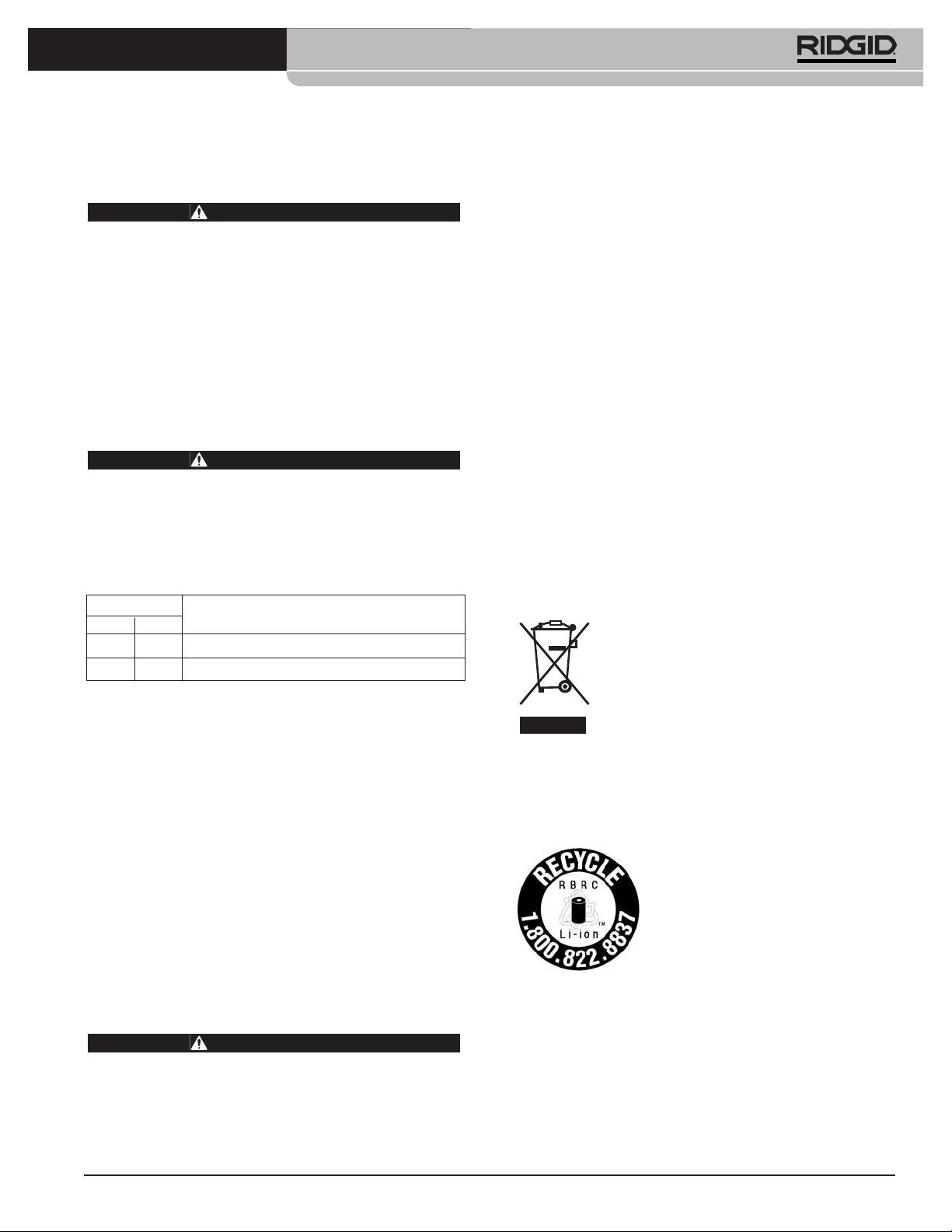
®
SeeSnake
LT1000
Consignes d’entretien
Pour obtenir les coordonnées du centre de service
RIDGID le plus proche ou pour toutes questions visant
Nettoyage
lʼentretien et la réparation de lʼappareil :
AVERTISSEMENT
• Consultez votre distributeur RIDGID.
Vérifiez que l’ensemble des cordons et câbles
• Consultez les sites www.RIDGID.com ou
ont été débranchés et que la pile a été retirée
www.RIDGID.eu pour localiser le représentant
avant toute intervention sur la LT1000 afin de
Ridge Tool le plus proche.
limiter les risques de choc électrique.
• Consultez les services techniques de Ridge Tool par
Ne jamais utiliser de produits de nettoyage liquides ou
mail adressé à rtctechservices@emerson.com, et à
abrasifs sur la LT1000. Nettoyez-la à lʼaide dʼun chiffon
partir des Etats-Unis et du Canada, en composant le
humecté. Ne jamais permettre de liquides (eau ou autres)
(800)519-3456.
de sʼintroduire dans la LT1000.
Vous pouvez également contacter le service
dʼassistance SeeSnake HQ par mail adressé à :
HQSupport@seesnake.com.
Accessoires
AVERTISSEMENT
Recyclage
Les accessoires suivants sont spécifiquement des-
tinés à la LT1000. L’utilisation d’accessoires prévus
Certains composants de lʼappareil contiennent des
pour d’autres types de matériel pourrait rendre la
matières de valeur susceptibles dʼêtre recyclées. Il se peut
LT1000 dangereuse. Afin de limiter les risques
que certaines des entreprises de recyclage concernées se
d’accident grave, n’utilisez que les accessoires
trouvent localement. Disposez de ces composants selon
spécifiquement conçus et recommandés pour la
LT1000, tels que ceux indiqués ci-après.
la réglementation en vigueur. Pour de plus amples ren-
seignements, consultez votre centre de recyclage local.
Réf.
Description
A lʼattention des pays de la CE : Ne ja-
US EU
mais jeter de matériel électrique à la
32743 28218 Pile rechargeable Li-ion 18V
poubelle !
27958 32073 Chargeur
Selon la norme européenne 2002/96/EC
visant les déchets de matériel électrique et
Transport et stockage
électronique et son application vis-à-vis de la
législation nationale, tout matériel électrique
Retirez les piles de lʼappareil avant son expédition.
non utilisable doit être collecté à part et recyclé dʼune
Protégez lʼappareil contre les chocs durant son transport.
manière écologiquement responsable.
En cas de remisage long terme, lʼappareil doit être stocké
à des températures minimales et maximales de 14ºF et
158ºF / -10ºC et 70ºC.
Recyclage des piles
Rangez tout appareil électrique dans un endroit sec afin
Pour les USA et le Canada : Le
de limiter les risques de choc électrique.
label de la RBRC[tm] (Corporation
de recyclage des piles rechargeables)
Protégez lʼappareil contre les sources de chaleur exces-
apposé sur le bloc-piles indique que
sive telles que les radiateurs, les bouches de chauffage,
RIDGID sʼest déjà acquitté des frais
les cuisinières, les amplificateurs et tout autre dispositif qui
de recyclage des piles lithium-ion qui
dégage de la chaleur.
ont atteint la fin de leur vie utile.
®
RBRC™ et RIDGID
font partie de plusieurs fournisseurs
Révisions et réparations
de piles qui, aux Etats-Unis et au Canada, ont développé
des programmes de récupération et de recyclage des
AVERTISSEMENT
piles rechargeables. Les piles normales et recharge-
La sécurité d’emploi de la LT1000 dépend en grande
ables renferment non seulement des matières toxiques
partie de son entretien approprié.
pour lʼenvironnement, mais aussi des matières précieuses
qui peuvent être recyclés. Aidez à protéger
Lʼentretien et la révision de la LT1000 doivent être confiés
lʼenvironnement et à préserver nos ressources naturelles
à un centre de service RIDGID agréé.
en remettant vos piles usagées à votre détaillant ou à un
35

®
SeeSnake
LT1000
centre de service RIDGID agréé afin dʼassurer leur recy-
Pour les pays de la CE : Les piles et bloc-piles dé-
clage. Le centre de recyclage de votre localité peut aussi
fectueux ou hors service doivent être recyclés selon les
vous indiquer dʼautres points de recyclage éventuels.
dispositions de la norme européenne 2006/66/EC.
RBRC™ est une marque déposée de la Rechargeable
Battery Recycling Corporation.
Tableau 1 – Dépannage
ANOMALIE CAUSE PROBABLE REMEDE
Lʼécran nʼaffiche pas
SeeSnake hors tension.
Vérifier le branchement sur secteur ou la charge de
dʼimage vidéo venant de
la pile.
la caméra.
Appuyez sur la touche marche/arrêt de la LT1000.
Mauvaise connexion.
Vérifier la connexion entre la LT1000 et le
SeeSnake.
Vérifier lʼassise et les broches de la connexion
SeeSnake. Nettoyer si nécessaire.
Piles déchargées.
Recharger les piles ou branchez lʼappareil sur
secteur.
Clignotement du témoin
Pile 18V de la LT1000 déchargée.
Recharger ou remplacer les piles de la LT1000
de charge.
ou branchez-la sur secteur (110 - 240V AC).
Image vidéo gelée.
Défaut dʼalimentation sur secteur ou crête
Eteindre la LT1000, puis la rallumer.
de tension.
Pas dʼimage vidéo.
Si lʼordinateur ne reconnaît pas la connexion
Redémarrer lʼordinateur, éteindre et rallumer la
USB.
LT1000, fermer puis relancer HQ pour voir si cela
règle le problème.
Ne pas allumer la LT1000 avant dʼavoir allumé
NOTA : La fiche du câble USB (Figure 12) est
lʼordinateur.
sensée résister à lʼeau et donc sʼenfonce difficile-
ment. Sʼil est nécessaire de la débrancher pour une
raison quelconque, sʼassurer de lʼenfoncer à fond
lors de sa réinstallation. Sinon, le logiciel HQ risque
de ne pas reconnaître la LT1000, et il sera proba-
blement nécessaire de relancer HQ après avoir
vérifié la connexion.
36
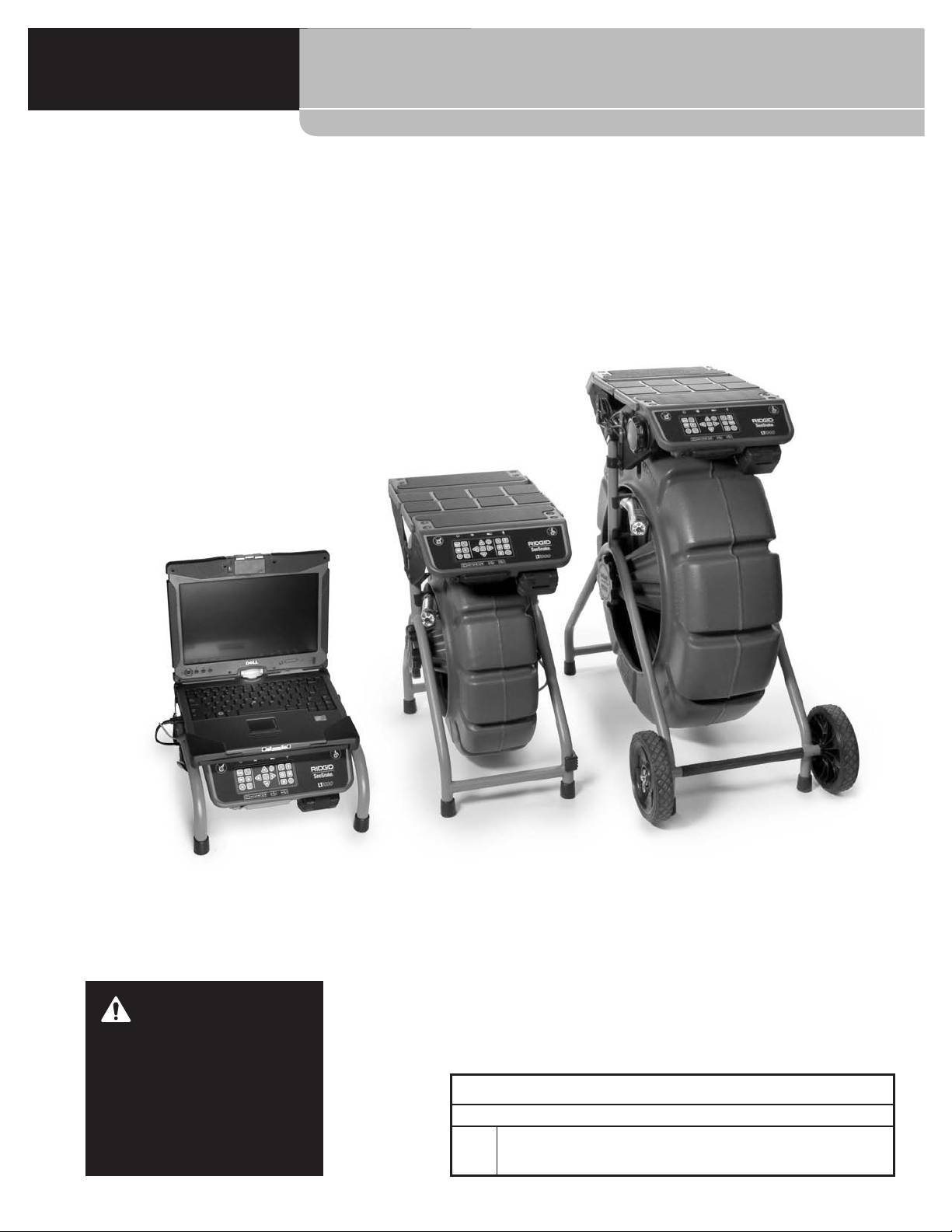
®
SeeSnake
LT1000
®
SeeSnake
LT1000
ADVERTENCIA
Antes de utilizar esta máquina, lea
su manual del operario detenida-
mente. Si no se comprenden y res-
®
SeeSnake
LT1000
petan las instrucciones de este
manual, podrían ocurrir descar-
Apunte aquí el número de serie del producto. Lo encuentra en su placa de características.
gas eléctricas, incendios y/o le-
No. de
siones personales graves.
serie

®
SeeSnake
LT1000
Índice
Ficha para apuntar el número de serie del aparato ................................................................................................37
Simbología de seguridad............................................................................................................................................39
Normas de seguridad general
Seguridad en la zona de trabajo ..............................................................................................................................39
Seguridad eléctrica ..................................................................................................................................................39
Seguridad personal ..................................................................................................................................................40
Uso y cuidado del equipo..........................................................................................................................................40
Uso y cuidado de aparatos a pila..............................................................................................................................40
Servicio ....................................................................................................................................................................41
Información de seguridad específica........................................................................................................................41
Seguridad del LT1000 ..............................................................................................................................................41
Descripción, especificaciones y equipo estándar
Descripción ..............................................................................................................................................................42
Especificaciones ......................................................................................................................................................42
Requisitos del sistema para la computadora portátil ................................................................................................42
Equipo estándar........................................................................................................................................................42
Equipo opcional ........................................................................................................................................................42
Componentes del LT1000 ..........................................................................................................................................43
Íconos ..........................................................................................................................................................................43
Ensamblaje
Montaje del LT1000 ..................................................................................................................................................43
Montaje del LT1000 sobre un rollo SeeSnake Mini ..................................................................................................43
Montaje del LT1000 sobre un rollo SeeSnake Standard ..........................................................................................44
Instalación de los estabilizadores .............................................................................................................................46
LT1000 Mini ..............................................................................................................................................................47
Preparación de la computadora portátil....................................................................................................................47
Inspección previa al funcionamiento ........................................................................................................................47
Preparación del equipo y de la zona de trabajo
Instalación del LT1000..............................................................................................................................................48
Montaje de la computadora portátil ..........................................................................................................................48
Conexión de la computadora portátil ........................................................................................................................49
Puesta en marcha del SeeSnake LT1000 ................................................................................................................50
Mandos del LT1000
Mandos en el teclado................................................................................................................................................51
Software HQ (de “headquarters” u “oficina central”) ................................................................................................51
Instrucciones de funcionamiento
Inicio..........................................................................................................................................................................51
Inspección de una tubería ........................................................................................................................................52
Ajuste de la luminosidad ........................................................................................................................................52
Rotación de la imagen ............................................................................................................................................52
Manejo del contador CountPlus..............................................................................................................................52
Localización de la cámara utilizando una Sonda......................................................................................................52
Siguiéndole la pista al cable de empuje SeeSnake dentro de la tubería..................................................................52
Mantenimiento
Limpieza....................................................................................................................................................................53
Accesorios ..................................................................................................................................................................53
Transporte y almacenamiento ..................................................................................................................................53
Servicio y reparaciones..............................................................................................................................................53
Eliminación del equipo ..............................................................................................................................................54
Eliminación de las pilas..............................................................................................................................................54
Detección de averías ..................................................................................................................................................55
Garantía vitalicia..................................................................................................................................carátula posterior
* Traducción del manual original
38
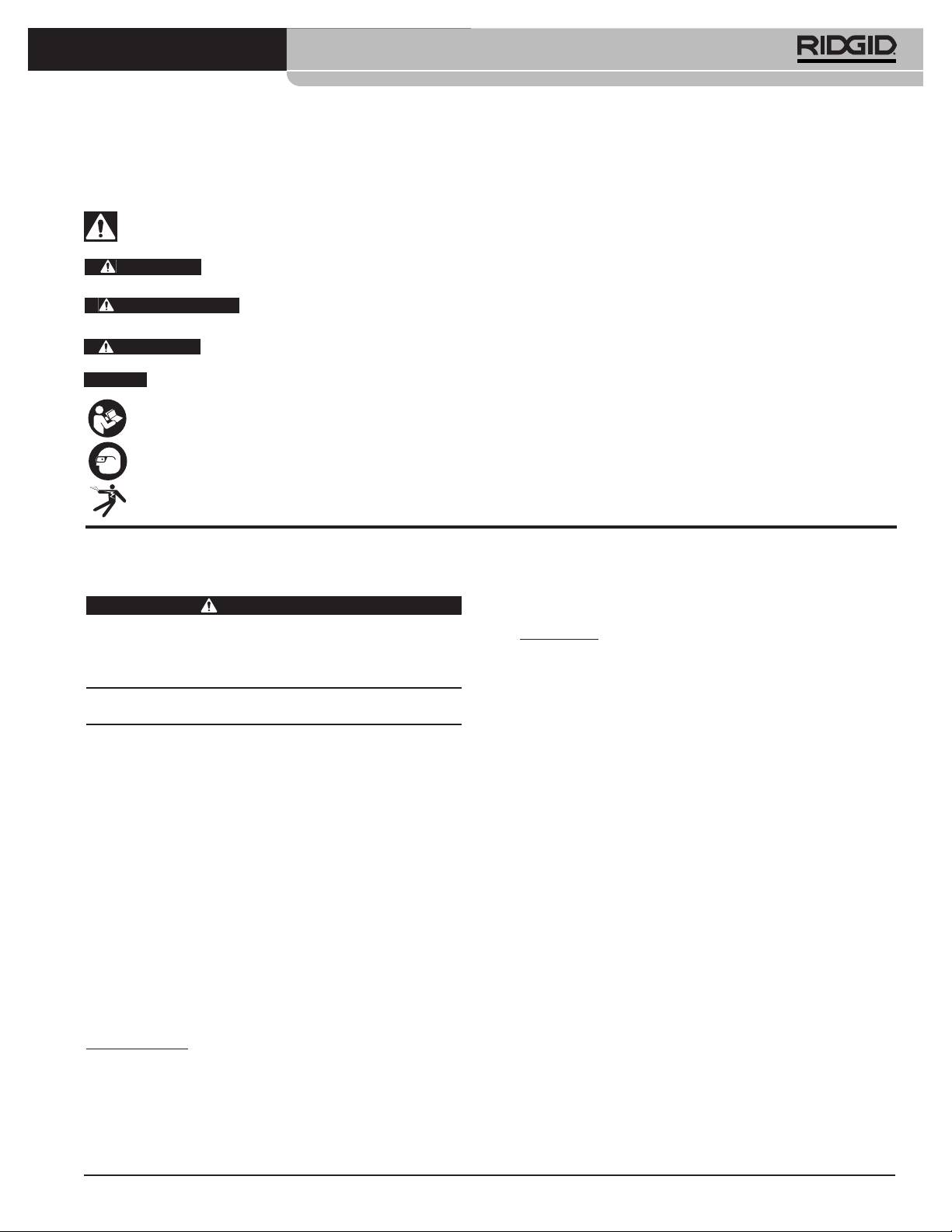
®
SeeSnake
LT1000
Simbología de seguridad
En este manual del operario y en el aparato mismo encontrará símbolos y palabras de advertencia que comunican infor-
mación de seguridad. Para su mejor comprensión, en esta sección se describe el significado de estos símbolos.
Este es el símbolo de una alerta de seguridad. Sirve para prevenir al operario de las lesiones corporales que podría sufrir. Obedezca
todas las instrucciones que acompañan a este símbolo de alerta para evitar lesiones o muertes.
Este símbolo de PELIGRO advierte de una situación de riesgo o peligro que, si no se evita, ocasionará la muerte
PELIGRO
o graves lesiones.
Este símbolo de ADVERTENCIA advierte de una situación de riesgo o peligro que, si no se evita, podría oca-
ADVERTENCIA
sionar la muerte o lesiones graves.
Este símbolo de CUIDADO previene de una situación de riesgo o peligro que, si no se evita, podría ocasionar le-
CUIDADO
siones leves o menores.
AVISO
Un AVISO advierte de que existe información referente a la protección de un bien o propiedad.
Este símbolo significa que, antes de usar el equipo, es necesario leer detenidamente su manual del operario. El manual del
aparato contiene importante información acerca del funcionamiento apropiado y seguro del equipo.
Este símbolo señala que, durante el funcionamiento de este aparato y con el fin de evitar lesiones oculares, el operario debe
llevar puestas gafas o anteojos de seguridad con viseras laterales.
Este símbolo advierte que podrían ocurrir descargas eléctricas.
entran, recurra a un electricista calificado para
Normas de seguridad general
que instale un tomacorriente polarizado. Jamás
ADVERTENCIA
modifique el enchufe de manera alguna.
Lea todas estas advertencias e instrucciones. Pueden ocu-
Modelo EU
rrir golpes eléctricos, incendios y/o lesiones corporales
graves si no se siguen todas las instrucciones y respetan las
• Las herramientas de doble aislamiento están
advertencias detalladas a continuación.
equipadas con un enchufe no polarizado de 2 patil-
¡GUARDE ESTAS INSTRUCCIONES Y ADVER-
las. El aislamiento doble elimina la necesidad de
TENCIAS PARA POSTERIOR CONSULTA!
disponer de un cordón de alimentación de tres alam-
bres con conexión a tierra como asimismo un sumin-
En la zona de trabajo
istro eléctrico conectado a tierra.
• Mantenga su zona de trabajo limpia, ordenada y
• Evite el contacto de su cuerpo con superficies
bien alumbrada. Las áreas oscuras o atestadas de
conectadas a tierra tales como cañerías, radia-
cosas provocan accidentes.
dores, estufas o cocinas y refrigeradores. Aumenta
• No haga funcionar este equipo en presencia de
el riesgo de que se produzca un choque eléctrico
combustibles tales como líquidos, gases o polvo
cuando su cuerpo ofrece conducción a tierra.
inflamables. Este aparato puede generar chispas, las
• No exponga el equipo a la lluvia, nieve o humedad.
que podrían inflamar el polvo o las emanaciones
Si al equipo le entra agua, aumenta el riesgo de que se
combustibles.
produzca una descarga eléctrica.
• Mientras haga funcionar este aparato, mantenga
• No maltrate los cordones eléctricos. Nunca trans-
apartados a niños y espectadores. Cualquier dis-
porte un aparato o equipo tomándolo de su cordón
tracción puede hacerle perder el control del aparato.
eléctrico ni lo jale para desenchufarlo del toma-
corriente. Manténgalos lejos del calor, aceite, bor-
Seguridad eléctrica
des cortantes o piezas móviles. Un cordón enredado
Modelo EEUU
o en mal estado aumenta el riesgo de que se produz-
can descargas eléctricas.
• Las herramientas con aislamiento doble están
dotadas de un enchufe polarizado (una clavija con-
• Si es inevitable poner a funcionar un equipo en un
tacto es más ancha que la otra). Este enchufe
lugar húmedo o mojado, utilice un suministro eléc-
entra en un tomacorriente de una sola manera. Si
trico dotado de GFCI (Interruptor del circuito de
los contactos del enchufe no caben en las ranuras
pérdida a tierra). El GFCI reduce el riesgo de que
del tomacorriente, invierta el enchufe. Si aún así no
ocurran descargas eléctricas.
39

®
SeeSnake
LT1000
• Mantenga todas las conexiones eléctricas secas y
• Utilice este dispositivo y sus accesorios en con-
sin tocar el suelo. No toque el equipo ni los en-
formidad con estas instrucciones, teniendo en
chufes con sus manos mojadas. Esta precaución
cuenta las condiciones imperantes y las tareas
evita el riesgo de que ocurran choques eléctricos.
que realizará. Cuando se emplea un equipo para
efectuar operaciones que no le son propias, se crean
Seguridad personal
situaciones peligrosas.
• Manténgase alerta, preste atención a lo que está ha-
• Con este aparato, utilice únicamente los acceso-
ciendo y use sentido común cuando haga funcionar
rios recomendados por su fabricante. Los acceso-
este equipo. No lo use si está cansado o si usted se en-
rios aptos para usarse con un aparato determinado
cuentra bajo la influencia de drogas, alcohol o medica-
pueden resultar peligrosos si se utilizan con otros
mentos. Sólo un breve descuido mientras hace funcionar
aparatos diferentes.
estos aparatos puede ocasionar lesiones personales graves.
• Mantenga los mangos y mandos del aparato lim-
• Use el equipo de protección personal que corres-
pios y secos, libres de aceite y grasa. Así se
ponda. Póngase siempre protección para sus ojos.
ejerce un mejor control sobre los aparatos.
Al usar mascarilla para el polvo, calzado de seguridad
antideslizante, casco duro o protección para los oídos,
Uso y cuidado de aparatos a pila
según las circunstancias, usted evitará lesionarse.
• Cargue el equipo con el cargador especificado
• No extienda su cuerpo para alcanzar algo. Man-
por su fabricante. Un cargador que sirve para cargar
tenga sus pies firmes en tierra y un buen equilibrio
un bloque determinado de pilas podría causar un in-
en todo momento. Así se ejerce mejor control sobre
cendio si se le introducen otros tipos de pilas.
el aparato en situaciones inesperadas.
• Utilice el equipo exclusivamente con los bloques
• Vístase adecuadamente. No se ponga ropa suelta
de pilas indicados. El empleo de bloques de pilas
ni joyas. Mantenga su cabello, ropa y guantes
diferentes a los especificados podría provocar incen-
apartados de las piezas móviles. Estos podrían en-
dios o lesiones.
gancharse en piezas en movimiento.
• No pruebe la pila con objetos conductores. Cuando
el bloque de pilas no esté en uso, manténgalo
Uso y cuidado del equipo
apartado de otros objetos metálicos, como suje-
• No fuerce este equipo. Use el equipo correcto
tapapeles, monedas, llaves, tornillos u otros obje-
para la tarea que realizará. El aparato adecuado
tos metálicos pequeños que podrían efectuar una
hará el trabajo mejor y de manera más segura, al
conexión entre un borne de la pila y el otro. El
ritmo para el cual fue diseñado.
cortocircuito entre los bornes de una pila podría oca-
• Si el interruptor de cualquier aparato no lo en-
sionar quemaduras o incendios.
ciende o no lo apaga, no lo haga funcionar. Cual-
• En condiciones extremas de uso, la pila puede
quier aparato que no pueda ser controlado mediante
despedir líquido. No la toque. Si llegase a tocarla
su interruptor es peligroso y debe ser reparado.
con sus dedos, lávese las manos con abundante
• Desenchufe el equipo de la fuente de suministro y/o
agua. Si el líquido de la pila le entra a un ojo, so-
extráigale su bloque de pilas antes de efectuarle
licite, además, atención médica. El líquido de una pila
ajustes, de cambiarle accesorios o de guardarlo.
puede provocar irritación dérmica y quemaduras.
Estas medidas preventivas evitan accidentes.
• Use y guarde pilas y cargadores en un lugar seco
• Almacene aparatos o equipos que no estén en
y a temperaturas apropiadas. Las temperaturas ex-
uso fuera del alcance de niños y no permita que
tremas y la humedad pueden averiar las pilas y oca-
los hagan funcionar personas sin capacitación o
sionar fugas, descargas eléctricas, incendios o
que no hayan leído estas instrucciones. Cualquier
quemaduras. Para mayores detalles, consulte el ma-
aparato es peligroso en manos de inexpertos.
nual del cargador.
• Hágale buen mantenimiento a todo el equipo.
• No cubra el cargador mientras se encuentra en
Revísele sus piezas movibles por si están desalinea-
uso. Para funcionar correctamente necesita una ade-
das o agarrotadas. Cerciórese de que no tenga piezas
cuada ventilación. Un cargador cubierto durante su uso
quebradas y que no existan condiciones que puedan
podría provocar un incendio.
afectar su buen funcionamiento. Si está dañado, antes
• Elimine las pilas como es debido. No las arroje al
de usarlo, hágalo componer. Los equipos en malas
fuego porque, expuestas a altas temperaturas, pueden
condiciones causan accidentes.
explotar. Algunos países ya han reglamentado la eli-
40

®
SeeSnake
LT1000
minación de pilas y baterías. Le rogamos cumpla con
debidamente conectados a tierra. Tenga en cuenta que
todas las normas locales vigentes.
la mera presencia en la zona de trabajo de un toma-
corriente de tres orificios, o uno provisto de GFCI, no
Servicio
garantiza que esté bien puesto a tierra. Si tiene dudas
acerca de la conexión a tierra de un tomaco-
• El servicio del aparato debe encomendarse úni-
rriente, hágalo revisar por un electricista calificado.
camente a un técnico calificado que emplea re-
puestos idénticos. Así se garantiza la continua
• Como alimentación del LT1000, emplee únicamente
seguridad del aparato.
pilas o la fuente de suministro incluida. Como ali-
mentación de cualquier computadora portátil que
• Extráigale las pilas y confíe el equipo únicamente a un
se utilice en conjunto con el LT1000, emplee pilas o
técnico calificado, ante cualquiera de estos casos:
una fuente de suministro provista de aislamiento.
• Si se ha derramado líquido o han caído objetos
Así se minimizan los peligros eléctricos provocados
dentro del producto;
por la humedad o tomacorrientes defectuosos.
• Si el producto no funciona normalmente aunque
• No opere este equipo si usted -el operario- o los
se sigan las instrucciones de funcionamiento;
aparatos estarán parados sobre agua. Aumenta el
• Si el producto se ha golpeado o dañado de alguna
riesgo de que ocurran choques eléctricos cuando se
manera; o
hace funcionar un aparato en contacto con agua.
• Cuando el producto funciona en forma muy dife-
• TEl LT1000 no es impermeable. Sólo resiste salpi-
rente a la habitual.
caduras y el polvo ambiental. No exponga el equipo
al agua o lluvia. Así se evitan las descargas eléctricas.
Información de seguridad
• No utilice el equipo donde exista el peligro de
específica
contacto con corriente de alto voltaje. Este equipo
no provee aislamiento eléctrico ni otorga protección
ADVERTENCIA
contra corrientes de alto voltaje.
Esta sección contiene importante información de seguridad
que es específica para este equipo.
• Antes de poner el LT1000 en marcha, lea y com-
Lea estas precauciones detenidamente antes de utilizar el
prenda este manual del operario, el manual del
LT1000 con el fin de reducir el riesgo de que ocurran
rollo y las instrucciones y advertencias de cual-
descargas eléctricas o lesiones graves.
quier otro equipo que vaya a utilizar. Pueden ocurrir
¡GUARDE ESTAS INSTRUCCIONES!
daños materiales y/o graves lesiones si no se siguen
todas estas instrucciones.
Conserve este manual del operario junto al equipo.
• Emplee siempre el equipo de protección personal
El folleto de la Declaración de Cumplimiento de la norma
adecuado cuando manipule y utilice equipos den-
de la Comunidad Europea (890-011-320.10) vendrá con
tro de cañerías. Los desagües pueden contener pro-
este manual cuando sea necesario.
ductos químicos, bacterias u otras sustancias que
Si tiene alguna pregunta acerca de este producto de
®
podrían ser tóxicas, nocivas, infecciosas, o causar
RIDGID
:
quemaduras u otras lesiones. Al hacer funcionar este
– Para asuntos relacionados con HQ, contacte al
equipo, siempre deben usarse gafas o anteojos de
Departamento de Apoyo de SeeSnake HQ:
seguridad y guantes o mitones especiales para limpiar
HQSupport@seesnake.com .
desagües. También podrían necesitarse guantes –ya
®
– Contacte al distribuidor de RIDGID
en su localidad.
sea de látex o de goma-, mascarilla, visera para la
– Por internet, visite el sitio www.RIDGID.com ó
cara, gafas, ropa de protección, respiradores y calzado
www.RIDGID.eu para averiguar dónde se encuentran los
con punteras de acero.
centros autorizados de RIDGID más cercanos.
• Si utilizará el aparato de limpieza de desagües en
– Llame al Departamento de Servicio Técnico de RIDGID
conjunto con el equipo de inspección de cañerías,
desde EE.UU. o Canadá al (800) 519-3456 o escriba a
use exclusivamente Guantes RIDGID para la Lim-
rtctechservices@emerson.com
pieza de Desagües. Nunca agarre el cable de limpieza,
mientras gira, con otros guantes ni con un trapo. Estos
Seguridad del LT1000
pueden engancharse o enredarse en el cable y herir
• Un tomacorriente eléctrico mal conectado a tierra
sus manos. Debajo de los Guantes RIDGID puede
puede ocasionar descargas eléctricas y/o causarle
usar guantes de goma o látex. No se ponga guantes
serios daños al equipo. El equipo debe instalarse
para la limpieza de desagües que están rotos.
siempre en una zona que cuente con tomacorrientes
41

®
SeeSnake
LT1000
• Higiene personal. Lávese las manos y las otras partes
LT1000 Mini
de su cuerpo que hayan quedado expuestas al con-
Peso ..............................6.1 lbs. / 2,78 kg sin pila
tenido del desagüe, con agua caliente y jabón. No
7.4 lbs. / 3,4 kg con pila
coma ni fume mientras manipula el equipo de inspec-
(sin computadora)
ción. Así evita contaminarse con materiales tóxicos o in-
Dimensiones:
fecciosos.
Largo ...........................13.6 pulgs. / 34,5 cms.
Ancho ..........................11.9 pulgs. / 30,2 cms.
Altura...........................6.5 pulgs. / 16,5 cms.
Descripción, especificaciones
y equipo estándar
Requisitos del sistema para la
computadora portátil
Descripción
®
®
®
• Windows
7, Windows Vista
(SP2),Windows XP
El SeeSnake
LT1000 es un práctico interfaz y plataforma que
(SP3) (se recomienda Windows 7)
permite utilizar cualquier computadora portátil normal como
®
®
•Intel
Pentium
o AMD Athlon™ 1.8GHz / 1,8GHz
monitor en inspecciones de tuberías con equipos SeeSnake.
(se recomiendan 2.4GHz / 2,4GHz o más) o Intel
Además sirve para automáticamente tomar fotos, filmar videos
Core™ 2 Duo 2.4GHz / 2,4GHz
y grabar sonido desde un sistema de inspección SeeSnake.
• GB de memoria (se recomiendan 2 GB)
Asimismo, actúa de interfaz para interrelacionarse con SeeSnake
®
• Tarjeta compatible de gráficos DirectX
9 ó 10 con
HQ, software generador de informes y administrador de videos,
128MB (se recomiendan 256 MB o más)
con lo cual la creación y gestión de informes para clientes resulta
®
• Tarjeta compatible de sonido DirectX
9 o superior
una tarea sumamente rápida y grata.
• 30 GB de espacio en disco
El LT1000 ofrece también una plataforma sólida y re-
• Unidad CD-ROM o conexión a internet para instalar
sistente sobre la cual, en pocos instantes, se monta y
software
conecta una computadora portátil. La plataforma tiene dos
• Un puerto USB 2.0
alas desplegables que sirven para agrandar su superficie.
• Opcional: grabador de DVD para crear informes en DVD.
Es posible juntarlas individualmente para que presten
Conexión a internet para enviar electrónicamente los
apoyo sobre el centro del rollo SeeSnake, o desplegarlas
informes, cargar informes a RidgidConnect, etc.
para extender y alargar la plataforma del LT1000.
Se recomienda una resolución de la pantalla de
1024 x 768 como mínimo.
Especificaciones
Equipo estándar
LT1000
• LT1000
Peso ..............................6.4 lbs. / 2,9 Kgs. sin pila
• Adaptador de corriente 100 - 220V c.a. a 15V c.c.
7.35 lbs. / 3,3 Kgs. con pila
• Manual del operario
pero sin la computadora
• DVD instructivo
Dimensiones:
• Estabilizadores (4)
• Cable USB
Largo, con
sus alas cerradas .........20.6 pulgs. / 52,3 cms.
Equipo opcional
Largo, con sus
Otros equipos auxiliares que se usan con el SeeSnake
alas extendidas ...........21.7 pulgs. / 55,1 cms.
LT1000 pueden incluir:
Ancho, estándar ..........12.8 pulgs. / 32,5 cms.
• Pila recargable
Ancho, al envío............11.9 pulgs. / 30,2 cms.
®
• Un localizador y receptor de RIDGID
(como el
Altura...........................6.5 pulgs. / 16,5 cms.
®
®
SR-20, el SR-60, el Scout
o el NaviTrack
II).
®
Alimentación..................100 - 240V c.a. / 50 - 60Hz,
• Un transmisor RIDGID
(como el ST-510, el
®
c.a. o pila recargable de 18V
ST-305, ST-33Q, el NaviTrack Brick
o el
®
c.c.
transmisor NaviTrack
de 10 vatios).
• El contador del cable CountPlus, medidor de la dis-
Tipo de pila....................Li-ión 18V, 2.2Ah / 2,2Ah
tancia recorrida por el cable y que normalmente viene
Potencia de
integrado a los rollos SeeSnake de inspección de
especificación................14 - 16V c.c., 40W
tuberías.
Ambiente de funcionamiento:
El LT1000 se encuentra protegido por patentes esta-
Temperatura................-4°F a 167°F / -20°C a 75°C
dounidenses e internacionales.
Humedad relativa ........5 a 95%
Altitud ..........................13,120 pies / 4.000 metros
42
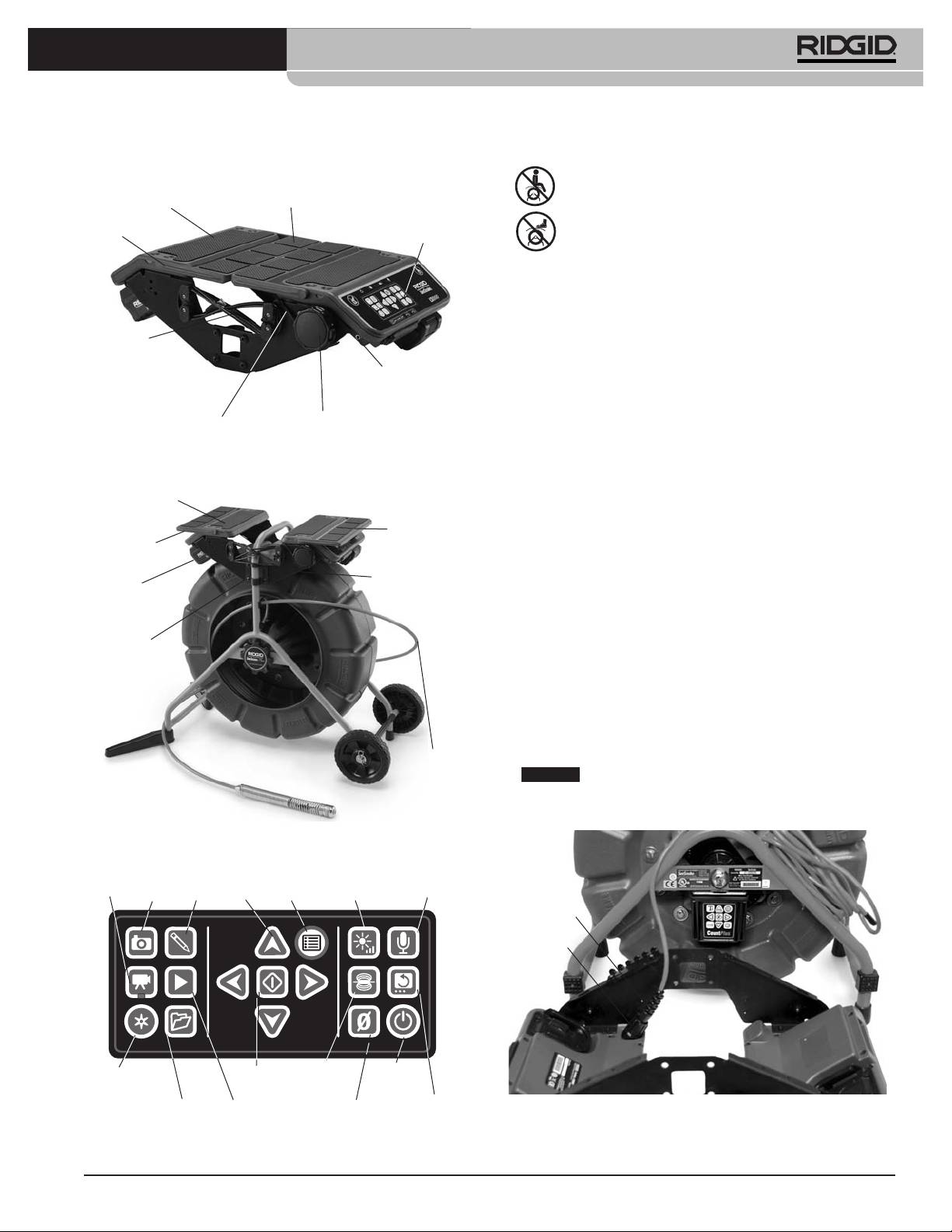
®
SeeSnake
LT1000
Componentes del LT1000
Íconos
No se siente sobre el LT1000.
Plataforma para la
computadora portátil
Ala desplegable
Placa lateral
No se suba al LT1000.
Teclado
Ensamblaje
Montaje del LT1000
El LT1000 se monta fácilmente sobre cualquier rollo
Cable USB
SeeSnake ya sea Standard o Mini. Su ensamblaje exige tan
sólo un desatornillador de punta cruciforme o Phillips y
Terminal de
7
una llave de cubo de
/
16
pulgada / 11 mm. Eso sí, la se-
enganche para el
transmisor
cuencia de su montaje sobre un rollo Mini, es diferente al
orden en que se va montando sobre un modelo Standard.
Cabrestante
Cordón de retención
para la computadora
Fíjese en que, en el caso de los rollos SeeSnake Stand-
ard, las partes curvas de los soportes de montaje deben
Figura 1 – Alas de la plataforma plegadas al centro
orientarse hacia fuera del LT1000. Mientras que, para el
Plataforma para
bastidor más angosto de los rollos Mini, las partes cur-
Alas de la plataforma extendidas
montar la
vas de los soportes de montaje apuntan hacia dentro.
computadora
Ala de la
plataforma
Ala de la
Montaje del LT1000 sobre un rollo
plataforma
SeeSnake Mini
Placa lateral
Pila de
1. Quite los dos soportes de montaje de los lados del LT1000.
18V
2. Antes de montar el LT1000 al bastidor del rollo Mini,
lleve el cable del sistema SeeSnake hasta el conec-
Soportes
tor del sistema SeeSnake. El cable del sistema
de montaje
SeeSnake tiene un reborde-guía moldeado en la
parte superior del enchufe del cable. Mientras
mantiene alineados el reborde-guía con la clavija-guía
en la parte superior del conector, introduzca el cable
del sistema en el conector y gire el manguito de fi-
jación hacia la derecha para apretarlo en posición.
Cable del
Sistema
AVISO
Al conectar o desconectar el cable del sistema
SeeSnake
SeeSnake, gire únicamente el manguito de fijación. Para
evitar daños, no doble ni tuerza el conector ni el cable.
Figura 2 – Componentes del LT1000
Tecla
Tecla
Tecla
de foto
Teclas
Tecla
Tecla para
de
de
etique-
de
de
Tecla de
silenciar el
video
foto
tada
flecha
Menú
luminosidad
micrófono
Reborde-guía
Manguito
de fijación
Tecla de
Tecla de
Tecla de
Tecla de
registro
Seleccionar
Sonda
encendido
automático
Tecla para
Tecla de
Tecla para
Tecla de
administrar
Reproducir
enderezar
Figura 4 – Conexión del cable del sistema SeeSnake
puesta a cero
Trabajos
la imagen
antes de montar el LT1000
Figura 3 – Teclado del LT1000
43
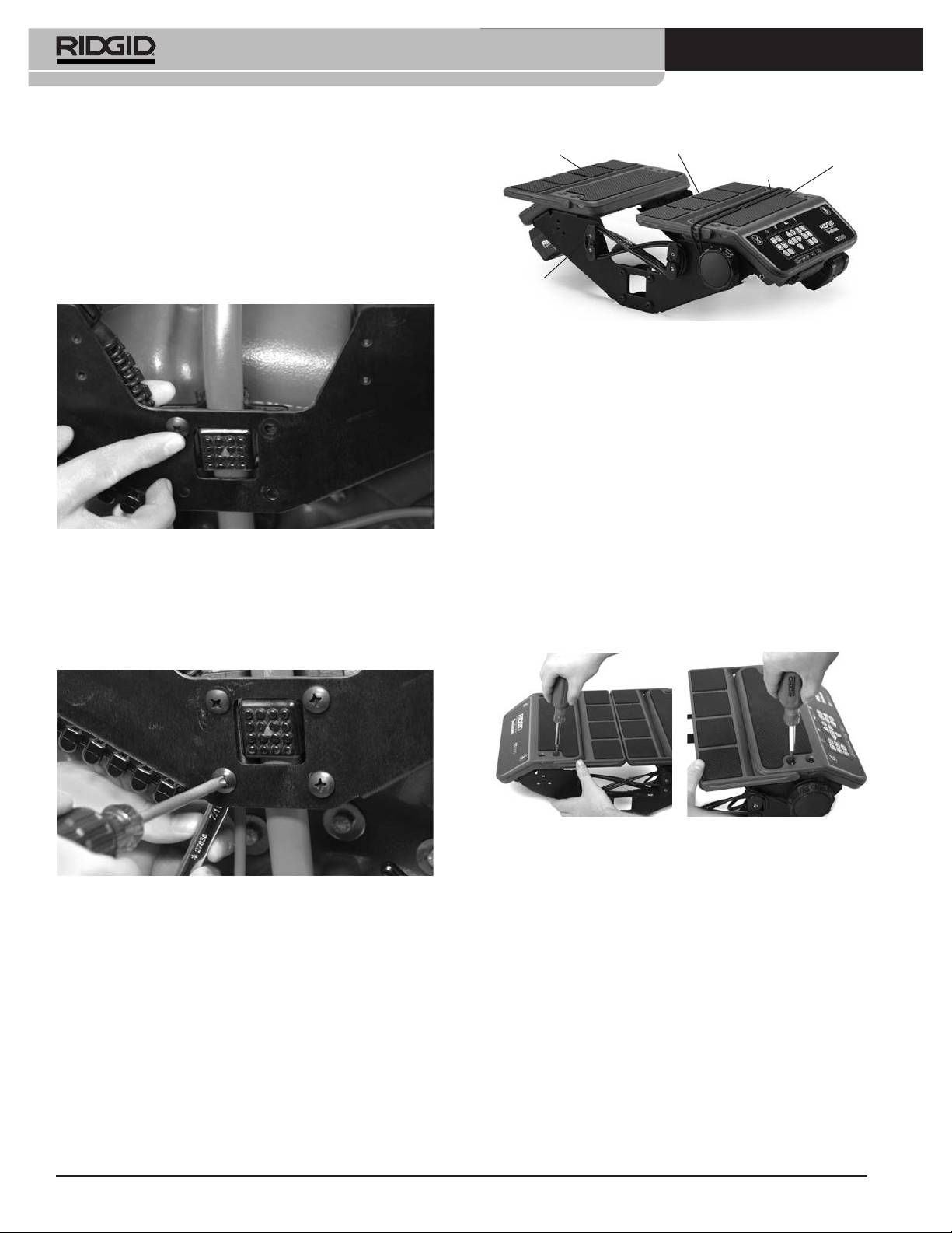
®
SeeSnake
LT1000
3. El rollo SeeSnake Mini exige que las partes curvas de
Plataforma
Alas
Cordón de
Plataforma
izquierda
retención para la
derecha
los soportes de montaje miren hacia dentro. Coloque
computadora
el LT1000 con la abertura en la placa lateral a caballo
sobre el “pie” en el armazón del rollo SeeSnake y
sosténgalo en posición mientras comienza a atornillar
los tornillos para metales a un lado del LT1000.
Acueste el rollo SeeSnake de espaldas, si lo desea,
para facilitar la instalación del panel delantero.
Cable USB
Figura 7 – Modo en que se juntan las alas de la
plataforma
Montaje del LT1000 sobre un rollo
SeeSnake Standard
Para montar el LT1000 sobre un rollo SeeSnake Standard
se requiere quitarle a la armazón del LT1000 las dos
secciones de su plataforma para la computadora, y el por-
tacable USB de la derecha.
1. Con un desatornillador cruciforme, extraiga los dos
tornillos del portacable USB del lado derecho (donde
Figura 5 – Primer tornillo para metales
se sujeta el cable USB y entra en el armazón del
LT1000). Desenrolle el cable USB fuera del porta-
4. Con un lado levemente sujeto en posición, alinee el
cable.
otro lado y ahora enrosque, parcialmente, los cuatro
tornillos pertenecientes a este lado. Las cabezas de
2. Extraiga los cuatro tornillos de cada una de las mi-
los tornillos deben entrar por la cara exterior del
tades de la plataforma.
LT1000 y las tuercas quedar en la cara interior.
Figura 8 – Extracción de los tornillos de las dos mitades
de la plataforma (SeeSnake Standard)
3. Levante y quite las dos mitades de la plataforma y
Figura 6 – Los tornillos para metales se aprietan
sitúelas cerca del rollo SeeSnake. Tenga cuidado de
5. Alinee el LT1000 para que quede derecho y nivelado
no perder los tornillos.
y apriete a mano los cuatro tornillos para metal en
4. Las dos placas laterales ahora estarán libres de las
cada lado. Con las alas de la plataforma cerradas,
mitades de la plataforma y podrán instalarse indivi-
debe quedar una separación de una pulgada / 2,5 cm
dualmente.
entre el rollo de cable y las alas. Apriete los ocho
tornillos con un desatornillador cruciforme.
6. Gire la perilla del cabrestante hacia la derecha para
soltar el cordón de retención para la computadora y
desenganche este cordón de los ganchos en el lado
de enfrente.
7. Traiga las dos alas de la plataforma hacia el centro,
juntándolas.
44
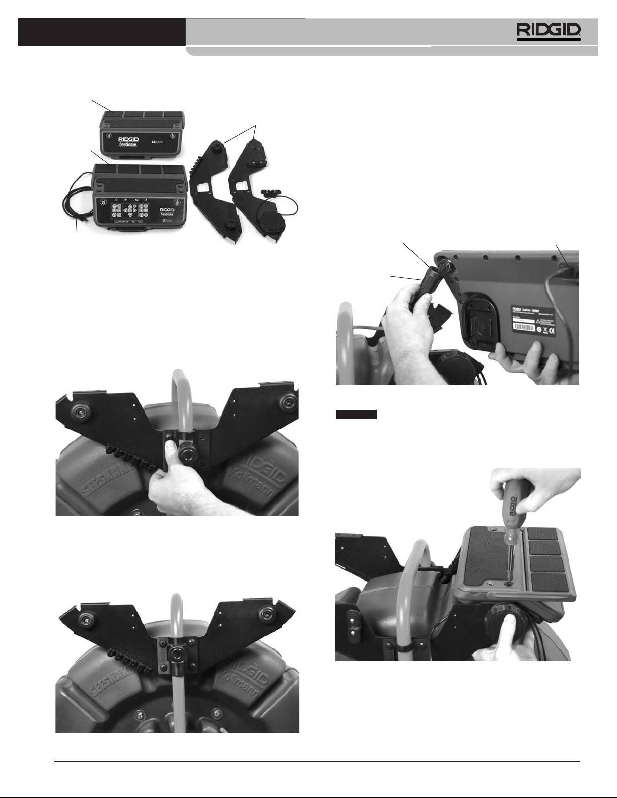
®
SeeSnake
LT1000
Mitad
8. Repita este mismo procedimiento con la otra placa la-
izquierda
teral y soporte al otro costado del rollo SeeSnake.
de la
Placas
plataforma
laterales
9. Pase el cable del sistema SeeSnake que sale del rollo
Mitad
por entre las placas laterales y conéctelo al conector
derecha
de la
SeeSnake ubicado debajo de la mitad derecha de la
plataforma
plataforma. El cable tiene sobre su enchufe macho
un manguito de fijación estriado. Alinee el manguito con
la clavija-guía en el conector, introduzca el cable del sis-
tema en el conector del sistema firmemente y gire el
manguito de fijación hacia la derecha para apretarlo en
posición.
Cable USB
Manguito de
Conector USB
Figura 9 – Partes del LT1000
fijación
5. Pase la placa lateral más cercana al operario por
Reborde-guía
detrás de la manija superior del rollo SeeSnake
moldeado
Standard. Tenga cuidado de no rayar el bastidor del
rollo.
6. Coloque el soporte de montaje sobre el tambor ex-
terior del rollo SeeSnake y alinee la placa lateral de
forma que sus agujeros coincidan con aquellos en el
soporte de montaje.
Figura 12 – Conexión del cable del sistema SeeSnake
AVISO
Cuando enchufe o desenchufe el cable del
sistema SeeSnake del conector correspondiente en el
LT1000, sólo gire su manguito de fijación. Para evitar que
se dañen, no tuerza el cable ni el conector mientras
los conecta.
Figura 10 – Alineamiento de uno de los soportes de mon-
taje con la placa lateral delantera
7. Introduzca los cuatro tornillos a través del soporte de
montaje y de la placa lateral para engranar con las
tuercas traseras. Apriételas a mano.
Figura 13 – Montaje de la plataforma derecha
10. Monte la mitad derecha de la plataforma (la con
teclado) alineándole sus agujeros en las alas de las
placas laterales y atorníllela a mano con sus cuatro
tornillos. Ajuste la plataforma para que quede nive-
lada.
Figura 11 – Placa lateral más cercana ya instalada
45
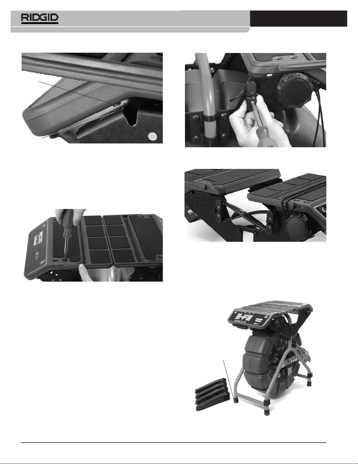
®
SeeSnake
LT1000
Borne
Agujero
Figura 14 – Bornes y agujeros para el alineamiento
Figura 16 – Montaje del portacable (debajo de él queda
A cada lado de la plataforma encontrará un pequeño
apresado el cable USB)
borne. Ambos deben asentarse en los agujeros corres-
pondientes.
11. Tome la mitad izquierda de la plataforma (sin teclado)
y asiéntela sobre los cuatro orificios, sobre las alas de
las placas laterales, introduzca los cuatro tornillos y
apriételos a mano.
Figura 17 – Portacable y cable USB
Instalación de los estabilizadores
Se proveen estabilizadores con el LT1000 los que le dan
mayor estabilidad a todo el equipo. Cada estabilizador
tiene una placa de resorte en su interior para fijarlo en
Figura 15 – Montaje de la plataforma izquierda
posición.
12. Ajuste ambas mitades de la plataforma y las placas
laterales para que ambas queden alineadas y nive-
ladas. Ahora apriete por completo todos los tornillos,
los de los soportes para el montaje y los de las dos
mitades de la plataforma.
13. Vuelva a colocar el portacable derecho y fíjelo en su
lugar (Figura 16) con dos tornillos. Fíjese en que el
cable USB queda apresado bajo del poste del por-
tacable cuando asoma del LT1000.
Pie de goma
Figura 18 – Estabilizadores para el rollo SeeSnake Mini
46
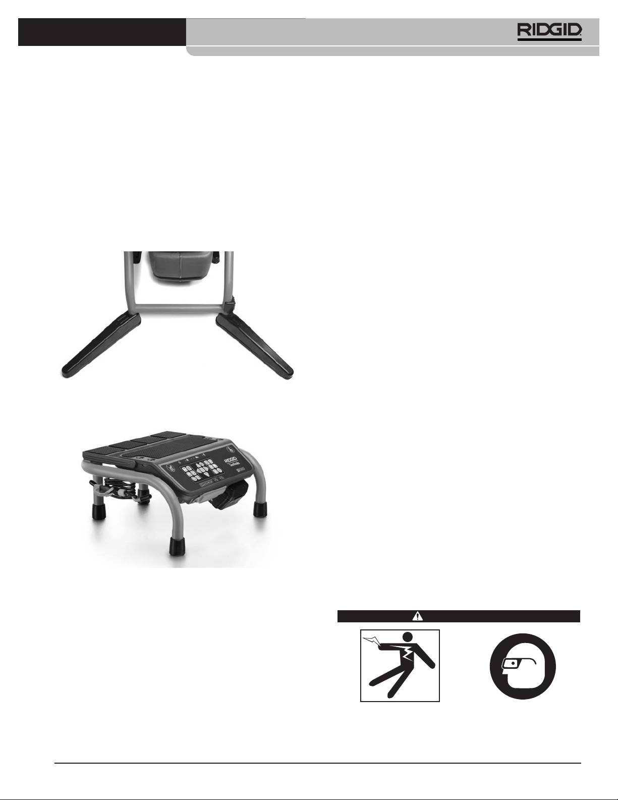
®
SeeSnake
LT1000
Instale los estabilizadores así:
crear, administrar y guardar imágenes, audio y video
desde el LT1000. Este software viene en el CD (disco
1. Extráigale el pie de goma a una de las cuatro patas
compacto) incluido con el LT1000. Para cargar el software
del armazón del rollo.
desde el CD en su computadora:
2. Coloque un estabilizador en esa pata del armazón,
Antes de conectar su computadora portátil al equipo
con la parte que no es hueca hacia arriba.
LT1000, usted debe haberle instalado previamente el
3. Vuelva a colocar el pie de goma y empújelo hasta
software SeeSnake HQ y sus controladores.
que tope.
1. Introduzca el CD en la disquetera para CDs en su
4. Haga lo mismo con las otras tres patas. Al armazón
computadora.
de los rollos Standard, más grandes, se le colocan
2. Su computadora portátil debería auto-detectar el CD
sólo dos estabilizadores, en las patas que no tienen
e iniciar la instalación. Podría solicitar una contraseña
ruedas.
administrativa (admin password) antes de proceder a
instalar el software HQ.
3. Terminada la instalación, expulse el CD y guárdelo en
un lugar seguro.
¡NOTA! El software se actualizará automáticamente
toda vez que su computadora portátil se en-
cuentre conectada a Internet. Cuando su com-
putadora detecte una actualización, preguntará
si usted desea instalarla. Si usted acepta, la ac-
tualización se cargará automáticamente. Es
posible averiguar en línea cuál es la versión
Figura 19 – Estabilizadores instalados
más reciente de este software ingresando a
través de un navegador de internet a
LT1000 Mini
http://www.hq.ridgid.com/product-hq.php .
4. O bien, el software más reciente puede instalarse
descargándolo desde este mismo sitio en la web,
subrayado más arriba, siguiendo sus instrucciones.
5. Lea las instrucciones de uso del software HQ para
aprender a gestionar sus cortos de video, fotos ins-
tantáneas, informes de trabajo, datos e informa-
ción sobre sus clientes y formatos, en
http://www.hq.ridgid.com/ . Aquí dispondrá de infor-
mación sobre cada aspecto de las capacidades de
HQ.
Figura 20 – LT1000 Mini
Inspección previa al
El LT1000 Mini es un armazón portátil sólido y resistente
funcionamiento
que sustenta a una unidad LT1000. Es liviano, fácil de
ADVERTENCIA
transportar y puede utilizarse con cualquier rollo SeeSnake
tan sólo conectándolos mediante el cable del sistema
SeeSnake. Es una alternativa económica si usted fre-
cuentemente trabaja con uno u otro rollo SeeSnake. El ar-
mazón LT1000 Mini viene de fábrica con la unidad LT1000
Mini ya instalada.
Preparación de la computadora portátil
Cada vez, antes de usar el SeeSnake LT1000, ins-
La computadora portátil que usted decida emplear en con-
pecciónelo y solucione cualquier problema que
junto con el LT1000, debe contener el software SeeSnake
pueda ocasionar graves lesiones debidas a descar-
gas eléctricas u otras causas, o provocar daños a la
HQ cargado en ella. El software SeeSnake HQ le permite
herramienta.
47
®
SeeSnake
LT1000
1. Asegure que el aparato se encuentra apagado, que
2. Échele una mirada a la zona donde trabajará. Hasta
sus cables están desconectados de la fuente de ali-
donde sea posible, determine dónde se encuentran
mentación o que sus pilas han sido extraídas. Inspec-
los accesos a la cañería o desagüe, su diámetro, lon-
cione todos los cordones, cables y conectores por si
gitud, y si contiene sustancias químicas de limpieza
están dañados o han sido modificados.
de desagües u otras que podrían resultar peligrosas.
Si la cañería contiene algún producto químico, es pri-
2. Quite el aceite, grasa o mugre del SeeSnake LT1000
mordial que usted sepa cómo debe protegerse de él.
para facilitar su revisión e impedir que sus mangos y
Para mayor información, contacte al fabricante del
controles resbalen de sus manos durante el uso o
producto.
transporte.
3. Establezca cuál es el equipo correcto que debe utilizar
3. Revise el LT1000 para asegurar que no le faltan
para el trabajo que realizará. El SeeSnake LT1000
piezas, que no tiene partes quebradas, desgastadas,
sirve para ver las inspecciones que lleva a cabo una
desalineadas o agarrotadas, o por si existe cualquiera
cámara dentro de una tubería. El catálogo Ridge
otra condición que pueda afectar su funcionamiento
Tool en línea en los sitios web www.RIDGID.com ó
normal y seguro. Cerciórese de que el equipo está en-
www.RIDGID.eu lista la totalidad de los equipos
samblado correctamente y de que el tambor gira li-
disponibles para todo tipo de inspecciones.
bremente. Revise que los soportes para el montaje
estén bien apretados.
4. Asegure que se ha revisado correctamente la totali-
dad del equipo.
4. Inspeccione cualquier otro aparato que se vaya a
utilizar, según sus propias instrucciones, y asegure
5. Observe los alrededores de la zona de trabajo y es-
que se encuentra utilizable.
tablezca si necesita poner barricadas o barreras
para impedir el ingreso a la zona de personas ajenas
5. Si detecta cualquier problema, no use la unidad
al trabajo. Los transeúntes distraen al operario. Si se
hasta que no haya sido reparada.
trabajará en un área de tráfico vehicular, circunde la
zona de trabajo con conos u otros dispositivos de
alerta.
Preparación del equipo y de la
zona de trabajo
6. Si es necesario, quite el artefacto sanitario (inodoro,
lavabo, etc.) para lograr acceso al desagüe.
ADVERTENCIA
Instalación del LT1000
Sitúe el rollo SeeSnake donde sea conveniente antes de
montar la computadora sobre el LT1000. Se alcanza la
manija superior del rollo SeeSnake desplegando ambas
alas de la plataforma hacia los lados del LT1000. El
cordón de retención puede pasar por debajo de la
plataforma y enrollarse en su portacable durante el trans-
Prepare el LT1000 y la zona de trabajo de acuerdo
a los siguientes procedimientos con el fin de pre-
porte.
venir lesiones por descargas eléctricas, incendios
Ponga el rollo SeeSnake y el LT1000 en un lugar donde
u otras causas, y daños al LT1000.
cómodamente pueda alcanzarlos y observar la pantalla
1. Revise que la zona de trabajo:
mientras usted dirige el cable de empuje -con la cámara
• esté bien iluminada,
en su punta- durante una inspección. Asegure que la
• no tenga líquidos, vapores o polvos inflamables
zona esté seca y que el LT1000 y los otros equipos no se
que puedan provocar un incendio. Si estos com-
mojarán mientras funcionan. El LT1000 no es a prueba de
bustibles están presentes, no trabaje en la zona
agua y si queda expuesto al agua podría ocasionar
hasta que hayan sido retirados. El LT1000 no está
descargas eléctricas o dañarse.
hecho a prueba de explosión. Las conexiones
eléctricas pueden despedir chispas.
Montaje de la computadora portátil
• tenga un lugar nivelado, estable y seco para situar
1. Afloje el cordón de retención girando el cabestrante
al operario. No use el aparato parado sobre agua.
hacia la derecha.
• tenga un sendero despejado hacia el tomaco-
2. Siente la computadora portátil en medio de la
rriente (si se necesita), donde no podrá dañarse el
plataforma para la computadora con su teclado orien-
cordón eléctrico.
tado hacia el teclado del LT1000.
48
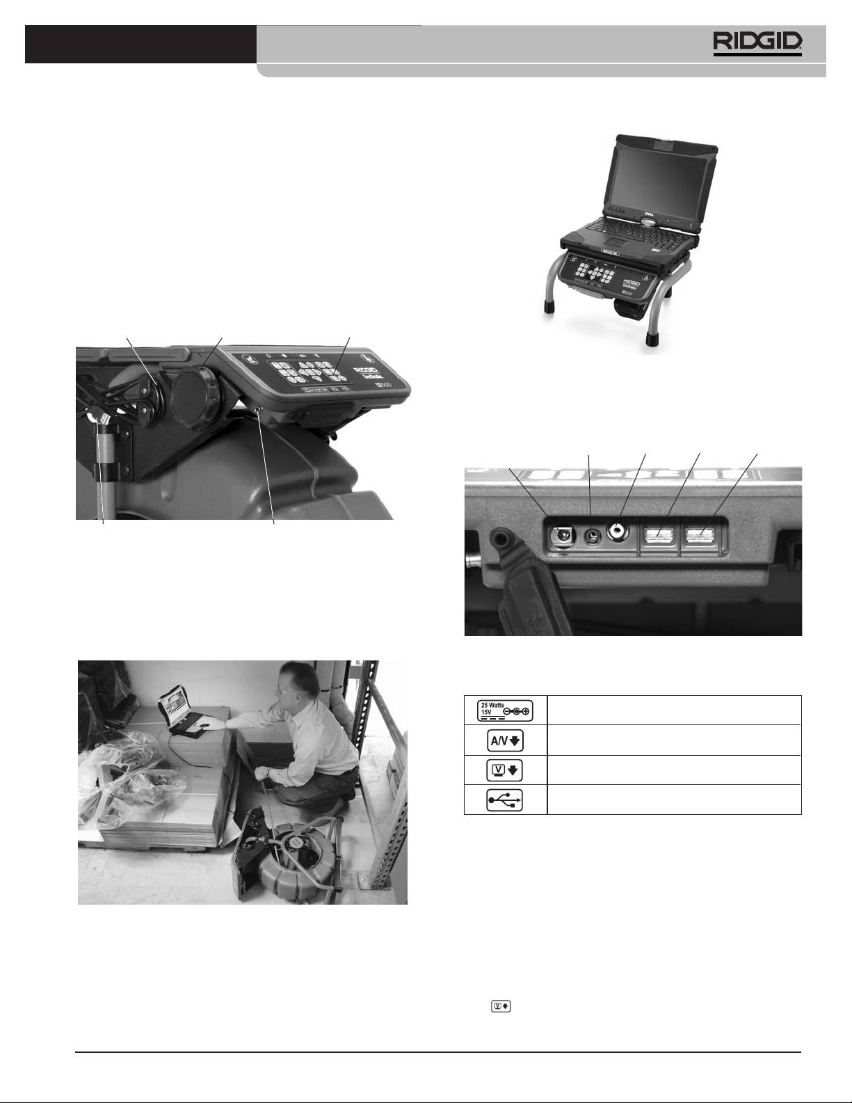
®
SeeSnake
LT1000
3. Pase el cordón de retención elástico por sobre la
computadora y engánchelo en los ganchos para el
cordón sin que interfiera con el funcionamiento de la
computadora.
4. Gire el cabestrante hacia la izquierda para tensar el
cordón de retención.
5. Lleve el cable USB del LT1000 hasta el puerto USB
de la computadora y enchúfelo en este puerto. Enrolle
el exceso de cable en el portacable USB (vea la
Figura 7).
Cordón de
Perilla del
retención
cabestrante
Teclado del LT1000
Figura 23 – LT1000 Mini con la computadora portátil
Conexión del LT1000
Enchufe hembra
para la
Puerto
Puerto
alimentación
Video OutA/V Out
USB
USB
externa
Cable USB
Terminal de enganche para el transmisor
Figura 21 – Teclado, cabestrante y cable USB
En lugares de trabajo constreñidos o inclinados, como un
tejado, tal vez usted prefiera acostar el rollo SeeSnake. Si
es así, desenrolle el cable USB –el que conecta a la
computadora con el rollo- y coloque la computadora
portátil sobre una superficie estable.
Figura 24 – Conexiones del LT1000
Íconos de conexión
Enchufe hembra para la alimentación externa
Enchufe hembra A/V out (DVDR externo, etc.)
Enchufe hembra Video Out (monitor externo)
Puerto USB (dispositivos portátiles de
almacenamiento de memoria, etc.)
Puede utilizarse un puerto USB para conectar a la com-
putadora un teclado portátil.
El enchufe hembra A/V Out funciona aunque no se esté
utilizando el software HQ.
Figura 22 – El rollo SeeSnake acostado y la computadora
Empleo de un monitor externo
puesta sobre una superficie estable
1. El LT1000 puede conectarse a un monitor externo
mediante un cable RCA desde el enchufe Video In en
el monitor. Conecte el otro extremo del cable en el
enchufe hembra VIDEO OUT del LT1000 marcado
en la parte posterior del LT1000.
49
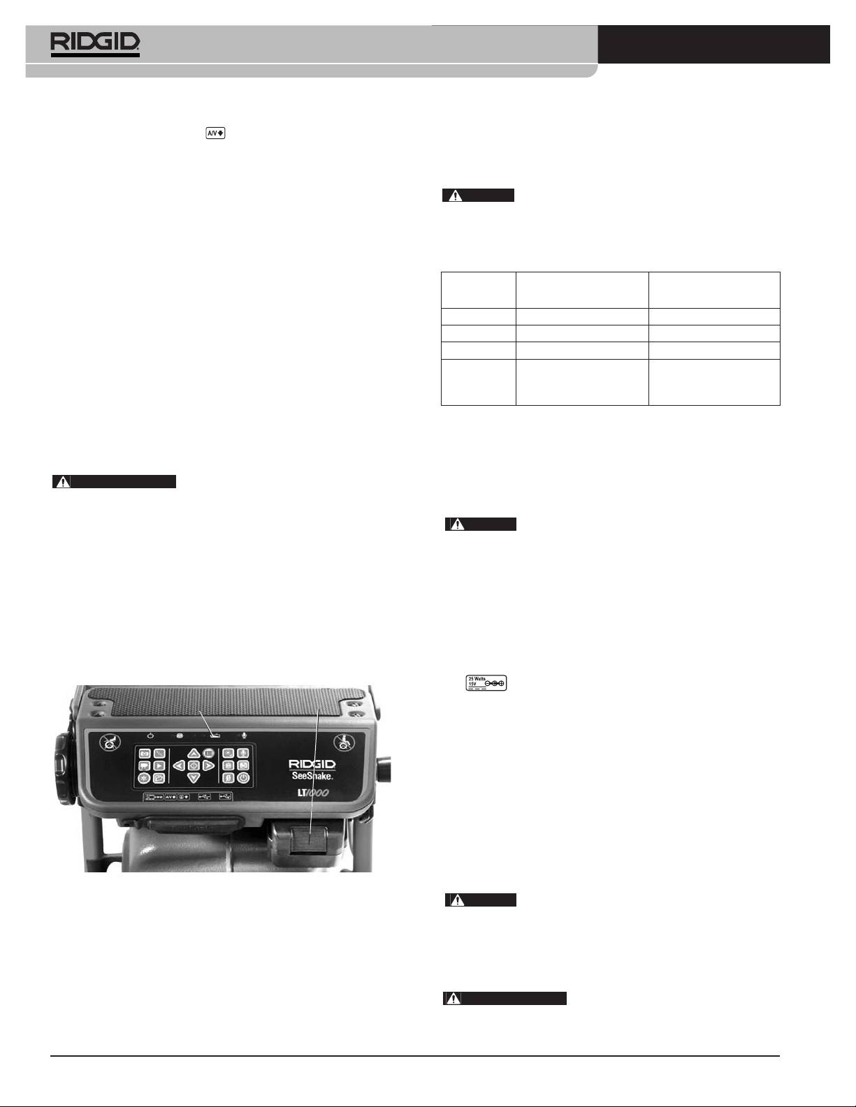
®
SeeSnake
LT1000
2. El puerto A/V OUT transmitirá video en vivo
LT1000, un diodo emisor de luz (DEL) muestra la carga
desde la cámara SeeSnake (conectada al LT1000) y
restante en la pila. (Vea la tabla siguiente que describe la
sonido en vivo desde el micrófono al DVDR o moni-
situación de carga de una pila).
tor. (Si se conecta a un monitor que cuenta con par-
AVISO
Antes de extraer o de reemplazar la pila,
lantes, podrían producirse chirridos, los que se
apague el LT1000. Si al aparato encendido se le quita la
pueden evitar poniendo el volumen del DVDR o
pila, podrían perderse filmaciones de la cámara.
monitor en el mínimo.)
La conexión USB desde el LT1000 sólo funciona cuando
DELs según situación de carga de la pila
está conectada a un dispositivo que está siendo contro-
CARGA EN SIN ALIMENTACIÓN ALIMENTACIÓN
lado por SeeSnake HQ.
LA PILA EXTERNA CONECTADA EXTERNA CONECTADA
Puesta en marcha del SeeSnake LT1000
LLENA Continuamente verde DELs apagados
MED Cont. verde y rojo DELs apagados
El SeeSnake LT1000 puede ser alimentado ya sea por
BAJA Cont. rojo, 4 pitidos DELs apagados
una pila recargable de li-ión de RIDGID o con su adap-
AGOTADA Cont. rojo por 5 segs, DELs apagados
tador de corriente alterna a continua (AC/DC, en in-
pitido por 5 segs.
glés) enchufado al suministro eléctrico. Es preferible
y apagamiento
hacerlo funcionar a pila para reducir el riesgo de descar-
gas eléctricas. Se advierte que el adaptador de co-
Funcionamiento eléctrico
rriente no es de uso exterior. No lo utilice a la in-
El LT1000 funciona con corriente eléctrica cuando se lo conecta
temperie.
a su adaptador de corriente (alterna a continua) con doble ais-
ADVERTENCIA
Emplee únicamente una pila o una
lamiento, incluido. El rol del adaptador es reducir el voltaje del
fuente de alimentación debidamente puesta a tierra para
suministro eléctrico que emana del tomacorriente de pared.
hacer funcionar tanto el LT1000 como cualquier com-
AVISO
putadora portátil que se use. Así se evitan los choques
El LT1000 no debe hacerse funcionar con su
eléctricos.
adaptador de corriente a la intemperie.
Para alimentar el sistema con el cable de alimentación, localice
Funcionamiento a pila
la toma de alimentación. El cable de alimentación tiene dos sec-
Con las manos secas, introduzca una pila cargada de
ciones, una de dos clavijas que se enchufa a una toma están-
18V en el compartimiento para la pila ubicado debajo del
dar de 110 - 120V (modelo EEUU) o toma estándar de 2
lado derecho del teclado del LT1000. También puede
patillas y 230V (modeloEU), y otra quese enchufaen una fuente
guardarse una pila de repuesto en un compartimiento de-
de alimentación en el otro extremo. La segunda sección del
bajo de la esquina diagonal del LT1000. (El hueco donde
cordón se extiende desde el adaptador hasta el conector hem-
se guarda esta pila no dispone de conexiones eléctricas.)
bra ubicado al extremo izquierdo del panel inferior de-
Carga de
la pila
Pila
Pila
lantero del LT1000 (Figura 24).
Con las manos secas, conecte las dos secciones del cordón
de alimentación e introduzca el extremo con el conector
macho en el conector hembra correspondiente en el LT1000.
Extienda el otro extremo del cordón por un sendero despejado
e introduzca su enchufe en el tomacorriente de pared. Si va
a utilizar un alargador, asegure que es del calibre adecuado.
Es necesario que un cordón de extensión de 25ʼ / 7,5 metros
2
tenga un calibre mínimo de 18 AWG / 0,8 mm
. Un cordón
alargador de más de 25ʼ / 7,5 metros debe tener un calibre
2
mínimo de 16 AWG / 1,5 mm
.
Figura 25 – Conexiones del LT1000
AVISO
Si la alimentación externa no es confiable y
Asegure que la pila encaje bien en su muelle. Revise el
produce picos transitorios de voltaje, el video LT1000
manual del operario del cargador de la pila si necesita
puede paralizarse. En este caso, simplemente apague el
mayor información.
LT1000 y vuelva a encenderlo. No se perderán los datos
de un trabajo, pero el conteo de la distancia en curso po-
La pila apta para hacer funcionar el LT1000 es de 2.2 / 2,2 amp-
dría volver a cero.
hr. Si totalmente cargada, dependiendo del tipo de servicio
ADVERTENCIA
Si la computadora portátil se
que preste (tiempo de grabación, etc.), alimentará al LT1000 por
conecta a la corriente alterna y su adaptador de la co-
2.5 / 2,5 a 3 horas. En la parte superior del teclado del
rriente alterna no cuenta con aislamiento, un retorno a
50
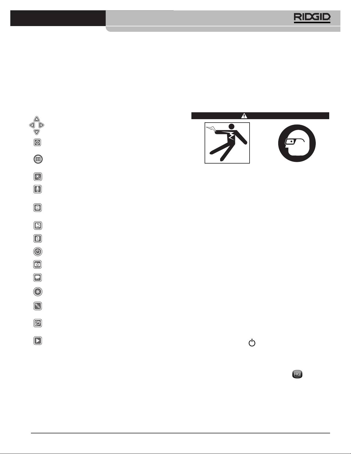
®
SeeSnake
LT1000
tierra podría dañar o averiar la computadora vía la
o unidad flash, o grabado en un DVD. El software HQ tam-
conexión USB a tierra.
bién hace posible organizar y almacenar fácilmente sus
trabajos o inspecciones para consultarlos en el futuro.
Cualquier computadora portátil que se utilice con el
LT1000 debe funcionar ya sea a pila o conectada a una
El software HQ se encuentra descrito en detalle en el sitio
alimentación externa provista de aislamiento.
http://www.hq.ridgid.com/ , en sus archivos de Ayuda.
Mandos del LT1000
Instrucciones de funcionamiento
Mandos en el teclado
WARNING
Teclas de flecha: se usan para recorrer opciones en los
menús y para regular variables, tales como el contraste.
Además, giran la imagen en pantalla.
Tecla de Seleccionar: se emplea para seleccionar entre las
3 opciones ofrecidas en el menú de escalas de medición
(Auto, Metros, Pies).
Tecla de Menú: hace aparecer el menú de opciones para la
visualización de las imágenes, como el color, luminosidad,
contraste y escalas de medición.
Use siempre protección para sus ojos, para que no
Tecla de Luminosidad: con ella se aumenta y disminuye
les entren mugre o partículas foráneas.
la luminosidad de los DELs de la cámara.
Al inspeccionar cañerías o desagües que puedan
Tecla para silenciar el micrófono: silencia el micrófono
contener sustancias químicas o bacterias, póngase
mientras se graba y lo activa si el inspector desea grabar sus
propios comentarios.
el equipo de protección personal adecuado, es
decir, guantes de goma o látex, gafas de seguridad,
Tecla de Sonda: activa la Sonda incorporada detrás del
máscara o respirador, para evitar quemaduras e
cabezal de la cámara con el fin de rastrear la trayectoria de
infecciones.
la cámara durante una inspección.
No haga funcionar este equipo si el operario o los
*Tecla para enderezar la imagen: gira y endereza la
imagen en pantalla.
aparatos estarán parados sobre agua. El riesgo de
sufrir descargas eléctricas es mayor cuando se
Tecla de puesta a cero: en rollos provistos de un contador
está en contacto con agua. Vista zapatos de suela
de distancias CountPlus, establece un punto cero temporal.
de goma: no sólo previenen las caídas, también las
descargas eléctricas.
Tecla de encendido: enciende y apaga el LT1000.
Siga fielmente las instrucciones de funcionamiento
*Tecla de foto: toma una foto o instantánea de la imagen
con el fin de reducir el riesgo de que descargas
que transmite la cámara.
eléctricas u otras causas lo lesionen.
Tecla de video: inicia y detiene la filmación de un video.
Inicio
*Tecla de registro automático: inicia la toma automática
de una serie de fotografías de la inspección en curso.
1. Asegure que el equipo de inspección se ha revisado
y ensamblado debidamente.
*Tecla de foto etiquetada: crea una nueva foto sobre la
cual el operario puede aplicar comentarios y etiquetas
electrónicas.
2. Asegure que la computadora portátil está bien mon-
tada y conectada, y que tiene el software HQ insta-
*Tecla para administrar trabajos: con ella se accede a un
menú de opciones para administrar e informar sobre
lado. Encienda la computadora.
inspecciones realizadas.
3. Introduzca el cabezal de la cámara por el aro-guía en
*Tecla de reproducción: Reproduce una grabación, si es
que se ha hecho una.
el rollo y encienda el LT1000.
* Algunos de los mandos del teclado no tendrán efecto alguno salvo
4. Al encenderse el LT1000, la computadora portátil
que el software HQ esté funcionando.
detectará el modelo del rollo SeeSnake presente y el
programa HQ se pondrá en marcha. Si no se inicia,
Software HQ
haga doble clic sobre el ícono HQ en su es-
El software HQ permite crear, gestionar y almacenar las
critorio para iniciarlo.
imágenes, audio y video desde el LT1000. Usted puede
utilizar HQ para rápida y automáticamente crear informes
5. Porque así se ha predeterminado, comenzará un
que podrá enviar por correo electrónico a un cliente. O
Trabajo nuevo. Se verá la imagen que transmite la
guardar este mismo informe en formato HTML y en-
cámara en este instante.
tregárselo al cliente en un dispositivo de almacenamiento
6. Si necesita consultar las instrucciones de uso del
software HQ, recurra a http://www.hq.ridgid.com/.
51
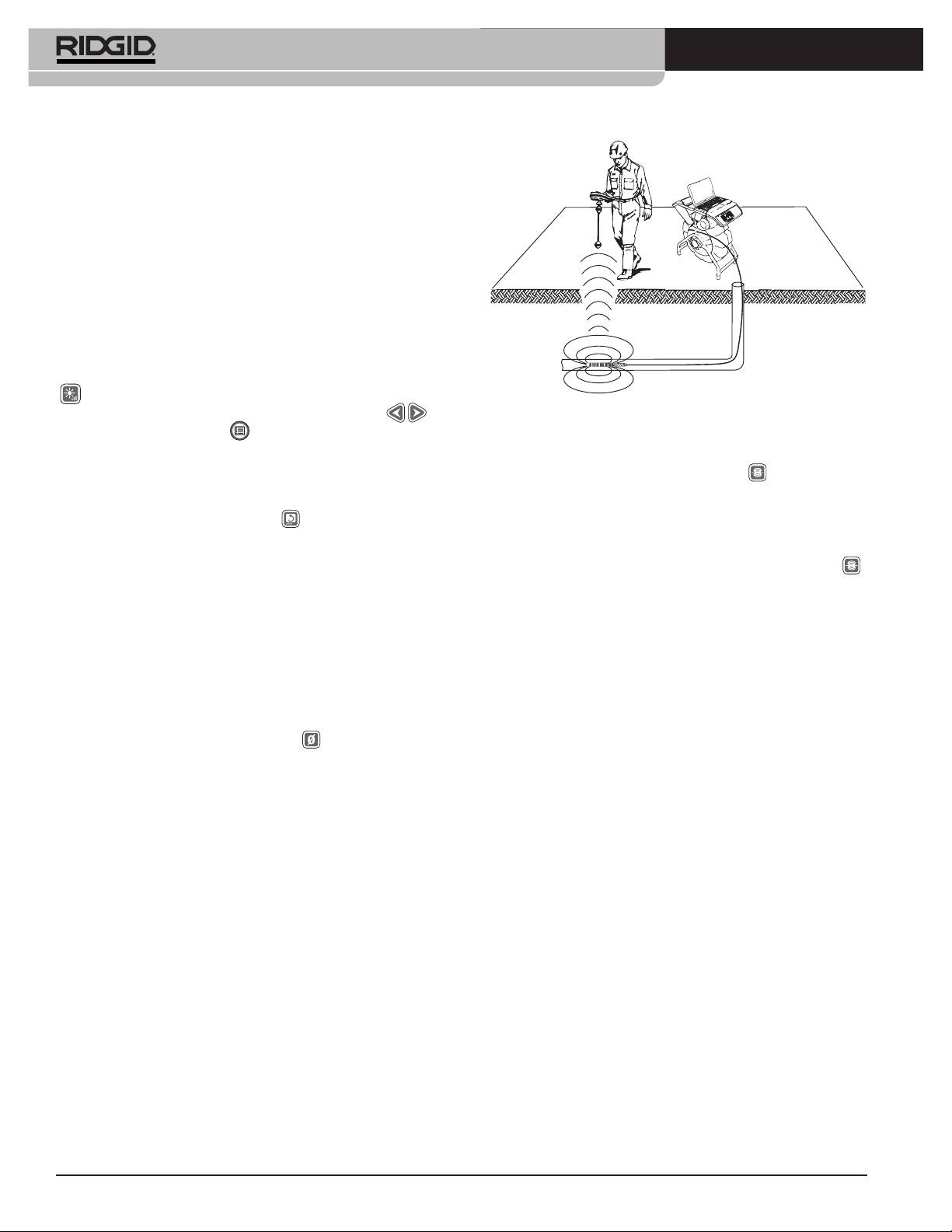
®
SeeSnake
LT1000
Inspección de una tubería
1. Si está apagado, encienda el LT1000.
2. Introduzca la cámara en el desagüe. Ponga el con-
tador en cero.
3. Proceda a inspeccionar la tubería como se describe
en el manual del rollo SeeSnake en uso.
Ajuste de la luminosidad
Es posible que usted requiera, mientras escudriña el in-
terior de una tubería, aumentar o disminuir la luminosidad
de los DELs de la cámara para mejorar la visualización.
Si es así, simplemente oprima la tecla de Luminosidad
y aumente o disminuya la luminosidad de la imagen
con las teclas de flechas derecha e izquierda .
Figura 26 – Localización de la Sonda
Oprima la tecla de Menú cuando haya terminado.
Para activar la Sonda SeeSnake al tiempo que se utiliza
Rotación de la imagen
el LT1000, oprima la tecla de Sonda . Aparecerá el
Es posible, asimismo, que la cámara se gire durante su
ícono de Sonda en la pantalla, siempre que la Sonda esté
recorrido y muestre una imagen invertida. Oprima la
encendida. Es posible que en la pantalla aparezcan al-
tecla para enderezar la imagen para verla, preferi-
gunas líneas de interferencia provenientes de la trans-
blemente vertical, en la pantalla. El software HQ también
misión de la Sonda. Éstas desaparecerán cuando usted
permite enderezar la imagen en cuestión de grados.
apague la Sonda al pulsar otra vez la tecla de Sonda .
Manejo del contador CountPlus
El método más viable para rastrear la Sonda consiste en in-
Si usted se encuentra utilizando un rollo SeeSnake
troducir el cable de empuje unos cinco a diez pies 1,5 a 3 met-
dotado de un contador de distancias CountPlus, la dis-
ros dentro de la cañería y utilizar el localizador para encontrar
tancia medida aparecerá en la pantalla de la computa-
la posición de la Sonda. A continuación, si desea, haga
dora. Si desea fijar un punto cero temporal de partida del
avanzar el cable otro trecho similar por la tubería y nueva-
conteo, para medir la distancia desde un punto dado
mente localice la Sonda, usando como punto de referencia la
dentro del desagüe (una unión, cambio de material de
posición localizada anteriormente. Encienda el localizador y
fabricación o inicio de una tubería distinta, por ejemplo),
póngalo en modalidad Sonda. Explore hacia el lugar donde
presione la tecla de puesta a cero . Ella iniciará un
probablemente se encuentra la Sonda hasta que el localizador
conteo temporal y los números de la medición apare-
la detecte. Una vez detectada la Sonda, siga las instruc-
cerán entre paréntesis cuadrados [0.0]. Para mayores
ciones en el manual del localizador en uso para concentrar su
detalles acerca del uso de la tecla de puesta a cero, con-
atención en ella y determinar con exactitud dónde se en-
sulte el manual del CountPlus.
cuentra. Para mayores detalles sobre localizaciones
asistidas por una Sonda, consulte el manual del operario
Los parámetros del CountPlus, tales como la fecha y
del modelo de localizador que utilizará.
hora, se fijan empleando la tecla de Menú en el propio
CountPlus, con la que se ingresa a su menú de He-
Rastreo del cable de empuje SeeSnake
rramientas. La escritura de texto con el CountPlus se
efectúa en el teclado del CountPlus, como se describe en
El LT1000 también le permite rastrear la trayectoria del
su manual.
conducto soterrado por donde se ha internado el cable de
empuje, con la ayuda de localizadores RIDGID como el
®
Localización de la cámara utilizando la
NaviTrack
II, el Scout™, el SR-20 o el SR-60. Para ras-
Sonda
trear el recorrido del cable SeeSnake, simplemente
conecte un transmisor con uno de sus conectores de-
La mayoría de los sistemas de inspección de tuberías
bidamente puesto a tierra mediante una estaca a tierra, y
SeeSnake cuentan con una Sonda incorporada, la cual
el otro conector enganchado al terminal de enganche
transmite una señal de 512Hz, susceptible de ser loca-
para el transmisor. Éste es una lengüeta metálica ubicada
lizada. Cuando esta Sonda está activada, puede ser de-
debajo del extremo izquierdo del teclado del LT1000
tectada por un localizador, como el SR-20, SR-60,
®
(Figura 27).
Scout™ ó NaviTrack
II de RIDGID, si puestos a 512Hz,
haciendo posible localizar -desde la superficie- la cá-
mara que se ha internado en una tubería soterrada.
52
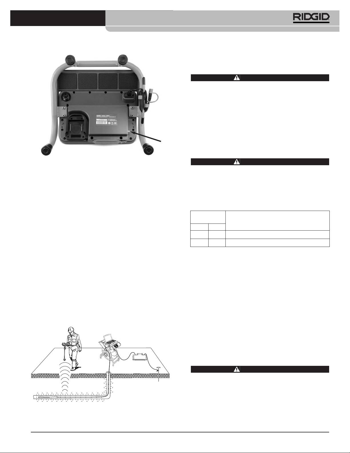
®
SeeSnake
LT1000
Instrucciones de mantenimiento
Limpieza
ADVERTENCIA
Antes de limpiar el LT1000 asegure que está sin la
pila y que todos los cables y cordones han sido
desconectados. Así se reduce el riesgo de que
ocurran descargas eléctricas.
No use líquidos ni limpiadores abrasivos sobre el LT1000.
Límpielo con un paño húmedo. No permita que al LT1000
le entren líquidos.
Accesorios
Figura 27 – Ubicación del terminal de enganche para el
ADVERTENCIA
transmisor
Los siguientes accesorios han sido diseñados para
funcionar con el LT1000. Otros accesorios aptos
para usarse con otros equipos podrían tornarse
Ponga el transmisor y el localizador a una misma fre-
peligrosos si se utilizan con el LT1000. Para evitar
cuencia 33kHz, por ejemplo- y emplee el localizador para
lesiones de gravedad, sólo use los accesorios he-
rastrear el conducto (Figura 28). La Sonda incorporada a
chos y recomendados para usarse con el LT1000,
la cámara, de 512Hz, puede permanecer encendida, y si
tales como los que se listan a continuación.
su localizador está dotado de la capacidad SimulTrace™
N° en el
de dos frecuencias, usted puede desde la superficie ir
catálogo
siguiendo el cable de empuje hasta la punta donde se en-
Descripción
EE.UU. CE
cuentra la cámara y luego detectar la Sonda.
32743 28218 Pila recargable de litio-ión 18V
Si no dispone de la característica SimulTrace™, emplee un
27958 32073 Cargador de pila
transmisor y un localizador para rastrear el cable de em-
puje. Cuando se debilite la señal, cambie la modalidad del
Transporte y almacenamiento
localizador a Sonda y regúlelo a la frecuencia de la Sonda
en el conducto, generalmente 512Hz. Recoja la señal
Extráigale la pila antes de embarcar el aparato. No lo
desde donde la señal comenzó a perderse y ahora con-
exponga a golpes fuertes durante su transporte. Si lo al-
centre toda su atención en la Sonda. Porque las fre-
macenará por largo tiempo, extraiga su pila. Guárdelo a
cuencias provenientes de un transmisor pueden causar
temperaturas entre 14°F a 158°F / -10°C a 70°C.
distorsiones en las imágenes en el monitor, se recomienda
Todos los aparatos eléctricos deben almacenarse en lu-
apagar la Sonda y el transmisor mientras se inspecciona
gares secos para evitar descargas eléctricas.
el interior de un conducto. Enciéndalos sólo cuando se
esté listo para efectuar una localización.
Protéjalo del calor excesivo. No guarde el equipo cerca de
artefactos que generan calor, tales como radiadores, re-
jillas de calefacción, estufas, cocinas eléctricas o amplifi-
cadores.
Servicio y reparaciones
ADVERTENCIA
El LT1000 puede tornarse inseguro de operar si se
le repara o mantiene incorrectamente.
El servicio y reparación del SeeSnake LT1000 deben
confiarse únicamente a un Servicentro Autorizado de
Figura 28 – El operario rastrea el cable de empuje
RIDGID.
53

®
SeeSnake
LT1000
Para obtener información acerca del Servicentro
Eliminación de las pilas
Autorizado RIDGID más cercano a su localidad o con-
En EE.UU. y Canadá: La presen-
sultar sobre el servicio o reparación de este equipo:
cia del sello de la RBRC™
• Contacte al distribuidor RIDGID en su localidad.
(Rechargeable Battery Recycling
• En internet visite el sitio www.RIDGID.com ó
Corporation) en los bloques de pilas
www.RIDGID.eu para averiguar dónde se encuentran
significa que RIDGID ha pagado por
los centros autorizados de Ridge Tool más cercanos.
anticipado el costo del reciclaje de
• Llame al Departamento de Servicio Técnico de Ridge
estas pilas de litio-ión.
Tool desde EE.UU. o Canadá al (800) 519-3456 o
®
RBRC™, RIDGID
y otros proveedores de pilas han
escriba a rtctechservices@emerson.com .
creado programas de recolección y reciclaje de pilas re-
Dirija sus mensajes electrónicos al Departamento de
cargables en los EE.UU. y Canadá. Las pilas corrientes y
Apoyo Técnico de HQ: HQSupport@seesnake.com
las recargables contienen materiales que no deben
echarse directamente a botaderos de basura como,
asimismo, elementos valiosos que pueden reciclarse.
Eliminación del equipo
Ayude a proteger el medio ambiente y a conservar re-
cursos naturales: lleve las pilas agotadas que usted tenga
Piezas y partes de este equipo están fabricadas de
en su poder a las tiendas de su localidad que participan en
materiales valiosos que pueden reciclarse. Averigüe
programas de reciclaje, a un servicentro autorizado de
cuáles empresas se especializan en reciclaje en su lo-
RIDGID o a uno de los centros urbanos de reciclaje en su
calidad. Deseche sus componentes cumpliendo con
municipio.
todas y cada una de las disposiciones vigentes en su ju-
risdicción. Para mayor información, llame a la agencia
RBRC™ es marca registrada de la Rechargeable Battery
local encargada de la eliminación de residuos sólidos.
Recycling Corporation.
En la Comunidad Europea: ¡No se de-
Países miembros de la CE: Las pilas o cápsulas de pilas
shaga de equipos eléctricos junto con la
usadas o defectuosas deben reciclarse según la directriz
basura doméstica! Según la directriz de la
2006/66/EC.
Comunidad Europea 2002/96/EC impartida
a sus países miembros sobre desechos
eléctricos y electrónicos, los equipos eléc-
tricos inutilizables deben ser recolectados en
forma separada de la basura municipal y eliminados sin
causar daños al medio ambiente.
54

®
SeeSnake
LT1000
Tabla 1 Detección de averías
PROBLEMA POSIBLE FALLA SOLUCIÓN
La pantalla no muestra
El rollo SeeSnake no recibe alimentación.
Revise que el equipo esté enchufado correcta-
imágenes desde la
mente o que la pila esté cargada.
cámara.
Oprima la tecla de encendido en el LT1000 para ver
si funciona.
Conexiones defectuosas.
Revise la conexión entre el LT1000 y el rollo
SeeSnake.
Revise los contactos y alvéolos de los conectores
en la conexión del sistema SeeSnake. Límpielos si
es necesario.
Pila con poca carga.
Cargue la pila o conecte el adaptador de corriente
a la corriente eléctrica y al equipo.
Aparecen advertencias
Pila de 18V en el LT1000 con poca carga.
Cargue la pila del LT1000. Conecte el equipo a la
sobre la pila.
corriente eléctrica (110 - 240V c.a.).
El video del LT1000 se
Suministro eléctrico de mala calidad o picos transi-
Encienda y apague el LT1000.
paraliza.
torios de voltaje.
No hay video.
Si su computadora no reconoce la conexión USB.
Reinicialice la computadora, encienda y apague
el LT1000 o cierre HQ y vuelva a iniciarlo para
ver si estas acciones corrigen el problema.
No encienda su computadora cuando el LT1000
El LT1000 debe apagarse; puede dejarse el cable
está funcionando.
USB conectado.
NOTA: El conector USB (ver la Figura 12) en el
LT1000 forma un sello a prueba de agua, por tanto
la conexión es firme. Su LT1000 fue probado y em-
balado con este cable firmemente asentado en el
conector. Si necesita desconectar y volver a conec-
tar este cable (por ejemplo, se averió el cable
USB), asegure que el nuevo enchufe macho quede
completamente asentado en el conector hembra.
De lo contrario, el software HQ no reconocerá al
LT1000. En el caso que no lo detecte, empuje el
conector hasta dentro. Es probable que tenga que
reiniciar el HQ para que detecte esta conexión.
55

®
SeeSnake
LT1000
56
