Panasonic EY7411: instruction
Class: Tools, power tools and power equipment
Type:
Manual for Panasonic EY7411
Operating Instructions
Bedienungsanleitung
Instructions d’utilisation
Istruzioni per l’uso
Cordless Drill & Driver
Gebruiksaanwijzing
Akku-Bohrschrauber
Manual de instrucciones
Perceuse et tournevis sur batterie
Brugsvejledning
Trapano e cacciavite senza lo
Draadloze boor en schroevendraaier
Driftsföreskrifter
Taladro y destornillador sin cable eléctrico
Bruksanvisning
Ledningsfri bor og skrutrækker
Käyttöohjeet
Laddningsbar borr/skruvdragare
Oppladbar drill og skrutrekker
Инструкция по эксплуатации
Ladattava porakone/ruuvinväännin
Iнструкцiя з експлуатації
Аккумуляторная дрель-шуруповерт
Аккумуляторний дриль-шуруповерт
Model No: EY7411
Before operating this unit, please read these instructions completely and save this manual for future use.
Vor Inbetriebnahme des Gerätes die Betriebsanleitung bitte gründlich durchlesen und diese Broschüre zum späteren Nachschlagen sorgfältig aufbewahren.
Lire entièrement les instructions suivantes avant de faire fonctionner l’appareil et conserver ce mode d’emploi à des fins de consultation ultérieure.
Prima di usare questa unità, leggere completamente queste istruzioni e conservare il manuale per usi futuri.
Lees deze gebruiksaanwijzing aandachtig door voor u het apparaat in gebruik neemt en bewaar de gebruiksaanwijzing voor eventuele naslag.
Antes de usar este aparato por primera vez, lea todas las instrucciones de este manual y guarde el manual para poderlo consultar en el futuro.
Gennemlæs denne betjeningsvejledning før brugen og gem den til fremtidig brug.
Läs igenom hela bruksanvisningen innan verktyget tas i bruk. Spara bruksanvisningen för senare användning.
Før enheten tas i bruk, vennligst les disse alle anvisningene og oppbevar deretter bruksanvisningen for senere bruk.
Lue ohjeet huolella ennen laitteen käyttöönottoa ja säilytä tämä käyttöohje tallessa tulevaa tarvetta varten.
Перед эксплуатацией данного устройства, пожалуйста, полностью прочтите данную инструкцию и сохраните данное руководство для использования в будущем.
Перед екплуатацiєю даного пристрою, будь ласка, повнiстю прочитайте дану iнструкцiю i збережiть даний посiбник для використання у майбутньому.
Index/Index/Index/Indice/Index/Indice/Indeks/Index/Indeks/Hakemisto
/
Индекс/Індекс
English: Page 6 Dansk: Side 73
Deutsch: Seite 18 Svenska: Sid 84
Français: Page 29 Norsk: Side 95
Italiano: Pagina 40 Suomi: Sivu 106
Nederlands: Bladzijde 51 Русский Страница 116
Español: Página 62 Українська Сторiнка 128
FUNCTIONAL DESCRIPTION
FUNKTIONSBESCHREIBUNG
DESCRIPTION DES FONCTIONS
DESCRIZIONE DELLE FUNZIONI
FUNCTIEBESCHRIJVING
DESCRIPCIÓN FUNCIONAL
FUNKTIONSBESKRIVELSE
FUNKTIONSBESKRIVNING
FUNKSJONSBESKRIVELSE
TOIMINTAKUVAUS
ФУНКЦИОНАЛЬНОЕ ОПИСАНИЕ
(
ФУНКЦIОНАЛЬНИЙ ОПИС
R
)
(
A
)
(
B
)
P
)
(
(
Q
)(
S
)
(
C
)
(
T
)
(
O
)
(
L
)
(
D
)
(
K
)
(
M
)
(
N
)
(
F
)
(
E
)
(
J
)
(
X
)
(
U
)
(
I
)
(
W
)
(
H
)
(
G
)
(
V
)
-
2
-

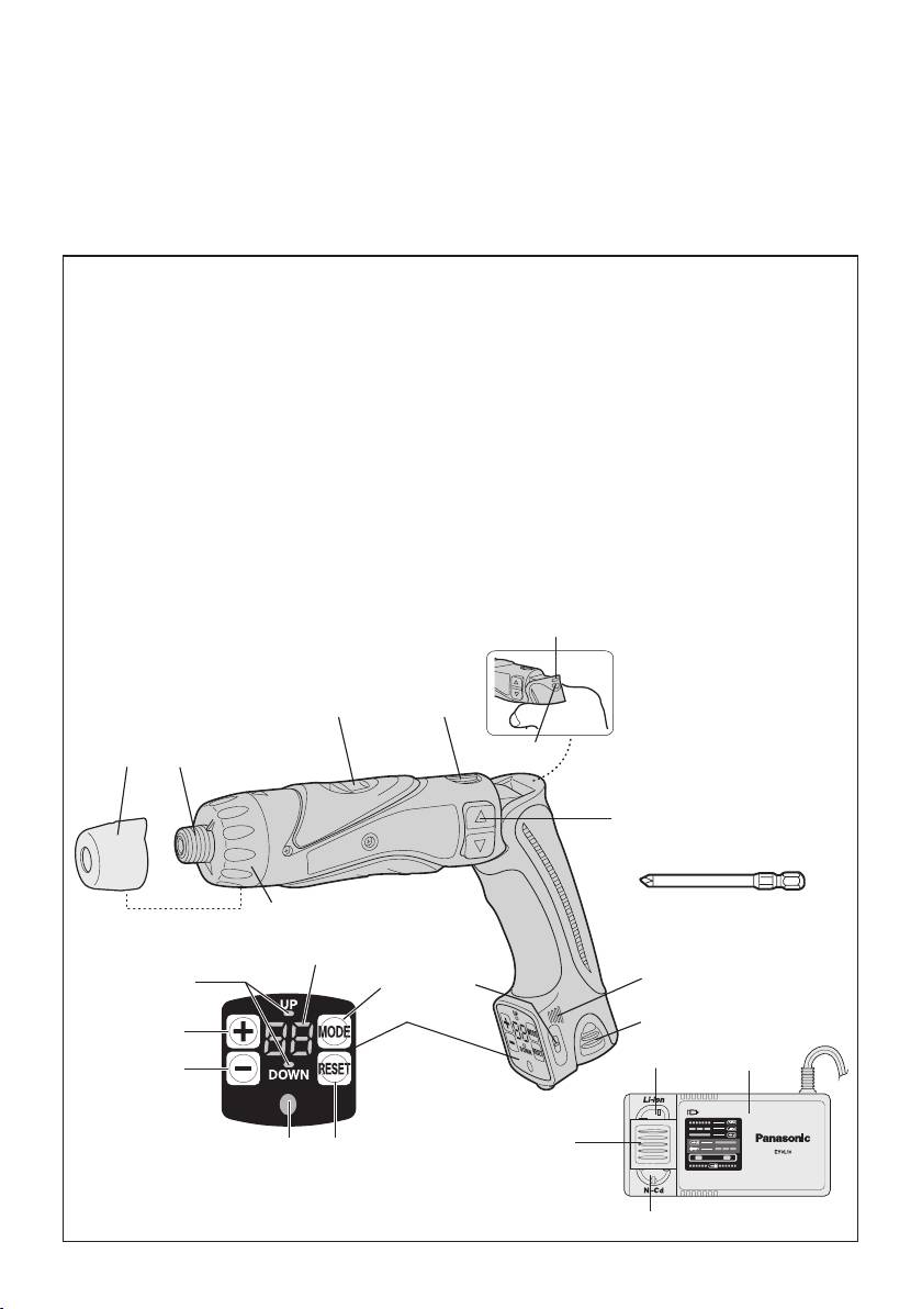
Speed selector switch
Main switch lock
Bereichsschalter
Hauptschaltersperre
Sélecteur de vitesse de rotation
Verrou de l’interrupteur principal
Selettore di velocità
Blocco interruttore principale
Snelheidskeuzeschakelaar
Hoofdschakelaarvergrendeling
Conmutador selector de velocidad
Bloqueo de interruptor principal
(
A
)
(
B
)
Hastighedsvælgeromskifter
Hoverafbryderlås
Varvtalsomkopplare
Strömbrytarspärr
Hastighetsvelger
Hovedbryterlås
Nopeusalueen valitsin
Pääkytkimen lukko
Селекторныйпереключательскорости
Блокировкаглавногопереключателя
Селекторнийперемикачшвидкості
Блокуванняголовногоперемикача
Forward/Reverse switch
Buzzer sound part
Vorwärts-/Rückwärtsschalter
Summertonteil
Sélecteur de marche avant/marche arrière
Pièce de l’alarme
Interruttore di avanzamento/inversione
Sezione suono del cicalino
Links/rechtsschakelaar
Zoemertoongedeelte
Conmutador de avance/marcha
Parte de sonido de zumbador
(
C
)
(
D
)
Knap til forlæns/baglæns retning
Summetonedel
Riktningsomkopplare
Summerljudsdel
Forover-/bakoverbryter
Summertonedel
Eteenpäin/taaksepäin kytkin
Summerin ääniosa
Переключательвперед/назад
Элементзвуковогосигнала
Перемикачвперед/назад
Елементзвуковогосигналу
Battery pack (EY9L10)
Control panel
Akku (EY9L10)
Bedienfeld
Batterie autonome (EY9L10)
Panneau de commande
Pacco batteria (EY9L10)
Pannello di controllo
Accu (EY9L10)
Bedieningspaneel
Batería (EY9L10)
Panel de controlp
(
E
)
(
F
)
Batteripakning (EY9L10)
Kontrolpanel
Batteri (EY9L10)
Kontrollpanel
Batteri-pakke (EY9L10)
Kontrollpanel
Akku (EY9L10)
Säätöpaneeli
Батарейныйблок
(EY9L10)
Панельуправления
Батарейнийблок
(EY9L10)
Панельуправління
Reset button
LED light
Rückstelltaste
LED-Leuchte
Bouton de remise à zéro
Lumière DEL
Tasto di azzeramento
Luce LED
Resettoets
LED-lampje
Botón de reposición
Luz indicadora
(
G
)
(
H
)
Nulstillingsknap
LED-lys
Återställningsknapp (RESET)
LED-ljus
Tilbakestillingsknapp
LED-lys
Palautuspainike
LED-valo
Кнопкасброса(RESET)
Светодиоднаяподсветка
Кнопкаскидання(RESET)
Світлодіоднепідсвічування
-
3
-

– (MINUS) button
+ (PLUS) button
Taste – (MINUS)
Taste + (PLUS)
Bouton – (MOINS)
Bouton + (PLUS)
Tasto – (MENO)
Tasto + (PIÙ)
– (MIN) toets
+ (PLUS) toets
Botón – (MENOS)
Botón + (MÁS)
(
I
)
(
J
)
- (MINUS) knap
+ (PLUS) knap
Minusknapp (–)
Plusknapp (+)
– (MINUS)-knapp
+ (PLUSS)-knapp
(MIINUS)-painike
(PLUS)-painike
Кнопка–(МИНУС)
Кнопка+(ПЛЮС)
Кнопка−(МІНУС)
Кнопка+(ПЛЮС)
Count system display lamp
Count display LED
Zählsystem-Anzeigelampe
Zählungsanzeige-LED
Voyantd’afchagedusystèmedecomptage
DELdel’afchageducompteur
Lampada del display del sistema di conteggio
LED del display di conteggio
Telsysteem-aanduidingslampje
Teldisplay-LED
Luz indicadora del sistema de cuenta
LED indicadora de cuenta
(
K
)
(
L
)
Tællesystemvisningslampe
Tællevisning-LED
Indikatorer för räkningsmetod (UP/DOWN)
LED-räkneverk
Displaylys for tellesystem
LED-lys for tellerdisplay
Laskujärjestelmän näyttölamppu
Laskunäytön LED
Индикатордисплеясистемыподсчета
Светодиодныйдисплейсистемыподсчета
Індикатордисплеясистемипідрахункуr
Світлодіоднийдисплейсистемипідрахунку
Mode Button
Hold switch
Modustaste
Halteschalter
Bouton de Mode
Sélecteur de pause
Tasto modalità
Interruttore di mantenimento funzione
Functietoets
Blokkeerschakelaar
Botón de modo
Conmutador HOLD
(
M
)
(N)
Funktionsknap
Hold-knap
Lägesväljare (MODE)
Inställningslås (HOLD)
Modus-knapp
Hold-bryter
Muotopainike
Pitokytkin
Кнопкапереключениярежимовработы(MODE)
Выключательблокировки
Кнопкаперемиканнярежимівроботи(MODE)
Вимикачблокування
Clutch handle
Clutch lock cover
Kupplungsring
Kupplungssperrenabdeckung
Poignée de l’embrayage
Couvercle du verrou de l’embrayage
Impugnatura frizione
Coperchio blocco frizione
Koppelingshandgreep
Afdekkap voor koppelingsvergrendeling
Mango de embrague
Cubierta de bloqueo de embrague
(O)
(P)
Koblingshåndtag
Dæksel til koblingslås
Kopplingshandtag
Kopplingsspärrkåpa
Clutchhåndtak
Clutchlåsedeksel
Kytkimen kahva
Kytkimen lukon kansi
Рукояткамуфты
Крышкаблокировкимуфты
Рукояткамуфти
Кришкаблокуваннямуфти
-
4
-

Hexagonal bit chuck
Battery low warning lamp
Sechskantbitfutter
Akkuladungs-Warnlampe
Mandrin de mèche hexagonal
Témoin d’avertissement de batterie basse
Mandrino esagonale per punte
Spia avvertenza batteria scarica
Zeskantboorkop
Waarschuwingslampje voor lage accuspanning
Portador de broca hexagonal
Luz de aviso de baja carga de batería
(Q)
(R)
Sekskantet borepatron
Advarselslampes batterieffekt lav
Chuck för sexkantsbits
Varningslampa för svagt batteri
Sekskantet borchuck
Varsellampe for at batteriet er for lavt
Kuusioterän kiinnityslaite
Alhaisen akkujännitteen varoituslamppu
Шестигранныйзажимнойпатрондлянасадок
Предупреждающаялампочканизкогозарядабатареи
Шестиграннийзатискнийпатрондлянасадок
Попереджувальналампочканизькогозарядубатареї
LED light ON/OFF button
#2 Phillips bit
LED-Leuchten-EIN/AUS-Taste
#2 Kreuzschlitzbit
Bouton Marche/Arrêt de la lumière DEL
Mèches Phillips #2
Tasto di accensione e spegnimento della luce LED
2 bit Philips
Aan/uit-toets (ON/OFF) voor LED-lampje
#2 Kruiskopbit
Botón ON/OFF de luz LED
Broca Philips No2
TÆND/SLUK-knap til LED-lys
(S)
(T)
Strömbrytare för LED-ljus
#2 Phillips-bit
PÅ/AV-knapp for LED-lys
Kryssmejselbits #2
LED-valon kytkin/katkaisupainike
#2 Phillips bit
Кнопкавключения/выключениясветодиодной
Philips-terä #2
подсветки
Крестообразнаянасадка№2
Кнопкаввімкнення/вимкненнясвітлодіодного
підсвічування
Хрестоподiбнанасадка№2
Battery charger (EY0L10)
Ni-Cd battery pack dock
Ladegerät (EY0L10)
Ni-Cd-Akkuladeschacht
Poste d’accueil de la batterie autonome Ni-Cd
Chargeur de batterie (EY0L10)
Spazio raccordo pacco batteria Ni-Cd
Caricabatterie (EY0L10)
Ni-Cd accuhouder
Acculader (EY0L10)
Enchufe de carga de batería Ni-Cd
Cargador de la batería (EY0L10)
Ni-Cd batteripakningsdok
(U)
(V)
Batterioplader (EY0L10)
Docka för NiCd-batteri
Batteriladdare (EY0L10)
Dokk for Ni-Cd-batteripakke
Batterilader (EY0L10)
Ni-Cd akun liitin
Углублениедляустановкиникель-кадмиевого
Akkulaturi (EY0L10)
батарейногоблока
Зарядноеустройство
(EY0L10)
Заглибленнядлявстановленнянікель-
Заряднийпристрiй
(EY0L10)
кадмієвогобатарейногоблоку
Li-ion battery pack dock
Battery dock cover
Li-Ion-Akkuladeschacht
Ladeschachtabdeckung
Poste d’accueil de la batterie autonome Li-ion
Couvercle du poste d’accueil de la batterie
Spazio raccordo pacco batteria Li-ion
Coperchio vano batteria
Li-ion accuhouder
Deksel van accuhouder
Enchufe de carga de batería Li-ión
Cubierta de enchufe de carga de batería
Li-ion batteripakningsdok
(W)
(X)
Batteridokdæksel
Docka för litiumjonbatteri
Batteridockningslucka
Dokk for Li-ion-batteripakke
Batteridokkdeksel
Li-ioniakun liitin
Akkuliittimen kansi
Углублениедляустановкилитий-ионного
батарейногоблока
Крышкауглублениядлябатареи
Заглибленнядлявстановленнялітій-іонного
Кришказаглибленнядлябатареї
батарейногоблоку
-
5
-
Read the Safety Instructions booklet and
WARNING:
the following before using.
• Do not use other than the Panasonic
battery packs that are designed for
I
. ADDITIONAL
use with this rechargeable tool.
•
Do not dispose of the battery pack in
SAFETY RULES
a fire, or expose it to excessive heat.
1) Wear ear protectors when using
•
Do not drive the likes of nails into the
the tool for extended periods.
battery pack, subject it to shocks, dis-
Prolonged exposure to high inten
-
mantle it, or attempt to modify it.
sity noise can cause hearing loss.
• Do not allow metal objects to touch
2) Be aware that this tool is always in
the battery pack terminals.
an operating condition, since it does
not have to be plugged into an elec-
•
Do not carry or store the battery pack
trical outlet.
in the same container as nails or
similar metal objects.
3) When drilling into walls, floors, etc.,
“live” electrical wires may be encoun-
•
Do not charge the battery pack in
tered. DO NOT TOUCH THE CHUCK
a high-temperature location, such
OR ANY FRONT METAL PARTS OF
as next to a fire or in direct sunlight.
THE TOOL! Hold the tool only by the
Otherwise, the battery may overheat,
plastic handle to prevent electric shock
catch fire, or explode.
in case you drill into a “live” wire.
•
Never use other than the dedicated
4) If the bit becomes jammed, immedi
-
charger to charge the battery pack.
ately turn the main switch off to pre-
Otherwise, the battery may leak,
vent an overload which can damage
overheat, or explode.
the battery pack or motor.
Use reverse motion to loosen jammed
bits.
II
. ASSEMBLY &
5) During charging, the charger may
become slightly warm. This is nor-
OPERATION
mal. Do not leave the battery in
the charger for more than 24 hours
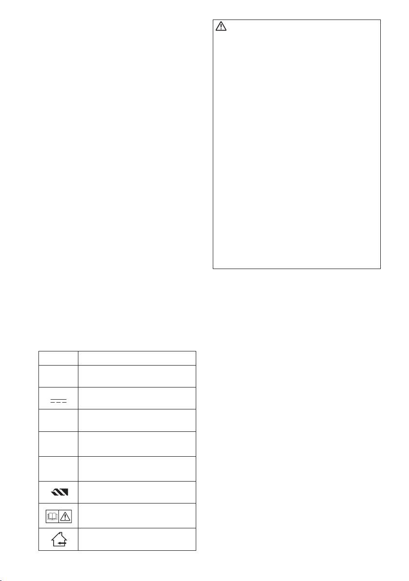
Hexagonal Bit Chuck
after charging is completed.
Attaching the bits
Symbol Meaning
NOTE:
When attaching or removing drill
V
Volts
bits, disconnect the battery pack
from the tool and switch the lock
button into the lock position.
Direct current
1. Hold the collar of the chuck and pull it
out from the driver.
n
0
No load speed
2. Insert the bit into the chuck. Release
-1
Revolutions or reciprocations
the collar.
… min
per minutes
3. The collar will return to its original
position when it is released.
Electrical capacity of battery
Ah
pack
4. Pull the bit to make sure it does not
come out.
Rotation only
5. To remove the bit, pull out the collar in
the same way.
Read the operating instructions
before use.
For indoor use only.
-
6
-
Bit
Hexagonal bit chuck
NOTE:
The chart is only a reference. The
torque settings may differ by materi-
als, types of screws, etc. Please test
it at your own conditions before use.
9.5 mm (3/8") - 13 mm (33/64") 6.35 mm (1/4")
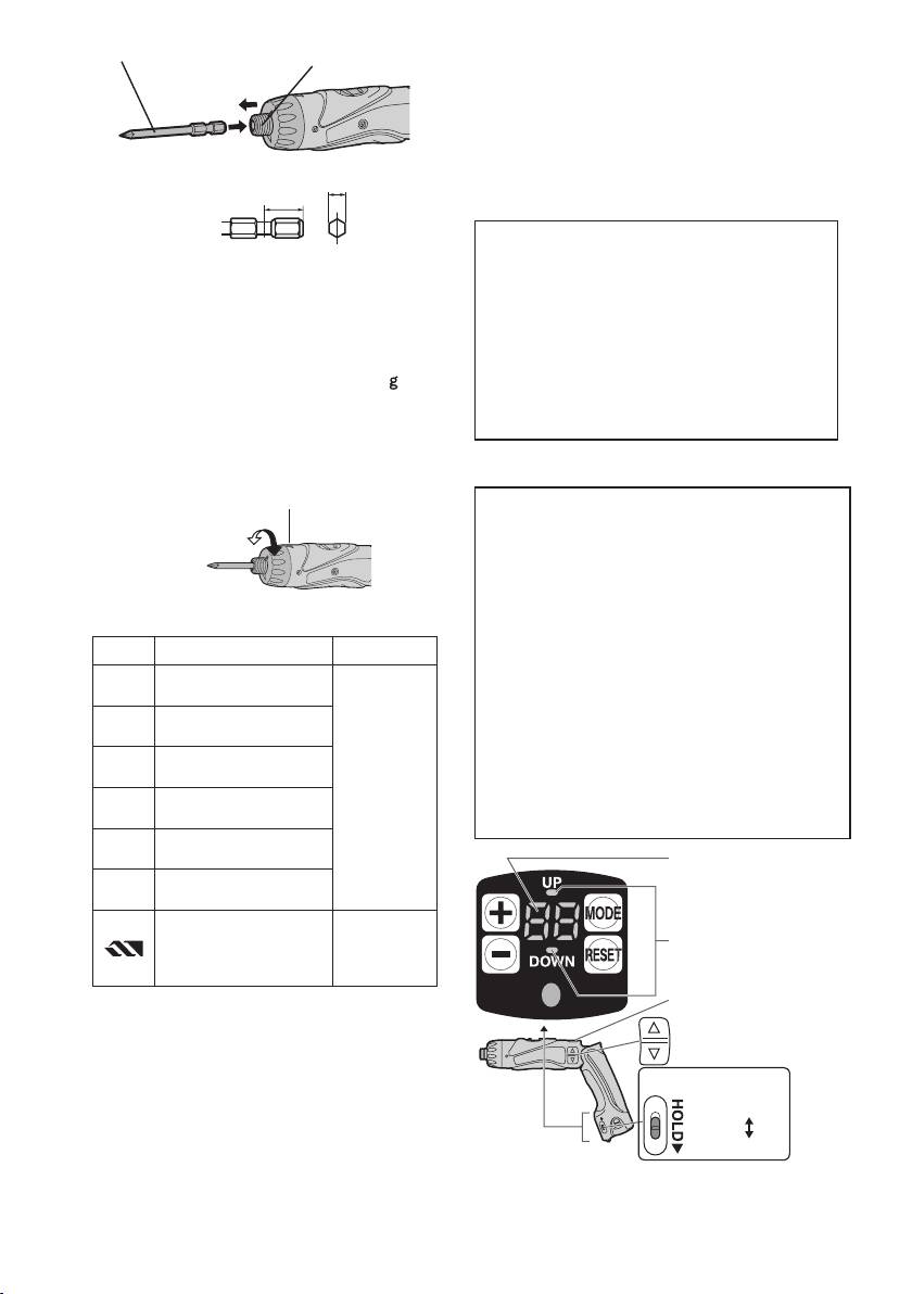
Control Panel
Manufacturer settings upon shipment
●
Count system: Count down system
Clutch Handle
●
Count setting value: 99
(Clutch Torque Setting)
●
Buzzer sound pitch: b1 (Low sound)
Adjust the torque to one of the 21 pos-
●
Double tightening counting preven-
sible settings to the job. There is an
tion count time: 0 (OFF)
interval of about 0.13 N·m (1.3 k f-cm
●
Hold switch: Released
or 1.1 in-lbs) between steps.
Please set the settings according to
CAUTION:
conditions of use.
Test the setting before actual opera-
tion.
Screw count function
Set the scale at this mark.
●Countsthe number of autostops.
(Counts the number of screws driven)
●Thecount methodcanbe selected
from “UP” or “DOWN”.
●Whenthesetnumberofscrewstobe
Reference for Adjusting Torque
driven is reached, a buzzer sounds
and the count value is reset.
Setting
Torque Use
●Thebuzzer sound canbe selected
Approx: 0.29 N
·
m
1
(3.0 k
g
f-cm or 2.6 in-lbs)
from 3 types of sound.
Approx: 0.82 N
·
m
●Doubletighteningcountingprevention
5
(8.4 kgf-cm or 7.3 in-lbs)
function
Approx: 1.35 N
·
m
Work (double tightening and screw
9
(13.8 kgf-cm or 12.0 in-lbs)
For driving
driving confirmation, etc.) that began
screws
Approx: 1.88 N
·
m
13
within the set time is not counted after
(19.2 kgf-cm or 16.6 in-lbs)
the driven screws are counted.
Approx: 2.41 N
·
m
17
(24.6 kgf-cm or 21.3 in-lbs)
Count display lamp
Approx: 2.94 N
·
m
21
(30.0 kgf-cm or 26.0 in-lbs)
For power-
Approx: 4.4 N
·
m
ful driving
Count system display
(45.0 kgf-cm or 39.0 in-lbs)
screws and
lamp
drilling
Lock button
● When using at high speeds, set the
clutch at 10 or below. (Operation
Switch
stops at the maximum torque of 1.5
N·m (15 kgf-cm) when the scale is
Hold switch
higher.)
Release
● The auto shut-off function may
become inoperable at high clutch
ON
settings when battery power drops.
Recharge the battery in that case.
-
7
-
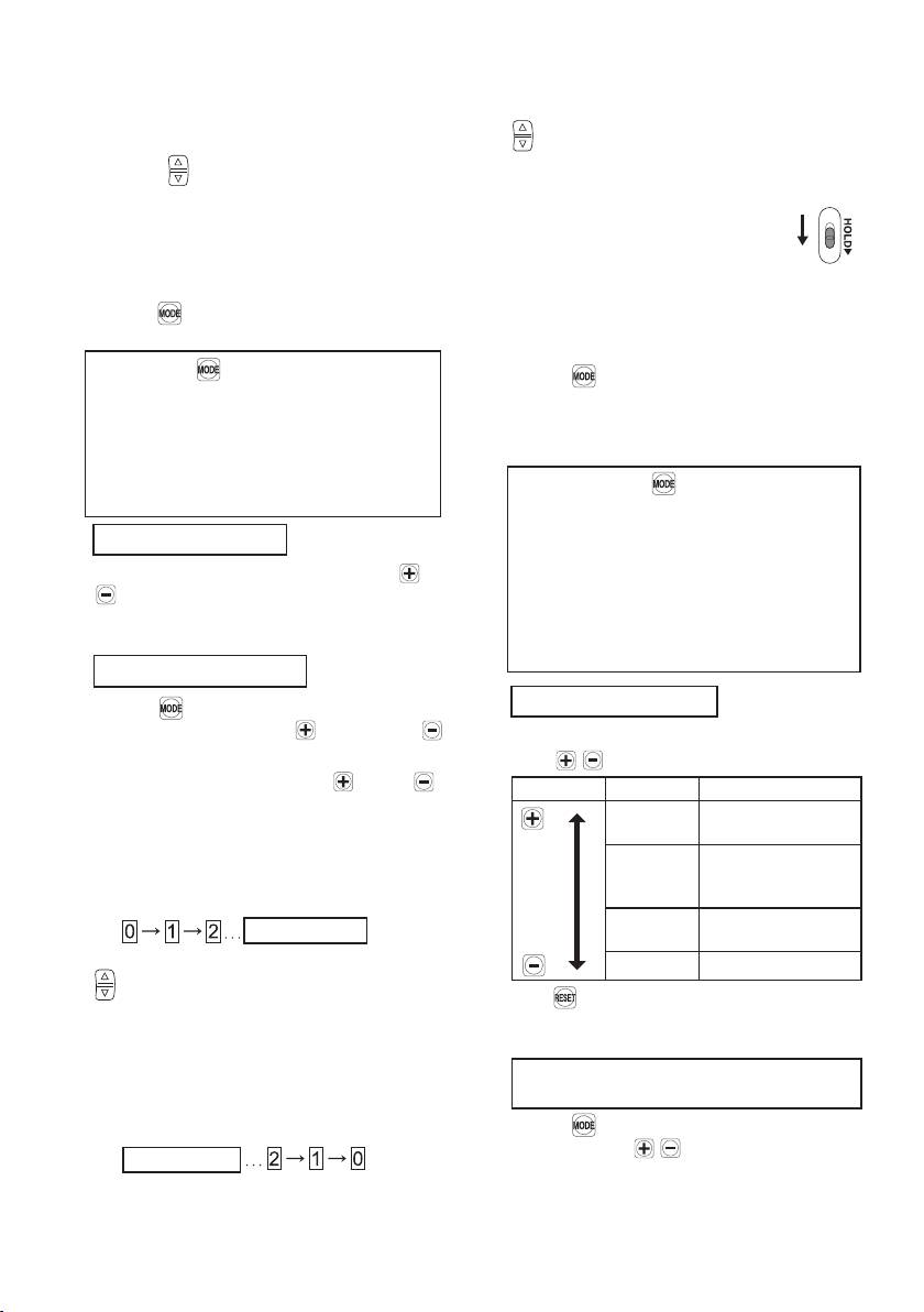
Starting the control panel
sounds and the count value resets
to original set number.
1. Release the hold switch.
3. The settings are activated by pushing
2. To illuminate the control panel
.
1 Release the lock button
● The previous setting will be cleared.
2 Press (Control panel is lit.)
4. To prevent changes in the set values
● The count display lamp and “UP” or
due to operational errors.
“DOWN” are illuminated.
● Turn the HOLD switch
ON
Setting the count functions (Screw
to ON.
count setting/Count system setting)
Convenient function settings (buzzer
1.
Press while the control panel is
sound setting/double tightening
illuminated.
counting prevention time setting)
Each time is pressed, the screw
1.
Press for 2 or more seconds while
count setting and count system set-
the control panel is illuminated.
ting switch and flash.
● Count display lamp “F1” is illumi-
● Screw count setting
nated.
→Countdisplaylampflashes.
● Count system setting
Each time is pressed, the
→“UP”or“DOWN”flashes.
buzzer sound setting and double
tightening counting prevention time
2. Screw count setting
setting can be switched.
Set the number of screws with
or
● “Buzzer sound setting”
.
→“F1”isilluminated.
● The range can be set within 0 – 99.
● “Double tightening counting pre-
● 0 is not counted.
vention time setting”
→“F2”isilluminated.
Count system setting
2. Buzzer sound setting
Press
. “UP” or “DOWN” will begin
to flash. Next select (“UP”) or
The buzzer sound can be selected
(“DOWN”).
with when “F1” is illuminated.
● Press and hold the ( ) or ( )
Operation
Display Sound Frequency
buttons while setting the torque to
b3 High pitched sound
vary the value continuously.
(Approx. 4 kHz)
< Count System “UP” >
b2
Medium pitched
sound (Approx. 3
● Displays the count for the number
kHz)
of screws driven.
b1 Low pitched sound
(
Set number
)
(Approx. 2 kHz)
The settings are activated by pushing
b0 No sound (OFF)
.
● If is pressed, the buzzer sound
● When the set number of screws is
saved from the previous setting is
reached, the buzzer sounds and
displayed.
the count value resets to zero.
Double tightening counting preven-
< Count System “DOWN” >
tion time setting
● Displays the count for the remain-
Press
to illuminate “F2” and select
ing number of screws to be driven.
the time with .
(
)
Set number
● When the set number of screws to
be driven is reached, the buzzer
-
8
-
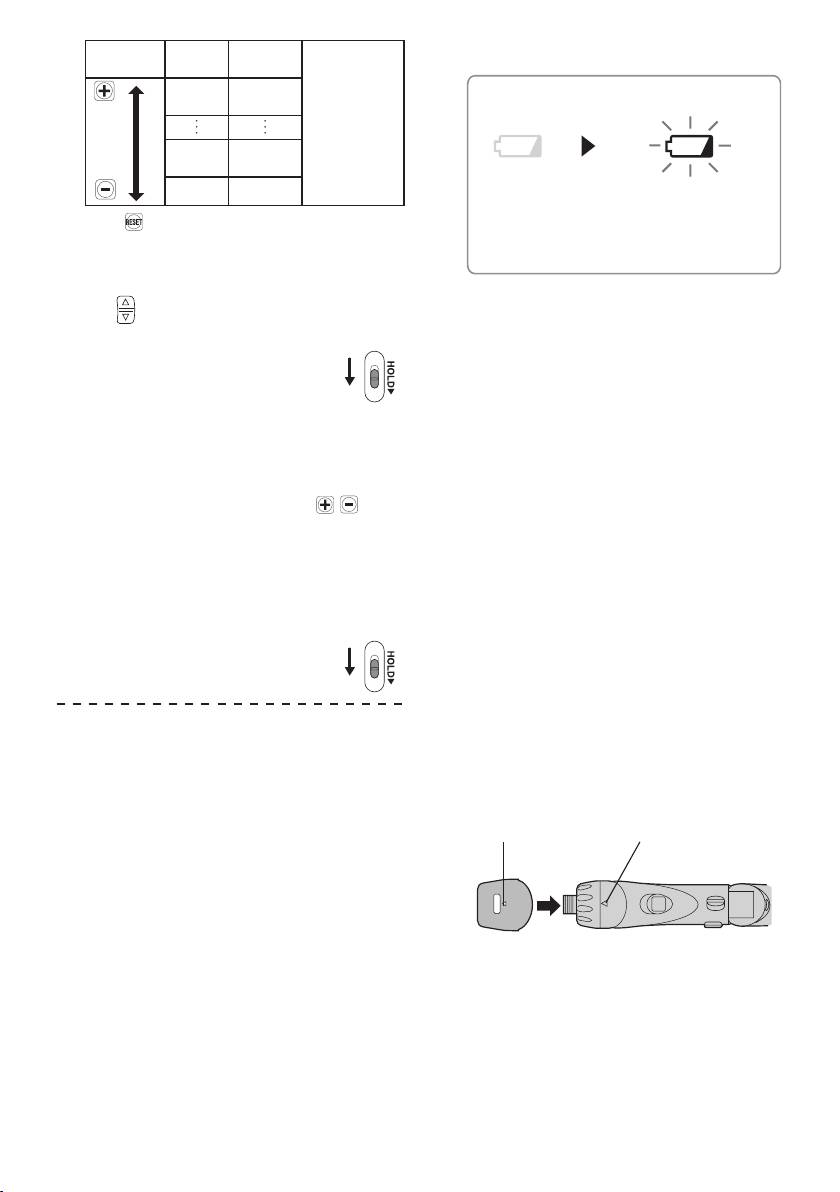
No. of
Following the
Battery Low Warning Lamp
Operation Display
seconds
screw count,
30 3
screw driving
seconds
within the set
number of
seconds is
1 0.1
not counted.
second
0 OFF
● If is pressed, the time setting
saved from the previous setting is
displayed.
3. The settings are activated by press
-
ing .
4. To prevent changes in the set values
due to operational errors.
● Turn the HOLD switch
ON
to ON.
To change the screw count while in
use
1. Release the hold switch.
2. Adjust the count value with
.
● The displayed number of screws
to be driven can be changed within
the range of the screw count val-
ues.
3. To prevent changes in the set values
due to operational errors.
● Turn the HOLD switch
to ON.
ON
■ While setting, if no operations are
conducted for 60 or more seconds
and when the battery is removed
● Operation for the set value be-
comes invalid.
Pleas e reset the operational
values.
■ Whenbatteriesarechangedwhilein
use
● When batteries are changed, the
count value is saved. Therefore,
the drill can be used continuously.
-
9
-
<Battery low warning lamp>
Off
Flashing
(normal
(No charge)
operation)
Battery
protection
feature active
Excessive (complete) discharging of
Li-ion batteries shortens their service
life dramatically. The driver includes a
battery protection feature designed to
prevent excessive discharging of the
battery pack.
●The batteryprotection featureacti
-
vates immediately before the bat-
tery loses its charge, causing the
battery low warning lamp to flash.
●If you notice thebattery low warn
-
ing lamp flashing, charge the bat-
tery pack immediately.
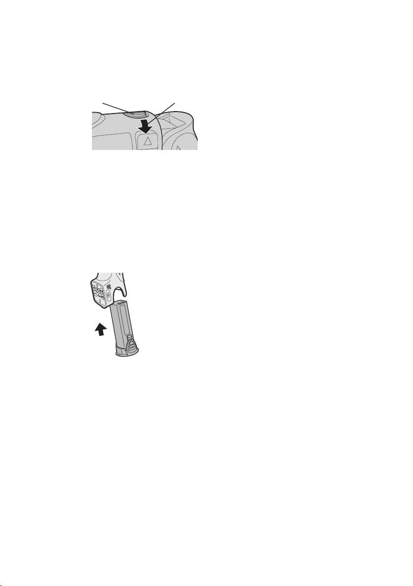
Clutch Lock Cover
The clutch lock cover allows you to
lock the clutch at the selected setting.
Attaching the cover
1. Select the appropriate clutch set
-
ting for the application.
2. Attach the clutch lock cover.
●Align the triangle mark on the
cover with the graduation selec-
tion mark on the drill and attach.
Triangle mark Graduation selection
mark
Removing the cover
1. Grip the clutch lock cover with your
fingers on the mark and the bot-
tom of the cover, then push in and
twist to remove.
Bit-locking Function
With the switch at off and the bit lock-
ed in place, the tool can be used as a
manual screw-driver - up to 14.7 N·m
(150 kgf-cm, 130 in-lbs).
There will be a little play in the driving
●Itwill bedifficult toremove the
shaft, but this is not a malfunction.
clutch lock cover from the drill if
you push on the side of the cover
while pulling it off.
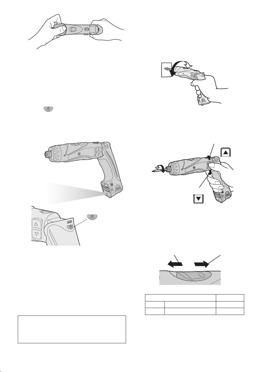
Using the LED Light
Before the use of LED light, always
pull the power switch once.
Press the LED light on button.
The light illuminates with very low cur-
Main Switch (ON/OFF)
rent, and it does not adversely affect
Push the upper half of the switch for
the performance of the tool during
forward rotation, or the lower half for
use or its battery capacity.
reverse rotation.
Forward
Forward
Reverse
Reverse
Speed Selector Switch
To suit the application of this tool, two
different rotational speeds are avail-
able. Depending upon use, either the
high or low speed should be select-
ed.
HIGH
LOW
CAUTION:
• The built-in LED light is designed
to illuminate the small work area
temporarily.
• Do not use it as a substitute for a
regularashlight,sinceitdoesnot
have enough brightness.
Speed selection Torque
• LED light turns off when the tool
-1
LOW 200 min
(rpm) High
has not been used for 5 minutes.
-1
HIGH 600 min
(rpm) Low
Caution : DO NOT STARE INTO BEAM.
CAUTION:
Use of controls or adjustments or performance
• Check speed selector switch before
ofproceduresotherthanthosespeciedherein
use.
may result in hazardous radiation exposure.
• Do not operate the speed selector
-
10
-
switch while the main switch is on
(32°F), the tool may fail to function
(switch is in the ON position).
properly.
• When battery pack is not in use,
Main Switch Lock
keep it away from other metal objects
After use, set the main switch lock at
like: paper clips, coins, keys, nails,
the lock position to prevent accidental
screws, or other small metal objects
operation.
that can make a connection from one
terminal to another.
Lock
Main switch lock
Shorting the battery terminals togeth
-
er may cause sparks, burns or a fire.
•
When operating the battery pack,
make sure the work place is well ven-
tilated.
Battery Pack Life
Battery Pack (EY9L10)
The rechargeable batteries have
1. Remove the battery pack away from
a limited life. If the operation time
the tool.
becomes extremely short after
2. Charge the battery pack using the
recharging, replace the battery pack
battery charger.
with a new one.
3. After charging has been completed,
remove the battery pack from the
Battery Recycling
charger and connect it to the tool.
ATTENTION:
Disconnect the charger from the
For environmental protection and
power source when not in use.
recycling of materials, be sure
that it is disposed of at an officially
assigned location, if there is one in
your country.
[Battery Charger]
Charging
Common Cautions for the Li-
NOTE:
ion/Ni-Cd Battery Pack
Use under extremely hot or cold
conditions will reduce operating
NOTE:
capacity per charge.
• When a cold battery (of about 0°C
or less) is to be charged in a warm
room, leave the battery in the room
[Battery Pack]
for at least one hour and charge
it when it has warmed up to room
For Appropriate Use of Bat-
temperature. (Failing to do so may
tery pack
result in less than a full charge.)
•
Cool down the charger when charging
Li-ion Battery pack (EY9L10)
more than two battery packs consecu-
• For optimum battery life, store the Li-
tively.
ion battery pack following use without
• Do not insert your fingers into con-
charging it.
tact hole, when holding charger or
•
The ambient temperature range is
any other occasions.
between 0°C (32°F) and 40°C (104°F).
CAUTION:
If the battery pack is used when the
To prevent the risk of fire or damage
battery temperature is below 0°C
to the battery charger.
-
11
-
• Do not use power source from an
6.
When charging is completed, the
engine generator.
charging lamp will start flashing quickly
• Do not cover vent holes on the
in green color.
charger and the battery pack.
7. If the temperature of the battery pack
• Unplug the charger when not in
is 0°C or less, charging takes longer to
use.
fully charge the battery pack than the
standard charging time. Even when
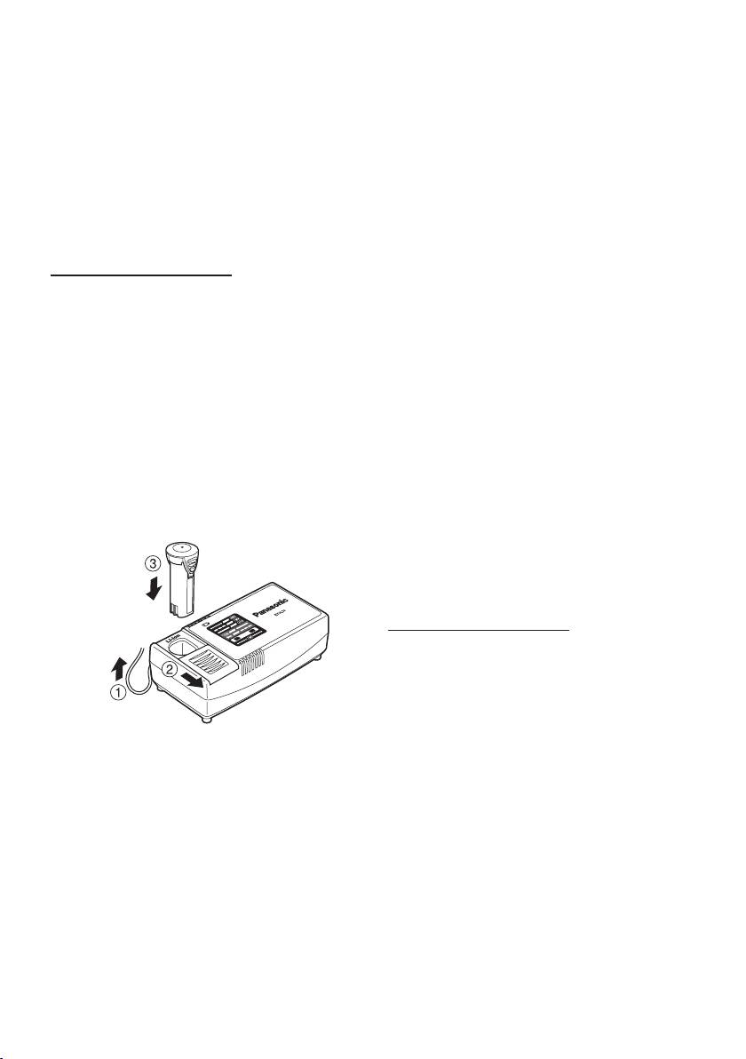
Li-ion Battery Pack
the battery is fully charged, it will have
NOTE:
approximately 50% of the power of a
Your battery pack is not fully charg-
fully charged battery at normal operat-
ed at the time of purchase. Be sure
ing temperature.
to charge the battery before use.
8. If the power lamp does not light im-
Battery charger (EY0L10)
mediately after the charger is plugged
in, or if after the standard charging
1. Plug the charger into the AC outlet.
time the charging lamp does not flash
NOTE:
quickly in green, consult an authorized
Sparks may be produced when the
dealer.
plug is inserted into the AC power
9. If a fully charged battery pack is in-
supply, but this is not a problem in
serted into the charger again, the
terms of safety.
charging lamp lights up. After several
minutes, the charging lamp may flash
2. Slide the battery dock cover back to
quickly to indicate the charging is
allow insertion of the Li-ion battery
completed.
pack.
●Verify that thecoverislocked se-
Ni-Cd Battery Pack
curely in place.
NOTE:
3. Insert the battery pack firmly into the
When you charge the battery pack
charger.
for the first time, or after prolonged
storage, charge it for about 24
hours to bring the battery up to full
capacity.
To AC
outlet
Battery charger (EY0L10)
1. Plug the charger into the AC outlet.
NOTE:
Sparks may be produced when the
plug is inserted into the AC power
supply, but this is not a problem in
4. During charging, the charging lamp
terms of safety.
will be lit.
When charging is completed, an inter-
2. Slide the battery dock cover back to
nal electronic switch will automatically
allow insertion of the Ni-Cd battery
be triggered to prevent overcharging.
pack.
• Charging will not start if the battery
●Verifythatthecoverislockedsecurely
pack is warm (for example, immedi-
in place.
ately after heavy-duty operation).
3. Insert the battery pack firmly into the
The orange standby lamp will be
charger.
flashing until the battery cools down.
Charging will then begin automati
-
cally.
5.
The charge lamp (green) will flash
slowly once the battery is approxi-
mately 80% charged.
-
12
-
5.
When charging is completed, the
To AC
charging
lamp will start flashing quick-
outlet
ly in green color.
6. If the power lamp does not light im
-
mediately after the charger is plug-
ged in, or if after the standard charg-
ing time the charging lamp does not
flash quickly in green, consult an au-
thorized dealer.
4.
During charging, the charging lamp will
be lit.
7. If a fully charged battery pack is in-
When charging is completed, an inter-
serted into the charger again, the
nal electronic switch will automatically
charging lamp lights up. After several
be triggered to prevent overcharging.
minutes, the charging lamp may flash
• Charging will not start if the battery
quickly to indicate the charging is
pack is warm (for example, immedi-
completed.
ately after heavy-duty operation).
The orange standby lamp will be
flashing until the battery cools down.
Charging will then begin automati-
cally.
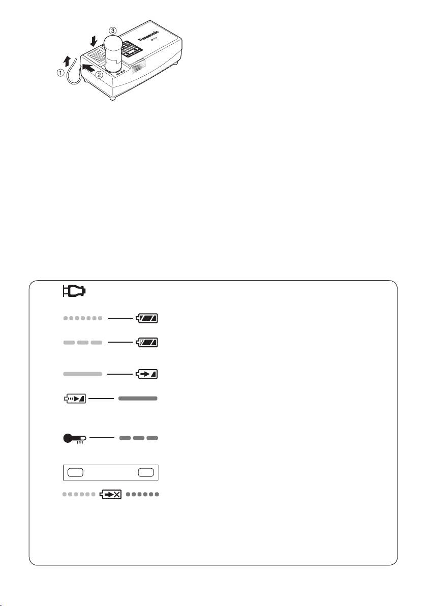
LAMP INDICATIONS
Green Lit
Charger is plugged into the AC outlet.
Ready to charge.
Green Flashing Quickly
Charging is completed. (Full charge.)
Green Flashing
Battery is approximately 80% charged. (Usable charge.
Li-ion only)
Green Lit
Now charging.
Orange Lit
Battery pack is cool.
The battery pack is being charged slowly to reduce the
load on the battery. (Li-ion only)
Orange Flashing
Battery pack is warm. Charging will begin when temper-
ature of battery pack drops.
Charging Status Lamp
Left: green Right: orange will be displayed.
Both Orange and Green Flashing Quickly
Charging is not possible. Clogged with dust or malfunc-
tion of the battery pack.
If the temperature of the battery pack is –10°C or less,
thechargingstatuslamp(orange)willalsostartashing.
Charging will begin when the temperature of the battery
pack goes up (Li-ion only)
-
13
-
