Alexika RV 10 control V-C auto – page 3
Manual for Alexika RV 10 control V-C auto

41
•
Unpacking
- Please unpack the device carefully
- In the case of any damage a fact report must be sent immediately
(post, rail or forwarder)
•
Delivery scope
see table
Useful information
The device is equipped with a piston-operated safety mechanism. The
glass apparatus may contain a vacuum following interruption to the po-
wer supply; vent the system before switching back on. If the power cuts
out, the evaporator piston is automatically lifted out of the heating bath
by an integrated gas spring.
CAUTION!
The safety lift must be checked daily prior to operation. For
more information see the section entitled "Safety Instructions - Safety
Lift"!
In addition to offering a full range of manual and semi-automatic evapo-
ration operating modes, the RV 10 control rotary evaporator can also be
used for fully automatic and quantity-controlled evaporation processes.
Standard fittings for fully-automatic operation include a vacuum cont-
roller, a cooling water differential temperature measurement sensor and
a cooling water flow rate meter. The vacuum can be controlled in both
two-position and speed-controlled pumping operation with the help of
the integrated vacuum controller The device is designed for operation
with a cooling water supply system (e.g. laboratory thermostat), but can
also be run off a water supply line. Please refer to the Technical Data for
information on cooling water pressure, temperature constancy, flow rate
and local regulations.
We recommend using the RV 10.5001 water regulator valve when ope-
rating directly off a water supply line.
This valve allows the cooling water flow rate to be adjusted and automa-
tically cuts off the cooling water supply on completion of the distillation
process.
The RV 10.5002 water filter can be used to prevent particles of dirt pas-
sing from the water supply line into the valve mechanism.
If pressure reduction is required, we recommend fitting the RV 10.5003
pressure regulator valve in the pipe immediately downstream of the pick-
off point.
Automatic volume-dependent distillation:
The apparatus must be
brought up to operating temperature. This is achieved by conducting a
test distillation.
Distillation is a thermal separating process for liquid compounds based
on substance-specific, pressure-dependent boiling points through evapo-
ration and subsequent condensation.
The boiling point temperature decreases with decreasing external pressu-
re which means that work is usually done under reduced pressure. In this
way the heating bath can be maintained at a constant temperature (e.g.
60 °C). Using the vacuum, the boiling point is set with a steam tempe-
rature of approx. 40 °C. The cooling water for the condensation cooler
should not be warmer than 20 °C (60-40-20 rule).
A chemical resistant membrane pump with a vacuum controller should
be used to create the vacuum. The pump is protected from solvent resi-
due by the addition of a Woulff bottle and/or a vacuum separator.
Working with a jet pump to create a vacuum can only be recommended
to a limited extent as the solvents may contaminate the environment
when using these systems.
Speed, temperature, piston size and system pressure all affect the eva-
porator air capacity.
The optimum capacity of the flow-through condenser is approx. 60%.
This corresponds to condensation on approx. 2/3 of the cooling coil.
With larger capacities there is the risk that the uncondensed solvent va-
pour will be extracted.
In order to prevent this, the condenser loading safety monitoring system
can be activated. Before activating the safety monitoring, first carry out
several distillations, noting the value given under menu “Settings”, menu
option “Drive”, item “Maximum heat rejection rate”. Now calculate the
heat rejection rate using the following formula:
Heat rejection rate threshold = maximum heat rejection rate * 1.3
Enter this value under menu “Settings”, menu option “Distillation”, item
“Heat rejection rate threshold”. The device will now stop the measure-
ment and issue an error message if the threshold for the condenser is
exceeded. If the configuration of the condenser equipment or the dis-
tillation process is modified, then it may be necessary to re-evaluate the
maximum condenser loading.
The factory setting for this value is 900 W.
Unpacking
RV
10
control
V
x x x x x x x x x x x x
RV
10
control
V-C x x x x x x x x x x x x
RV
10
control
FLEX x x x x x x x x x x x
RV
10
control
V
auto x x x x x x x x x x x x
RV
10
control
V-C
auto x x x x x x x x x x x x
RV
10
control
FLEX
auto x x x x x x x x x x x
Drive RV 10 contr
ol
Heating bath HB 10
Vertical glasswar
e RV 10.1
Vertical glasswar
e RV 10.10 coated
W
oulff bottle
Br
acket
Cooler locking device, compl.
Vacuum hose (2 x 0.55 m)
W
ater dischar
ge hose (1 x 1 m)
Oper
ating instructions
Ring spanner
Hand
hold
RV 10.4002 vacuum valve for labor
atory vacuum system
N 920 speed-contr
ol
led vacuum pump

42
The RV 10 control rotary evaporator allows you to set the desired vacuum using two-position and speed control with the help of the integrated va-
cuum controller and pressure sensor.
Two-position control
A vacuum is made in the glassware with the help of a vacuum pump. The vacuum pump operates at constant speed which generally cannot be ad-
justed. Once the target value setting is reached, the RV 10.4002 vacuum valve interrupts the suction line (included in scope of supply). If additional
switching on and off of the vacuum pump is desired, please use the RV 10.4003 pump control (accessory).
The device will fall slightly short of the target value setting due to the time difference in the millisecond range with the vacuum value, the target value
comparison and the switching of the vacuum valve. Natural leakage from the apparatus now causes another increase in the pressure value of the
system, which in turn is detected by the integrated pressure sensor.
If the target value is exceeded, the vacuum valve is reopened and the vacuum pump in operation lowers the pressure. The pressure curve shown on
the display fluctuates around the set target value.
The pressure difference between activating/deactivating the valve can be set using the vacuum hysteresis value (see Vacuum Settings). The value is set
to 10 mbar as standard.
The quality of the control depends on the suction power of the pump (rotation speed), the tightness of the system and signal delay time of the elec-
tronics used.
Automatic boiling point recognition is not possible when using two-position control.
Schematic view of a two-position vacuum control
Speed-vacuum control
Imprecision of the two-position control is avoided by using the speed-vacuum control.
However a vacuum pump with a controlled speed is needed for speed-vacuum control; the RV10.4002 vacuum valve is not required and must not
be connected!
To do so, connect the vacuum pump (e.g. KNF N920 speed controlled pump) to the port on the rear of the rotary evaporator.
With this kind of control, the speed of the pump, and therefore its suction power, is reduced the closer the measured pressure reaches the target value.
Once the target value is reached, the pump only operates according to the leakage rate.
It is possible to achieve quieter operation and more exact vacuum control.
The speed-vacuum control on the RV 10 is controlled automatically as soon as an appropriate vacuum pump is attached.
Automatic boiling point recognition is possible with this type of control, i.e. the system reaches and keeps the solvent at its boiling point in automatic
mode.
As it is not necessary to know the boiling point of the solvent when in automatic boiling point recognition mode (unlike in the case of volume-depen-
dent distillation), these two operating modes are mutually exclusive.
Schematic view of speed-vacuum control
Vacuum control: two-position and speed control

43
Setting up
Remove the clamping device for the angle setting of the rotation drive
on the right side of the lift by rotating the knurled screw counter clock-
wise (by lightly pressing and turning at the same time, the knurled
screw comes out farther).
Set the drive at an angle of approx. 30° (Fig. 7).
Then secure the rotation drive from being accidentally turned by tigh-
tening the knurled screw in a clockwise direction.
Heating bath HB 10
Caution!
Refer to the chapter entitled "Commissioning" in the heating
bath instruction manual!
Place the heating bath on the stand of the rotation drive and push it
into the left position (Fig. 8).
Note: Data is exchanged between the drive unit and the heating bath by
means of an infrared link (F). Please note that reliable communication is
only guaranteed when the infrared beam has clear line-of-sight to the
detector.
Glassware
Open the locking device of the steam pipe by turning it 60° counter
clockwise (D), (fig. 9).
Drive RV 10 control
Caution!
Loosen transportation lock (Fig. 4a)!
Hold the lift with your hand and remove the thumb screw on the back
of the appliance (A).
Once the transportation lock has been removed, the lift moves slowly
to its upper end position. The distance is approx. 140 mm.
Connect the device to the power supply (B) using the supplied power
cord (B).
Adjustable base (Fig. 4b)
Mounting the Woulff bottle (Fig. 5)
Fit the hose connecting piece (C) on the left side of the lift.
Mount the holder (D) onto the hose connecting piece (C).
Insert the bottle and attach the supplied hose connectors to the bottle
(Fig. 6).
Fig. 4a
Fig. 4b
E
G
H
Fig. 7
Fig. 9
Fig. 5
Fig. 6
C
D
Fig. 8
F
44
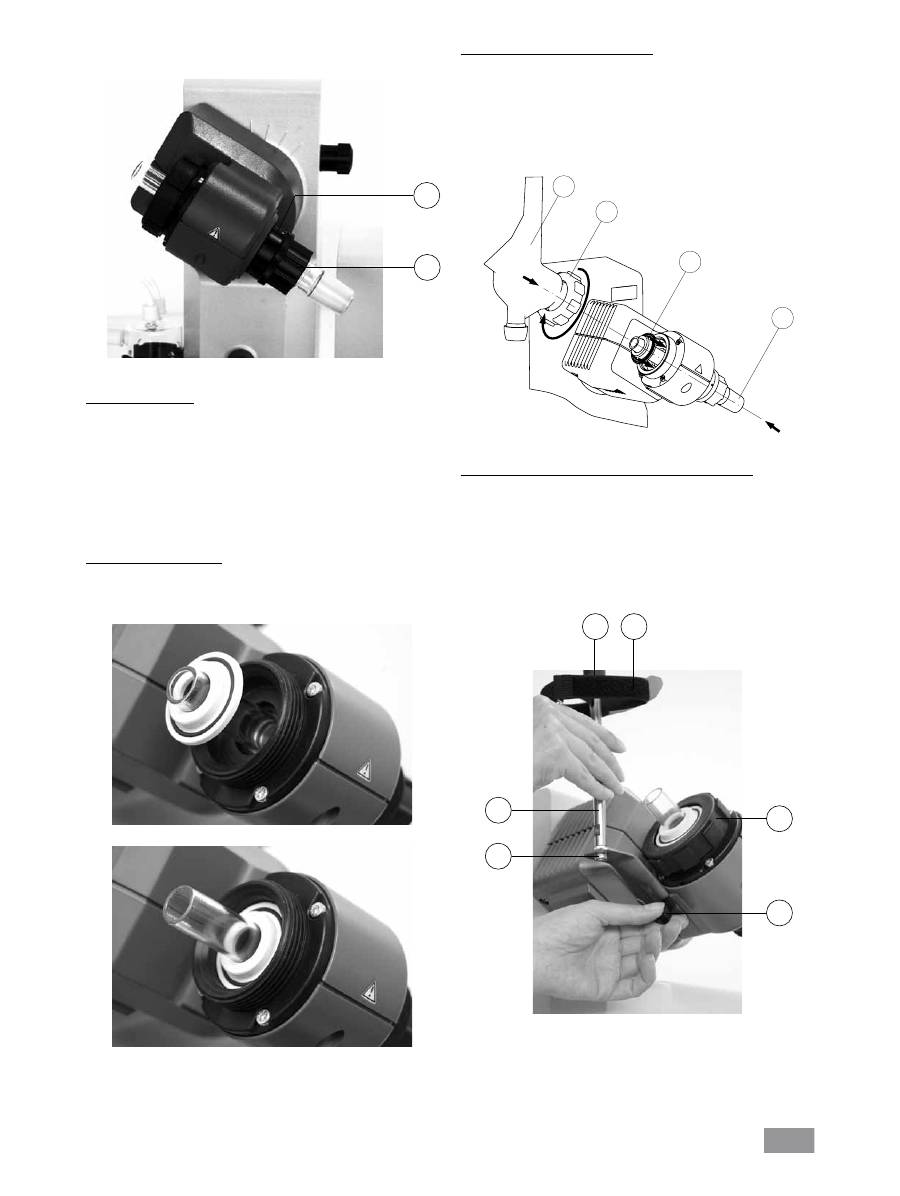
First use - Fitting the seal RV 10.8001
Insert vapour tube (1).
Insert seal RV 10.8001 (2).
Slide the union nut (3b) over the flange on the condenser (3a).
Also slide the annular spring (3c) over the flange on the condenser (3a).
Position the condenser (3a) on top of the seal (2).
Tighten the cap nut hand-screwed (3b).
Note: Follow the mounting instructions for the glassware
Assembling the vertical glassware cooler locking device
Assemble the condenser locking device according to the diagram (fig.
12).
Mount the plate (I) using the thumb screw (J).
Put the support rod (L) on the plate (I) and attach it with the screw
nut (K).
Attach the rubber protector (M).
Fasten the Velcro
®
band (N) to the support rod (L).
Secure the vertical glassware with the Velcro
®
band (N).
Feed the steam pipe in until it stops.
Then lock the locking device by turning it clockwise by 60° (Fig. 10).
Check the axial locking device on the steam pipe.
Push-off mechanism
The plastic screw nut (H) helps loosen tight-fitting piston ground-in con-
nections (Fig. 10).
Hold the locking device (G) and loosen the plastic screw nut (H).
To do so, hold the tight-fitting evaporator piston and turn the plastic
screw nut (H) until the evaporator piston neck.
Note: Prior to commissioning, hand-tighten the plastic screw nut (H) left-
aligned. This will hold the steam pipe locking device (G) firmly in place.
Fitting the condenser seal
Place the RV 10.8001 condenser seal in the condenser receptacle and
fit the glassware to the device according to the assembly instructions
(Fig. 11 a,b, c and d).
Fig. 10
H
Fig. 11a
Fig. 11b
1
2
3a
3b
Fig. 11c
Fig. 12
I
J
M
N
L
K
G

45
4
7
8
6
12
9
3
10
5
13
15
16
Rotary head
Glassware
RV 10.2 diagonal
RV 10.20 diagonal, coated
Glassware
RV 10.1 vertical
RV 10.10 vertical, coated
Rotary head
2
10
00
m
l
N
S2
9/
32
1
11
13
12
5
4
7
8
6
15
9
3
2
10
16
11
1
10
00
m
l
N
S2
9/
32
Glassware
Item Designation
Quantity
Quantity
diagonal glassware
vertical Glassware
1
Receiving flask
1
1
2
Clamp NS 29 (stainless steel)
1
1
3
Steam pipe
1
1
4 Stopcock
1
1
5
Pipe tube
1
1
6
Condenser
1 Diagonal condenser
1 Vertical condenser
7
Connection
1 Introduction sleeve
1 Vacuum connection
8
Clamp NS 29 (plastic)
1
1
9
Seal RV 10.8001
1
1
10
Evaporator piston 1000 ml
1
1
11
Ball joint clamp RV 05.10
1
1
12
Screw joint cap
4
4
13
Hose connection
4
4
15
Locking nut
1
1
16
Spring ring
1
1
Description of special condensers
•
RV 10.3 Vertical-intensive condenser with manifold
This vertical-intensive condenser features a double jacket design for
particularly efficient condensation.
Also available with coating (RV 10.30)
•
RV 10.4 Dry ice condenser
Dry ice condenser for distilling low-boiling solvents.
Cooling by dry ice, no cooling water required. Maximum condensation
thanks to low temperatures.
Also available with coating (RV 10.40)
(Cannot be used in automatic mode for the RV10 control)
•
RV 10.5 Vertical-condenser with manifold and cut-off valve for
reflux distillation
Also available with coating (RV 10.50)
•
RV 10.6 Vertical-intensive condenser with manifold and cut-off
valve for reflux distillation
This vertical-intensive action condenser features a double jacket design
for particularly efficient reflux distillation.
Also available with coating (RV 10.60)
Removing the condenser
Use the ring spanner provided to loosen union nuts that are tightly
fitted.
Loosen the union nut by turning anticlockwise.
Remove the Velcro
®
.
Fig. 13
Mounting the glassware
46
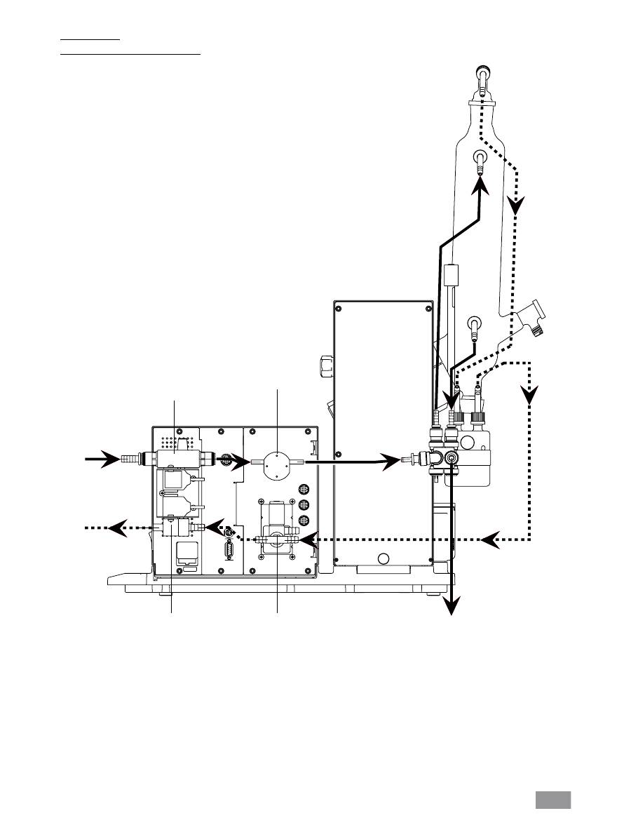
Hose system
Schematic view of hose system (rear view)
2x T1,6A 250V
Water
Vacuum
RV 10.5001
Water regulator
valve,
optional
Flow meter
Water
Pressure sensor
and
bleed valve
RV 10.4002
Vacuum valve
Fig. 14

47
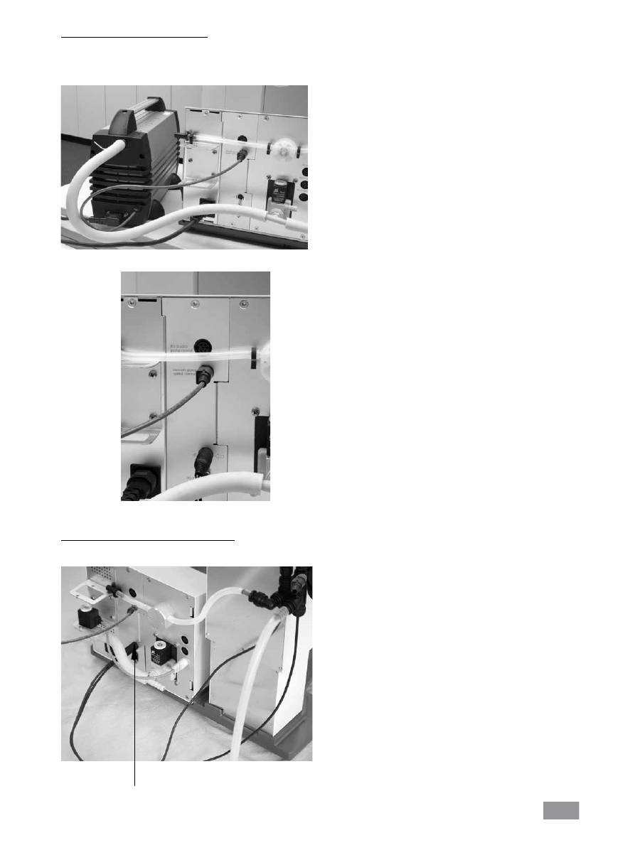
Connection RV 10.4003
Vacuum - two-position control
Fit one of the optional RV 10.4001, RV 10.4002 or RV1 0.4003 vacu-
um valves, as appropriate for the type of vacuum system used, in the
bracket provided for this purpose and connect the vacuum hose to the
valve (Figure 15a, b, c).
Connection RV 10.4001
Connection RV 10.4002
Solenoid rotates freely
Direction of suction
corresponds to the arrow
marking.
Always check for correct
orientation!
Fig. 15a
Solenoid rotates freely
Direction of suction
corresponds to the arrow
marking.
Always check for correct
orientation!
Fig. 15b
Solenoid rotates freely
Direction of suction
corresponds to the arrow
marking.
Always check for correct
orientation!
Fig. 15c
Power supply
pump
48
Vacuum - speed-controlled operation
No additional valve is required for vacuum normal operation with a
speed-controlled pump. Connect the pump's vacuum hose directly to
the pressure sensor hose connection.
Connect the electrical RV10 control cable to the controller (Fig. 15e).
Connection RV 10 temperature sensor ( (dT)
Connect the temperature sensor to the lower socket (dT). Always check
for correct direction of the arrow.
Fig. 15f
dT
Fig. 15d
Fig. 15e

49
Connect the water outlet hose (supplied) by pushing it onto the nipple
until the stop inside the connection socket is reached (fig. 18).
Caution!
Ensure that the condenser inlet and condenser outlet are con-
nected correctly.
Automatic distillation cannot be carried out if the water inlet and outlet
hoses are not fitted according to the instructions and illustrations acc.
fig. 14, since this would cause the temperature readings for the inlet and
outlet to be measured incorrectly.
Release the hose connection using the supplied tool.
Water
Connect the water inlet to the water supply (Figure 16a; Figure 16b with
optional RV 10.5001 water regulator valve). Please refer to the technical
specifications relating to the water supply.
The RV 10.5001 water regulator valve is not suitable for use on the
condenser unit because it would reduce the flow rate too greatly
Connect the water hoses to the glass condenser (short hose (O) = lower
outlet, long hose (P) = upper inlet) and fix hoses in place (fig. 17).
Note: For special condensers see “Description of special condensers” section.
Fig. 16a
Fig. 16b
Fig. 17
O
P
Fig. 18
Fig. 19
Inlet
condenser
Outlet
condenser
Water
inlet
Water
inlet

50
Schematic view of connections (rear view)
Insert the valve connector cable (RV 10.5001 or RV 10.4001/2 resp. RV 10.4003 Valve) resp. the network cable (RV 10.4003 pump control) ) into the
appropriate socket (fig. 20) or connect the speed-regulated vacuum pump. As a result, the RV10 control automatically switches to normal speed-vacuum
control operation.
Fig. 20
Connect the pressure sensor to the Woulff bottle and the Woulff bottle
to the vacuum connector on the condenser using the vacuum hoses
supplied. Please note that the vacuum must always be connected to the
highest connection point on the condenser (fig. 21).
Fig. 21

51
Serial interface RS 232 (V24)
Configuration
- The functions of the interface lines between the device and the au-
tomation system are a selection from the signals specified in the EIA
standard RS232 C, as per DIN 66 020 Part 1.
- For the electrical characteristics of the interface and the allocation of
signal status, standard RS 232 C applies in accordance with DIN 66
259 part 1.
- Transmission procedure: asynchronous character transmission in start-
stop mode.
- Type of transmission: full duplex.
- Character format: character representation in accordance with data for-
mat in DIN 66 022 for start-stop mode. 1 start bit; 7 character bits; 1
parity bit (even); 1 stop bit.
- Transmission speed: 9600 bit/s.
- Data flow control: none
- Access procedure: data transfer from the device to the computer takes
place only at the computer’s request.
Command syntax and format
The following applies to the command set:
- Commands are generally sent from the computer (Master) to the device
(Slave).
- The Rotary evaporator sends only at the computer’s request. Even fault
indications cannot be sent spontaneously from the Rotary evaporator to
the computer (automation system).
- Commands are transmitted in capital letters.
- Commands and parameters including successive parameters are separa-
ted by at least one space (Code: hex 0x20).
- Each individual command (incl. parameters and data) and each response
are terminated with Blank CR LF (Code: hex 0x20 hex 0x0d hex 0x20 hex
0x0A) and have a maximum length of 80 characters.
- The decimal separator in a number is a dot (Code: hex 0X20E).
The above details correspond as far as possible to the recommendations
of the NAMUR working party (NAMUR recommendations for the design of
electrical plug connections for analogue and digital signal transmission on
individual items of laboratory control equipment, rev. 1.1).
The NAMUR commands and the additional specific
IKA
®
co mmands serve
only as low level commands for communication between the rotary eva-
porator and the PC. With a suitable terminal or communications program-
me these commands can be transmitted directly to the rotary evaporator.
The
IKA
®
software package, labworldsoft, provides a convenient tool for
controlling rotary evaporator and collecting data under MS Windows, and
includes graphical entry features, for motor speed ramps for example.
The following table summarises the (NAMUR) commands understood by
the
IKA
®
control equipment.
HB 10
Data is exchanged between the heating bath and the drive unit by means
of an infrared link. These are located on the left display side of the hea-
ting bath or on the right side of the drive unit. Do not place any objects
between the two operating units as otherwise the data transfer may be
interrupted (fig. 22)!
RV10 control
The device can be operated in “Remote” mode via an RS 232 or USB
interface using labworldsoft
®
laboratory software.
The RS 232 interface at the back of the device, see fig. 20, is fitted with
a 9-pole SUB-D jack and can be connected to a PC. The pins have serial
signals. The USB interface is located on the left-hand side of the display
on the drive unit and can be connected to a PC using the USB cable
supplied.
Note: Please note the system requirements as well as the operating ins-
tructions and help section included with the software.
USB Interface
The Universal Serial Bus (USB) is a serial bus system used to connect the
RV 10 control with the PC (Fig. 23). Devices that support USB can be con-
nected to each other whilst they are running (hot pluggable) and provide
automatic recognition of the connected devices and their properties.
Use the USB interface in conjunction with labworldsoft
®
for operation in
“Remote” mode to update the solvent library. Navigate to http://www.
ika.net/ika/lws/download/RV10.cfg to update.
Installation
Connect the RV 10 control to the PC using the USB data cable. The RV 10
control will then transmit information to the Windows operating system
to tell it which device drivers are required. Windows will then either:
- Load the driver,
- Install the driver automatically if not already installed,
- Prompt the user to perform a manual installation.
Navigate to http://www.ika.net/ika/lws/download/stmcdc.inf.
Interfaces and outputs
Fig. 22
IR
Fig. 23

52
Fig. 24
Abbreviations used:
m =
Numbering parameter (integer)
X =
2
Temperature heating bath
X =
3
Safety temperature heating bath
X =
4
Speed
X =
60
Interval time (1-99 seconds, 1 <= m >=99)
X =
61
Timer (1-199 minutes, 1 <= m >=199)
X =
62
Upper lift position (OUT_SP_62 1-> drive lift up)
X =
63
Lower lift position (OUT_SP_62 1-> drive lift down)
X =
66
Value vacuum controller
X =
70
Vacuum controller hysteresis
X =
74
Tempering medium (OUT_SP_74 0=Öl, OUT_SP_74 1=water)
NAMUR Commands Function
IN_NAME
Request designation
IN_PV_X
Read actual value
X = 4
IN_SOFTWARE
Request software Id-number,
date and version
IN_SP_X
Read target value input
X = 4
OUT_SP_X m
Set target value to m
X = 1,60,61,62
RESET
Switch to normal operation
START_X
Switch on appliance (remote) function
X = 4,60,61,62
STATUS
Status output
0:Manual operation without interruption
1:Automatic operation Start (without interruption)
ERROR z (z error number see table)
STOP_X
Switch off appliance function. The variable
X = 1,60, 61, 62
set with OUT_SP_X remains
PC 1.1 Cable (Fig. 24)
This cable is required to connect the 9-pin connector to a PC. (fig. 24).
.

53
Basic guide to using the menu system
Selecting a menu
Turn the Rotating/ Pressing knob to the right/left to select the desired
menu option.
Note: The active menu item is shown with a black background on the
display.
Editing values
Press the Rotating/ Pressing knob
Turn the Rotating/ Pressing knob to change the value (the magnitude
of the change is dependent on the speed at which the knob is turned).
Press the Rotating/ Pressing knob again to complete the process.
Exiting a menu
Press the SET button.
Current values are stored.
Next-highest menu level is displayed.
Press the ESC button.
Current values are not stored.
Next-highest menu level is displayed.
Note: Some menu items do not contain values that can be stored. Select
SET or ESC to exit the menu.
Note: Certain menu items have functionality that varies from or adds to
that described above.
Display screen during the distillation process
Each operating mode has its own dedicated display screen. The following
display characteristics are common:
- When a distillation is in progress it is not possible to leave the active
display indicated.
- Press SET or ESC to exit the active display mode when no distillation is in
progress. This will return the display to the main menu.
Error messages
Press ESC to acknowledge the fault if an error message appears on
the display.
The error message will disappear.
Note: In the case of serious faults, an additional display message will
appear indicating that the device must be switched off and only swit-
ched back on again when the fault has been rectified.
The unit is ready for service when the
mains plug has been plugged in.
Switching on the device
Switch on the device on the right side of the device by the mains plug
(fig.25).
Device functions activated.
Note: The heating bath must also be switched on.
Commissioning
Functional description (in as-delivered state)
Factory settings
The values specified below correspond to the as-delivered state (display
output/factory language setting is English)
The system check is performed while the start screen is displayed; this
takes no more than 30 seconds.
The main menu will appear after a few seconds.
Turn the Rotating/ Pressing knob to the right/left to select a menu
option.
Confirm the selection by pressing the Rotating/ Pressing knob.
“Settings“ menu
The following options are available from the "Settings" menu.
Turn the Rotating/ Pressing knob to the right/left to select a menu
option.
Confirm the selection by pressing the Rotating/ Pressing knob.
Fig. 25

54
Distillation settings
Turn the Rotating/ Pressing knob to the right/left to select a menu
option.
Press the Rotating/ Pressing knob.
Turn the Rotating/ Pressing knob to change the value (the magnitude
of the change is dependent on the speed at which the knob is turned).
Press the Rotating/ Pressing knob again to complete the process.
SET key: Exit menu and save changes.
ESC key: Exit menu without saving changes.
Distillation method
Select between the automatic distillation methods “Volume” and
“100%”. This selection only has an effect during auto-distillation.
Volume
The measured values of the cooling water flow rate and the cooling
water temperature difference form the basis for a heat balance calcu-
lation used to determine the quantity of distillate at every stage of the
distillation. The distillation process is halted when the specified quantity
of distillate has been reached.
100%
The distillation process is stopped when the measured cooling water
temperature difference falls below a threshold value, i.e. as soon as a
solvent has been completely distilled off.
Drying
The cooling water temperature difference is not monitored if this option
is activated, e.g. use in processes for drying powdered media.
Heat rejection rate threshold
A limit value can be set for the heat rejection rate that is appropria-
te for the condenser used; see "useful information" section. The actual
heat rejection rate is calculated during every distillation process. If the
threshold is exceeded, the distillation will be stopped and an error mes-
sage displayed.
Maximum heat rejection rate
The maximum heat rejection rate achieved during the last distillation is
displayed. This value is for information purposes only.
Quantity meas. unit
Select between millilitre and gram as the unit of quantity.
Boiling point recognition
Boiling point recognition can be either activated or deactivated. Boiling
point recognition is only possible in "100%" mode for the distillation
method.
The boiling point recognition function automatically detects the boiling
point of a solvent.
Vacuum settings
Turn the Rotating/ Pressing knob to the right/left to select a menu
option.
Press the Rotating/ Pressing knob.
Turn the Rotating/ Pressing knob to change the value (the magnitude
of the change is dependent on the speed at which the knob is turned).
Press the Rotating/ Pressing knob again to complete the process.
SET key: Exit menu and save changes.
ESC key: Exit menu without saving changes.
Hysteresis
The default settings for the hysteresis (as shown) are suitable for use in
most situations. The (vacuum) hysteresis value describes the difference
between the closing and opening pressures for the vacuum valve.
Time scaling
The time axis of the vacuum-rotation-time graph is scaled using the value
specified here. If the value = 0, then the time axis is scaled automatically.
Vacuum scaling
The vacuum axis of the vacuum-rotation-time graph is scaled using the
value specified here. If the value = 0, then the vacuum axis is scaled
automatically.
Vacuum meas. unit
Select between the units of measurement for a vacuum: mBar, Torr, and
hPascal.

55
Drive settings
Turn the Rotating/ Pressing knob to the right/left to select a menu
option.
Press the Rotating/ Pressing knob.
Turn the Rotating/ Pressing knob to change the value (the magnitude
of the change is dependent on the speed at which the knob is turned).
Press the Rotating/ Pressing knob again to complete the process.
SET key: Exit menu and save changes.
ESC key: Exit menu without saving changes.
Right/left interval
Setting a particular value X for the right/left interval will cause the drive
to change the direction of rotation every X seconds.
Note: In interval mode the maximum speed is limited to 200 rpm.
Timer
The timer value determines the time after which a manual distillation will
be stopped.
Time scaling
The time axis of the vacuum-rotation-time graph is scaled using the value
specified here. If the value = 0, then the time axis is scaled automatically.
Rotation scaling
The rotation axis of the vacuum-rotation-time graph is scaled using the
value specified here. If the value = 0, then the rotation axis is scaled
automatically.
Bath settings
Turn the Rotating/ Pressing knob to the right/left to select a menu
option.
Press the Rotating/ Pressing knob.
Turn the Rotating/ Pressing knob to change the value (the magnitude
of the change is dependent on the speed at which the knob is turned).
Press the Rotating/ Pressing knob again to complete the process.
SET key: Exit menu and save changes.
ESC key: Exit menu without saving changes.
Medium bath
Select either water or oil as the medium for the heating bath.
Language
Turn the Rotating/ Pressing knob to the left/right to select the lan-
guage.
Confirm the selection by pressing SET.

56
Service
Turn the Rotating/ Pressing knob to the right/left to select a menu
option.
Press the Rotating/ Pressing knob.
Turn the Rotating/ Pressing knob to change the value (the magnitude
of the change is dependent on the speed at which the knob is turned).
Press the Rotating/ Pressing knob again to complete the process.
ESC key: Exit menu, all changes to switch settings are reset, the calibra-
tion remains unaffected.
Switching valves and pump
To check functionality for servicing purposes, use the Service menu to
activate/deactivate directly the valves included in delivery or optional and
the pump, e.g. RV 10.5001.
The RV 10.5001 valve switches the water circuit on and off. This row also
shows the current cooling water flow rate.
Calibrate
The “Calibrate” option is used for calibration of the temperature sensor.
The temperature difference displayed will be calibrated to zero. This ac-
tion cannot be reversed.
The temperature sensor must be calibrated whenever it is replaced or
changed, or if a new temperature sensor is installed.
Please contact the Service department.
The temperature sensor supplied with the system is calibrated ex-works.
Performing calibration
Activate the “Calibrate” menu option by turning the Rotating/ Pressing
knob.
Remove both sensors. To remove a sensor, push back the outer ring to
release the locking device on the push-in connector, while at the same
time pulling the temperature sensor out of the connector, see fig. 26.
To reconnect a temperature sensor, push it into the push-in connector
until the limit stop is reached; an initial resistance will be felt.
Fill water at room ambient temperature into a glass beaker (approx.
500 ml). Fully submerge both sensors into the water, see fig. 27.
Wait until the temperature display in the “Service” menu, menu opti-
on “Calibrate” has stabilised, e.g. 0.2K
Press the Rotating/ Pressing knob.
The temperature difference displayed will be calibrated to zero.
Calibration is only possible within the temperature range +0.5 K to -0.5
K. If the temperature is outside this range, then either a temperature
sensor is faulty or connected incorrectly. Please contact the Service de-
partment.
If the characteristics of the cooling water supply deviate significantly
from the specifications given in the “Technical specifications”, with the
result that the initial conditions for automatic distillation are not achie-
ved, then it may be necessary to recalibrate the temperature sensors.
This may, however, lead to a reduction in the accuracy with which the
distillate quantity is measured in “Auto-distillation” mode.
Operation hours
This value serves as informaton and cannot be changed.
Fig. 26
Fig. 27

57
"Manual mode without boiling point recognition" menu
"Manual mode without boiling point recognition" display screen
1. Operating mode display
2. Vacuum display (actual value)
3. Vacuum display (target value)
4. Control field for „Start/ Stop“ distillation
5. Timer display
6. Control field for storing the distillation sequence
7. Vacuum-rotation-time graph
8. Display of flow rate, differential temperature, and condenser heat
rejection rate
9. Control field for rotary speed display (target value) and speed mea-
surement unit
10. Error message in case of fault, otherwise status indicator
Setting the rotary speed
Press the Rotating/ Pressing knob to change the target value.
Turn the Rotating/ Pressing knob to change the value (the magnitude
of the change is dependent on the speed at which the knob is turned).
Press the Rotating/ Pressing knob again to save and complete the
process.
Note: When you select the speed > 100 rpm, smooth start is automati-
cally activated.
Setting the vacuum
Press the Rotating/ Pressing knob to change the target value.
Turn the Rotating/ Pressing knob to change the value (the magnitude
of the change is dependent on the speed at which the knob is turned).
Press the Rotating/ Pressing knob again to save and complete the
process.
Start
Turn the Rotating/ Pressing knob to the right/left to select "Start".
Press the Rotating/ Pressing knob to start the distillation.
The display field will change to "Stop".
Note: If the timer has been configured, then the time will start to count
backwards. If a timer has not been configured then the time elapsed
since the start is shown.
Stop
Turn the Rotating/ Pressing knob to the right/left to select "Stop".
Press the Rotating/ Pressing knob to stop the distillation.
The display field will change to "Start".
Saving the distillation sequence as a procedure on completion of distillation
Turn the Rotating/ Pressing knob to the right/left to select "Save".
Press the Rotating/ Pressing knob to display the "Procedures" screen.
Turn the Rotating/ Pressing knob to the left/right to select one of the
ten procedures. The sequence will be shown graphically.
Press SET, to overwrite the selected procedure with the current proce-
dure (the procedure that has just been completed) and exit the menu.
Pressing ESC will prevent the selected procedure from being overwrit-
ten.
Note: Distillation sequences saved in this manner can be repeated at
a later dater in the user-defined mode by selecting the corresponding
procedure.

58
"Manual mode with boiling point recognition" menu
"Manual mode with boiling point recognition" display screen
1. Operating mode display
2. Vacuum display (actual value)
3. Vacuum display (target value)
4. Control field for „Start/ Stop“ distillation
5. Timer display
6. Control field for storing the distillation sequence
7. Vacuum-rotation-time graph
8. Display of flow rate, differential temperature, and condenser heat
rejection rate
9. Control field for rotary speed display (target value) and speed mea-
surement unit
10. Error message in case of fault, otherwise status indicator
Setting the rotary speed
Press the Rotating/ Pressing knob to change the target value.
Turn the Rotating/ Pressing knob to change the value (the magnitude
of the change is dependent on the speed at which the knob is turned).
Press the Rotating/ Pressing knob again to save and complete the
process.
Note: When you select the speed > 100 rpm, smooth start is automati-
cally activated.
Start
Turn the Rotating/ Pressing knob to the right/left to select "Start".
Press the Rotating/ Pressing knob to start the distillation.
The display field will change to "Stop".
Note: If the timer has been configured, then the time will start to count
backwards. If a timer has not been configured then the time elapsed
since the start is shown.
Stop
Turn the Rotating/ Pressing knob to the right/left to select "Stop".
Press the Rotating/ Pressing knob to stop the distillation.
The display field will change to "Start".
Saving the distillation sequence as a procedure on completion of distillation
Turn the Rotating/ Pressing knob to the right/left to select "Save".
Press the Rotating/ Pressing knob to display the "Procedures" screen.
Turn the Rotating/ Pressing knob to the left/right to select one of the
ten procedures. The sequence will be shown graphically.
Press SET, to overwrite the selected procedure with the current proce-
dure (the procedure that has just been completed) and exit the menu.
Pressing ESC will prevent the selected procedure from being overwrit-
ten.
Note: Distillation sequences saved in this manner can be repeated at
a later dater in the user-defined mode by selecting the corresponding
procedure.

59
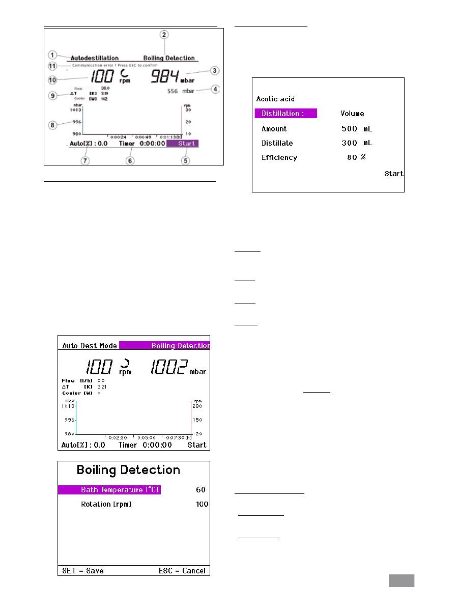
"Auto-distillation mode without boiling point recognition" menu
"Auto-distillation mode without boiling point recognition" display screen
1. Operating mode display
2. Control field for solvent
3. Vacuum display (actual value)
4. Vacuum display (target value)
5. Control field for „Start/ Stop“ distillation
6. Timer display
7. Distillation progress indicator
(% of required quantity of distillate)
8. Vacuum-rotation-time graph
9. Display of flow rate, differential temperature, and condenser heat
rejection rate.
10. Rotary speed display (target value) and speed measurement unit
11. Error message in case of fault, otherwise status indicator
Changing the selected solvent
Turn the Rotating/ Pressing knob to the right/left to select the control
field "Solvent".
Press the Rotating/ Pressing knob to display a list of the various solvents
available.
Turn the Rotating/ Pressing knob to the right/left to select a "Solvent".
Press the SET key.
The solvent selected will be used for the subsequent distillation.
Note: The display shows the parameters for each of the solvents. The
parameters can only be changed for the user-definable solvents User-
Solvent1 ... UserSolvent5. Please refer to the next section for instructions
on how to do this.
User defined solvents
Select one of the options NewSolvent1 ... NewSolvent5 from the "Sol-
vents" screen.
Select one of these solvents and press the Rotating/ Pressing knob.
All the parameters displayed for the solvent can now be modified.
Turn the Rotating/ Pressing knob to the right/left to select the para-
meter to be changed.
Press the Rotating/ Pressing knob.
Turn the Rotating/ Pressing knob to the right/left to change the selec-
ted parameter.
Press the Rotating/ Pressing knob.
Press SET to save all values.
This action selects NewSolvent1 as the current solvent.
Note: It is not possible to return to the selection list.
60
Starting automatic distillation
Press the Rotating/ Pressing knob with the “Start” or “Continue” field
selected. If the “100% distillation” or “Drying” options are active, then
the distillation will start immediately, provided that the necessary condi-
tions are fulfilled.
When the “Volume” distillation method is used, a further screen with
additional distillation parameters will be displayed.
Turn the Rotating/ Pressing knob to the right/left to select a menu
option.
Press the Rotating/ Pressing knob.
Turn the Rotating/ Pressing knob to change the value (the magnitude
of the change is dependent on the speed at which the knob is turned)
Press the Rotating/ Pressing knob again to complete the process.
Distillation
This field indicates the distillation method selected in Settings/Distillation
and cannot be changed.
Amount
Enter the amount, which the flask contains.
Distillate
Enter the amount, which you want to distill off.
Efficiency
Balancing requires a precise thermal efficiency to be entered.
The efficiency is dependent on a combination of factors that affect the
distillation process, so it must initially be estimated. The first time a di-
stillation process is carried out should therefore be used for calibration.
Following completion of the distillation process, determine the quantity
of distillate produced and calculate the actual heat rejection rate accor-
ding to the following formula:
η
th
. m
(calc)
η
P
=
m
(gem)
η
P
Actual efficiency
η
th
Estimated efficiency
m
(gem)
Measured quantity of distillate
m
(calc)
Specified (calculated) distillate quantity
For subsequent distillations, the actual calculated efficiency should be
entered; this will ensure that subsequent automatic distillations under
the same distillation and ambient conditions are performed with suffici-
ent precision.
End of automatic distillation
Automatic distillation will stop when the following conditions are met:
- Volume controlled
The specified quantity of distillate has been reached.
- 100% Distillation
The measured cooling water temperature has fallen below a target va-
lue, indicating that the solvent is fully evaporated.
The distillation can also be stopped manually:
Press the Rotating/ Pressing knob with the “Stop” display field selected.
"Auto-distillation mode with boiling point recognition" menu
"Auto-distillation mode with boiling point recognition" display screen
1. Operating mode display
2. Control field for solvent
3. Vacuum display (actual value)
4. Vacuum display (target value)
5. Control field for „Start/ Stop“ distillation
6. Timer display
7. Distillation progress indicator
(% of required quantity of distillate)
8. Vacuum-rotation-time graph
9. Display of flow rate, differential temperature, and condenser heat
rejection rate
10. Rotary speed display (target value) and speed measurement unit
11. Error message in case of fault, otherwise status indicator
Note: volume distillation is not possible as the solvent must be known
in this mode.
This mode allows selection of the bath temperature and speed of rota-
tion via the "Boiling point recognition" control field instead of selection
of the solvent.
