ASRock 990fx extreme9 – page 2
Manual for ASRock 990fx extreme9
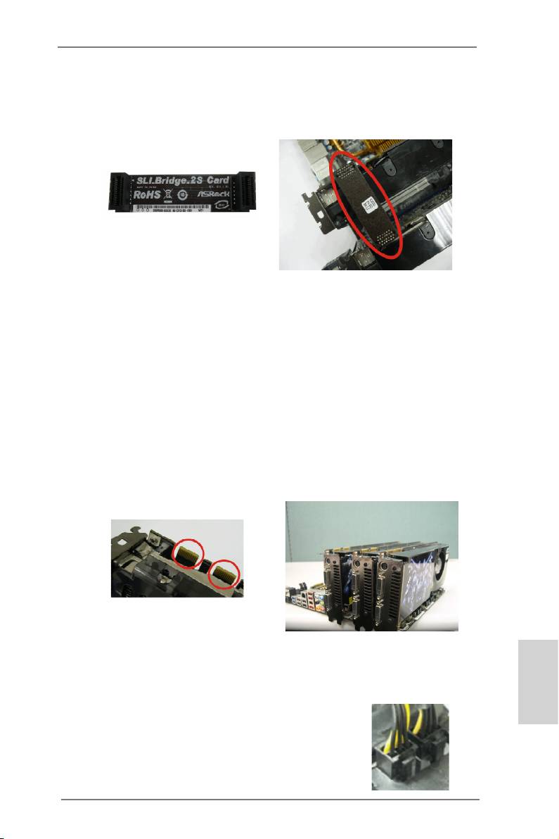
Step3. Align and insert the ASRock SLI_Bridge_2S Card to the goldngers on
each graphics card. Make sure the ASRock SLI_Bridge_2S Card is rmly
in place.
ASRock SLI_Bridge_2S Card
Step4. Connect a VGA cable or a DVI cable to the monitor connector or the DVI
connector of the graphics card that is inserted to PCIE1 slot.
TM
2.5.1.2 Installing Three SLI
-Ready Graphics Cards
TM
®
Step 1. Install the identical 3-Way SLI
-ready graphics cards that are NVIDIA
certied because different types of graphics cards will not work together
properly. (Even the GPU chips version shall be the same.) Each graph-
ics card should have two goldngers for ASRock 3-Way SLI-2S1S Bridge
Card connector. Insert one graphics card into PCIE1 slot, another graphics
card to PCIE4 slot, and the other graphics card to PCIE5 slot. Make sure
that the cards are properly seated on the slots.
Two Goldngers
Step2. Connect the auxiliary power source to the PCI Express graphics card.
Please make sure that both power connectors on the PCI Express graph-
ics card are connected. Repeat this step on the three graphics cards.
English
21
ASRock 990FX Extreme9 Motherboard
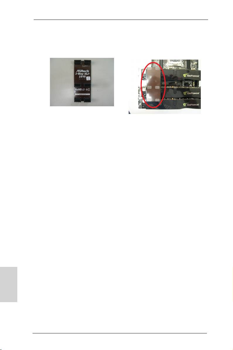
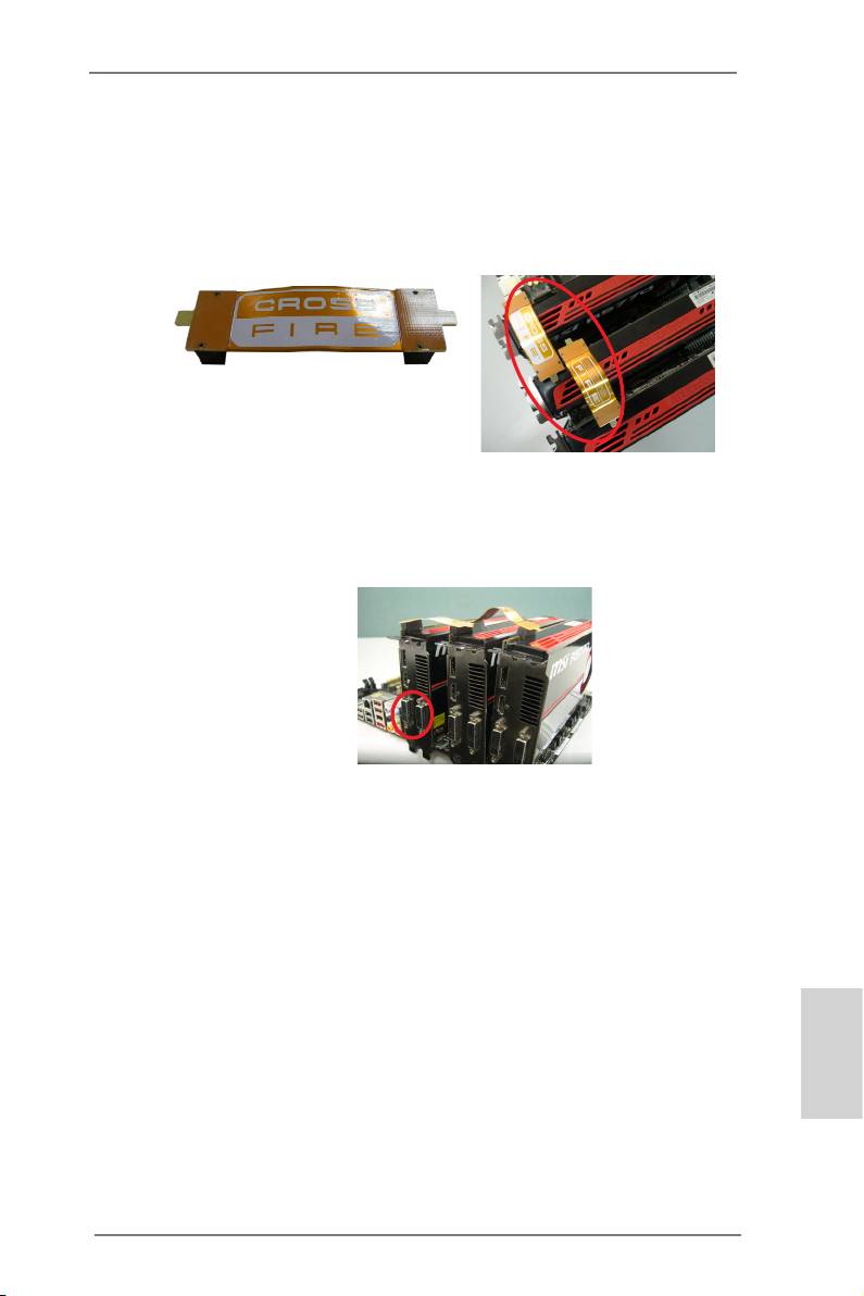
Step3. Align and insert ASRock 3-Way SLI-2S1S Bridge Card to the goldngers
on each graphics card. Make sure ASRock 3-Way SLI-2S1S Bridge Card
is rmly in place.
ASRock 3-Way SLI-2S1S Bridge Card
Step4. Connect a VGA cable or a DVI cable to the monitor connector or the DVI
connector of the graphics card that is inserted to PCIE1 slot.
Please refer to the “User Manual“ in our support CD for drivers installation and
setup procedures.
TM
®
* SLI
appearing here is a registered trademark of NVIDIA
Technologies Inc., and is used
only for identication or explanation and to the owners’ benet, without intent to infringe.
English
22
ASRock 990FX Extreme9 Motherboard
TM
TM
TM
2.6 CrossFireX
, 3-Way CrossFireX
and Quad CrossFireX
Operation Guide
TM
TM
This motherboard supports CrossFireX
, 3-way CrossFireX
and Quad
TM
TM
CrossFireX
feature. CrossFireX
technology offers the most advantageous
means available of combining multiple high performance Graphics Processing
Units (GPU) in a single PC. Combining a range of different operating modes with
TM
intelligent software design and an innovative interconnect mechanism, CrossFireX
enables the highest possible level of performance and image quality in any 3D
TM
®
application. Currently CrossFireX
feature is supported with Windows
XP with
TM
TM
TM
Service Pack 2 / Vista
/ 7 / 8 OS. 3-way CrossFireX
and Quad CrossFireX
®
TM
feature are supported with Windows
Vista
/ 7 / 8 OS only. Please check AMD
TM
website for AMD CrossFireX
driver updates.
1. If a customer incorrectly configures their system they will not see the
TM
TM
performance benets of CrossFireX
. All three CrossFireX
components, a
TM
TM
CrossFireX
Ready graphics card, a CrossFireX
Ready motherboard and a
TM
CrossFireX
Edition co-processor graphics card, must be installed correctly
TM
to benet from the CrossFireX
multi-GPU platform.
TM
2. If you pair a 12-pipe CrossFireX
Edition card with a 16-pipe card, both
TM
cards will operate as 12-pipe cards while in CrossFireX
mode.
2.6.1 Graphics Card Setup
TM
2.6.1.1 Installing Two CrossFireX
-Ready Graphics Cards
TM
Different CrossFireX
cards may require different methods to enable CrossFi-
TM
reX
feature. Please refer to AMD graphics card manuals for detailed installation
guide.
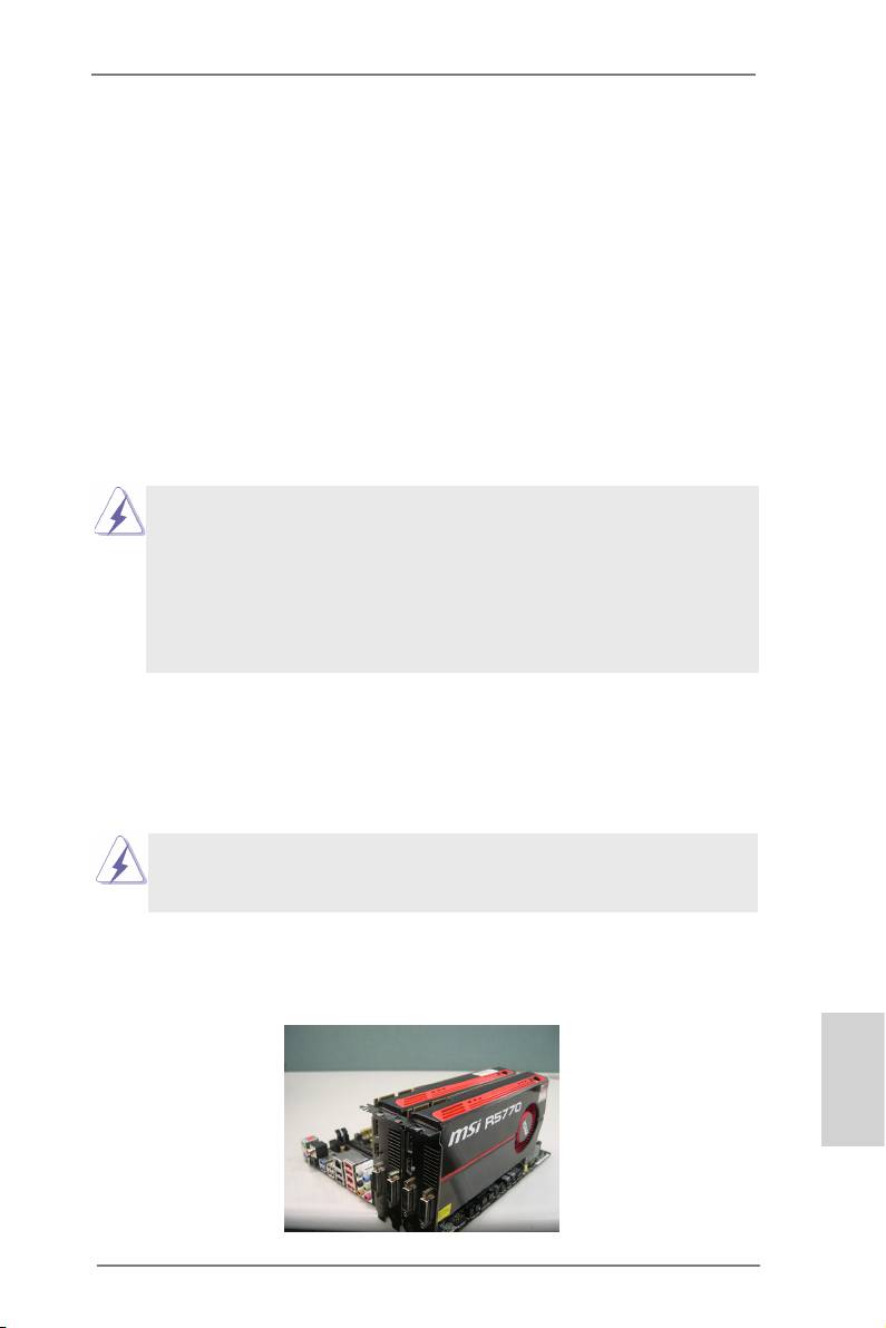
Step 1. Insert one Radeon graphics card into PCIE1 slot and the other Radeon
graphics card to PCIE4 slot. Make sure that the cards are properly seated
on the slots.
English
23
ASRock 990FX Extreme9 Motherboard
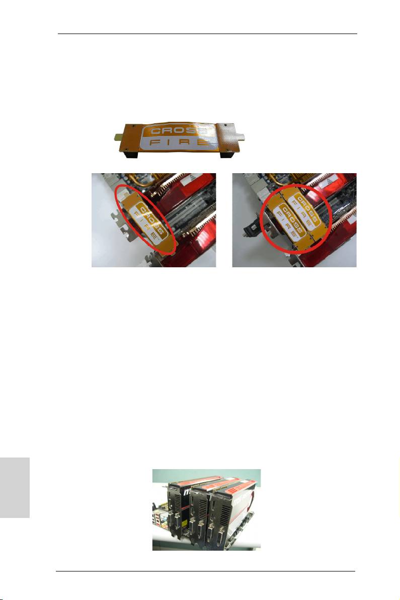
Step 2. Connect two Radeon graphics cards by installing CrossFire Bridge on
CrossFire Bridge Interconnects on the top of Radeon graphics cards.
(CrossFire Bridge is provided with the graphics card you purchase, not
bundled with this motherboard. Please refer to your graphics card vendor
for details.)
CrossFire Bridge
or
Step 3. Connect the DVI monitor cable to the DVI connector on the Radeon graph-
ics card on PCIE1 slot. (You may use the DVI to D-Sub adapter to convert
the DVI connector to D-Sub interface, and then connect the D-Sub monitor
cable to the DVI to D-Sub adapter.)
TM
2.6.1.2 Installing Three CrossFireX
-Ready Graphics Cards
TM
Step 1. Install the identical 3-Way CrossFireX
-ready graphics cards that are
AMD certied because different types of graphics cards will not work to-
gether properly. (Even the GPU chips version shall be the same.) Insert
one graphics card into PCIE1 slot, another graphics card to PCIE4 slot,
and the other graphics card to PCIE5 slot. Make sure that the cards are
properly seated on the slots.
English
24
ASRock 990FX Extreme9 Motherboard
TM
Step 2. Use one CrossFire
Bridge to connect Radeon graphics cards on PCIE1
TM
and PCIE4 slots, and use the other CrossFire
Bridge to connect Radeon
TM
graphics cards on PCIE4 and PCIE5 slots. (CrossFire
Bridge is provided
with the graphics card you purchase, not bundled with this motherboard.
Please refer to your graphics card vendor for details.)
TM
CrossFire
Bridge
Step 3. Connect the DVI monitor cable to the DVI connector on the Radeon graph-
ics card on PCIE1 slot. (You may use the DVI to D-Sub adapter to convert
the DVI connector to D-Sub interface, and then connect the D-Sub monitor
cable to the DVI to D-Sub adapter.)
Please refer to the “User Manual“ in our support CD for drivers installation and
setup procedures.
TM
* CrossFireX
appearing here is a registered trademark of AMD Technologies Inc., and is
used only for identication or explanation and to the owners’ benet, without intent to infringe.
TM
* For further information of AMD CrossFireX
technology, please check AMD website for
updates and details.
English
25
ASRock 990FX Extreme9 Motherboard
2.7 Jumpers Setup
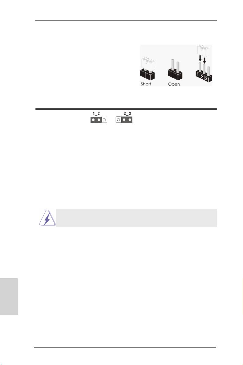
The illustration shows how jumpers are
setup. When the jumper cap is placed on
pins, the jumper is “Short”. If no jumper cap
is placed on pins, the jumper is “Open”. The
illustration shows a 3-pin jumper whose
pin1 and pin2 are “Short” when jumper cap
is placed on these 2 pins.
Jumper Setting
Clear CMOS Jumper
(CLRCMOS1)
(see p.2, No. 29)
Clear CMOSDefault
Note: CLRCMOS1 allows you to clear the data in CMOS. The data in CMOS in-
cludes system setup information such as system password, date, time, and
system setup parameters. To clear and reset the system parameters to de-
fault setup, please turn off the computer and unplug the power cord from the
power supply. After waiting for 15 seconds, use a jumper cap to short pin2
and pin3 on CLRCMOS1 for 5 seconds. However, please do not clear the
CMOS right after you update the BIOS. If you need to clear the CMOS when
you just nish updating the BIOS, you must boot up the system rst, and then
shut it down before you do the clear-CMOS action.
The Clear CMOS Switch has the same function as the Clear CMOS
jumper.
English
26
ASRock 990FX Extreme9 Motherboard

2.8 Onboard Headers and Connectors
Onboard headers and connectors are NOT jumpers. Do NOT place
jumper caps over these headers and connectors. Placing jumper caps
over the headers and connectors will cause permanent damage of the
motherboard!
Serial ATA3 Connectors These eight Serial ATA3
(SATA3_1_2: see p.2, No. 18)
(SATA3) connectors support
(SATA3_3_4: see p.2, No. 17)
SATA data cables for internal
(SATA3_5_6: see p.2, No. 16)
storage devices. The current
(SATA3_A1_A2: see p.2, No. 15)
SATA3 interface allows up to
6.0 Gb/s data transfer rate.
SATA3_1 SATA3_3 SATA3_5 SATA3_A1
SATA3_2 SATA3_4 SATA3_6 SATA3_A2
Serial ATA (SATA) Either end of the SATA data
Data Cable cable can be connected to the
(Optional)
SATA3 hard disk or the SATA3
connector on this motherboard.
Serial ATA (SATA) Please connect the black end
Power Cable of SATA power cable to the
(Optional)
power connector on each drive.
connect to the SATA
Then connect the white end of
HDD power connector
SATA power cable to the power
connect to the
power supply
connector of the power supply.
USB 2.0 Headers Besides four default USB 2.0
(9-pin USB4_5)
ports on the I/O panel, there
(see p.2 No. 26)
are two USB 2.0 headers on
English
this motherboard. Each USB 2.0
header can support two USB
2.0 ports.
27
ASRock 990FX Extreme9 Motherboard

(9-pin USB6_7)
(see p.2 No. 25)
USB 3.0 Headers Besides four default USB 3.0
(19-pin USB3_4_5)
ports on the I/O panel, there are
(see p.2 No. 12)
two USB 3.0 headers on this
motherboard. Each USB 3.0
header can support two USB
3.0 ports.
(19-pin USB3_6_7)
(see p.2 No. 11)
Infrared Module Header This header supports an
(5-pin IR1)
optional wireless transmitting
(see p.2 No. 32)
and receiving infrared module.
Front Panel Audio Header This is an interface for the front
GND
P RESENCE#
(9-pin HD_AUDIO1)
panel audio cable that allows
M IC_RET
OUT_RET
(see p.2 No. 34)
convenient connection and
control of audio devices.
1
O UT2_L
J _SENSE
O UT2_R
English
M IC2_R
M IC2_L
1. High Denition Audio supports Jack Sensing, but the panel wire on
the chassis must support HDA to function correctly. Please follow the
instruction in our manual and chassis manual to install your system.
2. If you use AC’97 audio panel, please install it to the front panel audio
header as below:
A. Connect Mic_IN (MIC) to MIC2_L.
28
ASRock 990FX Extreme9 Motherboard
B. Connect Audio_R (RIN) to OUT2_R and Audio_L (LIN) to OUT2_L.
C. Connect Ground (GND) to Ground (GND).
D. MIC_RET and OUT_RET are for HD audio panel only. You don’t
need to connect them for AC’97 audio panel.
E. To activate the front mic.
®
For Windows
XP / XP 64-bit OS:
Select “Mixer”. Select “Recorder”. Then click “FrontMic”.
®
TM
TM
For Windows
8 / 8 64-bit / 7 / 7 64-bit / Vista
/ Vista
64-bit OS:
Go to the “FrontMic” Tab in the Realtek Control panel. Adjust
“Recording Volume”.
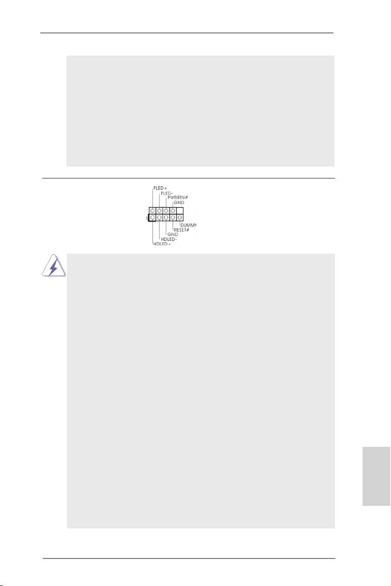
System Panel Header This header accommodates
(9-pin PANEL1)
several system front panel
(see p.2 No. 28)
functions.
Connect the power switch, reset switch and system status indicator
on the chassis to this header according to the pin assignments below.
Note the positive and negative pins before connecting the cables.
PWRBTN (Power Switch):
Connect to the power switch on the chassis front panel. You may con-
gure the way to turn off your system using the power switch.
RESET (Reset Switch):
Connect to the reset switch on the chassis front panel. Press the reset
switch to restart the computer if the computer freezes and fails to per-
form a normal restart.
PLED (System Power LED):
Connect to the power status indicator on the chassis front panel. The
LED is on when the system is operating. The LED keeps blinking
when the sys-tem is in S1 sleep state. The LED is off when the system
is in S3/S4 sleep state or powered off (S5).
HDLED (Hard Drive Activity LED):
Connect to the hard drive activity LED on the chassis front panel. The
LED is on when the hard drive is reading or writing data.
The front panel design may differ by chassis. A front panel module
mainly consists of power switch, reset switch, power LED, hard drive
English
activity LED, speaker and etc. When connecting your chassis front
panel module to this header, make sure the wire assignments and the
pin assign-ments are matched correctly.
29
ASRock 990FX Extreme9 Motherboard
Chassis Speaker Header Please connect the chassis
(4-pin SPEAKER 1)
speaker to this header.
(see p.2 No. 19)
Power LED Header Please connect the chassis
(3-pin PLED1)
power LED to this header to
(see p.2 No. 30)
indicate system power status.
The LED is on when the system
is operating. The LED keeps
blinking in S1 state. The LED is
off in S3/S4 state or S5 state
(power off).
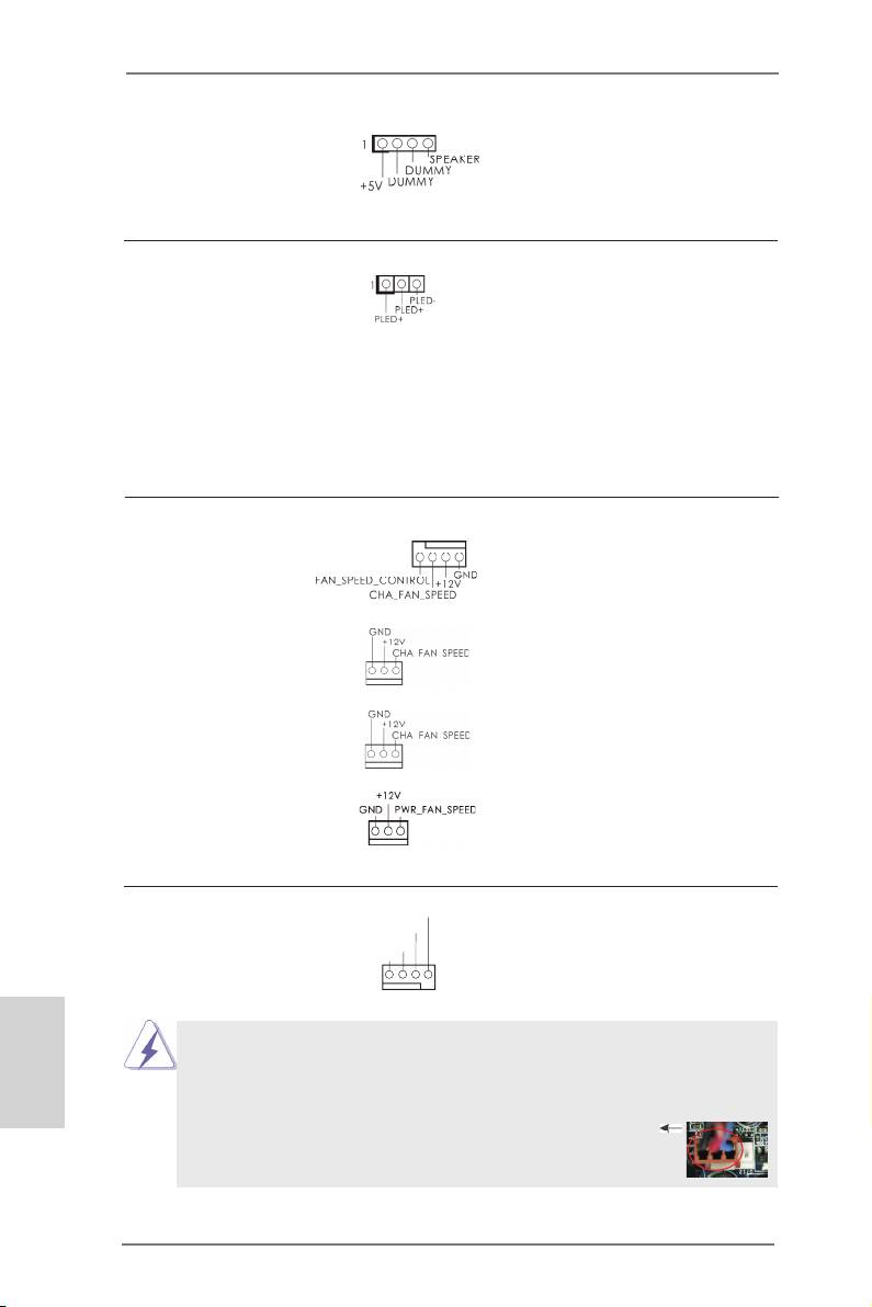
Chassis and Power Fan Connectors Please connect the fan cables
(4-pin CHA_FAN1)
to the fan connectors and
(see p.2 No. 20)
match the black wire to the
ground pin. CHA_FAN1/2/3 fan
speed can be controlled through
(3-pin CHA_FAN2)
UEFI or AXTU.
(see p.2 No. 6)
(3-pin CHA_FAN3)
(see p.2 No. 24)
(3-pin PWR_FAN1)
(see p.2 No. 9)
CPU Fan Connectors Please connect the CPU fan
FAN_S PEED_CONTROL
CPU_FAN_SPEED
(4-pin CPU_FAN1)
cable to the connector and
+ 12V
GND
(see p.2 No. 4)
match the black wire to the
ground pin.
1 2 3 4
English
Though this motherboard provides 4-Pin CPU fan (Quiet Fan) support, the 3-Pin
CPU fan still can work successfully even without the fan speed control function.
If you plan to connect the 3-Pin CPU fan to the CPU fan connector on this
motherboard, please connect it to Pin 1-3.
Pin 1-3 Connected
3-Pin Fan Installation
30
ASRock 990FX Extreme9 Motherboard
(3-pin CPU_FAN2)
GND
+ 12V
(see p.2 No. 5)
CPU_FAN_SPEED
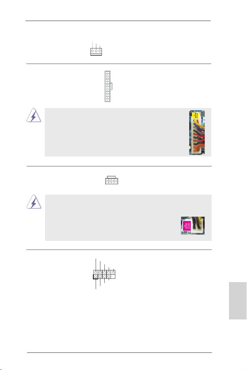
ATX Power Connector Please connect an ATX power
12
24
(24-pin ATXPWR1)
supply to this connector.
(see p.2 No. 10)
1
13
Though this motherboard provides 24-pin ATX power connector,
12
24
it can still work if you adopt a traditional 20-pin ATX power supply.
To use the 20-pin ATX power supply, please plug your
power supply along with Pin 1 and Pin 13.
20-Pin ATX Power Supply Installation
1
13
ATX 12V Power Connector Please connect an ATX 12V
8 5
(8-pin ATX12V1)
power supply to this connector.
(see p.2 No. 1)
4 1
Though this motherboard provides 8-pin ATX 12V power connector, it can still work
if you adopt a traditional 4-pin ATX 12V power supply. To use the 4-pin ATX power
supply, please plug your power supply along with Pin 1 and Pin 5.
8 5
4-Pin ATX 12V Power Supply Installation
4 1
IEEE 1394 Header Besides one default IEEE 1394
RXTPAM_0
GND
(9-pin FRONT_1394)
port on the I/O panel, there is
R XTPBM_0
+ 12V
GND
(see p.2 No. 33)
one IEEE 1394 header
1
(FRONT_1394) on this
+ 12V
R XTPBP_0
motherboard. This IEEE 1394
GND
RXTPAP_0
header can support one IEEE
1394 port.
English
31
ASRock 990FX Extreme9 Motherboard
Serial port Header This COM1 header supports a
(9-pin COM1)
serial port module.
(see p.2 No. 31)
Consumer Infrared Module Header This header can be used to
(4-pin CIR1)
connect the remote
(see p.2 No. 27)
controller receiver.
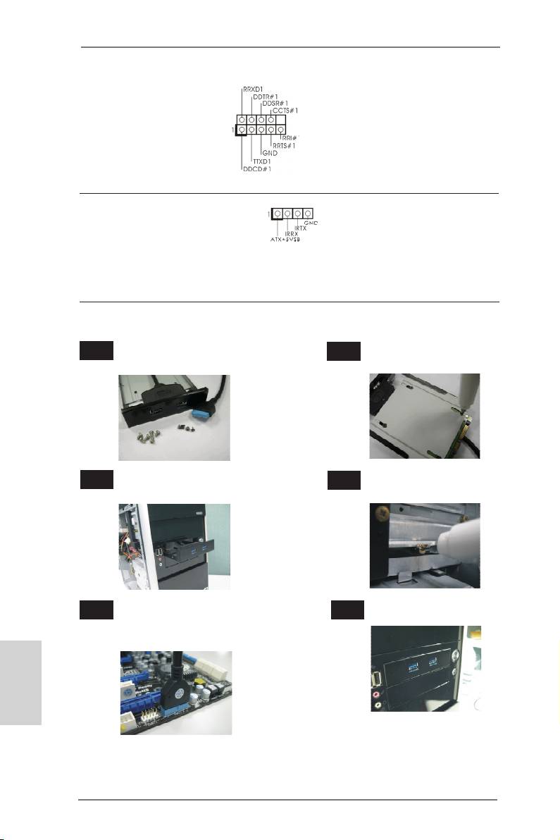
The Installation Guide of Front USB 3.0 Panel
Step 1
Prepare the bundled Front USB 3.0 Panel, four
Step 2
Screw the 2.5” HDD/SSD to the Front
HDD screws, and six chassis screws.
USB 3.0 Panel with four HDD screws.
Step 3
Intall the Front USB 3.0 Panel into the 2.5”
Step 4
Screw the Front USB 3.0 Panel to the
drive bay of the chassis.
drive bay with six chassis screws.
Step 5
Plug the Front USB 3.0 cable into the USB
Step 6
The Front USB 3.0 Panel is ready to use.
3.0 header (USB3_4_5 or USB3_6_7) on the
motherboard.
English
32
ASRock 990FX Extreme9 Motherboard
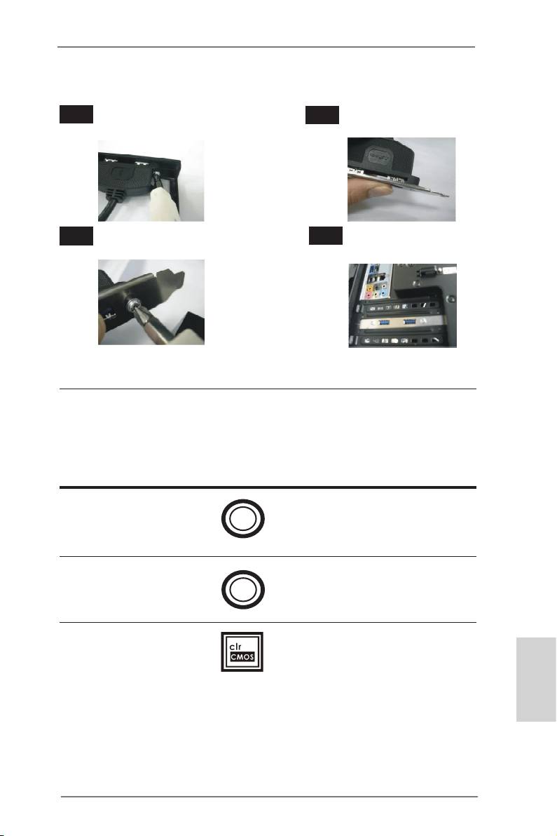
The Installation Guide of Rear USB 3.0 Bracket
Step 1
Unscrew the two screws from the Front USB 3.0
Step 2
Put the USB 3.0 cable and the rear
Panel.
USB 3.0 bracket together.
Step 3
Screw the two screws into the rear USB 3.0
Step 4
Put the rear USB 3.0 bracket into the
bracket.
chassis.
2.9 Smart Switches
The motherboard has three smart switches: power switch, reset switch and clear
CMOS switch, allowing users to quickly turn on/off or reset the sytem clear the
CMOS values.
Power Switch Power Switch is a smart switch,
(PWRBTN)
allowing users to quickly turn
Power
(see p.2 No. 21)
on/off the system.
Reset Switch Reset Switch is a smart switch,
(RSTBTN)
allowing users to quickly reset
Reset
(see p.2 No. 22)
the system.
Clear CMOS Switch Clear CMOS Switch is a smart
(CLRCBTN)
switch, allowing users to quickly
(see p.3 No. 18)
clear the CMOS values.
English
33
ASRock 990FX Extreme9 Motherboard

2.10 Dr. Debug
Dr. Debug is used to provide code information, which makes troubleshooting even
easier. Please see the diagrams below for reading the Dr. Debug codes.
Status Code Description
00 Please check if CPU is installed correctly and then clear CMOS.
0d Problem related to memory, VGA card and other devices.
Please clear CMOS, re-install memory and VGA card, and remove other
USB, PCI devices.
01 - 54 Problem related to memory. Please re-install CPU and memory then clear
(except 0d), CMOS.
5A- 60 If the problem still exists, please install only one memory module or try using
other memory modules.
55 Memory could not be detected. Please re-install memory and CPU.
If the problem still exists, please install only one memory module or try using
other memory modules.
61 - 91 Chipset initialization error. Please press reset or clear CMOS.
92 - 99 Problem related to PCI-E devices. Please re-install PCI-E devices or try
installing them in other slots.
If the problem still exists, please remove all PCI-E devices or try using
another VGA card.
A0 - A7 Problem related to IDE or SATA devices. Please re-install IDE and SATA
devices.
If the problem still exists, please clear CMOS and try removing all SATA
devices.
b0 Problem related to memory. Please re-install CPU and memory.
If the problem still exists, please install only one memory module or try using
other memory modules.
b4 Problem related to USB devices. Please try removing all USB devices.
b7 Problem related to memory. Please re-install CPU and memory then clear
CMOS.
If the problem still exists, please install only one memory module or try using
other memory modules.
d6 VGA could not be recognized. Please clear CMOS and try re-installing the
VGA card.
If the problem still exists, please try installing the VGA card in other slots or
using other VGA cards.
d7 Keyboard and mouse could not be recognized. Please try re-installing
English
keyboard and mouse.
d8 Invalid Password.
FF Please check if CPU is installed correctly and then clear CMOS.
34
ASRock 990FX Extreme9 Motherboard

2.11 Driver Installation Guide
To install the drivers to your system, please insert the support CD to your optical
drive rst. Then, the drivers compatible to your system can be auto-detected and
listed on the support CD driver page. Please follow the order from up to bottom side
to install those required drivers. Therefore, the drivers you install can work properly.
®
TM
2.12 Installing Windows
8 / 8 64-bit / 7 / 7 64-bit / Vista
/
TM
Vista
64-bit / XP / XP 64-bit With RAID Functions
®
TM
TM
If you want to install Windows
8 / 8 64-bit / 7 / 7 64-bit / Vista
/ Vista
64-bit / XP
/ XP 64-bit on your SATA3 HDDs with RAID functions, please refer to the document
at the following path in the Support CD for detailed procedures:
..\ RAID Installation Guide
®
TM
2.13 Installing Windows
8 / 8 64-bit / 7 / 7 64-bit / Vista
/
TM
Vista
64-bit / XP / XP 64-bit Without RAID Functions
®
TM
TM
If you want to install Windows
8 / 8 64-bit / 7 / 7 64-bit / Vista
/ Vista
64-bit / XP
/ XP 64-bit OS on your SATA3 HDDs without RAID functions, please follow below
procedures according to the OS you install.
®
2.13.1 Installing Windows
XP / XP 64-bit Without RAID
Functions
®
If you want to install Windows
XP / XP 64-bit on your SATA3 HDDs without RAID
functions, please follow below steps.
Using SATA3 HDDs without NCQ and Hot Plug functions (IDE mode)
STEP 1: Set up UEFI.
A. Enter UEFI SETUP UTILITY Advanced screen Storage Conguration.
B. Set the “SATA Mode” option to [IDE]. (For SATA3_1 to SATA3_6 ports.)
Set the option “ASMedia SATA3 Mode” to [IDE]. (For SATA3_A1 and SATA3_A2
English
ports.)
®
STEP 2: Install Windows
XP / XP 64-bit OS on your system.
35
ASRock 990FX Extreme9 Motherboard

®
TM
2.13.2 Installing Windows
8 / 8 64-bit / 7 / 7 64-bit / Vista
/
TM
Vista
64-bit Without RAID Functions
®
TM
TM
If you want to install Windows
8 / 8 64-bit / 7 / 7 64-bit / Vista
/ Vista
64-bit on
your SATA3 HDDs without RAID functions, please follow below steps.
Using SATA3 HDDs without NCQ and Hot Plug functions (IDE mode)
STEP 1: Set up UEFI.
A. Enter UEFI SETUP UTILITY Advanced screen Storage Conguration.
B. Set the “SATA Mode” option to [IDE]. (For SATA3_1 to SATA3_6 ports.)
Set the option “ASMedia SATA3 Mode” to [IDE]. (For SATA3_A1 and SATA3_A2
ports.)
®
TM
TM
STEP 2: Install Windows
8 / 8 64-bit / 7 / 7 64-bit / Vista
/ Vista
64-bit OS on
your system.
Using SATA3 HDDs with NCQ and Hot Plug functions (AHCI mode)
STEP 1: Set up UEFI.
A. Enter UEFI SETUP UTILITY Advanced screen Storage Conguration.
B. Set the “SATA Mode” option to [AHCI]. (For SATA3_1 to SATA3_6 ports.)
Set the option “ASMedia SATA3 Mode” to [AHCI]. (For SATA3_A1 and SATA3_A2
ports.)
®
TM
TM
STEP 2: Install Windows
8 / 8 64-bit / 7 / 7 64-bit / Vista
/ Vista
64-bit OS on
your system.
English
36
ASRock 990FX Extreme9 Motherboard

3. BIOS Information
The Flash Memory on the motherboard stores BIOS Setup Utility. When you start up
the computer, please press <F2> or <Del> during the Power-On-Self-Test (POST)
to enter BIOS Setup utility; otherwise, POST continues with its test routines. If you
wish to enter BIOS Setup after POST, please restart the system by pressing <Ctl>
+ <Alt> + <Delete>, or pressing the reset button on the system chassis. The BIOS
Setup program is designed to be user-friendly. It is a menu-driven program, which
allows you to scroll through its various sub-menus and to select among the prede-
termined choices. For the detailed information about BIOS Setup, please refer to the
User Manual (PDF le) contained in the Support CD.
4. Software Support CD information
®
®
This motherboard supports various Microsoft
Windows
operating systems: 8 / 8
TM
TM
64-bit / 7 / 7 64-bit / Vista
/ Vista
64-bit / XP / XP 64-bit. The Support CD that
came with the motherboard contains necessary drivers and useful utilities that will
enhance motherboard features. To begin using the Support CD, insert the CD into
your CD-ROM drive. It will display the Main Menu automatically if “AUTORUN” is
enabled in your computer. If the Main Menu does not appear automatically, locate
and double-click on the le “ASRSetup.exe” from the BIN folder in the Support CD
to display the menus.
English
37
ASRock 990FX Extreme9 Motherboard

1. Einführung
Wir danken Ihnen für den Kauf des 990FX Extreme9 Motherboard, ein zuverlässig-
es Produkt, welches unter den ständigen, strengen Qualitätskontrollen von ASRock
gefertigt wurde. Es bietet Ihnen exzellente Leistung und robustes Design, gemäß
der Verpflichtung von ASRock zu Qualität und Halbarkeit. Diese Schnellinstalla-
tionsanleitung führt in das Motherboard und die schrittweise Installation ein. Details
über das Motherboard nden Sie in der Bedienungsanleitung auf der Support-CD.
Da sich Motherboard-Spezikationen und BIOS-Software verändern
können, kann der Inhalt dieses Handbuches ebenfalls jederzeit geändert
werden. Für den Fall, dass sich Änderungen an diesem Handbuch
ergeben, wird eine neue Version auf der ASRock-Website, ohne weitere
Ankündigung, verfügbar sein. Die neuesten Grakkarten und unterstützten
CPUs sind auch auf der ASRock-Website aufgelistet.
ASRock-Website: http://www.asrock.com
Wenn Sie technische Unterstützung zu Ihrem Motherboard oder spezische
Informationen zu Ihrem Modell benötigen, besuchen Sie bitte unsere
Webseite:
www.asrock.com/support/index.asp
1.1 Kartoninhalt
990FX Extreme9 Motherboard (ATX-Formfaktor)
990FX Extreme9 Schnellinstallationsanleitung
990FX Extreme9 Support-CD
Ein ASRock SLI_Bridge_2S-Karte
Ein ASRock 3-Wege-SLI-2S1S-Brücke-Karte
Sechs Serial ATA (SATA) -Datenkabel (optional)
Zwei Serial ATA (SATA) -Festplattenstromkabel (optional)
Ein I/O Shield
Ein Vordere USB 3.0-Blende mit 2,5-Zoll-HDD/SSD-Rack
Vier Festplatte Schrauben
Sechs Gehäuses Schrauben
Ein USB 3.0-Blech an der Rückwand
Deutsch
ASRock erinnert...
®
TM
Zur besseren Leistung unter Windows
8 / 8 64 Bit / 7 / 7 64 Bit / Vista
/
TM
Vista
64 Bit empfehlen wir, die Speicherkonguration im BIOS auf den
AHCI-Modus einzustellen. Hinweise zu den BIOS-Einstellungen nden
Sie in der Bedienungsanleitung auf der mitgelieferten CD.
38
ASRock 990FX Extreme9 Motherboard

1.2 Spezikationen
Plattform - ATX-Formfaktor
- Hochwertiges Gold-Kondensatordesign (100 % hochwertige
japanische Fertigung leitfähiger Polymerkondensatoren)
- Multilter-Kondensator (MFC) (Filtert unterschiedliche
Störgrößen mit drei verschiedenen Kondensatoren:
DIP-Festkondensator, POSCAP und MLCC)
CPU - Unterstützung von Socket AM3+-Prozessoren
- Unterstützung von Socket AM3-Prozessoren: AMD
TM
Phenom
II X6 / X4 / X3 / X2 (außer 920 / 940) / Athlon X4 /
X3 / X2 / Sempron-Prozessor
- Acht-Kern-CPU-bereit
- Unterstützt UCC (Unlock CPU Core)
- Digi Power-Design
- Erweitertes 12 + 2-Stromphasendesign
- Dual-Stack-MOSFET (DSM)
- Unterstützt CPU bis 140W
TM
- Unterstützt Cool ‘n’ Quiet
-Technologie von AMD
- FSB 2600 MHz (5.2 GT/s)
- Unterstützt Untied-Übertaktungstechnologie
- Unterstützt Hyper-Transport- 3.0 Technologie (HT 3.0)
Chipsatz - Northbridge: AMD 990FX
- Southbridge: AMD SB950
Speicher - Unterstützung von Dual-Kanal-Speichertechnologie
- 4 x Steckplätze für DDR3
- Unterstützt DDR3 2450(OC)/2100(OC)/1600/1333/1066
non-ECC, ungepufferter Speicher
- Max. Kapazität des Systemspeichers: 64GB
®
- Unterstützt Intel
Extreme Memory Prole (XMP)1.3/1.2
- Unterstützt AMD Memory Prole (AMP)
Erweiterungs- - 4 x PCI Express 2.0 x16-Steckplätze (PCIE1: x16-Modus;
steckplätze PCIE3: x4-Modus; PCIE4/PCIE5: Einzeln bei x16 (PCIE4) /
x8 (PCIE5) oder dual im x8/x8-Modus)
- 1 x PCI Express 2.0 x1-Steckplätze
- 1 x PCI -Steckplätze
TM
TM
TM
- Unterstützt AMD
Quad CrossFireX
, 3-Way CrossFireX
Deutsch
TM
und CrossFireX
®
TM
TM
TM
- NVIDIA
Quad SLI
, 3-Way SLI
und SLI
Audio - 7.1
CH HD Audio mit dem Inhalt Schutz
(Realtek ALC898 Audio Codec)
39
ASRock 990FX Extreme9 Motherboard

- Premium Blu-ray-Audio-Unterstützung
LAN - PCIE x1 Gigabit LAN 10/100/1000 Mb/s
®
- Intel
82583V
- Unterstützt Wake-On-LAN
- Unterstützt PXE
E/A-Anschlüsse I/O Panel
an der Rückseite - 1 x PS/2-Mausanschluss
- 1 x PS/2-Tastaturanschluss
- 1 x Koaxial-SPDIF-Ausgang
- 1 x optischer SPDIF-Ausgang
- 4 x Standard-USB 2.0-Anschlüsse
- 4 x Standard-USB 3.0-Anschlüsse
- 2 x eSATA3-Anschlüsse
- 1 x RJ-45 LAN Port mit LED (ACT/LINK LED und SPEED
LED)
- 1 x IEEE 1394 Port
- 1 x CMOS löschen-Schalter
- HD Audiobuchse: Lautsprecher seitlich / Lautsprecher
hinten / Mitte/Bass / Audioeingang/ Lautsprecher vorne /
Mikrofon
SATA3 - 6 x AMD SB950 SATA 3-Anschluss mit 6,0 Gb/s, unterstützt
RAID-(RAID 0, RAID 1, RAID 0+1, JBOD und RAID 5),
NCQ-, AHCI- und „Hot Plugging“-Funktionen
- 2 x ASMedia ASM1061 SATA 3-Anschluss mit 6,0 Gb/s,
unterstützt NCQ-, AHCI- und „Hot Plugging“-Funktionen
USB3.0 - 4 x USB 3.0-Ports an der Rückseite durch Etron EJ188H,
unterstützt USB 1.1/2.0/3.0 mit bis zu 5 Gb/s
- 2 x USB 3.0-Anschlüsse (unterstützt 4 USB 3.0-Ports) an
der Vorderseite durch Etron EJ188H, unterstützt USB
1.1/2.0/3.0 mit bis zu 5 Gb/s
Anschlüsse - 8 x SATA3 6,0 GB/s-Anschlüsse
- 1 x Infrarot-Modul-Header
- 1 x Consumer Infrarot-Modul-Header
- 1 x COM-Anschluss-Header
Deutsch
- 1 x IEEE 1394-Anschluss
- 1 x Betriebs-LED-Header
- 2 x CPUlüfter-Anschluss (1 x 4-pin, 1 x 3-pin)
- 3 x Gehäuselüfter-Anschluss (1 x 4-pin, 2 x 3-pin)
- 1 x Stromlüfter-Anschluss (3-pin)
- 24-pin ATX-Netz-Header
40
ASRock 990FX Extreme9 Motherboard


