Pfannenberg PYRA PY X-S-05 Series: instruction
Class: Safety, Home Security
Type:
Manual for Pfannenberg PYRA PY X-S-05 Series
085 501 949j
30320-004j
1
PY X-S-05 - Blitzleuchte
Betriebs- und Montageanleitung
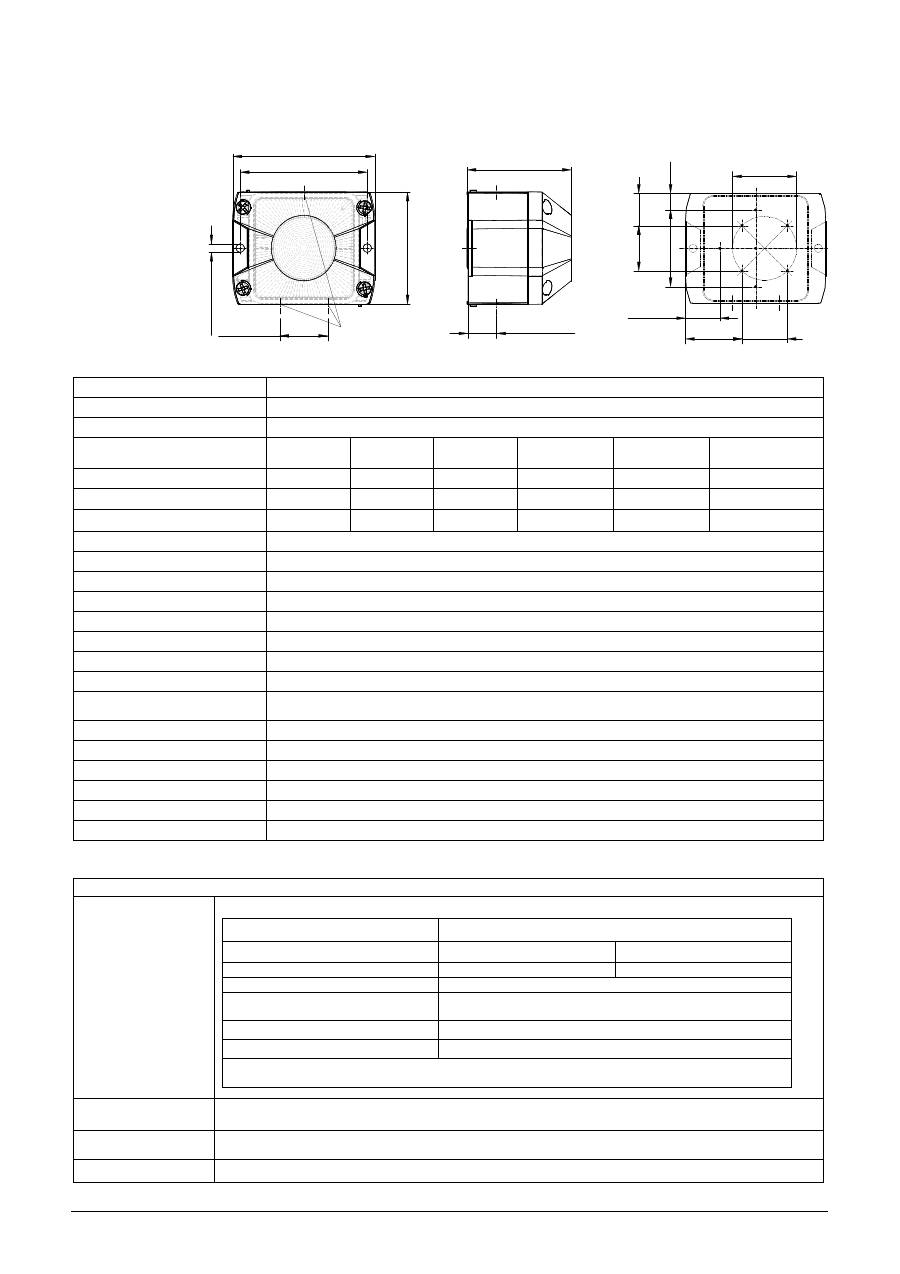
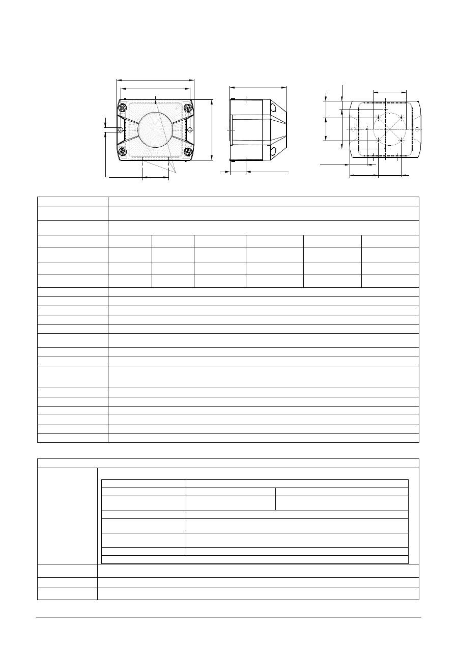
Maße
37 [1.46"]
M20-Ausbruch
vorbereitet
86
[
3,
38
5]
Ø
6.
3
[0
.2
5
]
98 [3.86]
109.6 [4.31]
80.6 [3.17]
22 [0.87"]
Technische Daten
Blitzenergie
5J
Effektive Nennlichtstärke
44 cd (klar)
Blitzfolgefrequenz
1Hz
Bemessungsspannung
12 V DC
24V DC
48V DC
24V AC
50/60 Hz
115 V AC
50/60 Hz
230V AC
50/60 Hz
Spannungsbereich
10 –15 V DC 18 – 30 V DC 40 – 57V DC
18 – 30V AC
95 - 127 V AC
195– 253 V AC
Stromaufnahme (max)
700 mA
360 mA
170 mA
800 mA
120 mA
90mA
Leistungsaufnahme
7,5 W
9,5 W
7,5 W
30 VA
14,5 VA
21,5 VA
Einschaltdauer
100%
Anschlussklemmen
0,14 - 2,5mm² feindrähtig / AWG24 - AWG 14 (stranded)
Schutzart
IP66 (EN60529) , Type 4 & 4x
Schutzklasse
II
Betriebstemperatur
-40°C…+55°C
Lagertemperatur
-40°C…+70°C
Max. rel. Luftfeuchte
90%
Kabeleinführung
4x M20 vorgeprägt
Dichtbereich der
Durchführungstülle
7 – 13 mm - Bei Verwendung von Kabeldurchmessern < 7 mm ist eine Kabelverschraubung mit
ausreichender Schutzart vorzusehen
Gehäusematerial
PC/ABS Blend
Haubenmaterial
PC
Einbaulage
beliebig
Optionen
-SSM, (siehe Seite 2)
Zubehör
Plombierstopfen (Art.-Nr. 28300000002)
Haubenfarben
klar, weiß, gelb, orange, rot, grün, blau
Zulassungen
Zulassungen
(gilt für gekennzeichnete Betriebsmittel)
Bauproduktrichtlinie
(89/106/EWG)
VdS 0786-CPD-21219
Optionen
–SSM (nur 24V DC)
Bemessungsspannung
24V DC
48V DC
Spannungsbereich gemäß EN54-23
18V – 30V
40 – 57V DC
Haubenfarbe
rot, klar
Signalisierungsbereich
EN 54-23 Kategorie O:
siehe Dokument 30320-005-1
Umweltschutzklasse
Typ B
Einbaulage
siehe Dokument 30320-005-1
Die Prüfung erfolgte unter Verwendung des mitgelieferten Membrannippels und der äußeren
Befestigungsbohrungen.
VdS
G212186,
Daten siehe Bauproduktenrichtlinie (89/106/EWG)
GL
61062-13 HH
Umweltkategorie C, H, EMC1
UL, cUL
UEES, UEES7 (weiterführende Informationen siehe Seite 3)
Kartoninhalt:
1x Alarmgerät
1x Membrannippel M20
1x Betriebsanleitung
1x Widerstand (nur –SSM)
44.1 [1.74"]
35.4
[1.39"]
25
.3
[1
"]
13
[0
.5
1"
]
50 [1.97"]
26.8 [1.06"]
35
.4
[1
.3
9"
]
60
[2
.3
6"
]
Bohrbild im Inneren
des Gehäuses
085 501 949j
30320-004j
2
Inbetriebnahme
Sicherheitshinweise:
- Der elektrische Anschluss darf nur von hierfür autorisierten Personen in Übereinstimmung mit den derzeit gültigen
Vorschriften durchgeführt werden.
- Warnung vor gefährlicher hoher elektrischer Spannung.
- Vor dem Öffnen ist sicherzustellen, dass das Gerät nicht unter Spannung steht.
- Vor Inbetriebnahme ist die auf dem Typenschild angegebene Versorgungsspannung zu kontrollieren. Eine falsche
Betriebsspannung kann zur Schädigung bzw. zur Zerstörung des Betriebsmittels führen.
- Bei der Installation ist darauf zu achten, dass die Anschlussleitung gegen Zug und Verdrehen abgesichert ist.
Bitte beachten: Die Geräte sind nicht für einen ortsveränderlichen Einsatz bestimmt.
- WARNUNG: Bei Installation Verdrahtung entfernt von scharfen Kanten, Ecken und internen Komponenten.
- Die Funktion des Gerätes ist nur gewährleistet, wenn Ober- und Unterteil korrekt zusammengefügt sind.
- Um eine Beeinträchtigung des Sehvermögens zu verhindern, ist der dauernde, direkte Blick in die aktivierte Leuchte zu
vermeiden.
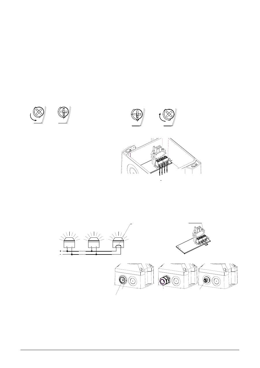
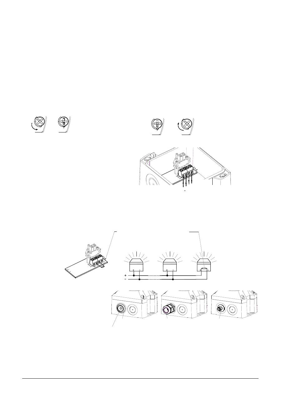
Öffnen des Gehäuses:
Verschließen des Gehäuses
3/8
1.
2.
3/8
1.
2.
Das Gerät wird in nicht verschlossenem Zustand ausgeliefert.
Plombierstopfen für die Gehäuseschrauben sind als Zubehör erhältlich.
Elektrischer Anschluss:
Option –SSM (Soft-Start-Modul) (nur 24V DC):
- Begrenzung der Einschaltstromspitze auf max. 2,1A
- Durchschalten der Betriebsspannung zum Betriebsmittel erst ab >7V
- Widerstand zur Leitungsüberwachung angeschlossen.
Betriebsspannungsbereich: 18V – 30V DC
Anschluss eines Widerstandes
zur Leitungsüberwachung:
Kabeldurchführungen
Zur Sicherstellung der angegebenen Schutzart sind
an den dafür vorgesehenen Durchbrüchen
Kabeldurchführungen mit einer Schutzart von IP 66
zu montieren. Der mitgelieferte Membrannippel
kann durch eine Kabelverschraubung oder durch
einen M12-Steckverbinder mit einem Flanschmaß
von M20 ersetzt werden.
Wartung, Service, Instandhaltung
Das Gerät erfordert keine besondere Wartung. Die äußere Reinigung sollte mit einer schwachen Seifenlösung ohne
Verwendung von Lösungsmittel erfolgen.
Die Blitzleuchte darf nur in unbeschädigtem Zustand innerhalb der spezifizierten Kenndaten betrieben werden. Umbauten,
Änderungen, fehlerhafter und unzulässiger Einsatz sowie die Nichtbeachtung der Hinweise dieser Betriebsanleitung
schließen eine Gewährleistung aus.
Ein Austausch von Komponenten darf nur mit Originalersatzteilen erfolgen. Reparaturen sind grundsätzlich im
Herstellerwerk auszuführen.
Durch Lösen der vier
Deckelschrauben lässt
sich das Oberteil
abnehmen
Verschließen des Gehäuses
durch Drehen der
Deckelschrauben in die
Endstellung bis zur
Verrastung.
Anschlussplatine
im Unterteil
X1
Betriebsspannungs-
anschluss
N
L
+
M12- Steckverbinder IP 66
(für Kleinspannungs-Geräte)
IP 66
Kabelverschraubung
(mitgeliefert)
Membrannippel IP 66
Nach Montage des Kabels
Reste der Membrane entfernen.
Nicht benötigte Widerstände entfernen.
X1
am Betriebsspannungsanschluss.
Widerstand für Leitungsüberwachung (1KOhm)
von mehreren Leuchten im letzten Gerät.
Position des Widerstandes bei Parallelschaltung
085 501 949j
30320-004j
3
PY X-S-05 – Beacon Operating and installation instruction
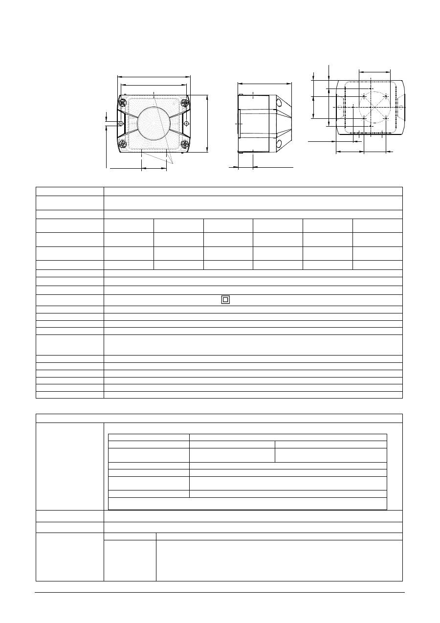
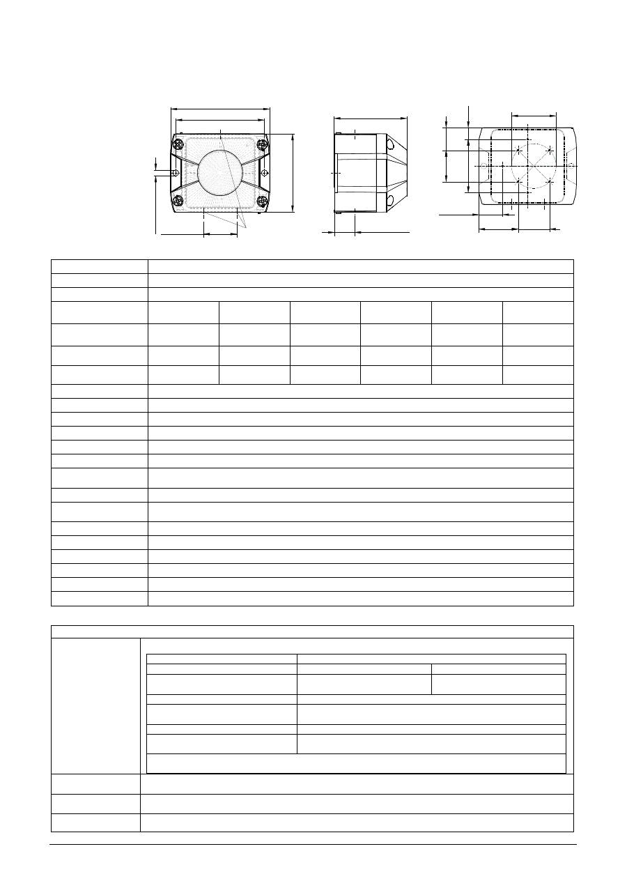
Dimensions
Ø
6.
3
[0
.2
5]
22 [0.87"]
80.6 [3.17]
109.6 [4.31]
98 [3.86]
86
[3
,3
85
]
prepared
M20 piercing
37 [1.46"]
Technical Data
Flash energy
5J
Rated effective luminous
intensity
44 cd (clear)
Flash frequency
1Hz
Rated voltage
12 V DC
24V DC
48V DC
24V AC
50/60 Hz
115 V AC, 50/60
Hz
230V AC
50/60 Hz
Operating voltage range
10 –15 V DC
18 – 30 V DC
40 – 57 V DC
18 – 30 V AC
95 - 127
V AC
195 – 253 V AC
Current consumption
(max)
700 mA
360 mA
170 mA
800 mA
120 mA
90mA
Power consumption
7,5 W
9,5 W
7,5 W
30 VA
14,5 VA
21,5 VA
Duty cycle
100%
Connection terminal
0,14 - 2,5mm² / AWG24 - AWG 14 (stranded)
Protection system
IP66 (EN60529), Type 4 & 4x
Protection class
II
Double insulated equipment
Operating temperature
-40°C…+55°C
Storage temperature
-40°C…+70°C
Max. rel. Humidity
90%
Cable entry
4x M20 (prepared)
Sealing range of
grommet
7 – 13 mm
With the use of cable diameters <7 mm, a cable screw joint
with sufficient ingress protection must be provided
Material of housing
PC/ABS Blend
Material of lens
PC
Installation position
arbitrary
Options
-SSM (see page 4)
Accessory
Sealing plug (Art-no. 28300000002)
Lens colours
clear, white, yellow, amber, red, green, blue
Approvals
Approvals
(valid for marked equipment)
Construction Product
Directive
(89/106/EWG)
VdS 0786-CPD-21219
Options
–SSM (24V DC only)
Rated voltage
24V DC
48V DC
Operating voltage range
acc. to EN54-23
18V – 30V
40 – 57V DC
Lens colours
red, clear
Signalling area
EN 54-23 Category O: see document 30320-005-1
Environmental
protection class
Type B
Installation position
see document 30303-005-1
The test was performed using the provided diaphragm nipples and the outer fixing holes.
VdS
G212186
, data see Construction Product Directive (89/106/EWG)
GL
61062-13 HH
Environmental Category C, H, EMC1
Rated Voltage
Visual Signal Appliance - General Signaling Equipment - UEES, UEES7
UL, cUL
115V AC
230V AC
24V AC
12V DC
24V DC
48V DC
Suitable for indoor and outdoor use.
Warning: Not to be used as a Visual Public Mode Alarm Notification Appliance.
According to CSA-C22.2 No. 205-M1983 clause 4.3.4 the connection is limited to max.
three leads.
PYRA Xenon beacons PY X-S-05 comply with the limits for a Class B digital device, pursuant to part 15 of the FCC Rules
Content of package:
1x Alarm device
1x Diaphragm nipple M20
1x Operating instruction
1x Resistor (only –SSM)
44.1 [1.74"]
35.4
[1.39"]
25
.3
[1
"]
13
[0
.5
1"
]
50 [1.97"]
26.8 [1.06"]
35
.4
[1
.3
9"
]
60
[2
.3
6"
]
Hole pattern in the
inside of housing
085 501 949j
30320-004j
4
Taking into operation
Safety notes:
- Installation must be carried out by an electrician in compliance with the latest codes and regulations.
- Danger: High voltage may be present.
- Prior to opening, it must be ensured that no voltage is applied to the device.
- Before electrical connection, the supply voltage on the type plate is to be checked. The wrong operating voltage can
lead to damages or to the destruction of the equipment.
- During installation it must be ensured that the connection cables are secured against tension and distortion.
Please observe: The devices are not designed for portable use.
- CAUTION: When making installation, route field wiring away from sharp projections, corners and internal
components.
- The function of the unit is only guaranteed if the upper and lower section is joined correctly.
- In order to prevent detriment to sight, continuously looking directly in the activated light is to be avoided.
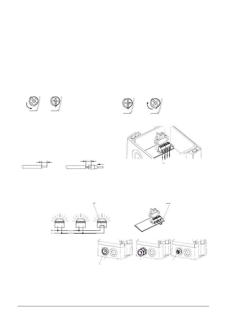
Opening the housing
Closing the housing
3/8
1.
2.
3/8
1.
2.
The unit is not closed when delivered.
Sealing plugs for the housing screws are available as accessories.
Electrical connection:
Connecting cables:
7 [0.28"]
7 [0.28"]
solid
stranded
Option –SSM (Soft-Start-Module) (24V DC only):
- Limiting of the switch-on current peak to max. 2.1A
- Connection of the operating voltage to the equipment starts at >7V
- Resistance for the line monitoring connected.
Operating voltage range: 18V – 30V DC
Connection of a resistor
for line monitoring:
Cable gland entries
To guarantee the specified protection type,
cable grommets with a protection type of IP 66
are to be installed at the openings provided for
this purpose. The supplied diaphragm nipple
can be replaced with a cable gland or with an
M12 plug connection with a flange
measurement of M20.
Maintenance, Service and Ordering Spare Parts
The device does not require any special maintenance. External cleaning should be done with a mild soap solution
without the use of solvents. The device may only be operated in the undamaged state within the specified rating.
Conversions, alterations, improper and inadmissible use as well as the non-observance of the notes in these
operating instructions shall render the warranty null and void.
Components may be replaced only by original spare parts. As a matter of principle, repairs are to be carried out in the
manufacturing works.
Circuit board for electrical
connection (located in the
base section):
By loosing the four cover
screws, the upper section
can be removed.
The housing is closed by
turning the cover screws to
the limit position until the
housing locks into place.
N
L
+
Connection for
Operating voltage
the remaining membrane break-out.
After pushing through the cable remove
Diaphragm nipple IP 66
(provided)
(for low voltage versions)
M12 plug connector IP 66
Cable gland IP 66
Position of resistor in last device when using several beacons in parallel
Resistor for line monitoring (1KOhm) at terminal for operating voltage
X1
Remove resistors that are not needed
085 501 949j
30320-004j
5
PY X-S-05 – Lampe à éclairs Instructions d’utilisation et de montage
Dimensions
Ø
6.
3
[0
.2
5]
80.6 [3.17]
22 [0.87"]
109.6 [4.31]
Encoche
préparée pour le M20
86
[3
,3
85
]
98 [3.86]
37 [1.46"]
Caractéristiques techniques
Energie lumineuse
5J
Nom. intensité
lumineuse effective
44 cd (clair)
Fréquence de répétition
du clignotement
1 Hz
Tension de service
12 V CC
24V CC
48V CC
24V CA 50/60 Hz 115 V CA, 50/60 Hz 230V CA 50/60 Hz
Plage de la tension de
service
10 –15 V CC 18 – 30 V CC
40 – 57V CC
18 – 30V CA
95 - 127 V CA
195 – 253 V CA
Courant nominal (max)
700 mA
360 mA
170 mA
800 mA
120 mA
90mA
Puissance
7,5 W
9,5 W
7,5 W
30 VA
14,5 VA
21,5 VA
Facteur de marche
100%
Bornes de connexion
0,14 - 2,5 mm² en fils de faible diamètre/ AWG24 - AWG 14 (stranded)
Type de protection
IP66 (EN60529), Type 4 & 4x
Classe de protection
II
Température de service
-40°C…+55°C
Température de
stockage
-40°C…+70°C
Humidité relative max.
90%
Entrée de câbles
4 x M20 avec empreinte préalable
Zone d’intensité du
profilé de protection
7 – 13 mm
En cas d’utilisation de câbles de diamètre < 7 mm, un raccord de câble équipé d’un type de protection suffisant
sera à prévoir
Matériau du boîtier
Mélange PC/ABS
Matériau du capot
PC
Position de montage
quelconque
Options
-SSM (voir page 6)
Accessoires
Bouchon de plombier (art. n° 28300000002)
Couleurs du capot
Clair, blanc, jaune, orange, rouge, vert, bleu
Admissions
Admissions
(valable pour les appareils signalés)
Directive sur les
produits de
construction
(89/106/CEE)
VdS 0786-CPD-21219
Options
–SSM (uniquement 24V DC)
Tension de service
24V CC
48V CC
Plage de tension de service
selon EN54-23
18V – 30V
40 – 57V
Couleur du capot
rouge, transparent
Plage de signalisation
EN 54-23 catégorie O:
Voir document 30320-005-1
Classe de protection
environnementale
Type B
Position de montage
voir document 30320-005-1
Le test a été effectué en utilisant le raccord fileté de membrane livré et les perçages extérieurs de fixation.
VdS
G212186,
pour les caractéristiques voir la Directive sur les Produits de construction (89/106/CEE)
GL
61062-13 HH
Catégorie environnementale C, H, EMC1
UL, cUL
UEES, UEES7 (plus d'informations voir page 3)
Contenu de l’emballage :
1 alarme
1 raccord fileté
à membrane M20
1 instruction d’utilisation
1 résistance
(seulement –SSM)
44.1 [1.74"]
35.4
[1.39"]
25
.3
[1
"]
13
[0
.5
1"
]
50 [1.97"]
26.8 [1.06"]
35
.4
[1
.3
9"
]
60
[2
.3
6"
]
Points de fixation à
l'intérieur du boîtier
085 501 949j
30320-004j
6
Mise en service
Consignes de sécurité:
- Le branchement électrique doit être effectué uniquement par des personnes autorisées conformément aux réglementations en
vigueur.
- Attention : Pendant le fonctionnement, hautes tensions générées.
- Avant d'ouvrir, il convient de s'assurer que l’appareil est hors tension.
- La tension d'alimentation indiquée sur la plaque signalétique doit être vérifiée avant la mise en service. Une tension de service
incorrecte peut entraîner un endommagement ou la destruction de l’appareil.
- Il convient de veiller, lors de l'installation, que les cordons d’alimentation ne sont pas soumis à des contraintes de traction ou
de torsion. Attention : les appareils ne sont pas destinés à une utilisation mobile.
- AVERTISSEMENT : lors de l’installation, maintenir les câblages éloignés des bords coupants, coins et composants internes.
- Le fonctionnement de l’appareil n’est garanti que si les parties supérieure et inférieure sont assemblées correctement.
- Pour éviter un risque d'endommagement de l'acuité visuelle, il convient d'éviter le contact visuel direct et permanent avec la
lampe.
Ouverture du boîtier
Fermeture du boîtier
3/8
1.
2.
3/8
1.
2.
L’appareil est livré en état non verrouillé.
Des bouchons de plombier sont disponibles en accessoires pour les vis du boîtier.
Raccordement à la tension de service:
Option SSM (Module Soft-Start) (uniquement 24 V CC) :
- Limitation de la pointe du courant à l’enclenchement à 2,1 A maxi.
- Transfert de la tension de service sur l’équipement à partir de > 7V
- Résistance à la direction des circuits intégrée
Plage de la tension de service : 18 V – 30 V DC
Résistance pour surveillance de ligne
Passages de câbles
Afin de garantir le type de protection
indiqué, des passages de câbles d’une
protection IP 66 doivent être montés au
niveau des perçages prévus à cet effet. Le
raccord fileté à membrane fourni peut être
remplacé par un passe-câble à vis ou par
un connecteur M12 avec une bride de
dimension M20.
Maintenance, SAV, entretien
L’appareil ne requiert aucune maintenance particulière. Le nettoyage extérieur doit être effectué avec une solution
légèrement savonneuse, sans solvants.
L’appareil doit être exploité uniquement en bon état de marche et dans le respect des caractéristiques indiquées. Toute
transformation, modification, utilisation incorrecte ou inadmissible ainsi que le non-respect des instructions de service
entraînent l'exclusion de la garantie.
Tous les composants doivent être remplacés uniquement par des pièces originales. Les réparations doivent en principe être
effectuées dans les ateliers du fabricant.
Platine de raccordement
dans la partie inférieure
La partie supérieure peut
être retirée en desserrant
les quatre vis du couvercle
Le boîtier se referme en
tournant les vis du couvercle
jusqu’en position finale pour
le verrouillage.
Raccordement à la
tension de service
N
L
+
Raccord fileté à membrane
IP 66 (fourni)
retirer le reste de la membrane
Après l'assemblage du câble
basse tension)
(pour les appareils
Connecteur M12 IP 66
Passe-câble à vis IP 66
au niveau du raccordement de la tension de service.
Résistance pour surveillance de ligne (1KOhm)
Position de la résistance en cas de montage en parallèle
Retirer les résistances, si elles ne sont pas nécessaires.
X1
085 501 949j
30320-004j
7
Проблесковая лампа PY X-S-05 Инструкция по монтажу и эксплуатации
Размеры
37 [1.46"]
M20-Ausbruch
vorbereitet
86
[
3,
38
5]
Ø
6.
3
[0
.2
5
]
98 [3.86]
109.6 [4.31]
80.6 [3.17]
22 [0.87"]
Технические данные
Энергия
вспышки
5
Дж
Сила
света
44
кд
(
прозрачная
)
Частота
вспышки
1Hz
Рабочее
напряжение
12
В
DC
24
В
DC
48
В
DC
24
В
AC
50/60
Гц
115
В
AC
50/60
Гц
230
В
AC
50/60
Гц
Диапазон
рабочего
напряжения
10 –15
В
DC
18 – 30
В
DC
40 – 57
В
DC
18 – 30
В
AC
95 - 127
В
AC
195 – 253
В
AC
Номинальный
ток
(
Макс
)
700
мА
360
мА
170
мА
800
мА
120
мА
90
мА
Мощность
7,5
вт
9,5
вт
7,5
вт
30 VA
14,5 VA
21,5 VA
Рабочий
цикл
100%
Соединения
0,14 - 2,5
мм
²,
с
тонким
проводом
/ AWG24 - AWG 14 (
многожильное
)
Тип
защиты
IP66 (EN60529), Type 4 & 4x
Класс
защиты
II
Рабочая
температура
-40°C…+55°C
Температура
хранения
-40°C…+70°C
Макс
.
отн
.
влажность
воздуха
90%
Кабельный
ввод
M20, 4
шт
,
предварительно
подготовлены
Допустимый
диаметр
кабеля
7 – 13
мм
;
при
использовании
кабеля
диаметром
менее
7
мм
должна
применяться
резьбовая
втулка
с
соответствующим
классом
защиты
Материал
корпуса
Поликарбонат
/
акрилонитрил
-
бутадиен
-
стирол
Материал
крышки
Поликарбонат
Монтажное
положение
Произвольное
Опции
-SSM (
см
.
стр
. 8)
Аксессуары
Пломбировочные
пробки
(
арт
. 28300000002)
Цвет
линзы
прозрачная
,
белый
,
жёлтый
,
оранжевый
,
красный
,
зелёный
,
синий
Допуски
Допуски
(
только
для
оборудования
с
маркировкой
)
Директива
Европейского
Союза
по
строительным
изделиям
(89/106/EWG)
VdS 0786-CPD-21219
Опции
–SSM (
для
24
В
DC)
Рабочее
напряжение
24V
пост
.
тока
48V
пост
.
тока
Диапазон
рабочего
напряжения
согласно
EN54-23
18 – 30
В
40 – 57
В
Цвет
линзы
красный
,
прозрачный
Область
использования
сигнализации
EN 54-23
категория
O:
см
.
документ
30320-005-1
Класс
защиты
окружающей
среды
Б
Монтажное
положение
см
.
документ
30320-005-1
Испытания
проводились
с
использованием
мембранного
ниппеля
(
в
комплекте
)
и
внешних
крепежных
отверстий
.
Союз
страховщиков
G212186
,
см
.
Директиву
ЕС
по
строительным
изделиям
(89/106/EWG)
GL
61062-13 HH
Класс
безопасности
по
отношению
к
окружающей
среде
C, H, EMC1
UL, cUL
UEES, UEES7 (
Дополнительную
информацию
см
.
на
стр
. 3)
Содержимое
упаковки
:
1
устройство
сигнализации
1
мембранный
ниппель
М
20
1
руководство
по
эксплуатации
1
резистор
(
только
-SSM)
Отверстие
М
20
(
подготовлено
)
44.1 [1.74"]
35.4
[1.39"]
25
.3
[1
"]
13
[0
.5
1"
]
50 [1.97"]
26.8 [1.06"]
35
.4
[1
.3
9"
]
60
[2
.3
6"
]
установка
через
скрытые
внутренние
отверстия
085 501 949j
30320-004j
8
Ввод в эксплуатацию
Указания
по
технике
безопасности
:
-
Подключение
электрооборудования
разрешается
выполнять
только
уполномоченным
сотрудникам
в
соответствии
с
предписаниями
действующего
законодательства
.
-
Осторожно
:
высокое
напряжение
во
время
работы
.
-
Во
время
монтажных
работ
питание
должно
быть
отключено
от
устройства
.
-
Перед
вводом
в
эксплуатацию
следует
проверить
соответствие
напряжения
данным
,
указанным
на
заводской
табличке
.
При
подключении
неверного
напряжения
оборудование
может
быть
повреждено
или
выведено
из
строя
.
-
Во
время
монтажа
необходимо
предусмотреть
меры
,
чтобы
проводка
не
могла
быть
вытянута
или
перекручена
.
Следует
принять
во
внимание
,
что
данные
устройства
не
являются
переносными
.
-
ВНИМАНИЕ
!
При
монтаже
кабель
не
должен
касаться
острых
краёв
,
углов
и
внутренних
компонентов
.
-
Корректная
работа
устройства
гарантируется
только
в
том
случае
,
если
верхняя
и
нижняя
части
смонтированы
правильно
.
-
Чтобы
исключить
отрицательное
влияние
на
зрение
,
не
рекомендуется
долго
смотреть
на
включенную
проблесковую
лампу
.
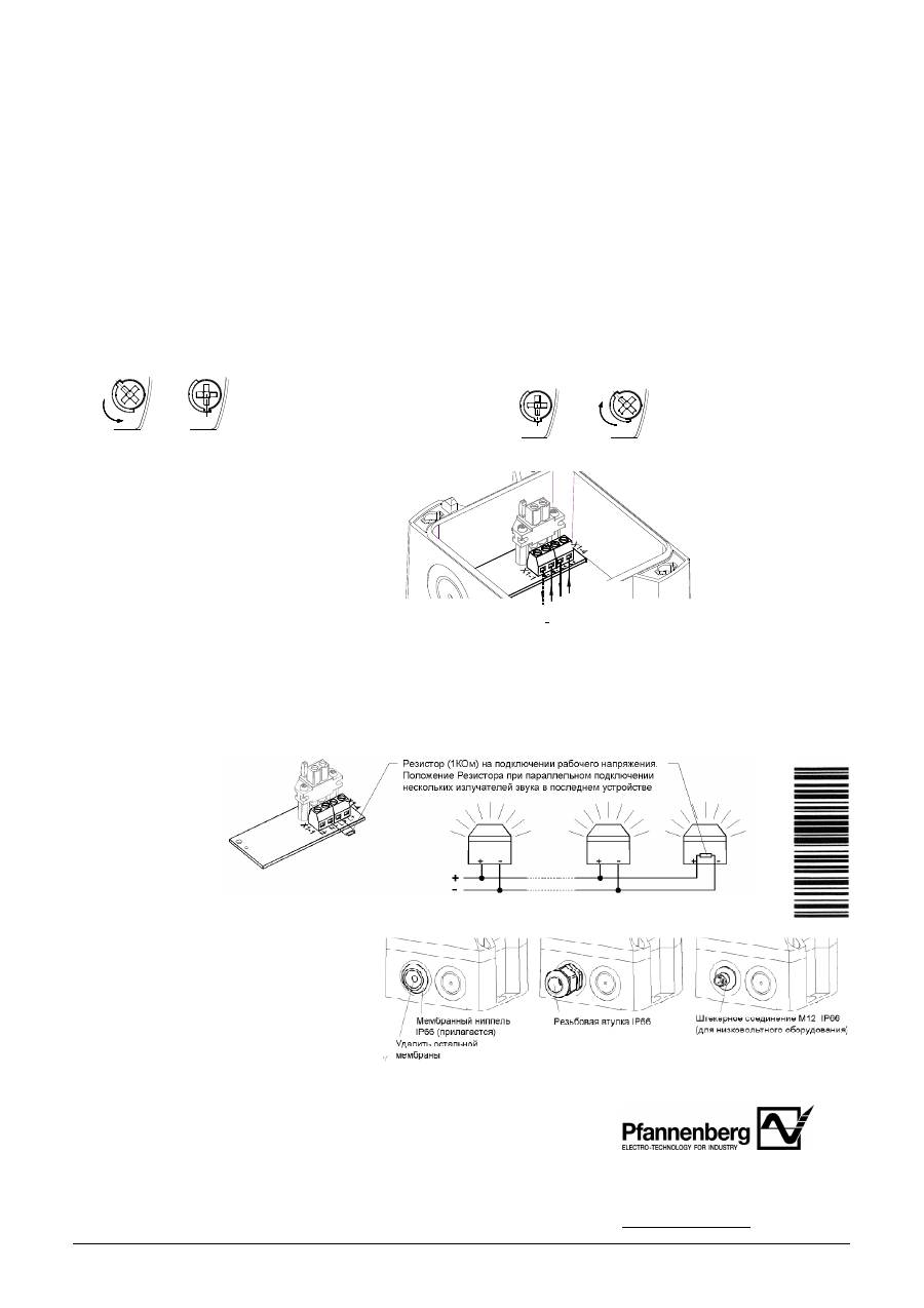
Открывание
корпуса
:
Закрывание
корпуса
3/8
1.
2.
3/8
1.
2.
Устройство
поставляется
в
открытом
состоянии
.
В
качестве
аксессуаров
предлагаются
пломбировочные
пробки
.
Электрическое
подключение
:
Опция
SSM (
Модуль
плавного
пуска
) (
только
24
В
пост
.
тока
):
-
Максимальный
пусковой
ток
2,1
А
-
К
устройству
подводится
напряжение
питания
,
превышающее
7
В
-
Резистор
контроля
цепи
Диапазон
рабочего
напряжения
: 18 – 30
В
пост
.
тока
Резистор
контроля
цепи
:
Кабельный
ввод
Для
сохранения
имеющегося
класса
защиты
в
предусмотренные
отверстия
должны
быть
установлены
кабельные
вводы
класса
IP 66.
Поставляемый
мембранный
ниппель
можно
заменить
резьбовой
втулкой
или
штекерным
соединением
М
12
с
фланцем
М
20.
Техническое
обслуживание
и
поддержание
в
исправном
состоянии
Для
данного
устройства
специальное
техническое
обслуживание
не
требуется
.
Очистка
наружных
поверхностей
осуществляется
с
помощью
слабого
мыльного
раствора
без
использования
растворителей
.
Разрешается
использовать
устройство
только
в
неповреждённом
состоянии
,
согласно
техническим
характеристикам
.
При
изменении
конструкции
,
модификации
оборудования
,
его
неправильном
использовании
и
использовании
не
по
назначению
,
а
также
при
несоблюдении
указаний
данного
руководства
гарантия
теряет
свою
силу
.
Разрешается
использовать
только
оригинальные
запасные
части
.
Ремонт
производится
только
на
предприятии
-
изготовителе
.
Клеммная
колодка
планка
в
нижней
части
Верхнюю
часть
можно
снять
после
поворота
винтов
крышки
.
Корпус
закрывается
путём
поворота
винтов
крышки
до
фиксации
в
конечном
положении
.
Pfannenberg GmbH
Werner-Witt-Straße 1
·
D- 21035 Hamburg
Tel.: +49/ (0)40/ 734 12-0
Fax: +49/ (0)40/ 734 12-101
technical.support @pfannenberg.com
http://www.pfannenberg.com 0912014
X1
Betriebsspannungs-
anschluss
N
L
+
Подключение
рабочего
напряжения
