Partner PFT3540 B: instruction
Class: Gardening equipment
Type:
Manual for Partner PFT3540 B

Mod. POLO - POLO 2004 -
URSUS - MEPPY
INSTRUCTION MANUAL
LIBRETTO D’ISTRUZIONI
IMPORTANT INFORMATION: Please read these instructions
INFORMAZIONI IMPORTANTI: Leggere le istruzioni attenta-
carefully and make sure you understand them before using this
mente e capirle bene prima di usare l’utensile. Conservare
unit. Retain these instructions for future reference.
per ulteriore consultazione.
BETRIEBSANWEISUNG
HASZNÁLATI ÚTMUTATÓ
WICHTIGE INFORMATION: Lesen Sie diese Hinweise zur
Jótállást vállalni csak rendeltetésszerüen használatba vett
Handha-bung des Geräts aufmerksam durch. Verwenden
gépekre tudunk. Kérj ü hogy a gép használatba vétele elött
Sie es erst, wenn Sie sicher sind, daß Sie alle Anweisungen
gondosan olvassa el a kezelési utasításokat.
verstanden haben und gut aufbewahren.
EΓXEIPI∆IO XEIPIΣMOE
MANUEL D’INSTRUCTIONS
ΣHMANTIKEΣ ΠΛHPOΦOPIEΣ: ∆ιαβάστε προσεxτιxά αvτές
RENSEIGNEMENTS IMPORTANTS: Avant d’utiliser cet appareil,
τις οδηγίες xαι Φροvτίστε vα τις xαταvoήσετε αvτό το µηχάvηµα
veuillez lire atentivement les instructions et assurez-vous de les avoir
xαι Φuλάξτε το για vα το σuµβulλεύεστε στ µέλλοv.
comprises. Conservez les instructions pour référence ultérieure.
NÁVOD K POUŽÍVÁNÍ
HANDLEIDING
DŮLEŽITÁ INFORMACE! Než začnete stroj použivat přečtěte
BELANGRIJKE IMPORTANTS: Lees deze handleiding aan-
si prosím velmi pozorně tyto instrukce a ujistěte se, že jste jim
dachtig en zorg dat u ailes begrijpt alvorens de kettingzaag te
porozuměli. Uschovejte si tento návod pro použití i v budoucnu.
gebrulken en be-waar ze voor toekomstige raadpleging.
PRÍRUČKA
BRUKERHÅNDBOK
IMPORTANT INFORMATION: Please read these instructions
VIKTIG INFORMASJON: Les disse anvisningene nøye og
carefully and make sure you understand them before using this
forsikre deg om at du forstår dem før du bruker enheten og
unit. Retain these instructions for future reference.
oppbevar dem for sen-ere bruk.
INSTRUKCJA OBSŁUGI
OHJEKIRJA
Gwarancja traci ważność w przypadku używania urządzenia
TÄRKEÄÄ TIETOA: Lue nämä ohjeet huolellisesti ja varmista,
do celów innych niż wymienione w instrukcji obsługi. Prosimy o
että olet ymmärtänyt ne, ennen kuin alat käyttää tätä laitetta ja
uważne przeczytanie instrukcji oraz o stoowanie się do zaleceń
säilytä myöhempää tarvetta varten.
i wskazówek w niej zawartych.
BRUKSANVISNING
ИНCTPYKЦИИ
VIKTIG INFORMATION: Läs instruktionerna noggrant och för-
BAЖHЫE CBEДEHИЯ: Bнимaтeльнo пpoчитать инстрyкции
säkra dig om att du förstår dem innan du använder utrustningen
и хрoщo их пoнять, пepeд тeм как пoльзoвaтьcя блoкoм.
och spara dem för framtida behov.
Хpaнить инcтpyкции для дaльнейшиx кoнcyльтаций.
BRUGERHÅNDBOG
KASUTUSJUHEND
VIGTIGE OPLYSNINGER: Læs instruktionerne omhyggeligt,
TÂHTIS INFORMATSIOON: Lugege kasutusjuhend enne
før du bruger enheden og gemme til senere henvisning.
seadme kasutamist kindlasti põhjalikult läbi ning veenduge,
et olete kõigest täpselt aru saanud.
MANUAL DE INSTRUCCIONES
NAUDOJIMOSI INSTRUKCIJA
INFORMACIÓN IMPORTANTE: Lea atentamente las instruccio-
SVARBI INFORMACIJA: prieš pradedant dirbti įrenginiu,
nes y asegúrese de entenderlas antes de utilizar esta aparato.
prašome atidžiaiperskaityti šią instrukciją ir įsitikinti, kad viską
Conserve las instrucciones para la referencia en el futuro.
supratote. Išsaugokite ją tolimesniam naudojimui.
MANUAL DO OPERADOR
KNJIŽICA Z NAVODILI
INFORMAÇÕES IMPORTANTES: Queira ler cuidadosamente
POMEMBNA NAVODILA: Pozorno preberite navodila. Dobro jih
estas instruções e tenha certeza de entendë las antes de usar
morate razumeti, preden začnete uporabljati to orodje.
a serra e guarde para consulta futura.

Due to a constant product improvement programme,
La casa produttrice si riserva la possibilità di variare
GB
IT
the factory reserves the right to modify technical
caratteristiche e dati del presente manuale in
details mentioned in this manual without prior notice.
qualunque momento e senza preavviso.
This manual has been prepared for use with different
Questo manuale è stato redatto per essere utilizzato
models of Petrol Tiller having different shapes and
con diversi modelli di motozzappe con forme ed
equipment.
equipaggiamenti differenti.
Im Sinne des Fortschritts behält sich der Hersteller das
A gyártó cég fenntartja a jogot arra, hogy a használati
DE
HU
Recht vor, technische Änderungen ohne vorherigen
utasitásban megadott adatokon és technikai
Hinweis durchzuführen.
tulajdonságokon bármikor és elözetes bejelentés
nélkül változtasson.
Diese Bedienungsanleitung wurde für verschiedene
Ez a kézikönyv, azért lett létrehozva, hogy segítségre
Benzin Bodenhacken geschrieben.
legyen a különböző formájú és felszerelésű elektro-
La Maison se réserve la possibilité de changer des
mos kapák használatában.
FR
caractéristiques et des données de ce manuel à
Λόγω προγράμματος συνεχο'θς βελτíωσης προιόντων,
n'importe quel moment et sans préavis.
GR
το εργοστάσιο επιφυλάσσεται του δικαιώματος να
Ce Manuel a été rédigé pour être utilisé avec
τροποποιεί τις τεχνικές λεπτομέρειες που αναφέρονται
différents modèles de houes à moteur avec formes
στο εγχειρίδιο αυτό χωρίς προηγούμενη ειδοποίηση.
et équipements différents
Door konstante produkt ontwikkeling behoud de
NL
fabrikant zich het recht voor om rechnische specicaties
zoals vermeld in deze handleiding te veranderen
zonder biervan vooraf bericht te geven.
Vzhledem k pokračujícím inovacím si vyrobce
CZ
výhrazuije právo mínit technické hodnoty uvedené v
Deze handleiding is samengesteld voor het gebruik
této přiručce bez predčhozího upožornení.
van verschillende modellen van Petrol Tiller van
verschillende afmetingen en accessoires.
Obsah této příručky lze použít pro různé typy motoro-
vých kultivátorů, lišících se tvarem i vybavením
Produsenten forbeholder seg all rett og mulighet til
NO
å forandre tekniske detaljer i denne manualen uten
Na základe programu neustáleho zlepšovania produktov
SK
forhåndsvarsel.
si výrobný závod vyhradzuje bez predchádzajúceho
upozornenia právo na zmenu technických parametrov
Denne håndboken er beregnet til bruk med ulike
uvedených v tejto príručke.
modeller av Petrol Tiller, som har forskjellige fasonger
og utstyr.
Táto príručka slúži pre rôzne modely benzínových
kul tivá toro v roz ličn ých tv arov a s rô zn ym
Jatkuvan tuotteen parannusohjelman tähden valmistaja
FI
príslušenstvom..
pidättää oikeuden vaihtaa ilman ennakkovaroitusta
tässä ohjekirjasessa mainittuja teknisiä yksitsyikohtia.
W związku z programem ciąglego ulepszania swoich
PL
wyrobów producent zastrzega sobie prawo do
Tätä opasta on muutettu, jotta sitä voidaan käyttää
wprowadzania zmian w szczególach technicznych
eri moottorijyrsinmallien kanssa, joiden muodot ja
wymienionych w tej instrukcji bez uprzedniego
varusteet eroavat toisistaan
zawiadomienia. Instrukcja jest częścią wyposaże.
Tilverkaren reserverar sig rätten att ändra fakta och
SE
Książeczka ta została opracowana do wykorzystania
uppgifter ur handboken utan förvarning.
dla różnych modeli motyk mechanicznych o różnych
Denna bruksanvisning är skriven för olika modeller
formach i wyposażeniu
av elektriska gräsklippare med olika utseende och
utrustning.
Компания производитель сохраняет за собой
RU
право изменять характеристики и данные в
Producenten forbeholder sig ret til ændringer, hvad
DK
настоящем руковдстве, в любой момент и без
angår karakteristika og data i nærværende instruktion,
предварительного извещения.
når som helst og uden varsel.
Данное руководство было подготовлено для
Denna bruksanvisning är skriven för olika modeller
использования с различными моделями машин
av bensindrivna jordfräsar med olika utseende och
бензиновая почвенная фреза различных форм и
utrustning
оборудования
La rma productora se reserva la posibilidad de
ES
Tootja jätab endale õiguse muuta käesolevas
cambiar las características y datos del presente
EE
kasutusjuhendis kirjeldatud omadusi ja andmeid
manual en cualquier momento y sin previo aviso.
suvalisel hetkel ja sellest eelnevalt ette teatamata.
El presente manual se ha redactado para utilizarse
See kasutusjuhend on koostatud kasutamiseks
con distintos modelos de azadas eléctricas con
bensiinimootoriga pinnasefreesi eri mudelitega, millel
formas y equipos diferentes
võib olla erinev kuju ja varustus.
A casa productora se reserva a possibilidade de
Kadangi gaminis nuolat derinamas, įmonė palieka
PT
LT
variar características e dados do presente manual em
sau teise keisti techninius duomenys, apie kuriuos yra
qualquer momento e sen aviso prévio.
nurodyta šioje instrukcijoje, be išankstinio pranešimo.
Este manual foi redigido para ser utilizado em diver-
Instrukcija buvo paruošta įvairių benzininė dirvinė fre-
sos modelos de Motoenxada, com forma e equipa-
za naudojimui, kurios tūri įvairias formas ir įrangą.
mento diferentes
Proizvajalec si pridržuje pravico do spremembe
SL
karakteristik in podatkov v tem priročniku v katerem
koli trenutku brez predhodnega obvestila.
Ta priročnik je namenjen uporabi različnih modelov
motornega okopalnika različnih oblik in z različno
opremo.
2
We wish to thank you for choosing our petrol tiller. We are condent that the high quality of our machine will meet with
your satisfaction and appreciation and that your vacuum cleaner will give you long-lasting service.Before starting to use
your machine, make sure to read with care this manual, which has been purposely drawn up to provide you with all the
necessary information for proper use, in compliance with basic safety requirements.
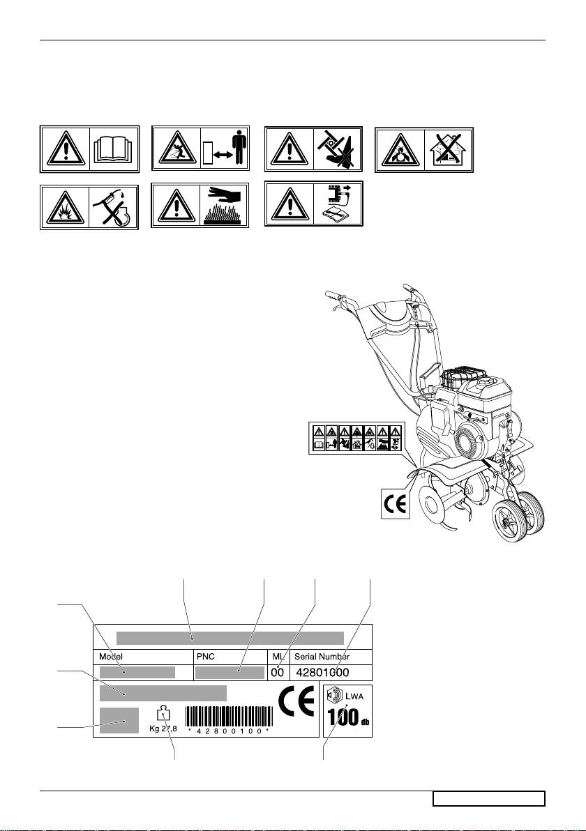
1 2 3 4
5 6 7
Caution! Read the instruction manual before
1
use
2
Keep other people well away from the danger
area!
3
Caution!Cutting tool and moving parts.
4
Risk of breathing in toxic gases ! Do not use the
appliance in closed or poorly ventilated environ-
ments.
5
Risk of explosion ! Do not top up with fuel with
engine running.
6
Caution! Hot surface
Caution! Switch off the engine and disconnect
7
the spark plug before undertaking any mainte-
nance work
1 Manufacturer
2 Model
3 Product number
4 Maintenance lever
5 Serial number
6 Type
7 Engine info
8 Weight
9 Sound power level
ENGLISH -
1
1
3
4
5
2
6
7
8
9

SAFETY RULES
Training
a)Persons under 16 years of age and persons who are
replace the fuel tank cap and tighten it down rmly.
not acquainted with the user instructions must not
f)The machines with internal combustion engines
use the petrol tiller.Do not allow children or anyone
must never be operated in closed environments
who has not understood these instructions to use the
on account of the danger of carbon monoxide
petrol tiller. A minimum age for using the machine
poisoning.
can be xed by local regulations.
g)The safety distance, which is set by the length
b)The operator is responsible for the safety of other
of the handle, must always be kept. Furthermore,
people in the working area. Keep children and do-
when the engine is working, never run; you must
mestic animals at a safe distance when the petrol
always walk.
tiller machine is in use.
h)articular precautions must be taken when using
c)This petrol tiller may be used exclusively for breaking
the rotary hoe machine on slopes or downhill
and loosening natural soil. Its use is not allowed for
stretches:
other purposes (e.g. for cutting branches).
use appropriate antislip footwear
d)Work only when there is sufcient light.
watch where you put your feet
e)Before you start using the petrol tiller machine,
always move sideways with respect to the slope;
make sure to remove any objects or obstacles that
never move uphill or downhill
might be present. While you are using the petrol
take great care when changing direction
tiller machine, keep your eyes open for the possible
do not work on excessively steep slopes.
presence of such objects that may have been left
i)Never use the petrol tiller machine with faulty guards
on the ground.
or protections or without safety devices installed and
Setting up and operating the engine
in proper order.
a)When using the petrol tiller machine, wear strong
j)For reasons of safety, the engine must never exceed
footwear (boots or heavy shoes) and long trou-
the number of revs (r.p.m.) indicated on the data
sers.
plate.
b)Before you start working, make sure that the cutting
k)Take care when starting the engine and make sure
tools are securely fastened. If they were to present
to follow the user instructions. When the engine is
any major damage, they must be replaced.
turning, it is absolutely necessary to prevent anybody
c)During engine startup, under no circumstances lift
from approaching the moving parts.
up the machine.
d)Turn off the engine and disconnect the cap of the
Maintenance and storage
spark plug whenever:
a)Make sure that all nuts, bolts and screws are kept
removing the protection devices
well tightened down so as to work in conditions of
transporting, lifting or displacing the machine from
perfect safety.
the working area
b)Never leave the machine with fuel in the tank
carrying out maintenance or cleaning
where the fuel vapours could reach naked ames
carrying out any operation on the cutting tools
or sparks.
c)Give the engine enough time to cool off before
leaving the petrol tiller machine unattended.
CAUTION! The tools keep turning for a few secon-
putting the equipment in any narrowly enclosed
ds even after the engine has been turned off.
environment.
e)CAUTION! The fuel is highly inammable:
d)Keep the engine, silencer, battery compartment
keep the fuel only in the fuel cans provided for that
and petrol tank free from grass, leaves and excess
purpose
lubricant in order to reduce the danger of re.
pour the fuel into the tank only in the open air and
e)For safety reasons, make sure to replace worn-out
make sure not to smoke
or damaged parts in due time.
fill up the fuel tank before starting the engine.
f)Should you drain off the fuel tank in order to store
Under no circumstances open the fuel tank cap or
the rotary hoe machine away for the winter, make
add petrol when the engine is running or when it
sure to carry out this job in the open air.
is still hot
g)Install the cutting tools following the corresponding
if the petrol has overowed, do not under any circu-
instructions and use exclusively tools bearing the
mstances start up the engine. Take the machine out
Manufacturer's or Supplier's name or trademark and
of the area where the fuel has been spilt and avoid
the reference number.
any source of possible ignition until the petrol fumes
h)To protect your hands during disassembly or as-
have dissipated
sembly of
the cutting tools, wear suitable protective
gloves.
ENGLISH -
2

DESCRIPTION (starts at page II)
1 Handles
12 Clutch lever
2 Accelerator
13 Reverse lever
3 Dash-board
14 Side disk
4 Rod
15 Oil ller cap
5 Transport wheels
16 Oil drain plug
6 Hoeing blades
17 START/STOP switch
7 Protection guard
18 Filter cap for gearbox
8 Fuel tank
19 Drain plug for gearbox
9 Spark plug
20 Motor
10 Engine startgrip
21 Handle plate
11 Reduction gear
22 Safety handle
ASSEMBLY
Skid (4): indroduced the skid into the seat an the frame
(23) and x with cotter pin (26).
MOD. 1
(Fig.BI)
Wheel (5):
Mount the wheel rod (27) an the frame (23)
and then x with screw, washer and nut (28). Introduce
MOD. 2 (Fig.BII)
cotter pin (29).
Accelerator lever (Governor) (2): (this refers only to the
MOD. 4 (Fig.BIII)
version with 4-stroke engine). Fix the governor to the
ASSEMBLY OF: HANDLES - SKID - WHEEL - ACCE-
handles (1) by means of screw and nut (30).
LERATOR LEVER - OFF-SWITCH.
Switch (17): (this refers anly to the version with 2-stroke
Handles (1): mount handle-plate (21) in the frame (23)
engine). Introduce the terminals of grounding cables (31)
and x it with four screws, washers and nuts (24). Now
into the xing spots of the switch.
introduce the two handles (1) into the handle-plate and
x them with screws, washers and wing screws(25).
MOD. 4 (Fig.BIV)
SAFETY DURING USE
Before you start working, make sure to remove
The operator is responsible for the safety of other people
any objects or obstacles that may have been left
in the working area.
on the lawn.
ENGINE ADJUSTMENTS
Refer to the engine manufacturer's maintenance
CAUTION:- 0.6l Oil must be added to the engine before
manual.
use.
ADJUSTMENT OF HANDLES (for the models where it is included only)
MOD. 1 (Fig.EI)
MOD. 2 (Fig.EII)
MOD. 4 (Fig.EIII)
ENGLISH -
3
OPERATION
MOD.1 (Fig.FI-FII-FIII-FIV-FV)
MOD.2
(Fig.FVI-FVII-FVIII-FIX-FX)
Once the machine has been set up properly, start the
Once the machine has been set up properly, start the
engine as follows:
engine as follows:
Before starting work, it is necessary to carry out the
Before starting work, it is necessary to carry out the
following:
following:
- set the trasport wheels (5) upwards.
- set the trasport wheels (5) upwards.
a)Engines with choke system:
a)Engines with choke system:
if
the model is equipped with an accelerator, when the
if the model is equipped with an accelerator, when
engine is cold, position the accelerator lever (2) on
the engine is cold, position the accelerator lever (2)
START
on START
Engines with primer system:
Engines with primer system:
Press the fuel-enrichment pump located on the car-
Press the fuel-enrichment pump located on the car-
burettor 3 or 4 times.if the model is equipped with an
burettor 3 or 4 times.if the model is equipped with an
accelerator, position the accelerator lever (2) on MAX.
accelerator, position the accelerator lever (2) on MAX.
b) Grip the engine start grip (10) and pull the starter
b) Grip the engine start grip (10) and pull the starter
rope gently until you feel the resistance caused by
rope gently until you feel the resistance caused by
compression. Release the handle; then give the starter
compression. Release the handle; then give the starter
rope a sharp tug.
rope a sharp tug.
For further information and explanations, read careful-
For further information and explanations, read careful-
ly the user instruction manual of the engine.
ly the user instruction manual of the engine
Initially position the hook (15) of the forward drive cable
WARNING! Never keep the two handles (12-13)
and the hook (16) of the reverse clutch cable in the holes
activated at the same time. It may cause damage
(II°) of the respective handles (1
2-13).
to the belts and pulleys
Should the handle action not follow the cutter clutch,
WHEN THE TILLER IS ON: in order to make the tiller
position the hook into hole (I°) of the handle, while on the
blades (6) run, handle (12) must be depressed. When
contrary insert it into hole (III°) should the cutters remain
working with the tiller, keep the handle depressed.
engaged even on release of the handle itself.
If the handle is released, the tiller blades will come to
WARNING! Never keep the two handles (12-13)
a stop.
a
ctivated at the same time. It may cause damage
Depress the skid in order to work in depth and decrease
to the belts and pulleys.
the pressure to move forwards.
WHEN THE TILLER IS ON: in order to make the tiller bla-
REVERSE-GEAR: for engaging the reverse-gear, only
des (6) run, handle (12) must be depressed. When working
handle (13) must be actuated.
with the tiller, keep the handle depressed. If the handle is
How to stop the engine: for this purpose, shift the accele-
released, the tiller blades will come to a stop.
rated lever into STOP position.
Depress the skid in order to work in depth and decrease
the pressure to move forwards.
The four cutter stars (6) can be pulled off, and the combina-
tion of cutters allows working widths from
25 to 55 cms.
REVERSE-GEAR: for engaging the reverse-gear, only
handle (13) must be actuated.
For assembly, introduce the blade star (6) to the rotary
shaft (N) and make the two holes (P) match: then introduce
How to stop the engine: for this purpose, shift the accele-
pin (R) by fastening it with the respective spring. Make sure
rated lever into STOP position.
that the hoeing blades are assembled in the right direction,
The four cutter stars (6) can be pulled off, and the combina-
i.e. the cutting angle showing forward.
tion of cutters allows working widths from
25 to 55 cms.
For assembly, introduce the blade star (6) to the rotary
shaft (N) and make the two holes (P) match: then introduce
pin (R) by fastening it with the respective spring. Make sure
that the hoeing blades are assembled in the right direction,
i.e. the cutting angle showing forward.
ENGLISH -
4

MOD.3 (Fig.FXI-FXII)
MOD.4 (Fig.FXIII-FXIV)
Once the machine has been set up properly, start the
Engine as follows:
engine as follows:
- Make sure that the clutch is disengaged (Handle (12)
1) 2-stroke engine version, position the switch (17) on
must be down-wards).
START to enable engine startup.
-
Lower lever of the safety handle (22) and insert the
1.a) Grip the starting handle (10) and pull the engine
reatining spring (38) into the appropriate notch.
start grip gently until you feel the resistance caused by
a)Engines with CHOKE SYSTEM:
compression. Release the handle; then give the starter
if
the model is equipped with an accelerator, when the
rope a sharp tug.
engine is cold, position the accelerator lever (2) on
2
) 4-stroke engine version:
START
2.a)Engines with choke system:
Engines with PRIMER SYSTEM:
P
ress the fuel-enrichment pump located on the car-
if the model is equipped with an accelerator, when
burettor 3 or 4 times.If the model is equipped with an
the engine is cold, position the accelerator lever (2)
accelerator, position the accelerator lever (2) on MAX.
on START
b) Start engine.
2.b)Engines with primer system:
Grip the starting handle (4) and pull the starter rope
Press the fuel-enrichment pump located on the carbu-
gently until you feel the resistance caused by compres-
rettor 3 or 4 times, if the model is equipped with an
sion. Release the handle; then give the starter rope a
accelerator, position the accelerator lever (2) on MAX.
sharp tug.
2.c) Grip the starting handle (10) and pull the starter
For further information and explanations, read careful-
rope gently until you feel the resistance caused by
ly the user instruction manual of the engine.
compression. Release the handle; then give the starter
rope a sharp tug.
Before starting work, it is necessary to carry out the
following:
For further information and explanation, read carefully
the Engine Manufacturers instruction manual.
- adjust the skid (4) according to the soil and to hoeing
depth to be obtained. For this job, introduce pin (39) in
Before starting work, it is necessary to carry out the
one of the holes on the skid and x it with the cotter.
following:
When engine is running. For making the hoeing blades
-adjust the skid (4) according to the soil and the depth of
turn proceed as follows:
hoe which is required, to do this insert the cotter pin (32)
in one of the holes on the skid and x it with clip.
- engage the clutch; for this operation pull the clutch lever
(1
2) upward until engaging is completed. The lever is
- set the trasport wheels (5) upwards. For this purpose
hold in this position by stop lever (40).
move the wheel rod (33) in the upper hole and x it
with cotter pin (34).
- Seize the safety lever (22) together with the handles.
By doing this, the retaining spring is released. Now, if
WHEN THE ENGINE IS ON: in order to make the tiller
the handle bars are released the engine woulf auto-
blades (6) run, handle (12) must be depressed. When
matically stop.
working with the tiller, keep the handle depressed. If
the handle is released, the hoeing blades will come
How to stop the engine: for this purpose, shift the acce-
to a “stop”
lerated lever into STOP position.
Depress the skid in order to work in depth and decrease
Disengagement of the clutch lever: pull retaining lever
the pressure to move forwards.
(40) in order to remove it from the hold position (For fa-
cilitating release, pull the lever slightly backwards). Now,
HOW TO STOP THE ENGINE:
let the handle go in oder to effect disengagement.
- 2-stroke engine version, set the interrup button to
STOP.
- 4 stroke engine version, set accelerator lever to STOP.
HOW TO MOUNT THE HOEING BLADES (6): mount
the hoeing blades an the rotary shaft (35) and make
two holes (36) coincide, then t pin (37) and x with the
respective spring.
ENGLISH -
5

MAINTENANCE
Caution! Switch off the motor and disconnect the spark
plug before undertaking any maintenance work.
Check regulary all screws and nuts for tightness
Engine: consult the instruction Manual of the engine-maker.
Wheels: axles must kept clean and sufciently greased
MOD.1 (Fig.GI-GII)
MOD.3 (Fig.GV-GVI)
Clutch lever (12): When the clutch wire is too slack and
Reduction gearbox (11): this unit contains approx. 150
does not permit a correct engagement, an adjustment
ml oil of the SAE 20/40 grade. Check the oil level through
of the clutch wire must be carried out by introducing the
the ller cap (18). After 60 operation hours change the
tie-bolt (41) in one of the next holes (X) of lever (12).
oil. for this purpose use the respective drain plug (18)
and the ller cap (19)
Drive blet (Z): For replacement of the belt, the following
steps must be carried out: take off the casing (T) by un-
Any detriment due to lack of checking the oil-lever or
screwing screw (S); replace the belt; then re-assemble
incorrect oil-change are not covered by guarantee.
the whole.
Clutch lever (12): When the clutch wire is too slack and
REVERSE-GEAR
does not permit a correct engagement, introduce spring
(47) into one of the subsequent holes on plate (48).
Restoring of belt tension (Q): When the clutch wire is
too slack and does not permit a correct engagement,
an adjustment of the clutch wire must be carried out
MOD.4 (Fig.GVII-GVIII)
by introducing the tie-bolt (42) in one of the next holes
Ball bearing lubricate periodically the entrance shaft
(Y) of lever (13).
to the reduction gear. For this reason, pour SAE 30
Drive-belt (Q): For replacing the belt, take off housing (T)
oil into oiler (A) which is located below the connection
by loosenisng screws (S). Then replacing the belt, take
ange.
off housing (T) by loosening screwa (S). Then replace
Reduction gearbox (11): this unit contains approx.
the belt and re-assemble the whole.
0.500 Kg oil of the SAE 120/140 grade. Check the oil
l
evel through the plug (18). After 20 operation hours
MOD.2 (Fig.GIII-GIV)
change the oil. for this purpose use the respective drain
Clutch lever (12): When the control cable works loose,
plug (18) and the ller cap (19)
no longer allowing the relevant coupling, the clutch cable
Any detriment due to lack of checking the oil-lever or
must be adjusted:
incorrect oil-change are not covered by guarantee.
- Unlock lock nut (43) and unscrew screw (44) for two
complete revolutions.
Clutch lever (12): When the wire slackens, thus not
- Fix position of screw (44) by tightening lock nut (43).
allowing correct engaging of the clutch, adjustment must
B
y acting on lever (12) make sure that cutters have
be effected. For this, turn screw (48) whitch is located
engaged. If not, repeat the operations above.
on the lever and on the steeldech.
Drive blet (Z): For replacement of the belt, the following
Drive blet (Q): These are subject to wear; therefore
steps must be carried out: take off the casing (T) by
the original tensioning should be restored or the belt de
unscrewing screw (S); replace the belt; then re-assem-
changed. For replacing te belts, proceed as follows:
ble the whole.
- release spring (49), loosen screw (50). (Is this way,
VERSION WITH REVERSE-GEAR
the bowden wire of the clutch does not hold the spring
Restoring of belt tension (Q): When the control cable
under tension).
works loose, no longer allowing the relevant coupling,
- release the two springs (51) and remove them from their
the clutch cable must be adjusted:
fastening seat.
-
Unlock lock nut (45) and unscrew screw (46) for two
-
take off the housing (52) by unscrewing the four screws
complete revolutions.
(53).
- Fix position of screw (46) by tightening lock nut (45).
By acting on lever (13) make sure that cutters have
- Loosen the two screws (54) and push the belt giudes
engaged. If not, repeat the operations above.
away (55) in order to permit changing of the belt.
Drive-belt (Q): For replacing the belt, take off housing (T)
After replacement of the belts, remount all part.
by loosenisng screws (S). Then replacing the belt, take
Be careful, during the remounting operation, to place the
off housing (T) by loosening screwa (S). Then replace
nylon guides (56) with the recess facing the operator. Now,
the belt and re-assemble the whole.
adjust tensioning of the cloutch wire.
ENGLISH -
6

GUARANTEE AND GUARANTEE POLICY
If any part is found to be defective due to faulty manufacture
Failures not covered by guarantee
within the guarantee period, Husqvarna Outdoor Products,
- Replacing worn or damaged blades
through its Authorised Service Repairers will effect the
- Failures as a result of not reporting an initial fault.
repair or replacement to the customer free of charge
- Failures as a result of sudden impact.
providing:
- Failures as a result of not using the product in accordance
a) The fault is reported directly to the Authorised Re-
with the instructions and recommendations contained in
pairer.
this Operator’s Manual.
b) Proof of purchase is provided.
- Machines used for hire are not covered by this gua-
c) The fault is not caused by misuse, neglect or faulty
rantee.
adjustment by the user.
- The following items listed are considered as wearing parts
d) The failure has not occurred through fair wear and
and their life is dependent on regular maintenance and
tear.
are, therefore not normally subject to a valid warranty
e) The machine has not been serviced or repaired, taken
claim: Blades, Electric Mains cable, Belt
apart or tampered with by any person not authorised by
- C
AUTION!
Husqvarna Outdoor Products.
Husqvarna Outdoor Products does not accept liability
f) The machine has not been used for hire.
under the warranty for defects caused in whole or part,
g) The machine is owned by the original purchaser.
directly or indirectly by the tting of replacement parts
h) The machine has not been used commercially.
or additional parts that are not either manufactured or
This guarantee is additional to, and in no way diminishes
approved by Husqvarna Outdoor Products, or by the
the customers statutory rights.
machine having been modied in any way..
Failures due to the following are not covered, therefore
it is important that you read the instructions contained in
this Operator’s Manual and understand how to operate
and maintain your machine:
EC DECLARATION OF CONFORMITY
I, the undersigned Bengt Ahlund, of Husqvarna Outdoor Products Italia Spa, Via Como 72, 23868 Valmadrera (LC).
Certify that the Petrol Wheeled Rotary:
Category .................................................................Petrol Wheeled Rotary
Make .......................................................................Husqvarna Outdoor Products
Conforms to the specications of Directive 2000/14/EEC
Type ........................................................................A
Version....................................................................B
Width of cut.............................................................C
Guaranteed sound power level...............................D
Measured sound power level..................................E
Sound pressure livel at the ear ...............................F
Vibration of the handle ............................................G
Diameter of cuttersr ................................................H
Cutter rpm...............................................................I
(See the last page for references)
Working equipment .................................................4/6 star cutter with 4 cutting tools each
Type of Cutting Device ............................................Rotary Blade
Identication of Series ............................................See Product Rating Label
Conformity Assesment Procedure ..........................ANNEX VI (<3kW), ANNEX V (>3kW)
Notied Body. .........................................................Nr. 0470 - NEMKO AS
Gaustadalleen 30 - PO Box 73 Blindern
0314 OSLO - Norway
Other Directives ......................................................98/37/EC, 2002/88/EC, 2004/108/EC
& applicable standards normative ..........................EN709,EN ISO14982,EN1033,EN ISO 3744,EN ISO11201
Technical Manager
Husqvarna Outdoor Products Italia spa
Via Como 72 - 23868 Valmadrera (LC)
ENGLISH -
7
