Bowers & Wilkins CWM DS8: instruction
Class: Household, kitchen appliances, electronics and equipment
Type: Microphone
Manual for Bowers & Wilkins CWM DS8

Custom Installation Series
CWM DS8
Owner’s Manual
and Warranty

Contents
English
Русский
Limited Warranty...........2
Ограниченная
Owner’s Manual............2
гарантия....................20
Руководство по
Français
эксплуатации ............20
Garantie limitée.............4
Manuel d’utilisation.......4
"esky
Záruka .......................23
Deutsch
Návod k pouãití..........23
Garantie .......................6
Bedienungsanleitung.....6
Magyar
Korlátozott garancia ..25
Español
Használati útmutató ...25
Garantía limitada...........8
Manual de
Polski
instrucciones................9
Gwarancja .................27
Instrukcja
Português
uÃytkownika ...............27
Garantia limitada.........11
Manual do utilizador....11
.......................29
Italiano
.....................29
Garanzia limitata.........13
Manuale di istruzioni ...14
.......................31
Nederlands
....................31
Garantie .....................15
Handleiding ................16
Ελληνικά
Περιορισµένη
εγγύηση....................17
Οδηγίεσ Χρήσεωσ ....18
1

where the equipment can be serviced.
In solid wall construction, be prepared to
English
You can call B&W in the UK or visit our
provide a cavity in the wall that extends
web site to get the contact details of
outside the boundaries of the speaker’s
your local distributor.
frame, otherwise bass performance will be
Limited Warranty
compromised.
To validate your warranty, you will need to
Dear customer, welcome to B&W.
produce this warranty booklet completed
The speakers are balanced for half-space
and stamped by your dealer on the date of
mounting (ie flush in a wall or ceiling).
This product has been designed and
purchase. Alternatively, you will need the
Placement near a wall/ceiling junction or in
manufactured to the highest quality
original sales invoice or other proof of
a corner may give rise to too much bass
standards. However, if something does go
ownership and date of purchase.
and a boomy quality to the sound. Try to
wrong with this product, B&W
keep the speakers at least 0.5m (20in) from
Loudspeakers and its national distributors
wall/ceiling edges.
warrant free of charge labour (exclusion
may apply) and replacement parts in any
The following sections give guidance on
Owner’s manual
country served by an official B&W
optimum positioning, but this may be
distributor.
modified in line with domestic constraints.
This limited warranty is valid for a period of
Introduction
WARNING: The speakers produce a static
five years from the date of purchase or two
magnetic field. They should not be placed
Thank you for purchasing Bowers and
years for electronics including amplified
within 0.5m (20in) of equipment that may
Wilkins CWM speakers.
loudspeakers.
be affected by such a field (eg Cathode
Since its foundation in 1966, the continuing
Ray Tubes in TVs and Personal
Terms and Conditions
philosophy of B&W has been the quest for
Computers).
perfect sound reproduction. Inspired by the
1 The warranty is limited to the repair of
company’s founder, the late John Bowers,
Surround speakers
the equipment. Neither transportation,
this quest has entailed not only high
nor any other costs, nor any risk for
The speakers should be positioned 60cm
investment in audio technology and
removal, transportation and installation
(2 ft) or more above head height.
innovation but also an abiding appreciation
of products is covered by this warranty.
of music and movies to ensure that the
5.1 channel
2 This warranty is only valid for the
technology is put to maximum effect.
If it is desired to use both dipole and
original owner. It is not transferable.
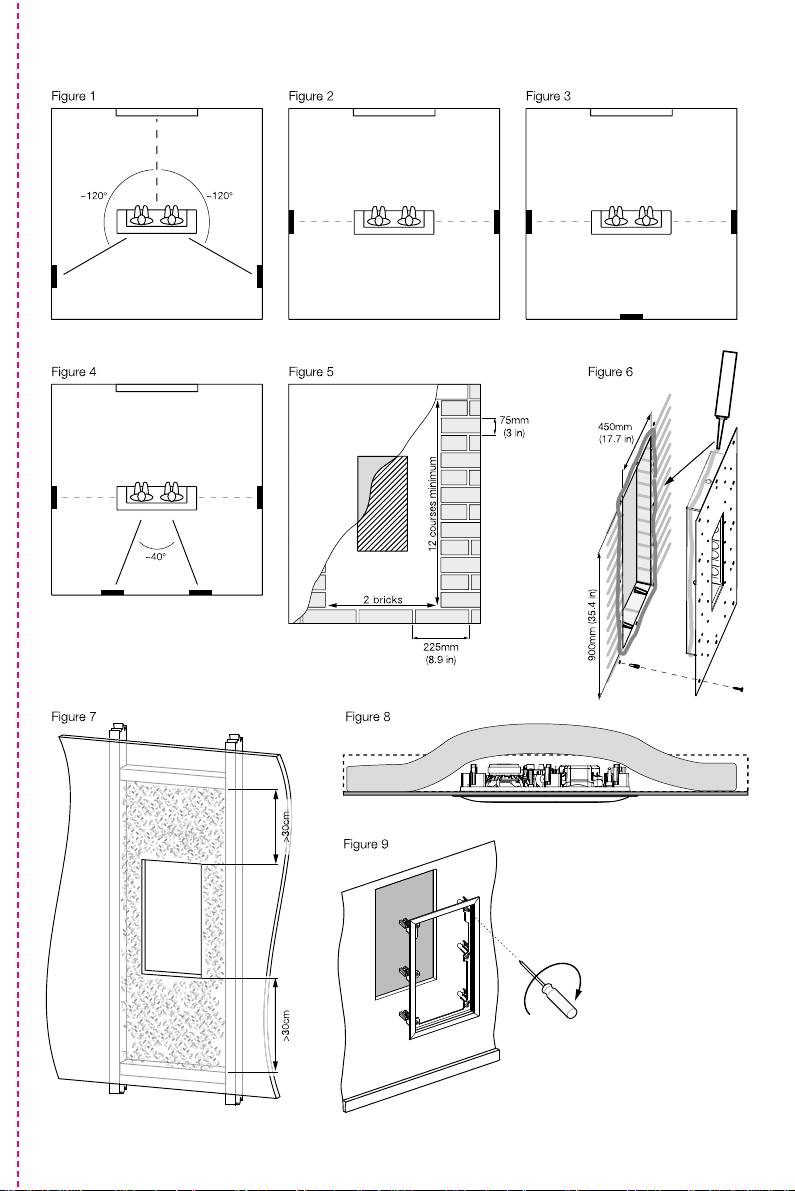
These CWM speakers are primarily
monopole modes, the horizontal angle to
3 This warranty will not be applicable in
intended for in-wall applications, but may
the centre of the listening position should
cases other than defects in materials
equally well be used in-ceiling.
be approximately 120º round from the
and/or workmanship at the time of
centre of the screen. (figure 1)
However, no matter how good the speakers
purchase and will not be applicable:
themselves, they will not deliver their full
If only dipole mode is required, position the
a. for damages caused by incorrect
potential unless properly installed. Please
speakers in line with the centre of the
installation, connection or packing,
read through this manual fully. It will help
listening area. (figure 2)
you optimise the performance of the
b. for damages caused by any use other
6.1 channel
system.
than correct use described in the user
Position two speakers to the sides in line
manual, negligence, modifications, or
B&W distributes to over 60 countries
with the centre of the listening area and
use of parts that are not made or
worldwide and maintains a network of
one centrally behind the listeners (figure 3)
authorised by B&W,
dedicated distributors who will be able to
help should you have any problems your
7.1 channel
c. for damages caused by faulty or
dealer cannot resolve.
unsuitable ancillary equipment,
Position two speakers to the sides in line
with the centre of the listening area and
d. for damages caused by accidents,
Check the contents
two behind the listeners, subtending an
lightning, water, fire heat, war, public
This pack should contain:
angle of approximately 40º. (figure 4)
disturbances or any other cause
beyond the reasonable control of B&W
• wall frame
PREPARING THE LOCATION
and its appointed distributors,
• baffle with drive units and crossover
• grille with backing scrim fabric
e. for products whose serial number has
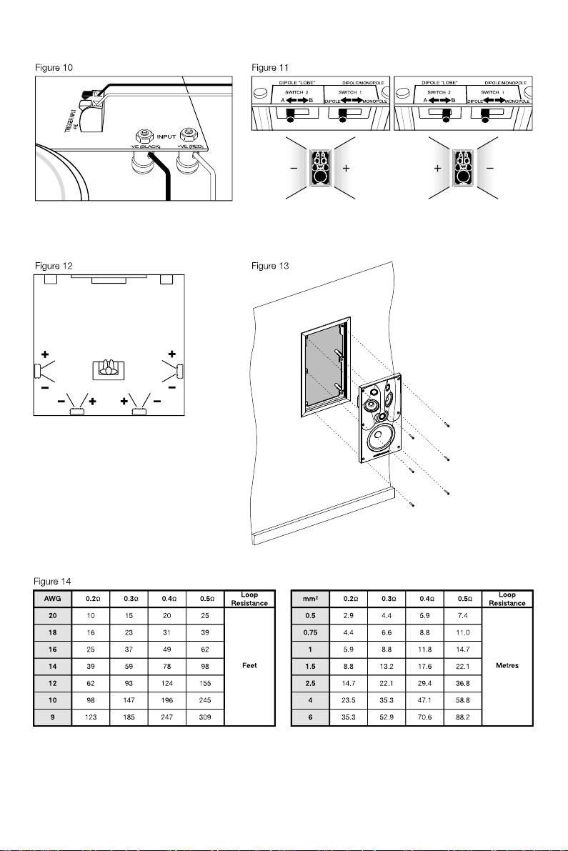
Choosing cable
• paint mask
been altered, deleted, removed or
• mounting template
Excessive resistance in the speaker cable
made illegible,
• 6x M6 screw
wastes power and alters the frequency
f. if repairs or modifications have been
response of the speaker. Always try to keep
executed by an unauthorised person.
Choosing the position
the resistance as low as possible with the
loop resistance preferably below 0.5 ohms
4 This guarantee complements any
Check that there is no conflict with other
for non-critical applications and below
national/regional law obligations of
installations (pipe work, air conditioning,
0.2 ohms for best results. Use the table of
dealers or national distributors and
power cabling etc.). In existing drywall
figure 14 to calculate the minimum gauge
does not affect your statutory rights as
construction, use a stud-finding tool to
of cable required.
a customer.
map the construction accurately and a pipe
detector to scan the proposed installation
If remote switching between monopole and
How to claim repairs under
position.
dipole modes is required, an extra 2-core
warranty
cable is needed for the 12V trigger. At the
Refer to the section drawing of the speaker
speaker end, strip back the insulation to
Should service be required, please follow
and ensure that there is enough clearance
leave bare wire ends. It is usual for the 12V
the following procedure:
behind the plasterboard (sheetrock) for the
trigger output of a processor to take a
clamps to swing out fully.
1 If the equipment is being used in the
3.5mm jack plug.
country of purchase, you should
Avoid installing the speakers in the same
contact the B&W authorised dealer
cavity as flimsy ducting, which may be
Existing drywall construction
from whom the equipment was
induced to rattle.
(retrofit)
purchased.
The speakers are designed to operate
Position the template at the desired
2 If the equipment is being used outside
satisfactorily in a wide range of cavity
location of the speaker. The template is
the country of purchase, you should
volumes, ideally above 20 litres (0.7 cu ft),
marked with both vertical and horizontal
contact B&W national distributor in the
so make sure the volume is not too
centre lines to aid alignment.
country of residence who will advise
restricted by cross studs.
2

Trace round the outer edge of the template
flange as a guide. Depending on the
remove the baffle, loosen the clamps and
and cut neatly just inside the line.
diameter of the router, you may need to
re-tighten them more evenly.
square off the corners with a saw.
To improve the mechanical integrity of the
Fine tuning
wall and reduce the likelihood of rattles, we
In all cases, we recommend not using
recommend you apply a bead of wood glue
cement or mortar to fix the back box into
The choice of monopole or dipole mode
or mastic along the joints between the back
the brick or blockwork. rattles are best
may depend on the type of programme
of the plasterboard and the studs in the
avoided by using flexible mastic and
being played, the speaker’s position in the
vicinity if the speaker.
wedges. (figure 6)
installation and, of course, personal
preference.
Run the cable to the aperture, allowing
Damping the cavity
enough length to comfortably connect the
Multi-channel music often has more
speaker, but not too much, as the excess
Fill the wall cavity or back box, but not the
directional cues in the surround sound field
may rattle against the structure.
space immediately behind the speaker, with
and it may be preferable to have all the
unlined fibreglass or mineral wool matting.
speakers set to monopole. Movie sound is
New drywall construction
The packing density should be just enough
usually more convincing with a diffuse
to comfortably prevent the material from
sound field and it is usual to set at least the
The speaker can be installed once the wall
dropping or sagging over time. In an open
side speakers to dipole. Rear speakers in
is completed in the same manner as
wall cavity, fill to a distance of at least
6.1 and 7.1 installations are sometimes set
retrofitting, but it is easier to position and
30cm (1 ft) above and below the speaker.
to monopole, even if the side speakers are
cut the hole if the optional pre-mount kit is
(figure 7)
set to dipole, but dipole all round is also an
used before the plasterboard (sheetrock) is
option. Experiment to find the best settings
fitted.
In the ceiling, drape the matting at the back
for your situation.
of the ceiling board, covering the aperture
Staple or nail the PMK to the studs as
and extending at least 30cm (1 ft) around
The 12V trigger option may be used to
described in the instructions with the kit.
the speaker into open void. (figure 8)
automatically set different modes for
Run the cable and secure it to the fixing
different types of programme. Some
point on the PMK. Allow enough length to
IMPORTANT: Ensure that the materials you
processors can detect whether the
comfortably connect the speaker, but not
use meet local fire and safety regulations.
programme being played is music or movie
too much, as the excess may rattle against
and assign a trigger accordingly. Some
the structure.
Fitting the speaker
others can assign a trigger to the input
Results are affected by how well the
All connections should be made with the
socket being used and you may wish to
plasterboard is attached to the studs and
equipment switched off.
use a different player for music than that
we recommend gluing as well as screwing
used for movies.
With the grille removed, position the wall
or nailing the panels to the studs in the
frame in the aperture and screw in the
vicinity of the speaker.
Customising
6 screws visible from the front. (figure 9)
Once the board is fitted, the inner flange of
These screws automatically swing out
The frame has a paintable white semi-matte
the PMK serves as a guide for a hole router
clamping dogs that locate behind the
finish, ready if necessary to be re-finished
or saw.
mounting surface. Ensure that they have
to match your own decor. If you do not
located properly before fully tightening the
wish to remove the speaker baffle, fit the
If extra acoustic isolation to adjoining
screws. A certain amount of flexing of the
paint mask before re-finishing. Do not
rooms is required or some protection
frame is allowed to take up unevenness in
re-finish the drive units or baffle area
against the spread of fire, use the optional
the mounting surface, but do not
behind the grille. Avoid touching the drive
back box in place of the PMK. Follow the
overtighten the screws as excessive
units, as damage may result.
instructions with the back box for fitting
distortion of the speaker frame may result.
and running the cable.
Before painting the grille, peel off the fabric
If required, the wall frame and grille mesh
scrim from the back, otherwise the pores
When fitting the plasterboard, use mastic
should be painted at this stage, before
will get clogged and the sound will be
between the sheets and the back box to
fitting the baffle. See also the section
impaired. If the scrim does not stay in place
avoid rattles. Rout or saw out the speaker
“Customising” below.
properly when replaced, spray the back of
aperture using the backbox flange as a
the grille mesh (NOT the scrim) with a light
guide. Depending on the diameter of the
Connect the signal cable to the gold plated
coating of 3M SprayMount adhesive or
router, you may need to square off the
spring loaded input terminals on the
similar.
corners with a saw.
crossover and the trigger cable, if used, to
the plastic spring terminals. Ensure the
Solid wall construction
correct polarity is observed in both cases.
(figure 10)
In order for the bass performance not to be
compromised, the speaker requires a cavity
There are 2 switches on the crossover. One
volume of at least 20 litres (0.7 cu ft). This
is marked ‘dipole’ and ‘monopole’. In the
means that, in a standard 10cm (4 in) thick
‘dipole’ position, the speaker is in dipole
wall, the cavity will extend beyond the
mode, whatever the status of the 12V
boundaries of the speaker frame. It is
trigger. In the ‘monopole’ position, the
possible to provide this cavity simply by using
speaker is in monopole mode unless 12V is
a lintel, covering the hole with plasterboard
applied to the trigger input, when the
and fitting the speaker as described above for
speaker becomes dipole.
retrofitting into a drywall. (figure 5) However,
The second switch is marked ‘A’ and ‘B’.
the back box provides a useful means of
When viewed from the front, the positive
defining the minimum volume required.
dipole lobe goes to the right of the speaker
Follow the instructions with the back box for
when the switch is at ‘A’ and to the left
fitting and running the cable. If using a wet
when the switch is at ‘B’. (figure 11). Set
plaster finishing method, first paint a layer of
the lobes as shown in figure 12, according
PVA adhesive onto the back box before
to the position of the speaker.
plastering to avoid rattles as a result of the
Fit the baffle into the wall frame using the 6
plaster shrinking away from the back box as
screws provided. (figure 13)
it dries.
Fit the grille mesh. If the slot width has
If using plasterboard, stick the sheets to the
become distorted by overtightening the wall
surfaces of the back box using flexible
frame clamps, it will be necessary to
mastic. Rout out the aperture using the
3
