Levenhuk Strike 1000 PRO Telescope: инструкция
Раздел: Оптика
Тип:
Инструкция к Levenhuk Strike 1000 PRO Telescope
Levenhuk Strike PRO Telescopes
User Manual
Levenhuk Strike 900 PRO
Návod k použití
Bedienungsanleitung
Levenhuk Strike 950 PRO
Instrukcja obsługi
Levenhuk Strike 1000 PRO
Инструкция по эксплуатации
Посібник користувача
Radost zaostřit
Mit Vergnügen näher dran!
Radość przybliżania
Приближает с удовольствием
Наближує з радістю

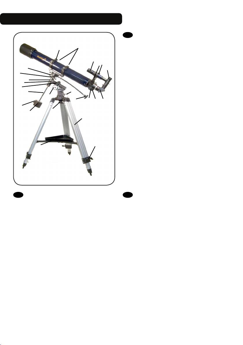
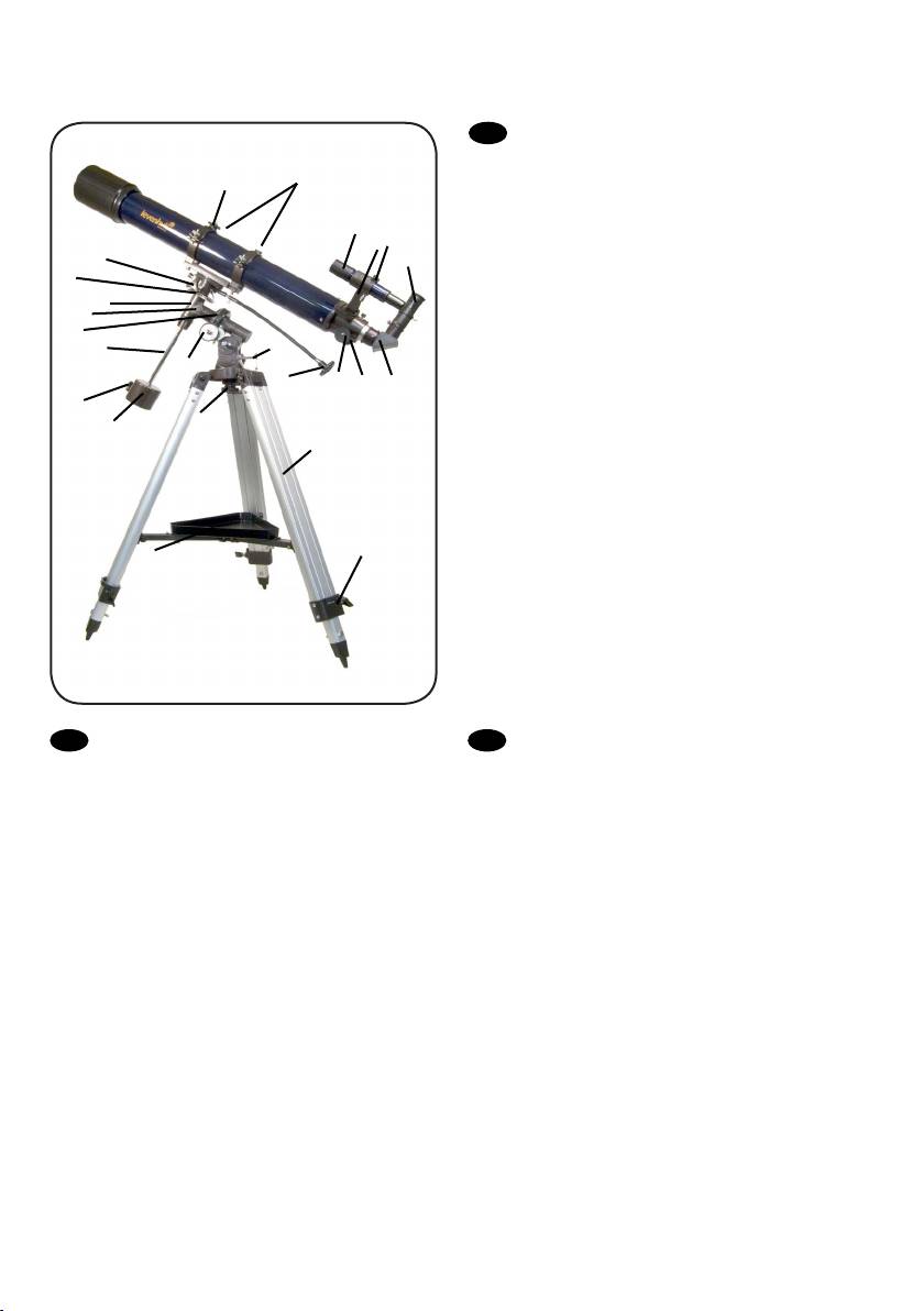
Levenhuk Strike 900 PRO
EN
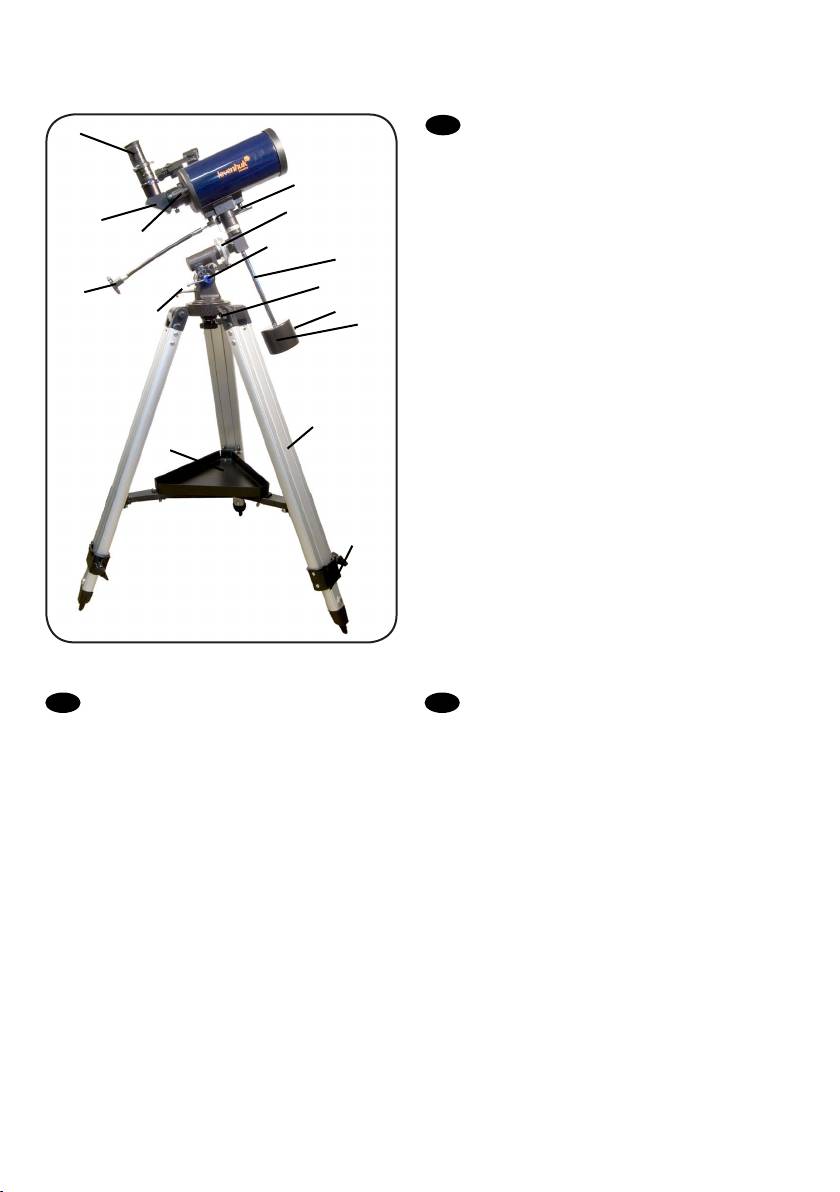
A Piggyback bracket
13
B Finderscope
A
C Finderscope bracket
D Adjustment screws
B
D
E Eyepiece
C
12
F Diagonal mirror
E
11
G Focuser tube
H Focusing knob
4
10
1 Dec. slow-motion control
8
2 Latitude adjustment T-bolt
7
2
3 Azimuth adjustment knob
9
1
4 Latitude lock knob
H
G
F
5 Counterweight
6
6 Counterweight lock screw
3
5
7 Counterweight rod
b
8 R.A. axis scale
9 R.A. slow-motion control
10 R.A. lock knob
11 Dec. axis scale
12 Dec. lock knob
c
13 Ring clamps
a
a Accessory tray
b Tripod leg
c Height adjustment clamp
DE
СZ
A Huckepackschiene
A Piggyback foto držák
B Sucherrohr
B Pointační dalekohled
C Sucherrohr-Halterung
C Konzola pointačního dalekohledu
D Stellschrauben
D Stavěcí šrouby
E Okular
E Okulár
F Diagonalspiegel
F Diagonální zrcátko
G Okularauszug
G Tubus okulárového výtahu
H Fokussierrad
H Zaostřovací šroub
1 Deklinations-Feinabstimmung
1 Ovládání jemného nastavení deklinace
2 Polhöhen-Stellschraube
2 Šroub nastavení zeměpisné šířky
3 Azimut-Stellknopf
3 Šroub nastavení azimutu
4 Polhöhen-Arretierung
4 Aretační šroub zeměpisné šířky
5 Gegengewicht
5 Protiváha
6 Gegengewichts-Halteschraube
6 Aretační šroub protiváhy
7 Gegengewichtsstange
7 Tyč protiváhy
8 Rektaszensionsskala
8 Stupnice osy rektascenze
9 Rektaszensions-Feinabstimmung
9 Ovládání jemného nastavení rektascenze
10 Rektaszensions-Arretierung
10 Aretační šroub osy rektascenze
11 Deklinationsskala
11 Stupnice osy deklinace
12 Deklinations-Arretierung
12 Aretační šroub osy deklinace
13 Rohrschellen
13 Objímky
a Zubehörablage
a Odkládací přihrádka pro příslušenství
b Stativbein
b Noha stativu
c Sicherungsschraube
c Svorka výškového nastavení
1
RU
A Платформа для фотокамеры
13
B Искатель
A
C Крепление искателя
D Юстировочные винты
B
D
E Окуляр
C
12
F Диагональное зеркало
E
11
G Фокусировочный узел
H Ручка фокусировки
4
10
1 Ручка управления тонкими движениями по оси
8
склонения
7
2
2 Регулировочный винт полярной оси по широте
9
1
3 Фиксатор азимута
H
G
F
4 Фиксатор широты места наблюдения
6
5 Противовес
3
5
6 Винт фиксации противовеса
b
7 Ось противовеса
8 Координатный круг прямого восхождения
9 Ручка управления тонкими движениями по оси
прямого восхождения
10 Фиксатор оси прямого восхождения
c
11 Координатный круг склонения
a
12 Фиксатор оси склонения
13 Кольца трубы
a Лоток для аксессуаров
b Ножка треноги
c Фиксатор высоты ножек треноги
PL
UA
A Wspornik typu „piggyback”
A Транспортний кронштейн
B Celownica
B Видошукач
C Wspornik celownicy
C Кронштейн видошукача
D Śruby regulacyjne
D Регулювальні гвинти
E Okular
E Окуляр
F Lustro ukośne
F Діагональне дзеркало
G Tubus ogniskujący
G Труба фокусувача
H Pokrętło ustawiania ostrości
H Ручка фокусування
1 Pokrętło mikroruchów w osi deklinacji
1 Вузол управління повільним рухом схилення
2 Śruba młoteczkowa regulacji w poziomie
2 Т-болт налаштування широти
3 Pokrętło regulacji w poziomie
3 Ручка налаштування азимута
4 Pokrętło blokujące szerokości geogracznej
4 Ручка блокування широти
5 Przeciwwaga
5 Противага
6 Śruba blokująca przeciwwagi
6 Гвинт блокування противаги
7 Pręt przeciwwagi
7 Стержень противаги
8 Skala osi rektascensji
8 Шкала вісі прямого піднесення
9 Pokrętło mikroruchów w osi rektascensji
9 Вузол управління повільним рухом прямого
10 Pokrętło blokujące w osi rektascensji
піднесення
11 Skala osi deklinacji
10 Ручка блокування прямого піднесення
12 Pokrętło blokujące w osi deklinacji
11 Шкала вісі схилення
13 Zaciski pierścienia
12 Ручка блокування схилення
a Tacka na akcesoria
13 Скоби кілець
b Noga statywu
a Лоток для аксесуарів
c Zacisk regulacji wysokości
b Ніжка триноги
c Скоба налаштування висоти
2
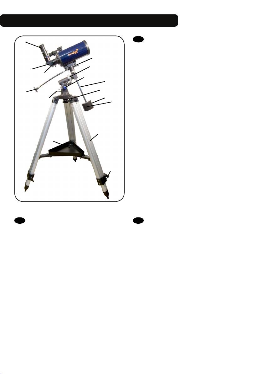
Levenhuk Strike 950 PRO / 1000 PRO
A
EN
A Eyepiece
B Diagonal mirror
9
C Focusing knob
1 R.A. axis scale
1
2 R.A. slow-motion control
B
C
3 Latitude adjustment T-bolt
8
4 Azimuth adjustment knob
7
5 Counterweight
4
6 Counterweight lock screw
2
6
7 Counterweight rod
3
5
8 Dec. lock knob
9 Dec. axis scale
a Accessory tray
b Tripod leg
c Height adjustment clamp
b
a
c
DE
СZ
A Okular
A Okulár
B Diagonalspiegel
B Diagonální zrcátko
C Fokussierrad
C Zaostřovací šroub
1 Rektaszensionsskala
1 Stupnice osy rektascenze
2 Rektaszensions-Feinabstimmung
2 Ovládání jemného nastavení rektascenze
3 Polhöhen-Stellschraube
3 šroub nastavení zeměpisné šířky
4 Azimut-Stellknopf
4 Šroub nastavení azimutu
5 Gegengewicht
5 Protiváha
6 Gegengewichts-Halteschraube
6 Aretační šroub protiváhy
7 Gegengewichtsstange
7 Tyč protiváhy
8 Deklinations-Arretierung
8 Aretační šroub osy deklinace
9 Deklinationsskala
9 Stupnice osy deklinace
a Zubehörablage
a Odkládací přihrádka pro příslušenství
b Stativbein
b Noha stativu
c Sicherungsschraube
c Svorka výškového nastavení
3
A
RU
A Окуляр
B Диагональное зеркало
9
C Ручка фокусировки
1 Координатный круг прямого восхождения
1
B
2 Ручка управления тонкими движениями по оси
C
склонения
8
3 Фиксатор широты места наблюдения
7
4 Фиксатор азимута
4
2
5 Противовес
6
6 Винт фиксации противовеса
3
5
7 Ось противовеса
8 Фиксатор оси склонения
9 Координатный круг склонения
a Лоток для аксессуаров
b Ножка треноги
c Фиксатор высоты ножек треноги
b
a
c
PL
UA
A Okular
A Окуляр
B Lustro ukośne
B Діагональне дзеркало
C Pokrętło ustawiania ostrości
C Ручка фокусування
1 Skala osi rektascensji
1 Шкала вісі прямого піднесення
2 Pokrętło mikroruchów w osi rektascensji
2 Вузол управління повільним рухом прямого
3 Śruba młoteczkowa regulacji w poziomie
піднесення
4 Pokrętło regulacji w poziomie
3 Т-болт налаштування широти
5 Przeciwwaga
4 Ручка налаштування азимута
6 Śruba blokująca przeciwwagi
5 Противага
7 Pręt przeciwwagi
6 Гвинт блокування противаги
8 Pokrętło blokujące w osi deklinacji
7 Стержень противаги
9 Skala osi deklinacji
8 Ручка блокування схилення
a Tacka na akcesoria
9 Шкала вісі схилення
b Noga statywu
a Лоток для аксесуарів
c Zacisk regulacji wysokości
b Ніжка триноги
c Скоба налаштування висоти
4
1
2
33
34
5
35
EN
Altitude adjustment knob
1
4
СZ
Šroub nastavení elevace
3
DE
Höhenwinkel-Stellknopf
PL
2
Pokrętło regulacji w pionie
RU
Винт регулировки высоты
UA
Гвинт налаштування висоти
EN
Brightness control
1
2
СZ
Regulátor jasu
DE
Helligkeitsregler
PL
Pokrętło regulacji jasności
RU
Регулятор яркости
UA
Вузол управління яскравістю
5
36
EN
Azimuth adjustment knob
EN
Scope
EN
Battery compartment cover
3
4
5
СZ
Šroub nastavení azimutu
СZ
Hledáček
СZ
Kryt prostoru pro baterii
DE
Azimut-Stellknopf
DE
Visier
DE
Batteriefachdeckel
PL
Pokrętło regulacji w poziomie
PL
Szukacz
PL
Pokrywa komory baterii
RU
Винт регулировки азимута
RU
Искатель
RU
Крышка батарейного отсека
UA
Гвинт налаштування азимута
UA
Шукач
UA
Кришка відділення батарей
6
5
1
4
7
2
6
8
7
3
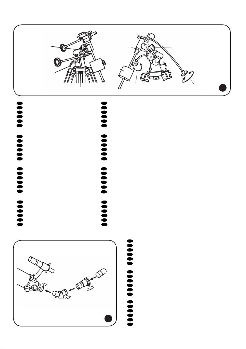
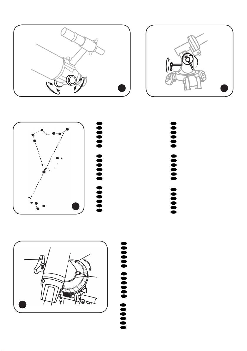
EN
R.A. adjustment
EN
Dec. adjustment
1
5
СZ
Nastavení rektascenze
СZ
Nastavení deklinace
DE
Rektaszensionseinstellung
DE
Deklinationseinstellung
PL
Regulacja w osi rektascensji
PL
Regulacja w osi deklinacji
RU
Фиксатор прямого восхождения
RU
Фиксатор оси склонения
UA
Налаштування прямого сходження
UA
Налаштування схилення
EN
Altitude adjustment (up-down)
EN
R.A. ne adjustment
2
6
СZ
Nastavení elevace (nahoru-dolů)
СZ
Jemné nastavení rektascenze
DE
Höhenwinkeleinstellung (auf/ab)
DE
Rektaszensions-Feineinstellung
PL
Regulacji w pionie (góra – dół)
PL
Dokładna regulacja w osi rektascensji
RU
Регулировка высоты (вверх-вниз)
RU
Тонкая регулировка прямого восхождения
UA
Налаштування висоти (вверх-вниз)
UA
Точне налаштування прямого сходження
EN
Azimuth adjustment (left-right)
EN
R.A. adjustment
3
7
СZ
Nastavení azimutu (doleva-doprava)
СZ
Nastavení rektascenze
DE
Azimuteinstellung (links/rechts)
DE
Rektaszensionseinstellung
PL
Regulacji w poziomie (lewo – prawo)
PL
Regulacja w osi rektascensji
RU
Регулировка азимута (влево-вправо)
RU
Фиксатор прямого восхождения
UA
Налаштування азимуту (вліво-вправо)
UA
Налаштування прямого сходження
EN
R.A. scale
EN
Dec. ne adjustment
4
8
СZ
Stupnice rektascenze
СZ
Jemné nastavení deklinace
DE
Rektaszensionsskala
DE
Deklinations-Feineinstellung
PL
Dokładna regulacja w osi deklinacji
PL
Skala osi rektascensji
RU
Шкала прямого восхождения
RU
Тонкая регулировка склонения
UA
Шкала прямого сходження
UA
Точне налаштування схилення
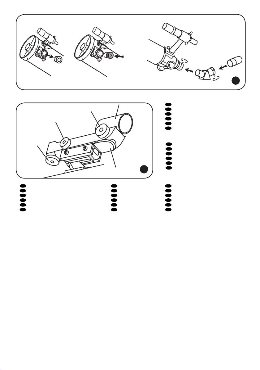
EN
Diagonal mirror
1
СZ
Diagonální zrcátko
DE
Diagonalspiegel
PL
Lustro ukośne
RU
Диагональное зеркало
UA
Діагональне дзеркало
EN
Barlow lens
2
СZ
Barlowova čočka
3
DE
Barlow-Linse
PL
Soczewka Barlowa
RU
Линза Барлоу
UA
2
Лінза Барлов
EN
Eyepiece
1
3
СZ
Okulár
DE
Okular
PL
Okular
8
RU
Окуляр
UA
Окуляр
7
9
10
EN
Big Dipper
EN
NCP
1
4
1
СZ
Velká medvědice
СZ
NCP
6
DE
Großer Wagen
DE
NHP
PL
Wielka Niedźwiedzica
PL
NCP
RU
Большая Медведица
RU
СНП
UA
Велика Ведмедиця
UA
NCP
2
EN
Little Dipper
EN
Cassiopeia
2
5
СZ
Malý medvěd
СZ
Kasiopeja
DE
Kleiner Wagen
DE
Kassiopeia
PL
Mała Niedźwiedzica
PL
Kasjopeja
4
3
RU
Малая Медведица
RU
Кассиопея
UA
Мала Ведмедиця
UA
Кассіопея
EN
Polaris
3
EN
β Crucis
6
СZ
Polárka
СZ
β Crucis
DE
Polarstern
DE
β Crucis
5
PL
Gwiazdą Polarną
PL
β Crucis
RU
11
Полярная звезда
RU
β Crucis
UA
Полярна зірка
UA
β Хреста
EN
R.A. lock knob
1
СZ
Aretační šroub osy rektascenze
DE
Rektaszensions-Arretierung
2
PL
Pokrętło blokujące w osi rektascenji
1
RU
Фиксатор оси прямого восхождения
UA
Ручка блокування прямого піднесення
EN
R.A. settling circle
2
3
СZ
Kruh pro nastavení osy rektascenze
DE
Rektaszensions-Teilkreis
PL
Tarcza ze współrzędnymi rektascensji
RU
Установочный круг прямого восхождения
UA
Круг налаштування прямого піднесення
12
EN
Arrow
3
СZ
Šipka
DE
Pfeil
PL
Strzałka
RU
Стрелка
UA
Стрілка
8
1
12
10
8
6
13
3
2
5
9
4
11
13
7
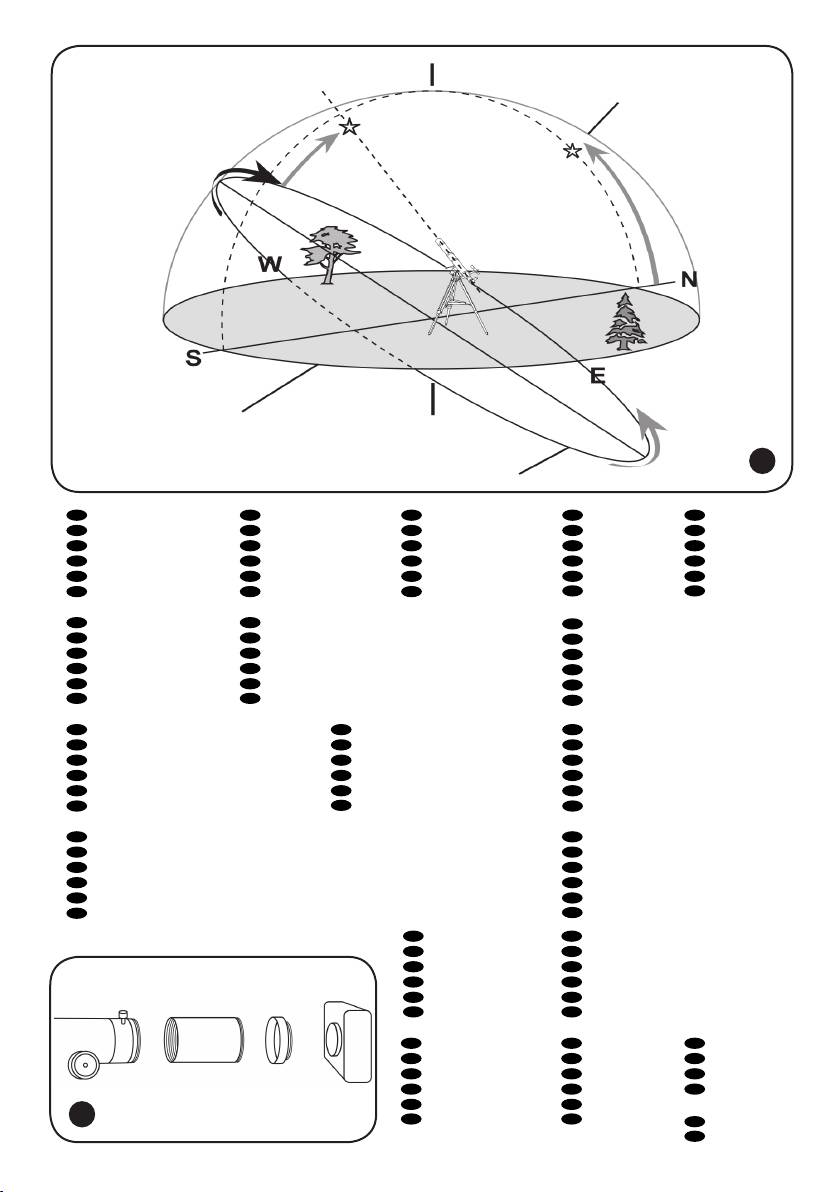
EN
Zenith
EN
Meridian line
EN
Latitude
EN
Nadir
EN
N E S W
1
2
3
4
5
СZ
Zenit
СZ
Poledník
СZ
Zeměpisná šířka
СZ
Nadir
СZ
S V J Z
DE
Zenit
DE
Meridianlinie
DE
Breite
DE
Nadir
DE
N O S W
PL
Zenit
PL
Południk niebieski
PL
Szerokość
PL
Nadir
PL
N E S W
RU
Зенит
RU
Линия меридиана
RU
Широта
RU
Надир
RU
С В Ю З
UA
Зеніт
UA
Лінія меридіану
UA
Широта
UA
Надир
UA
ПВН С ПВД З
EN
Right Ascension
EN
Plane of Celestial Equator
EN
Polaris
6
7
8
СZ
Rektascenze
СZ
Rovina nebeského rovníku
СZ
Polárka
DE
Rektaszension
DE
Himmelsäquatorebene
DE
Polarstern
PL
Rektascensja
PL
Równik niebieski
PL
Gwiazdą Polarną
RU
Прямое восхождение
RU
Плоскость небесного экватора
RU
Полярная звезда
UA
Пряме піднесення
UA
Площина небесного екватора
UA
Полярна зірка
EN
Plane of local horizon
EN
Object you are viewing
EN
Apparent movement of stars
9
10
11
СZ
Rovina lokálního horizontu
СZ
Pozorovaný objekt
СZ
Zdánlivý pohyb hvězd
DE
Lokale Horizontebene
DE
Betrachtetes Objekt
DE
Scheinbare Sternbewegung
PL
Płaszczyzna horyzontu
PL
Obserwowany obiekt
PL
Pozorny ruch gwiazd
RU
Плоскость местного горизонта
RU
Наблюдаемый объект
RU
Видимое движение звезд
UA
Площина місцевого горизонту
UA
Об’єкт, який
UA
Видиме переміщення зірок
спостерігається
EN
Mount aligned on North Celestial Pole
EN
Declination
12
13
СZ
Montáž nastavená na severní nebeský pól
СZ
Deklinace
DE
Am nördlichen Himmelspol ausgerichtete Montierung
DE
Deklination
PL
Montaż ustawiony na północny biegun niebieski
PL
Deklinacja
RU
Монтировка выровнена на Северный небесный полюс
RU
Склонение
UA
Кріплення, вирівняне на Північний небесний полюс
UA
Схилення
EN
Focuser
EN
Extender
1
3
СZ
Okulárový výtah
СZ
Nástavec
DE
Okularauszug
DE
Verlängerung
PL
Tubus ogniskujący
PL
Przedłużenie
RU
Фокусер
RU
Экстендер (удлинитель фокуса)
UA
Фокусувач
UA
Розширювач
1
EN
Eyepiece holder
EN
T-adapter
EN
Camera
2
4
5
СZ
Držák okuláru
СZ
T-adaptér
СZ
Fotoaparát
DE
Okularhalterung
DE
T-Adapter
DE
Kamera
2 3 4
PL
Wyciąg okularowy
PL
T-adapter
PL
Aparat
5
RU
Держатель окуляра
RU
Т-адаптер
fotograczny
14
UA
Держак окуляра
UA
Т-подібний
RU
Камера
адаптер
UA
Фотокамера
9
