YUKON EXTEND LRS-1000: External appearance and controls Battery installation
External appearance and controls Battery installation: YUKON EXTEND LRS-1000
Table of contents
- SPECIFICATIONS PACKAGE CONTENTS
- DESCRIPTION Safety rules
- External appearance and controls Battery installation
- USING THE RANGEFINDER Measuring distance: Scan mode Measuring speed
- Switching measuring units PECULIARITIES OF OPERATION
- MAINTENANCE STORAGE
- TROUBLESHOOTING
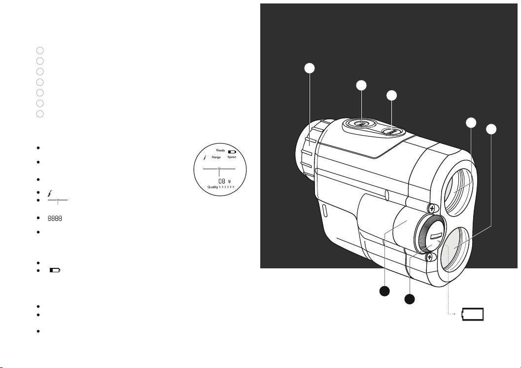
External appearance and controls
1
Lens/Emitter
2
Signal receiver
3
3
Eyepiece
4
“ON” Switch
4
5
“Mode” Switch
5
6
Battery compartment
7
Battery cap
1
2
Reading the LCD display
“Ready” – indicates that the unit is ready for
use.
“Range” – range measurement function is
activated.
“Speed” – speed measurement function is
activated.
“ ” – indicates laser signal transmission.
“ ” – target indicator. Aiming mark –
centre this over a target.
“ ” – distance is shown in four digits. In
case of error four dashes show up “----”.
“KM/h” – indicates speed (kilometers per
hour), “M/S” (meters per second). Indications
“M” (meter) and “Y” (yard) are used in range
measurement mode.
“Quality >>>>> ” – target quality indicator.
“ ” – low battery indicator.
Battery installation
6
7
Unscrew the battery cap counterclockwise (7).
Insert a CR2 battery observing polarity shown in the battery
+
CR2/3V
-
compartment (see diagram on page 2).
Replace the battery cap, screwing it on clockwise. Do not
overtighten.
4
45
