Tripp Lite OMNIVSINT800: instruction
Class: Tools, power tools and power equipment
Type:
Manual for Tripp Lite OMNIVSINT800

Owner’s Manual
Models: OMNIVSINT800,
OMNIVSINT1000, OMNIVSINT1500XL*
230V Input, Line-Interactive UPS Systems (Tower Configuration)
* Extended runtime options
Important Safety Instructions
2
Quick Installation
3
Basic Operation
5
Storage & Service
8
Specifications
8
Español
9
Français
17
Póññêè
é
25
1111 W. 35th Street Chicago, IL 60609 USA
Customer Support: (773) 869-1234 • www.tripplite.com
©
Copyright
2004 Tripp Lite. All rights reserved.
200404081 932242 OmniVSINT800_1000_ 1500XL Owners Manual .qxd 6/8/2004 11:36 AM Page 1

Important Safety Instructions
SAVE THESE INSTRUCTIONS
This manual contains instructions and warnings that should be followed during the
installation, operation and storage of all Tripp Lite UPS Systems. Failure to heed these
warnings will void your warranty.
UPS Location Warnings
• Install your UPS indoors, away from excess moisture or heat, dust or direct sunlight.
• For best performance, keep the indoor temperature between between 32º F and 104º F
(0º C and 40º C).
• Leave adequate space around all sides of the UPS for proper ventilation.
UPS Connection Warnings
• Connect your UPS directly to a properly grounded AC power outlet. Do not plug the UPS
into itself; this will damage the UPS.
• Do not modify the UPS’s plug, and do not use an adapter that would eliminate the UPS’s
ground connection.
• Do not use extension cords to connect the UPS to an AC outlet. Your warranty will be
voided if anything other than Tripp Lite surge suppressors are used to connect your UPS
to an outlet.
• If the UPS receives power from a motor-powered AC generator, the generator must
provide clean, filtered, computer-grade output.
Equipment Connection Warnings
• Do not use Tripp Lite UPS Systems for life-support applications in which a malfunction
or failure of a Tripp Lite UPS System could cause failure or significantly alter the
performance of a life-support device.
• Do not connect surge suppressors or extension cords to the output of your UPS.
Battery Warnings
Batteries can present a risk of electrical shock and burn from high short-circuit current.
Observe proper precautions. Do not dispose of the batteries in a fire. Do not open the UPS
or batteries. Do not short or bridge the battery terminals with any object. Unplug and turn
off the UPS before performing battery replacement. Use tools with insulated handles.
There are no user-serviceable parts inside the UPS. Battery replacement should be performed
only by authorized service personnel using the same number and type of batteries (sealed
Lead-Acid).The batteries are recyclable. Refer to your local codes for disposal requirements
or in the USA only call 1-800-SAV-LEAD or 1-800-8-BATTERY (1-800-8-228-8379) or
visit www.rbrc.com for recycling information. Tripp Lite offers a complete line of UPS
System Replacement Battery Cartridges (R.B.C.).Visit Tripp Lite on the Web at
www.tripplite.com to locate the specific replacement battery for your UPS.
2
200404081 932242 OmniVSINT800_1000_ 1500XL Owners Manual .qxd 6/8/2004 11:36 AM Page 2
Quick Installation
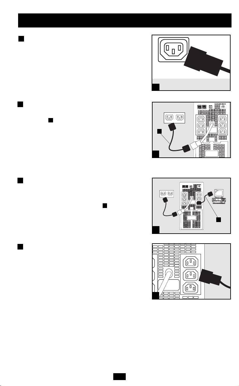
1
Unplug the computer’s power
cord from both AC outlet and
the computer’s AC input.
2
Insert the female plug of the
computer’s cord into the UPS’s AC
input. Insert the male plug of the
A
computer’s cord into AC outlet.
NOTE! After you plug the UPS into a live AC outlet, the UPS will
turn ON automatically. See “ON/OFF/STANDBY” Button
description in the Basic Operation section if you want to place the
UPS in any mode other than ON.
3
Using one of the jumper cords
supplied with the UPS, insert
the cord’s female plug into
computer’s AC input . Insert
B
the cord’s male plug into any of
UPS’s female output receptacles.
4
Plug additional equipment into
the UPS.*
Use one of the additional jumper cords supplied with
the UPS, or order additional jumper cords from
Tripp Lite. Call (773) 869-1234; order part # P004-006.
* Your UPS is designed to support only computer equipment. You
will overload the UPS if the total VA ratings for all the equipment you
connect exceeds the UPS’s output capacity (see Specifications). To
find your equipment's VA ratings, look on their nameplates. If the
equipment is listed in amps, multiply the number of amps by 230 to
determine VA. (Example: 1 amp × 230 = 230 VA). If you are unsure if
you have overloaded the UPS’s outlets, see “OUTPUT LOAD
LEVEL” LED description.
3
NORM DELAY
NORM DELAY
1
IEC320-C14 plug shown
A
2
Shown: OMNIVSINT1000
B
3
Shown: OMNIVSINT1000
4
Shown: OMNIVSINT1000
200404081 932242 OmniVSINT800_1000_ 1500XL Owners Manual .qxd 6/8/2004 11:36 AM Page 3
Quick Installation
optional
These connections are optional. Your UPS will function properly without these connections.
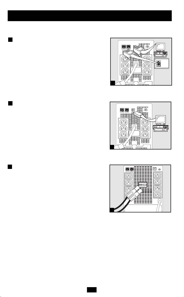
1
Phone Line or Phone/Network
Line Surge Suppression
(Select models only)
Your UPS has jacks which protect against
surges on a phone line or data line (depending
on model). Using telephone or network cords
connect your wall jack to the UPS jack marked
“IN.” Connect your equipment to the UPS jack
marked “OUT.” Make sure the equipment you
connect to the UPS’s jacks is also protected
against surges on the AC line.
2
USB Communications
Use any USB cable to connect the USB port of
your computer to the USB port of your UPS.
Download the PowerAlert UPS monitoring
software program appropriate for your operat-
ing system from www.tripplite.com and install
it on your computer.
External Battery Connection
(Select models only)
All UPS models come with a robust internal
battery system; select models feature connectors
that accept an optional external battery pack
(sold separately from Tripp Lite*) to provide
additional runtime. Adding an external battery
will increase recharge time as well as runtime.
See battery pack owner's manual for complete
installation instructions. Make sure cables are
fully inserted into their connectors. Small
sparks may result during battery connection; this
is normal. Do not connect or disconnect battery
pack when the UPS is running on battery power.
*See Specifications section for battery pack available for
your specific UPS model.
4
NORM DELAY
1
NORM DELAY
2
NORM DELAY
Shown: OMNIVSINT1000
Shown: OMNIVSINT1000
3
3
Shown: OMNIVSINT1500XL
200404081 932242 OmniVSINT800_1000_ 1500XL Owners Manual .qxd 6/8/2004 11:36 AM Page 4

Basic Operation
Buttons
“ON/OFF/STANDBY” Button
• To turn the UPS ON: if utility power is present, the UPS will turn
ON automatically. If utility power is absent, you can “cold-start” the
UPS (i.e.: turn it ON and supply power from its batteries*) by pressing
and holding the ON/OFF/STANDBY button for one second.**
• To turn the UPS OFF: first, unplug the UPS from the wall outlet;
then press and hold the ON/OFF/STANDBY button for one
second.** The UPS will be completely “OFF” (deactivated).
• To place the UPS in “Charge-Only” Mode: this mode enables battery
charging, but disables battery backup. WARNING: when the UPS is in
this mode, it will not provide battery backup during a blackout or
brownout. This mode is only recommended for use in areas that
experience frequent blackout/brownout conditions and when connected
equipment is not in use. Press and hold the ON/OFF/STANDBY
button for four seconds to place the UPS in this mode.** Press and
hold the ON/OFF/STANDBY button for one second** to take the
UPS out of this mode.
*If fully charged. **The alarm will beep once briefly after one second has passed (and
will beep continuously after four seconds have passed which signals transition to the
“Charge-Only” Mode).
“MUTE/TEST” Button
To Silence (or “Mute”) UPS Alarms: briefly press and release the
MUTE/TEST button. Note: continuous alarms (warning you to imme-
diately shut down connected equipment) cannot be silenced.
To Run a Self-Test: with your UPS plugged in and turned ON, press
and hold the MUTE/TEST button for two seconds. Continue holding
the button until the alarm beeps several times and the UPS performs
a self-test. See “Results of a Self-Test” below. Note: you can leave
connected equipment on during a self-test. Your UPS, however, will
not perform a self-test if you have placed it in “Charge-Only” mode
(see “ON/OFF/STANDBY” Button description).
CAUTION! Do not unplug your UPS to test its batteries. This will
remove safe electrical grounding and may introduce a damaging
surge into your network connections.
Results of a Self-Test: The test will last approximately 10 seconds
as the UPS switches to battery to test its load capacity and
charge.
• If the “OVERLOAD” LED remains lit and the alarm continues to
sound after the test, the battery-supported outlets are overloaded.
To clear the overload, unplug some of your equipment from the bat-
tery- supported outlets and run the self-test repeatedly until the “OVER-
LOAD” LED is no longer lit and the alarm is no longer sounding.
CAUTION! Any overload that is not corrected by the user
immediately following a self-test may cause the UPS to shut
down and cease supplying output power in the event of a
blackout or brownout.
• If the “REPLACE BATTERY” LED remains lit and the alarm
continues to sound after the test, the UPS batteries need to be
recharged or replaced. Allow the UPS to recharge continuously
for 2-4 hours, and repeat the self-test. If the LED continues to
flash, contact Tripp Lite for service. If your UPS requires battery
replacement, visit www.tripplite.com to locate the specific
Tripp Lite replacement battery for your UPS.
5
200404081 932242 OmniVSINT800_1000_ 1500XL Owners Manual .qxd 6/8/2004 11:36 AM Page 5
All Indicator Light descriptions apply when the UPS is plugged into an AC outlet and turned on.
“LINE POWER” LED: this green LED lights continuously to indicate
that the UPS is ON and supplying your equipment with AC power from a
utility source. The LED flashes to remind you that you have used the
ON/OFF/STANDBY button to place the UPS in “Charge-Only” mode.
“BATTERY POWER” LED: this yellow LED lights continuously and an
alarm sounds (4 short beeps followed by a pause) to indicate the UPS is oper-
ating from its internal batteries. During a prolonged brownout or blackout,
this LED and the “REPLACE BATTERY” LED will light continuously and
an alarm will sound continuously to indicate the UPS's batteries are nearly out
of power; you should save files and shut down your equipment immediately.
“REPLACE BATTERY” LED: this red LED lights continuously and an
alarm sounds after a self-test to indicate the UPS batteries need to be
recharged or replaced. Allow the UPS to recharge continuously for at least
4 hours, and repeat the self-test. If the LED continues to flash, contact Tripp Lite
for service. If your UPS requires battery replacement, visit
www.tripplite.com/support/battery/index.cfm to locate the specific Tripp Lite
replacement battery for your UPS.
“OVERLOAD” LED: this red LED lights continuously and an alarm
sounds after a self-test to indicate the battery-supported outlets are overloaded.
To clear the overload, unplug some of your equipment from the battery-
supported outlets and run the self-test repeatedly until the LED is no longer
lit and the alarm is no longer sounding.
CAUTION! Any overload that is not corrected by the user immediately
following a self-test may cause the UPS to shut down and cease supplying
output power in the event of a blackout or brownout.
“VOLTAGE CORRECTION” LED (select models only): Although all
models automatically correct incoming voltage, select models include an
LED which lights green whenever the UPS is performing this function.
The UPS will also click gently. These are normal, automatic operations of
your UPS, and no action is required on your part.
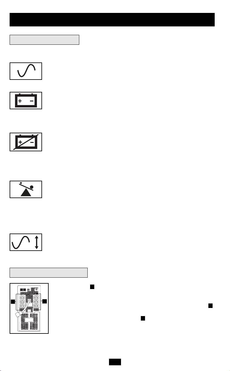
AC Outlets: the outlets will provide battery backup and surge protection;
A
plug your computer, monitor, printer and other critical devices here. Your
UPS is designed to only support computer equipment. You will overload
the UPS if the total VA ratings for all the equipment you connect to the
A
outlets exceeds the UPS’s output capacity (see Specifications). If you are
unsure if you have overloaded the outlets, run a self-test (see
A
“MUTE/TEST” Button description).
6
NORM DELAY
Basic Operation
continued
Indicator Lights
Other UPS Features
A
A
Shown: OMNIVSINT1000
200404081 932242 OmniVSINT800_1000_ 1500XL Owners Manual .qxd 6/8/2004 11:36 AM Page 6
Basic Operation
continued
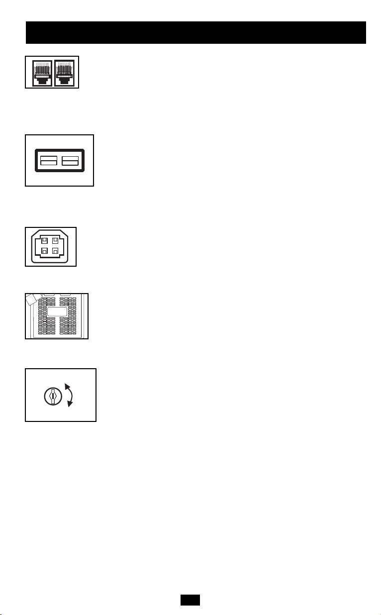
Telephone/Network Protection Jacks (select models): These jacks
protect your equipment against surges over a telephone or data line.
Your UPS has either jacks which can be used with both phone and
data lines, or jacks which can be used with phone lines only. See
Specifications to determine what kind of jacks your UPS has.
Connecting your equipment to these jacks is optional. Your UPS will
work properly without this connection.
External Battery Pack Connection (select models): Check to
ensure that the external batteries you are connecting match the voltage
listed on your UPS's battery connector. Plug the battery connection
cable (attached to the battery pack) into the UPS’s External Battery
Connector. Since your UPS has internal batteries, external batteries
are only needed to extend runtime. Adding external batteries will
increase recharge time as well as runtime. Make sure that the end of
the cable is fully inserted into the UPS connector. Several small
sparks may result during battery connection; this is normal.
USB Port: The USB port connects your UPS to any USB workstation
or server. Using this port, your UPS can communicate “line-fail” and
“low-battery” status to your computer. Use with Tripp Lite software
and any USB cable to automatically save open files and shut down
equipment during a blackout. Contact Tripp Lite Customer Support or
consult your power protection software manual for more information.
Battery Replacement Door: Battery Replacement Door: Under nor-
mal conditions, the original battery in your UPS will last several
years. Battery replacement should be performed only by qualified
service personnel. Refer to “Battery Warnings” in the Safety section.
Should your UPS require battery replacement, visit Tripp Lite on the
Web at www.tripplite.com to locate the specific replacement battery
for your UPS.
Power Sensitivity Adjustment: This dial is normally set fully counter-
clockwise, which enables the UPS to provide maximum protection
against waveform distortions in its AC input. When such distortion
occurs, the UPS will normally switch to providing PWM sine wave
power from its battery reserves for as long as the distortion is pres-
ent. In areas with poor utility power or where the UPS’s input power
comes from a backup generator, chronic waveform distortion could
cause the UPS to switch to battery too frequently, draining its battery
reserves. You may be able to reduce how often your UPS switches to
battery due to moderate waveform distortion by experimenting with
different settings for this dial. As the dial is turned clockwise, the
UPS becomes more tolerant of variations in its input power’s AC wave-
form. NOTE: The further the dial is adjusted clockwise, the greater
the degree of waveform distortion the UPS will allow to pass to con-
nected equipment. When experimenting with different settings for
this dial, operate connected equipment in a safe test mode so that the
effect on the equipment of any waveform distortions in the UPS’s
output can be evaluated without disrupting critical operations.
7
200404081 932242 OmniVSINT800_1000_ 1500XL Owners Manual .qxd 6/8/2004 11:36 AM Page 7
NORM
DELAY

Storage & Service
Storage
All connected equipment should be turned off, then disconnected from the UPS to avoid battery
drain. Unplug the UPS from the wall outlet; then press and hold the ON/OFF/STANDBY button for
one second. The UPS will be completely “OFF” (deactivated). Your UPS is now ready for stor-
age. If you plan on storing your UPS for an extended period of time, fully recharge the UPS bat-
teries once every three months by plugging the UPS into a live AC outlet and letting the UPS
charge for up to 4 hours. If you leave your UPS batteries discharged for an extended period of
time, they will suffer a permanent loss of capacity.
Service
Before returning your UPS for service, follow these steps:
1. Review the installation and operation instructions in this manual to ensure that the service
problem does not originate from a misreading of the instructions. Also, check that the UPS
System’s circuit breaker(s) are not tripped. This is the most common cause of service
inquiries which can be easily remedied by following the resetting instructions in this manual.
2. If the problem continues, do not contact or return the UPS to the dealer. Instead, call Tripp Lite
at (773) 869-1233. A service technician will ask for the UPS's model number, serial number
and purchase date and will attempt to correct the problem over the phone.
3. If the problem requires service, the technician will issue you a Returned Material
Authorization (RMA) number, which is required for service. If you require packaging, the
technician can arrange to send you proper packaging. Securely pack the UPS to avoid damage
during shipping. Do not use Styrofoam beads for packaging. Any damages (direct, indirect,
special, incidental or consequential) to the UPS incurred during shipment to Tripp Lite or
an authorized Tripp Lite service center is not covered under warranty. UPS Systems shipped
to Tripp Lite or an authorized Tripp Lite service center must have transportation charges
prepaid. Mark the RMA number on the outside of the package. If the UPS System is within
the 2-year warranty period, enclose a copy of your sales receipt. Return the UPS for service
using an insured carrier to the address given to you by the Tripp Lite service technician.
Specifications
Tripp Lite has a policy of continuous improvement. Specifications are subject to change without notice.
Model: OMNIVSINT800 OMNIVSINT1000 OMNIVSINT1500XL
Series: AGOM4901 AGOM4901 AGOM4775
Input Voltage/Frequency: 230VAC/50/60 Hz 230VAC/50/60 Hz 230VAC/50/60 Hz
Output Capacity (VA/Watts): 800/475 1000/500 1500/940
Battery Runtime (Half Load/Full Load) Minutes: 19/6 18/7 14/5+
Battery Recharge Time: 2-4 hrs. 2-4 hrs. 2-4 hrs.
Approvals: CE, GOST, SASO, IRAM CE, GOST, SASO, IRAM CE, GOST, SASO, IRAM, TUVGS
Tel/Fax/Data Protection: 1-line tel/DSL 1-line tel/DSL 1-line tel/DSL/Ethernet
Output Voltage Line Mode (230VAC); Output Voltage On Battery (230VAC). Output Waveform Line Mode (filtered sinewave); Output Waveform Battery Mode (PWM sine wave); AC Surge
Suppression (exceeds IEEE 587 Cat. A & B standards); AC Noise Attenuation (>40 dB at 1MHz); AC Protection Modes (H to N).
Battery runtime for OMNIVSINT1500XL can be extended with the addition of a single optional Tripp Lite External Battery Pack which is not expandable (model # BP24V14, sold separately).
An External Battery will increase both the battery runtime and the battery recharge time.
Note on Labeling
Two symbols are used on the label.
V~ : AC Voltage
V : DC Voltage
8
200404081 932242 OmniVSINT800_1000_ 1500XL Owners Manual .qxd 6/8/2004 11:36 AM Page 8
Table of contents
- Models: OMNIVSINT800, OMNIVSINT1000, OMNIVSINT1500XL*
- Modelos: OMNIVSINT800, OMNIVSINT1000, OMNIVSINT1500XL*
- Models: OMNIVSINT800, OMNIVSINT1000, OMNIVSINT1500XL*
- Mîäåëè: OMNIVSINT800, OMNIVSINT1000, OMNIVSINT1500XL*
