SilverStone F1 ST55GF installation: instruction
Class: Computer equipment, hardware, accessories
Type: Power Supplier/Provider
Manual for SilverStone F1 ST55GF installation

ower suppl multilanguage manual
P
y
ENGLISH
1 - 6
DEUTSCH
7 - 12
FRANCAIS
13 - 18
ITALIANO
19 - 24
ESPANOL
25 - 30
31 - 36
37 - 42
䚐ạ㛨
43 - 48
49 - 54
55 - 60
䚐ạ㛨
Index
㋤ʑᄽ
ⅺʑᄽ
ENGLISH
PSU product manual
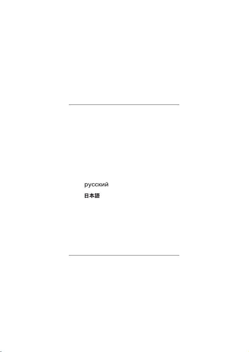
Power supply installation (For new system assembly)
1
4
Please ensure power supply is not
Connect ATX 20-pin/EPS 24-pin power
connected to AC power cable.
cable to the motherboard's
corresponding connector.
2
5
Please switch to the correct voltage
Connect ATX +12V 4-pin / EPS +12V
for your location. ( For non-PFC power
8-pin power cable to the motherboard's
supplies only)Note: Power supplies
corresponding connector.
with PFC function can adjust input
power voltage automatically without
user intervention.
3
6
Place the power supply in the chassis location
Connect PCI-E 6-pin/8-pin power cable to
designated for power supply and secure it.
PCI-Express video card's corresponding
( Please refer to your chassis manual)
connector. (If necessary)
1
ENGLISH
PSU product manual
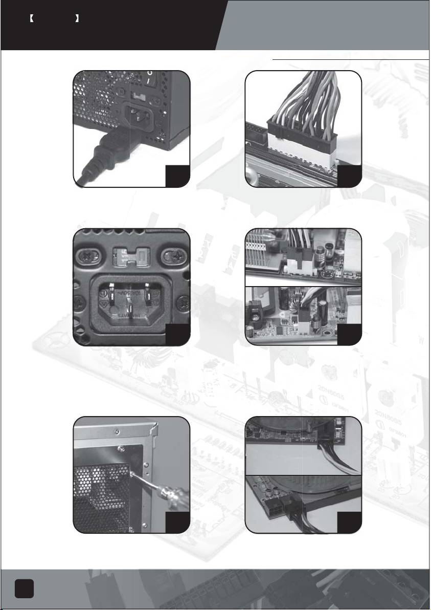
Power supply installation (for new system assembly)
7
10
Connect SATA power cables to
Connect small 4-pin power cable to
SATA hard drives or devices.
floppy drives or other compatible
devices
8
11
Connect 4-pin peripheral power
Reinstall chassis's cover, and secure
cables to IDE hard drives, optical
it. ( Please refer to the installation
drives or other devices.
of chassis)
9
12
Connect 4-pin peripheral power cables
Connect AC power cable to the power
to fans utilizing the peripheral connectors.
supply. (Caution: please do not use
(DC +12V variety)
extension socket, if using extension socket is
necessary, avoid combined usage with
other higher powered household appliances
such as TV, audio amplifier, etc…)
2
ENGLISH
PSU product manual
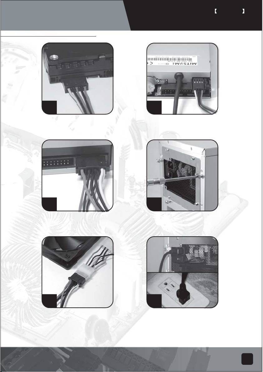
Power supply installation (For new system assembly)
Turn on the power supply by switching to "I" (I/O) mode.
Caution: The power supply is on standby now. System
on and off is controlled by the motherboard.
(Please refer to the motherboard manual)
13
Power supply installation (For replacement)
1
3
After turning off the system, switch the
Remove all power supply cables
power supply to "O" position to disable
connected to the motherboard, video
system standby and make sure the system
card, hard drive and other device.
is no longer drawing any power.
2
4
Remove AC power cable from the
Remove power supply from the chassis.
power supply.
(Please refer to your chassis's installation manual.)
5. Please refer now to Step 1 of "Power supply
installation (for new system assembly)"
3
ENGLISH
PSU product manual
Power supply usage notes and caution
1. The power supply includes dangerous high voltage; please do not open the power supply in
any condition. Once the power supply enclosure is opened, it will no longer be covered
under warranty.
2. Please use power supply in safe and dry surroundings.
3. Please do not obstruct, insert, or put anything into power supply's vents and any other
openings.
4. The AC cable included with the power supply has been stringently examined by the factory
for defects and quality so please use only the AC cable supplied with your power supply.
AC power cable manufactured by a third party may produce incompatible results and
possibly cause damage to your system or power supply.
5. This product is designed for indoor use only.
Troubleshooting
If your power supply is not operating properly, please refer to the following steps:
1. Please make sure the voltage switch is in the correct mode for use in your location
(115V or 230V). (For power supplies without PFC function only)
2. Please ensure AC power cable is connect to the power supply.
3. Please make sure power supply's "I/O" is switched to "I" mode.
4. Please double check to see if all motherboard, video card(s), hard drives, and devices'
cables are connected correctly.
5. Please turn off the power supply by switching the "I/O" to "O" mode. Wait for approximately
5 minutes for the power supply to reset its protection mechanisms, then switch on "I" mode
and reboot the system.
Caution: The power supply includes dangerous high voltage; please do not open the power
supply under any circumstances. Once the power supply enclosure is opened, it will no longer
be covered under warranty.
4
ENGLISH
PSU product manual
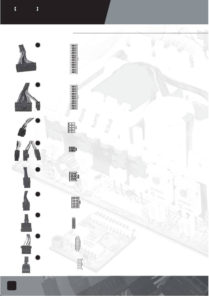
Power supply connectors
5.1
ORANGE
+3.3V
ORANGE
+3.3V
ORANGE
+3.3V
BLUE
-12V
BLACK
GND
BLACK
GND
RED
+5V
GREEN
PS-ON
EPS 24-pin motherboard power connector
BLACK
GND
BLACK
GND
RED
+5V
BLACK
GND
Support the latest ATX/BTX PC motherboard
BLACK
GND
BLACK
GND
GREY
PS-ON
N/C
Support EEB/CEB server/workstation motherboard
PURPLE
+5Vsb
RED
+5V
YELLOW
+12V
RED
+5V
YELLOW
+12V
RED
+5V
ORANGE
+3.3V
BLACK
GND
5.2
ORANGE
+3.3V
ORANGE
+3.3V
ORANGE
+3.3V
BLUE
-12V
BLACK
GND
BLACK
GND
RED
+5V
GREEN
PS-ON
ATX 20-pin motherboard power connector
BLACK
GND
BLACK
GND
RED
+5V
BLACK
GND
BLACK
GND
Support ATX PC motherboard
GND
BLACK
GREY
PS-ON
N/C
PURPLE
+5Vsb
RED
+5V
YELLOW
+12V
RED
+5V
5.3
BLACK
EPS 8-pin CPU +12V power connector
GND
YELLOW
+12V
BLACK
GND
YELLOW
+12V
BLACK
Support Dual CPU server/ workstation
GND
YELLOW
+12V
BLACK
GND
YELLOW
+12V
Support latest single CPU system
5.4
ATX 4-pin CPU +12V power connector
BLACK
GND
YELLOW
+12V
BLACK
GND
YELLOW
+12V
Support latest single CPU system.
PCI-E 6-pin power connector
5.5
YELLOW
Support high-end PCI-Express video card,
+12V
BLACK
GND
YELLOW
+12V
BLACK
SENSE
YELLOW
+12V
GND
some high-end video cards may require two
BLACK
PCI-E 6 pin connectors.
PCI-E 8 pin power connector
5.6
Support high-end PCI-Express video card,
YELLOW
+12V
BLACK
GND
YELLOW
+12V
BLACK
SENSE
some high-end video cards may require
YELLOW
+12V
BLACK
GND
BLACK
SENSE
BLACK
GND
another PCI-E 6-pin connector in addition to
PCI-E 8pin connector.
5.7
YELLOW
+12V
BLACK
GND
SATA hard disk power connector
RED
+5V
BLACK
GND
Support latest SATA hard drives and devices
ORANGE
+3.3V
5.8
YELLOW +12V
Standard 4-pin peripheral power connector
BLACK
GND
Support IDE/SCSI hard drives, optical drives,
BLACK
GND
RED
+5V
fans, etc...
5.9
YELLOW +12V
Small 4-pin floppy power connector
BLACK
GND
Support standard floppy drives or compatible
BLACK
GND
RED
+5V
devices
5
ENGLISH
PSU product manual
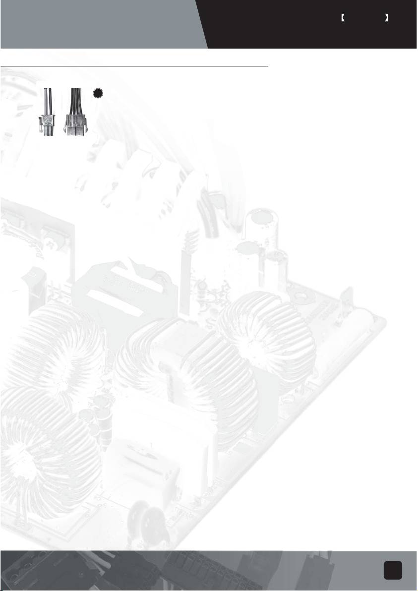
Power supply connectors
5.10
Converting wire
EPS 8-pin connector to convert into ATX 4-pin connector
Caution:
1. Please turn off your system and switch to "O" mode on the power supply before attaching or
detaching power connectors.
2. All power connectors are keyed to prevent incorrect connections. If you cannot connect them
easily, please double check to ensure the connector's direction and type before attempting to
connect again. Do not attach the connector by force; incorrect connection will damage power
supply or devices in your system.
3. The converting wire (picture 5.10) can only be attached with EPS 8-pin connector to convert
into ATX 4-pin connecter. Incorrect connection will damage power supply or devices in your
system.
The connectors shown above may differ depending on the model of your
power supply.
Warranty
Product component defects or damages resulted in defective production is covered under
warranty. Damages resulted with the following conditions will be fixed or replaced under
SilverStone's jurisdiction.
1. Usage in accordance with instructions provided in this manual, with no misuse, overuse,
or other inappropriate actions.
2. Damage not caused by natural disaster (thunder, fire, earthquake, flood, salt, wind,
insects, animals etc...)
3. Product is not disassembled, modified, or fixed. Components not disassembled or replaced.
4. Warranty mark/stickers is not removed or broken.
Loss or damages resulted from conditions other than ones listed above
are not covered under warranty.
6
Table of contents
- PSU product manual
- PSU Bedienungsanleitung
- Manuel de produit PSU
- Manuale PSU su prodotti
- Manual de Productos PSU
- Руководство продукции PSU
- Руководство продукции PSU
- PSU ᮟٴߡ⦝⤵ᮢ༆ҩ
- PSU ᮟٴߡ⦝⤵ᮢ༆ҩ
- PSU ᮟٴߡ⦝⤵ᮢ༆ҩ
- PSU ᮟٴߡ⦝⤵ᮢ༆ҩ
- PSU ᮟٴߡ⦝⤵ᮢ༆ҩ
- PSU ᮟٴߡ⦝⤵ᮢ༆ҩ
- PSUᮟٴߡ⦝⤵ᮢ༆ҩ
- PSUᮟٴߡ⦝⤵ᮢ༆ҩ
- PSUᮟٴߡ⦝⤵ᮢ༆ҩ
- PSUᮟٴߡ⦝⤵ᮢ༆ҩ
- PSUᮟٴߡ⦝⤵ᮢ༆ҩ
- PSUᮟٴߡ⦝⤵ᮢ༆ҩ
