Partner P350S 2014: instruction
Class: Country house and garden equipment
Type: Petrol tool/petrol trimmer
Manual for Partner P350S 2014

P350S
INSTRUCTION MANUAL
IMPORTANT INFORMATION
: Please read these instructions carefully and make
GB
sure you understand them before using this unit. Retain these instructions for future
reference.
ИНСТРУКЦИЯ ПО ЭКСПЛУАТАЦИИ
ВАЖНАЯ ИНФОРМАЦИЯ:
Пожалуйста, внимательно прочтите данную
RU
инструкцию перед тем, как приступить к зксппуатации триммера, и убедитесь что
она вам понятна. Сохраните инструкцию для дальнейшего обращения к ней.
ANVÄNDARHANDBOK
VIKTIG INFORMATION
: Läs dessa anvisningar noggrant och se till att du förstår
SE
dem innan du använder trimmeren och spara dem för framtida behov.
BRUKERHÅNDBOK
VIKTIG INFORMASJON:
Vennligst les disse instruksjonene nøye og pass på at De
NO
forstår dem før De bruker trimmeren og oppbevar den for senere bruk.
BRUGERHÅNDBOG
VIGTIGE OPLYSNINGER:
Læs venligst disse instruktioner omhyggeligt og vær
DK
sikker på, at De forstår dem, før De anvender græstrimmeren og gemme til senere
henvisning.
KÄYTTÖOHJEKIRJA
TÄRKEÄÄ:
Lue tämä ohjekirja huolellisesti läpi ennen kuin alat käyttää laitetta.
FI
Säilytä ohjekirja myöhempää käyttöä varten.
INSTRUKCJA OBSŁUGI
WAZNE INFORMACJE:
Przed rozpoczęciem użytkowania urządzenia, należy
PL
uważnie przeczytać i zrozumieć ninijszą instrukcją. Instrukcje należy przechowywać
do późniejszego z niej korzystania.
NÁVOD K POUŽĺVÁNĺ
DŮLEŽITÁ INFORMACE:
Prosíme, než začnete zařízení používat, přečtěte si
CS
pečlivě tyto pokyny a ujistěte se, že jim plně rozumíte.
9096-312006 Rev. 5 12/11/13

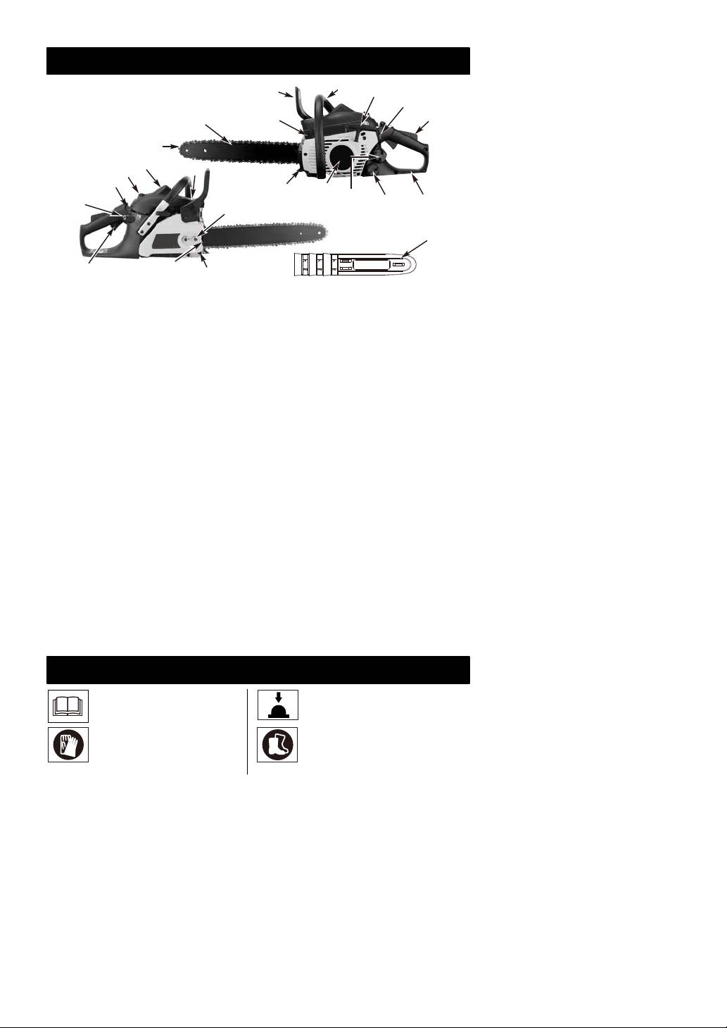
IDENTIFICATION (WHAT IS WHAT?)
5
4
6
7
3
8
2
1
16
17
15
18
13
12
11
19
10
9
14
23
20
21
22
1. Saw chain
9. Rear Handle / Boot Loop
18. Choke Lever for Auto
2. Guide Bar
10. Oil Tank cap
Choke
3. Spark Arrester Screen
11. Fuel Tank Cap
19. Primer Bulb
4. Chain Brake Lever / Hand
12. Starter Cover
20. Throttle trigger
Guard
13. Spiked Bumper
21. Saw Chain Adjustment
5. Front Handle
14. Bar Retaining Nuts
Screw
6. Starter Handle
15. Muffler Shield
22. Chain Catcher
7. ON/OFF Switch
16. Spark Plug
23. Guide-bar Cover
8. Throttle trigger lockout
17. Air Cleaner Cover
SAFETY FEATURES
Numbers preceding the descriptions correspond with the numbers above to help you locate
the safety feature.
1 LOW KICKBACK SAW CHAIN helps
4 CHAIN BRAKE is a safety feature
significantly reduce kickback, or the
designed to reduce the possibility of
intensity of kickback, due to specially
injury due to kickback by stopping a
designed depth gauges and guard
moving saw chain in milliseconds. It is
links.
activated by the CHAIN BRAKE lever.
3 SPARK ARRESTER SCREEN retains
7 STOP SWITCH immediately stops
carbon and other flammable
the engine when tripped. Stop switch
particles over 0.023 inches (0.6mm)
must be pushed to ON position to start
in size from engine exhaust flow.
or restart engine.
Compliance with local, state and
8 THROTTLE TRIGGER LOCKOUT
federal laws and/or regulations
prevents accidental acceleration of the
governing the use of a spark arrester
engine. Throttle trigger (20) cannot be
screen is the user’s responsi-
squeezed unless the safety latch is
bility. See Safety Precautions for
depressed.
additional
information.
22 CHAIN CATCHER reduces the danger
4 CHAIN BRAKE LEVER / HAND
of injury in the event saw chain breaks
GUARD protects the operator’s left
or derails during operation. The chain
hand in the event it slips off the front
catcher is designed to intercept a
handle while saw is running.
whipping chain.
IDENTIFICATION OF SYMBOLS
Read and understand the Instr-
uction Manual and all warning
Primer Bulb
labels before using the machine.
Wear gloves to protect
Wear safety boots to protect
your hands
your feet
-- 2 --

Whenever the machine is in use,
Guaranteed sound power level
safety glasses must be worn to
LWA accordance with directive
safeguard against flying objects.
2000/14/EC + 2005/88/EC
Ear protection must also be used
in order to protect to operators
hearing. If the operator is
working in an area where there is
Sound pressure level at 7,5
a risk of falling objects a safety
meters
helmet must also be worn.
WARNING:
Always use two hands when
Danger
operating the chain saw.
Make Sure the Chain Brake is
disengaged! Pull Hand Guard/
Chain Brake back to run.
This product is in accordance
with applicable EC directives.
SAFETY RULES
• DO NOT allow other persons to be near
WARNING: This tool is designed
when starting or cutting with the chain
only for use by one operator and intended
saw. Keep bystanders and animals out of
for forest work. This tool is designed only to
the work area.
be operated with the right hand on the rear
• DO NOT start cutting until you have a
handle and the left hand on the front handle.
clear work area, secure footing, and a
The operator must read and understood the
planned retreat path from the falling tree.
safety requirements in the instruction
• Keep all parts of your body away from the
handbook and using the appropriate
saw chain when the engine is running.
personal protective equipment (PPE) before
• Before you start the engine, make sure
operating this tool. This tool is not designed
that the saw chain is not contacting
for cutting unintended material, such as
anything.
rubber, stone, metals or wood products not
• Carry the chain saw with the engine
clear of foreign objects.
stopped, the guide bar and saw chain to
the rear, and the muffler away from your
WARNING: When using gas tools,
body.
basic safety precautions, including the
• DO NOT operate a chain saw that is
following, should always be followed to
damaged, improperly adjusted, or not
reduce the risk of serious personal injury
completely and securely assembled. Be
and/or damage to the unit. Read all these
sure that the saw chain stops moving
instructions before operating this product
when the throttle control trigger is
and save these instructions.
released.
WARNING: This machine produces
• Shut off the engine before setting the
an electromagnetic field during operation.
chain saw down.
This field may under some circumstances
• Use extreme caution when cutting small
interfere with active or passive medical
size brush and saplings because slender
implants. To reduce the risk of serious or
material may catch the saw chain and be
fatal injury, we recommend persons with
whipped toward you or pull you off
medical implants to consult their physician
balance.
and the medical implant manufacturer
• When cutting a limb that is under tension,
before operating this machine.
be alert for springback so that you will
not be struck when the tension in the
• DO NOT operate a chain saw with one
wood fibers is released.
hand! Serious injury to the operator,
• Keep the handles dry, clean, and free of
helpers, bystanders, or any combination
oil or fuel mixture.
of these persons may result from one-
• Operate the chain saw only in
handed operation. A chain saw is
well-ventilated areas.
intended for two-handed use.
• DO NOT operate a chain saw in a tree
• DO NOT operate a chain saw when you
unless you have been specifically trained
are fatigued, under the influence of drugs,
to do so.
alcohol or medication.
• All chain saw service, other than the
• Use safety footwear, snug-fitting clothing,
items listed in the user manual safety and
protective gloves, and eye, hearing
maintenance instructions, should be
and head protection devices.
performed by competent chain saw
• Use caution when handling fuel. To
service personnel.
avoide fire, move the chain saw at least
• When transporting your chain saw, use
10 feet (3m) from the fueling point before
the appropriate guide bar scabbard.
starting the engine.
-- 3 --
108
WARNING! Contacting the
guide bar tip with any object
should be avoided; tip contace
may cause the guide bar to
move suddenly upward and
backward. which may cause
serious injury.

• Tighten the cap of oil and fuel tank to
• Wear gloves and keep your hand warm.
prevent the loss of oil and fuel during
Prolonged use of chainsaws exposing the
transport.
operator to vibrations may produce
• DO NOT operate your chain saw near or
whitefinger disease.In order to reduce the
around flammable liquids or gases
risk of whitefinger disease, please wear
whether in or out of doors. An explosion
gloves and keep your hand warm.If any of
and/or fire may result.
the whitefinger symptoms appear, seek
• Do not fill fuel tank, oil tank or lubricate
medical advice immediately.
when the engine is running.
• When transporting or storing the chain
• USE THE RIGHT TOOL: Cut wood
saw always fit the guide bar cover.
only. Do not use the chain saw for
• Drive in the spiked bumper of the chain
purposes for which it was not
saw directly behind the intended hinge
intended. For example, do not use the
and pivot the saw around this point. The
chain saw for cutting plastic, masonry, or
spiked bumper rolls against the trunk.
nonbuilding materials.
• There are 3 parts only, chain, bar and
• The first time user should have practical
spark plug, can be replaced by the user
instruction in manual page 10 (barking
themselves and please use the same type
Saw horse) in the use of chain saw and
as showed on the specifications in the
the protective equipment form an
user's manual.
experienced operator.
(Type for the plug is NGK CMR7H).
• Do not attempt to hold the saw with one
If the other components beyond the prior
hand only. You cannot control reactive
parts are defective, then please take your
forces and you may lose control of the
tools to the nearest Authorized Service
saw, which can result in the skating or
Center for service.
bouncing of the bar and chain along the
NOTE: This appendix is intended primarily
limb or log.
for the consumer or occasional user. These
• Never run the chainsaw indoors.
models are intended for infrequent use by
Your chainsaw produces poisonous
homeowners, cottagers, and campers, and
exhaust as soon as the combustible
for such general applications as clearing,
engine is started, which may be colorless
pruning, cutting firewood, etc. They are not
and odorless. To
use this product can
intended for prolonged use. If the intended
generate dust, mists and fumes
use involves prolonged periods of opera-
containing chemicals known to cause
tion, this may cause circulatory problems in
reproductive harm. Be aware of harmful
the user’s hands due to vibration.
dust, mist (such as saw dust or oil mist
from chain lubrication) and protect your
self properly.
KICKBACK SAFETY PRECAUTIONS
KICKBACK may occur when the NOSE or
handle, when the engine is running. Use
TIP of the guide bar touches an object, or
a firm grip with thumbs and fingers
when wood closes in and pinches the saw
encircling the chain saw handles. A firm
chain in the cut.
grip will help you reduce kickback and
Tip contact in some cases may cause a
maintain control of the saw. Don’t let go.
lightning-fast reverse reaction, kicking the
3. Make sure that the area in which you are
guide bar up and back toward the operator.
cutting is free from obstructions. Do not
PINCHING the saw chain along the
let the nose of the guide bar contact a
BOTTOM of the guide bar may PULL the
log, branch, or any other obstruction
saw forward away from the operator.
which could be hit while you are
PINCHING the saw chain along the TOP of
operating the saw.
the guide bar may PUSH the guide bar
4. Cut at high engine speeds.
rapidly back toward the operator.
5. Do not overreach or cut above shoulder
Any of these reactions may cause you to
height.
lose control of the saw, which could result in
6. Follow manufacturer’s sharpening and
serious personal injury.
maintenance instructions for the saw
chain.
1. With a basic understanding of kickback,
7. Only use replacement bars and chains
you can reduce or eliminate the element
specified by the manufacturer or the
of surprise. Sudden surprise contributes
equivalent.
to accidents.
2. Keep a good firm grip on the saw with
NOTE: Low-kickback saw chain is chain
both hands, the right hand on the rear
that has met the kickback performance.
handle, and the left hand on the front
-- 4 --

IMPORTANT SAFETY
Your Chain Saw is provided with a safety
DANGER! BEWARE OF KICKBACK!
label located on the chain brake lever/hand
guard. This label, along with the safety
WARNING:
Kickback can lead to
instructions on these pages, should be
dangerous loss of control of the chain saw
carefully read before attempting to operate
and result in serious or fatal injury to the
this unit.
saw operator or to anyone standing close
HOW TO READ SYMBOLS AND
by. Always be alert. Rotational kickback
and pinch-kickback are major chain saw
COLORS (FIG.1)
operational dangers and the leading cause
of most accidents.
WARNING: RED Used to warn that
an unsafe procedure should not be
performed.
A
RECOMMENDED
A
B
Recommended cutting procedure.
B
1
3
Fig. 1
C
Fig. 2A Fig. 2B
2
4
BEWARE OF:
ROTATIONAL
THE PUSH (PINCH
WARNING
KICKBACK
KICKBACK) AND
1. Beware of kickback.
(Fig. 2A)
PULL REACTIONS
2. Do not attempt to hold saw with one
(Fig. 2B)
A = Kickback path
hand.
B = Kickback
A = Pull
3. Avoid bar nose contact.
reaction zone
B = Solid objects
RECOMMENDED
C = Push
4. Hold saw properly with both hands.
ASSEMBLY INSTRUCTIONS
TOOLS FOR ASSEMBLY
GUIDE BAR / SAW CHAIN / CLUTCH
You will need these tools to assemble your
COVER INSTALLATION
chain saw:
WARNING: Always wear protective
1. Combination wrench-screwdriver (cont-
gloves when handling chain.
ained in your user’s kit).
2. Heavy duty work gloves (user supplied).
TO INSTALL GUIDE BAR:
To ensure the bar and chain receive oil,
ASSEMBLY REQUIREMENTS
ONLY USE THE ORIGINAL STYLE BAR
with the oil passage hole (A) as illustrated
WARNING: DO NOT start saw
above. (Fig.3A)
engine until unit is properly prepared.
1. Make sure the CHAIN BRAKE lever is
Your new chain saw will require adjustment
pulled back into the DISENGAGED
of chain, filling the fuel tank with correct fuel
position (Fig. 3B)
mixture and filling the oil tank with
2. Remove the bar retaining nut
lubricating oil before the unit is ready for
(B). Remove the CHAIN BRAKE cover
operation.
(C) by pulling straight out, some force
Read the entire user manual before
may be required. (Fig.3C).
attempting to operate your unit. Pay
Note: Discard the two plastic washers.They
particular attention to all safety precautions.
are only used for shipping the chain saw.
Your user manual is both a reference guide
3. Using a screwdriver, turn the adjustm-
and handbook provided to furnish you with
ent screw (D) COUNTERCLOCKWISE
general information to assemble, operate
until the TANG (E) (projecting prong) is to
and maintain your saw.
the end of its travel (Fig. 3D).
4. Place the slotted end of the guide bar
over the bar bolt (F). Slide guide bar
behind clutch drum
(G) until the guide
bar stops (Fig.3E).
-- 5 --

A
Taking the time to make needed
adjustments to the saw chain will result in
improved cutting performance and
prolonged chain life.
WARNING: Always wear heavy duty
Fig. 3A
Fig. 3B
gloves when handling saw chain or making
saw chain adjustments.
D
C
TO ADJUST SAW CHAIN:
E
1. Hold nose of guide bar up and turn
B
adjustment screw (A) CLOCKWISE to
increase chain tension. Turning screw
Fig. 3C
Fig. 3D
COUNTERCLOCKWISE will decrease
amount of tension on chain. Ensure the
chain fits snugly all the way around the
F
guide bar (Fig. 5).
2. After making adjustment, and while still
holding nose of bar in the uppermost
position, tighten the bar retaining nuts
G
securely. Chain has proper tension
Fig. 3E
when it has a snug fit all around and
can be pulled around by gloved hand.
TO INSTALL SAW CHAIN:
NOTE: If chain is difficult to rotate on
Always wear heavy duty gloves when
guide bar or if it binds, too much tension
handling saw chain or making saw chain
has been applied. This requires minor
adjustments.
adjustment as follows:
1. Spread chain out in a loop with cutting
A. Loosen the bar retaining nuts so they
edges (A) pointing CLOCKWISE around
are finger tight. Decrease tension by
loop (Fig. 4A).
turning the bar adjustment screw
2. Slip the chain around the sprocket (B)
COUNTERCLOCKWISE slowly. Move
behind the clutch (C). Make sure the
chain back and forth on bar. Continue to
links fit between the sprocket teeth
adjust until chain rotates freely, but fits
(Fig. 4B).
snugly. Increase tension by turning bar
3. Guide the drive links into the groove (D)
adjustment screw CLOCKWISE.
and around the end of the bar (Fig. 4B).
B. When saw chain has proper tension,
NOTE: The saw chain may droop slightly on
hold nose of bar in the uppermost
the lower part of bar. This is normal.
position and tighten the 2 bar
retaining
nuts securely.
4. Pull guide bar forward until chain is
snug. Ensure all drive links are in the bar
CAUTION: A new saw chain
groove.
stretches, requiring adjustment after as
5. Install the clutch cover making sure the
few as 5 cuts. This is normal with a new
tang is positioned in the lower hole in the
chain, and the interval between future
guide bar. Make sure the chain does not
adjustments will lengthen quickly.
slip off of the bar. Install the bar retaining
nut hand tight and follow tension
adjustment instructions in Section
A
SAW CHAIN TENSION
ADJUSTMENT.
NOTE: The guide bar retaining nuts are
installed only hand tight at this point
Fig. 5
because saw chain
adjustment is
required. Follow instructions in Section
CAUTION: If saw chain is TOO
SAW CHAIN TENSION ADJUSTMENT.
LOOSE or TOO TIGHT, the sprocket, bar,
A
B
D
chain, and crankshaft bearings will wear
more rapidly. Study Fig. 6 for information
concerning correct cold tension (A),
correct warm tension (B), and as a guide for
when saw chain needs adjustment (C).
C
Fig. 4A
Fig. 4B
SAW CHAIN TENSION ADJUSTMENT
Proper tension of saw chain is extremely
important and must be checked before
A
C
B
starting, as well as during any cutting
operation.
Fig. 6
-- 6 --

CHAIN BRAKE MECHANICAL TEST
2. The CHAIN BRAKE is ENGAGED (chain
Your chain saw is equipped with a Chain
is stopped) when brake lever is in forward
brake that reduces possibility of injury due to
position and the chain brake latch is in
kickback. The brake is activated if pressure
the ON position. You should not be able
is applied against brake lever when, as in
to move chain. (Fig. 7B)
the event of kickback, operator’s hand
NOTE:The brake lever should snap into both
strikes the lever. When the brake is actuated,
positions. If strong resistance is felt, or lever
chain movement stops abruptly.
does not move into either position, do not use
your saw. Take it immediately to a
WARNING: The purpose of the
professional Service Center for repair.
chain brake is to reduce the possibility of
injury due to kickback; however, it cannot
OFF
ON
provide the intended measure of protection
if the saw is operated carelessly. Always
test the chain brake before using your saw
and periodically while on the job.
TO TEST CHAIN BRAKE:
Fig. 7A Fig. 7B
1. The CHAIN BRAKE is DISENGAGED
(chain can move) when BRAKE LEVER
IS PULLED BACK AND LOCKED. Be
sure the chain brake latch is in the OFF
position. (Fig. 7A)
FUEL AND LUBRICATION
FUEL
FUEL MIXING TABLE
Use regular grade unleaded gasoline
GASOLINE 40:1 Ratio
mixed with 40:1 custom 2-cycle engine oil
Custom Lubricant
for best results. Use mixing ratios in Section
1 U.S. Gal. 3.2 oz. 95ml (cc)
FUEL MIXINGTABLE.
5 Liters 4.3 oz. 125ml (cc)
WARNING: Never use straight
1 lmp. Gal.
4.3 oz. 125ml (cc)
gasoline in your unit. This will cause
Mixing 40 Parts Gasoline
permanent engine damage and void the
Procedure to 1 part Lubricant
manufacturer’s warranty for that product.
Never use a fuel mixture that has been
1ml = 1cc
stored for over 90 days.
RECOMMENDED FUELS
WARNING: Lubricant must be a
Some conventional petrols are being
premium grade oil for 2-stroke air cooled
blended with oxygenates such as alcohol or
engines mixed at a 40:1 ratio. Do not use any
an ether compound to meet clean air
2-cycle oil product with a recommended
standards.Your engine is designed to operate
mixing ratio of 100:1. If insufficient lubrication
satisfactorily on any gasoline intended for
is the cause of engine damage, it voids the
automotive use including oxygenated
manufacturer’s engine warranty for that
petrols.
occurrence.
CHAIN AND BAR LUBRICATION
MIXING FUEL
Always refill the chain oil tank each time the
Mix fuel with 2 cycle oil in an approved
fuel tank is refilled. We recommend using
container. Use mixing table for correct
Partner Chain, Bar and Sprocket Oil, which
ratio of fuel to oil. Shake container to
contains additives to reduce friction and
ensure thorough mix.
wear and to assist in the prevention of pitch
formation on the bar and chain.
WARNING: Lack of lubrication voids
engine warranty.
FUEL AND LUBRICATION
Gasoline and Oil
Oil Only
Mix 40:1
-- 7 --

OPERATION
ENGINE PRE-START CHECKS
C
WARNING: Never start or operate
the saw unless the bar and chain are
properlyinstalled.
D
1. Fill the fuel tank (A) with correct fuel
mixture. (Fig. 8).
Fig. 9E Fig. 9F
2. Fill the oil tank (B) with correct chain and
RE-STARTING A WARM ENGINE
bar oil (Fig. 8).
3. Be certain the chain brake is disengaged
1. Make sure the on/off switch is in the “I”
(C) before starting unit (Fig. 8).
position.
2. Depress the primer bulb 10 times.
C
3. Pull the starter rope rapidly 4
A
times. The engine should start.
4. If the engine still can not start, follow the
step as “To start engine” in this user
manual.
B
TO STOP ENGINE
Fig. 8
1. Release trigger
and allow engine
TO START ENGINE
to return to idle
1. Move ON/OFF switch to ON “I”
speed.
position. (Fig. 9A)
2. Press STOP switch
2. Pull choke lever/throttle (A) advance. This
down to stop
sets choke and advances throttle for
engine Figure 9G.
easier starting. (Fig. 9B)
Fig. 9G
NOTE: For emerge-
3. Press primer bulb (B) 10 times. (Fig. 9C)
ncy stopping, simply
4. With saw on ground, grip front handle
activate CHAIN BRAKE and move
firmly with left hand and place right foot
STOP switch down.
inside rear handle. Pull starter rope 4
times with right hand. (Fig. 9D)
CHAIN BRAKE OPERATIONAL TEST
NOTE: Easy Start significant reduce the
Test the CHAIN BRAKE periodically to
effort required to start the engine. You must
ensure proper function.
pull the starter rope out far enough to hear
Perform a CHAIN BRAKE test prior to initial
the engine attempt to start. There is no need
cutting, following extensive cutting, and
to pull the rope briskly-- there is no harsh
definitely following any CHAIN BRAKE
resistance when pulling. Be aware that this
service.
starting method is vastly different from (and
TEST CHAIN BRAKE AS FOLLOWS:
much easier than) what you may be used to.
5. Push choke lever (C) in
1. Place saw on a clear, firm, flat surface.
completely. (Fig. 9E)
2. Start engine.
6. Pull starter rope quickly until engine
3. Grasp the rear handle (A) with your right
starts.
hand (Fig. 10).
7. Allow the engine to run for about 10
4. With your left hand, hold the front
seconds. Squeeze and release throttle
handle (B) [not CHAIN BRAKElever (C)]
trigger (D) to idle engine. (Fig. 9F)
firmly (Fig. 10).
8. If the eingine does not start up, repeat
5. Squeeze the throttle trigger to 1/3 throttle,
the above steps.
then immediately activate
the CHAIN
BRAKElever (C) (Fig. 10).
6. Chain should stop abruptly. When it does,
A
immediately release the throttle trigger.
WARNING: Activate the chain brake
slowly and deliberately. Keep the chain
from touching anything; don t let the saw tip
Fig. 9A Fig. 9B
forward.
7. If chain brake functions properly, turn the
B
engine off and return the chain brake to
the DISENGAGED position.
WARNING: If chain does not
stop, turn engine off and take your unit to
Fig. 9C Fig. 9D
the nearest Authorized Service Center for
service.
-- 8 --

B
occasionally be necessary to adjust and
A
C
tighten it. New chain will require adjustment
after about 5 minutes of operation.
AUTOMATIC OILER
Fig. 10
Your chain saw is equipped with an
automatic clutch driven oiler system. The
SAW CHAIN / BAR LUBRICATION
oiler automatically delivers the proper
Adequate lubrication of the saw chain is
amount of oil to the bar and chain. As the
essential at all times to minimize friction with
engine speed increases, so does the oil flow
the guide bar.
to the bar pad. There is no flow adjustment.
Never starve the bar and chain of oil.
The oil reservoir will run out at approximately
Running the saw with too little oil will
the same time as the fuel supply runs out.
decrease cutting efficiency, shorten saw
WARNING: Don't put pressure on
chain life, cause rapid dulling of chain, and
the saw when reaching the end of the cut.
cause excessive wear of bar from
The pressure may cause the bar and chain
overheating. Too little oil is evidenced by
to rotate. If the rotating chain strikes some
smoke, bar discoloration or pitch build-up.
other object, a reactive force may cause
NOTE: Saw chain stretches during use,
moving chain to strike the operator.
particularly when it is new, and it will
GENERAL CUTTING INSTRUCTIONS
FELLING
GENERAL GUIDELINES FOR FELLING
Felling is the term for cutting down a tree.
TREES:
Small trees up to 6-7 inches (15-18cm) in
Normally felling consists of 2 main cutting
diameter are usually cut in a single cut.
operations, notching (C) and making the
Larger trees require notch cuts. Notch cuts
felling cut (D).
determine the direction the tree will fall.
Start making the upper notch cut (C) on the
side of the tree facing the felling direction
FELLING A TREE:
(E). Be sure you don t make the lower cut
too deep into the trunk.
WARNING: A retreat path (A) should
be planned and cleared as necessary before
The notch (C) should be deep enough to
cuts are started. The retreat path should
create a hinge (F) of sufficient width and
extend back and diagonally to the rear of the
strength. The notch should be wide enough
expected line of fall, as illustrated in
to direct the fall of the tree for as long as
Fig.11A.
possible.
CAUTION: If felling a tree on sloping
WARNING: Never walk in front of a
ground, the chain saw operator should keep
tree that has been notched.
on the uphill side of the terrain, as the tree is
Make the felling cut (D) from the other side of
likely to roll or slide downhill after it is felled.
the tree and 1.5 - 2.0 inches (3-5 cm) above
the edge of the notch (C) (Fig.11B)
NOTE:Direction of fall (B) is controlled by the
notching cut. Before any cuts are made,
consider the location of larger branches and
natural lean of the tree to determine the way
the tree will fall.
B
Fig. 11B
A
Never saw completely through the trunk.
Always leave a hinge. The hinge guides the
tree. If the trunk is completely cut through,
control over the felling direction is lost.
Fig. 11A
Insert a wedge or felling lever in the cut well
before the tree becomes unstable and starts
WARNING: Do not cut down a tree
to move. This will prevent the guidebar from
during high or changing winds or if there is a
binding in the felling cut if you have
danger to property. Consult a tree
misjudged the falling direction. Make sure no
professional. Do not cut down a tree if there
bystanders have entered the range of the
is a danger of striking utility wires; notify the
falling tree before you push it over.
utility company before making any cuts.
-- 9 --

BUCKING
WARNING: Before making the final
Bucking is cutting a fallen log into lengths.
cut, always recheck the area for bystanders,
Make sure you have a good footing and
animals or obstacles.
stand uphill of the log when cutting on
FELLING CUT:
sloping ground. If possible, the log should
be supported so that the end to be cut off is
1. Use wooden or plastic wedges (A) to
not resting on the ground. If the log is
prevent binding the bar or chain (B) in the
supported at both ends and you must cut in
cut. Wedges also control felling
the middle, make a downward cut halfway
(Fig.11C).
through the log and then make the
2. When diameter of wood being cut is
undercut. This will prevent the log from
greater than the bar length, make 2 cuts
pinching the bar and chain. Be careful that
as shown (Fig.11D).
the chain does not cut into the ground when
bucking as this causes rapid dulling of the
A
B
chain.
When bucking on a slope, always stand on
the uphill side.
1. Log supported along entire length: Cut
from top (overbuck), being careful to
avoid cutting into the ground (Fig. 13A).
Fig. 11DFig. 11C
2. Log supported on 1 end: First, cut from
bottom (underbuck) 1/3 diameter of log to
WARNING: As the felling cut gets
avoid splintering. Second, cut from above
close to the hinge, the tree should begin to
(overbuck) to meet first cut and avoid
fall. When tree begins to fall, remove saw
pinching (Fig. 13B).
from cut, stop engine, put chain saw down,
3. Log supported on both ends: First,
and leave area along retreat path (Fig.11A).
overbuck 1/3 diameter of log to avoid
LIMBING
splintering. Second, underbuck to meet
first cut and avoid pinching (Fig. 13C).
Limbing a tree is the process of removing
the branches from a fallen tree. Do not
NOTE: The best way to hold a log while
remove supporting limbs (A) until after the
bucking is to use a sawhorse. When this is
log is bucked (cut) into lengths (Fig.12).
not possible, the log should be raised and
Branches under tension should be cut from
supported by the limb stumps or by using
the bottom up to avoid binding the chain
supporting logs. Be sure the log being cut is
saw.
securely supported.
BUCKING USING A SAWHORSE
WARNING: Never cut tree limbs
while standing on tree trunk.
For personal safety and ease of cutting, the
correct position for vertical bucking is
essential (Fig.14).
VERTICAL CUTTING:
A. Hold the saw firmly with both hands and
A
keep the saw to the right of your body
while cutting.
Fig. 12
Fig. 13A
B. Keep the left arm as straight as possible.
C. Keep weight on both feet.
CAUTION: While the saw is cutting,
be sure the chain and bar are being properly
lubricated.
Fig. 13B
Fig. 13C
B
A
C
600mm
Fig. 14
-- 10 --

MAINTENANCE INSTRUCTIONS
All chain saw service, other than items listed
C
here in your user manual maintenance
instructions, should be performed by a
professional.
B
PREVENTIVE MAINTENANCE
D
A
A good preventive maintenance program of
regular inspection and care will increase life
Fig. 15A
Fig. 15B
and improve performance of your chain saw.
This maintenance checklist is a guide for
B
F
such a program.
F
Cleaning, adjustment, and parts replacement
E
may be required, under certain conditions, at
more frequent intervals than those indicated.
MAINTENANCE
HOURS OF
CHECKLIST
EACH
OPERATION
Fig. 15C
Fig. 15D
USE
ITEM ACTION
10 20
FUEL FILTER
Screws/Nuts/Bolts Inspect/Tighten
WARNING: Never operate your saw
Air Filter Clean or Replace
without a fuel filter. The fuel filter should be
Fuel Filter/Oil Filter Replace
replaced after each 20 hours of use. Drain
Spark Plug Clean/Adjust/Replace
fuel tank completely before changing filter.
Spark Arrester Screen Inspect
1. Remove the fuel tank cap.
Replace as Required
2. Bend a piece of soft wire to from a hook at
the end.
Fuel Hoses Inspect
3. Reach into fuel tank opening and hook fuel
Replace as Required
line. Carefully pull the fuel line toward the
Chain brake Inspect
opening until you can reach it with your
components
Replace as Required
fingers.
NOTE: Do not pull hose completely out of
AIR FILTER
tank.
4. Lift filter (A) out of tank (Fig.16).
CAUTION: Never operate saw
5. Pull filter off with a twisting motion. Discard
without the air filter. Dust and dirt will be
filter.
drawn into engine and damage it. Keep the
6. Install new filter. Insert end of filter into
air filter clean!
tank opening. Make sure filter sits in
TO CLEAN AIR FILTER:
bottom corner of tank. Use a long
1. Remove knob (A) holding air filter cover in
screwdriver to aid in filter placement if
place, remove the top cover (B) by
necessary.
loosening the cover retaining screws.
7. Fill tank with fresh fuel / oil mixture. See
Cover will lift off. (Fig.15A)
Section FUEL AND LUBRICATION.
2. Lift the air filter (C) out of air-box (D)
Install fuel cap.
(Fig.15B).
3. Clean air filter. Wash filter in clean, warm,
A
soapy water. Rinse in clear, cool water. Air
dry completely.
NOTE: It is advisable to have a supply of
spare filters.
4. Install air filter. Install engine / air filter
Fig. 16
cover. Make sure latche (E) latch (F) and
cover fit properly. Tighten the cover
SPARK ARRESTER SCREEN
retaining knob securely. (Fig.15C &
NOTE: A clogged spark arrester screen will
Fig.15D)
dramatically reduce engine performance.
1. Remove the 2 bolts (A) and pull muffler
WARNING: Never perform mainten-
out. (Fig. 17A).
ance when the engine is hot, to avoid any
2. Remove the 2 screws that holds the cover
chance of burning hands or fingers.
(C). (Fig.17B)
3. Discard the used spark arrester screen (D)
andreplace it with a new one.
4. Reasemble the muffler components and
install the muffler to the cylinder. Tighten
securely.
-- 11 --

B
C
D
5. Pour 1 teaspoon of clean 2-cycle oil into
A
the combustion chamber. Pull starter rope
slowly several times to coat internal
components. Replace spark plug. (Fig. 19)
NOTE: Store the unit in a dry place and away
B
from possible sources of ignition such as a
B
furnace, gas hot water heater, gas dryer, etc.
Fig. 17A
Fig. 17B
SPARK PLUG
NOTE: For efficient operation of saw engine,
spark plug must be kept clean and properly
gapped.
1. Push STOP switch down.
2. Remove knob (A) holding air filter cover in
place, remove the top cover (B) by
loosening the cover retaining screws.
Fig. 19
Cover will lift off. (Fig.18A)
REMOVING A UNIT FROM STORAGE
3. Disconnect the wire connector (C) from the
1. Remove spark plug.
spark plug (D) by pulling and twisting at the
2. Pull starter rope briskly to clear excess oil
same time (Fig. 18B).
from combustion chamber.
4. Remove spark plug with spark plug socket
3. Clean and gap spark plug or install a new
wrench. DO NOT USE ANY OTHER
spark plug with proper gap.
TOOL.
4. Prepare unit for operation.
5. Check electtrode gaps with wire feeler
5. Fill fuel tank with proper fuel / oil mixture.
gauge and set gaps to .025” (.635mm) if
See FUEL AND LUBRICATION Section.
necessary.
6. Reinstall a new spark plug.
GUIDE BAR MAINTENANCE
NOTE: A resistor spark plug must be used for
Frequent lubrication of the guide bar (railed
replacement.
bar which supports and carries the saw
chain) sprocket tip is required. Proper
NOTE: This spark ignition system meets all
maintenance of the guide bar, as explained in
requirements of the Interference-Causing
this section, is essential to keep your saw in
Equipment Regulations.
good working condition.
SPROCKET TIP LUBRICATION:
C
CAUTION: The sprocket tip on your
B
new saw has been pre-lubricated at the
factory. Failure to lubricate the guide bar
A
D
sprocket tip as explained below will result in
poor performance and seizure, voiding the
Fig. 18A
Fig. 18B
manufacturer’s warranty.
CARBURETOR ADJUSTMENT
Lubrication of the sprocket tip is
The carburetor was preset at the factory for
recommended after 10 hours of use or once
optimum performance. If further adjustments
a week, which ever occurs first. Always
are necessary, please take your unit to the
thoroughly clean guide bar sprocket tip
nearest qualified service technician.
before lubrication.
STORING A CHAIN SAW
TOOLS FOR LUBRICATION:
The Lube Gun (optional) is recommended for
CAUTION: Never store a chain saw
applying grease to the guide bar sprocket tip.
for longer than 30 days without performing
The Lube Gun is equipped with a needle
the following procedures.
nose tip which is necessary for the efficient
Storing a chain saw for longer than 30 days
application of grease to the sprocket tip.
requires storage maintenance. Unless the
storage instructions are followed, fuel
TO LUBRICATE SPROCKET TIP:
remaining in the carburetor will evaporate,
leaving gum-like deposits. This could lead to
WARNING: Wear heavy duty work
difficult starting and result in costly repairs.
gloves when handling the bar and chain.
1. Remove the fuel tank cap slowly to release
1. Press the STOP switch down.
any pressure in tank. Carefully drain the
NOTE: It is not necessary to remove the saw
fuel tank.
chain to lubricate the guide bar sprocket tip.
2. Start the engine and let it run until the unit
Lubrication can be done on the job.
stops to remove fuel from carburetor.
2. Clean the guide bar sprocket tip.
3. Allow the engine to cool (approx. 5
3. Using the Lube Gun (optional), insert
minutes).
needle nose into the lubrication hole and
4. Using a spark plug wrench, remove the
inject grease until it appears at outside
spark plug.
edge of sprocket tip (Fig. 20).
-- 12 --

4. Rotate saw chain by hand. Repeat
WARNING: After 3 to 4 of your
lubrication procedure until the entire
sharpening of the cutting teeth, have the saw
sprocket tip has been greased.
chain sharpened in any authorised service.
They will sharpen the depth limiter as well,
which provides the distance.
CHAIN SHARPENING - The pitch of the
chain (Fig. 21) is 3/8” LoPro x .050”.
Sharpen the chain using protective gloves
and a round file of ø5/32” (4mm).
Fig. 20
Always sharpen the cutters only with outward
strokes (Fig. 22) observing the values given
GUIDE BAR MAINTENANCE:
in Fig. 21.
Most guide bar problems can be
prevented merely by keeping the chain
saw well maintained.
Insufficient guide bar lubrication and
operating the saw with chain that is TOO
TIGHT will contribute to rapid bar wear.
To help minimize bar wear, the following
guide bar maintenance procedures are
Fig. 21
recommended.
WARNING: A sharp chain produces
WARNING: Always wear protective
welldefined chips. When your chain starts to
gloves during maintenance operations. Do
produce sawdust, it is time to sharpen.
not carry out maintenance when the engine is
After sharpening, the cutting links must all
hot.
have the same width and length.
CHAIN SHARPENING:
After every 3-4 times the cutters have been
Chain sharpening requires special tools to
sharpened you need to check the height of
ensure that cutters are sharpened at the
the depth gauges and, if necessary, lower
correct angle and depth. For the
them using the flat file and template supplied
inexperienced chain saw user, we
optional, then round off the front corner.
recommend that the saw chain be
(Fig. 23)
professionally sharpened by the nearest
professional Service Center. If you feel
WARNING: Proper adjustment of the
comfortable sharpening your own saw chain,
depth gauge is as important as proper
special tools are available from the
sharpening of the chain.
professional Service Center. For
non-experienced users of the chain saw, we
recommend to have the chain sharpened by
a specialist in any authorised service.
WARNING: When having wrong
sharpened chain, there may occur a higher
danger of kickback.
Fig. 22 Fig. 23
1. To sharpen the saw chain, use the suitable
GUIDE BAR- The bar should be reversed
sharpen-ing tools:
every 8 working hours to ensure uniform
- Round chain file ø5/32”(4mm).
wear.
- File leading
Keep the bar groove and lubrication hole
- Chain measuring calibre.
clean using a bar groove cleaner (optional).
These tools can be bought in any
(Fig. 24)
specialsed stores.
Check the bar rails frequently for wear and, if
2. To gain well shaped sawdust particles, use
necessary, remove the burs and square-up
sharp chain. If there appears wooden
the rails using a flat file. (Fig.25)
powder, you must sharpen the saw chain.
WARNING: Never mount a new
WARNING: All cutting teeth must be
chain on a worn sprocket or self-aligning ring.
similarly long. Different length of the teeth
can cause rough run of the chain or its
rupture, as well.
3. Minimum length of the teeth must be 4mm.
If they are shorter, remove the saw chain.
4. Angles, which the teeth are under, must be
followed.
5. To sharpen the chain basically, make 2 to
Fig. 24 Fig. 25
3 pulls of the file from the inside out.
-- 13 --

BAR WEAR - Turn guide bar frequently at
BREAKING IN A NEW SAW CHAIN:
regular intervals (for example, after 5
A new chain and bar will need chain
hours of use), to ensure even wear on top
readjustment after as few as 5 cuts. This is
and bottom of bar.
normal during the break-in period, and the
OIL PASSAGES - Oil passages on the bar
interval between future adjustments will
should be cleaned to ensure proper
begin to lengthen quickly.
lubrication of the bar and chain during
operation.
WARNING: Never have more than 3
NOTE: The condition of the oil passages
links removed from a loop of chain. This
can be easily checked. If the passages are
could cause damage to the sprocket.
clear, the chain will automatically give off a
CHAIN LUBRICATION:
spray of oil within seconds of starting the
Always make sure the automatic oiler
saw. Your saw is equipped with an
system is working properly. Keep the oil
automatic oiler system.
tank filled with Chain, Bar and Sprocket Oil.
CHAIN MAINTENANCE
Adequate lubrication of the bar and chain
CHAIN TENSION:
during cutting operations is essential to
Check the chain tension frequently and
minimize friction with the guide bar.
adjust as often as necessary to keep the
Never starve the bar and chain of lubricating
chain snug on the bar, but loose enough to
oil. Running the saw dry or with too little oil
be pulled around by hand.
will decrease cutting efficiency, shorten saw
chain life, cause rapid dulling of chain, and
lead to excessive wear of bar from
overheating. Too little oil is evidenced by
smoke or bar discoloration.
TROUBLESHOOTING TABLE
WARNING:
Always stop unit and disconnect spark plug before performingall of the
recommended remedies below except remedies that require operation of the unit.
PROBLEM
PROBABLE CAUSE
CORRECTIVE ACTION
Unit won’t start or starts
Incorrect starting procedures.
Follow instructions in the User Manual.
but will not run.
Incorrect carburetor mixture
Have carburetor adjusted by an Authorized
adjustment setting.
Service Center.
Fouled spark plug
Clean / gap or replace plug.
Fuel filter plugged.
Replace fuel filter.
Dirty spark arrester screen.
Replace spark arrester screen.
Unit starts, but engine
has low power.
Dirty air filter.
Remove, clean and reinstall filter.
Incorrect carburetor mixture
Have carburetor adjusted by an Authorized
adjustment setting.
Service Center.
Engine hesitates.
Incorrect carburetor mixture
Have carburetor adjusted by an Authorized
No power under load.
adjustment setting.
Service Center.
Runs erratically.
Incorrectly gapped spark plug.
Clean / gap or replace plug.
Smokes excessively.
Incorrect carburetor mixture
Have carburetor adjusted by an Authorized
adjustment setting.
Service Center.
Incorrect fuel mixture.
Use properly mixed fuel (40:1 mixture).
-- 14 --

DECLARATION OF CONFORMITY
Business name of the manufacturer: Husqvarna AB
Full address of the manufacturer: SE-561 82 Huskvarna, Sweden
We declare that the machinery
Product name: Chain saw
Commercial name: Petrol chain saw
Function: Service for tree
Model: P350S
Type: Gasoline powered
Serial number: 11001S100001~21365S999999
Fulfils all the relevant provisions of Directives
2006/42/EC, 2004/108/EC, 2000/14/EC+2005/88/EC,
97/68/EC+2004/26/EC
Based on EC type-examination of
Name, address and identification number of the notified body:
TÜV Reinland LGA Products GmbH
Tillystrasse 2,90431, Nuremberg
Number of the EC type-examination certificate:
BM 50231266
and tested in accordance with below standards
EN ISO 11681-1:2011
EN ISO 14982:2009
The conformity assessment of Directive 2000/14/EC, was done using
Annex V of the Directive. For information regarding noise emissions
and rated net power, see Technical Data Sheet.
Person authorised to compile the technical file and make
this declaration:
Name, surname : Bo R Jonsson
Position/Title : R&D Manager
Address : SE-561 82 Huskvarna, Sweden
Place and date of the declaration: Shanghai, PRC 2013/01/18
-- 15 --

TECHNICAL DATA SHEET
Model No. . . . . . . . . . . . . . . . . . . . . . . . . . . . . . . . . . . . . . . . . . . . . . . . . . . . P350S
Engine Displacement . . . . . . . . . . . . . . . . . . . . . . . . . . . . . . . . . . . . . . . . . . . . . . . . . . . 40 cm
3
(2.4 cu-in)
Rated Net Power . . . . . . . . . . . . . . . . . . . . . . . . . . . . . . . . . . . . . . . . . . . . . . . . . . . . . . 1.52 kW
The Usable Cutting Lengths . . . . . . . . . . . . . . . . . . . . . . . . . . . . . . . . . . . . . . . . . . . . . . 37 cm
Bar Cutting Length . . . . . . . . . . . . . . . . . . . . . . . . . . . . . . . . . . . . . . . . . . . . . . . . . . . . . 40 cm
Chain Pitch . . . . . . . . . . . . . . . . . . . . . . . . . . . . . . . . . . . . . . . . . . . . . . . . . . . . . . . . . . 9,53 mm (3/8”)
Chain Gauge . . . . . . . . . . . . . . . . . . . . . . . . . . . . . . . . . . . . . . . . . . . . . . . . . . . . . . . . . . 1.3 mm (0.05”)
Idle Speed (Max.) . . . . . . . . . . . . . . . . . . . . . . . . . . . . . . . . . . . . . . . . . . . . . . . . . . . . . 3300 min
-1
Recommended maximum speed
with cutting attchment . . . . . . . . . . . . . . . . . . . . . . . . . . . . . . . . . . . . . . . . . . . . . . . . . . 12500 min
-1
Fuel Capacity . . . . . . . . . . . . . . . . . . . . . . . . . . . . . . . . . . . . . . . . . . . . . . . . . . . . . . . . . 250 cm
3
Oil Capacity . . . . . . . . . . . . . . . . . . . . . . . . . . . . . . . . . . . . . . . . . . . . . . . . . . . . . . . . . . 150 cm
3
Anti Vibration . . . . . . . . . . . . . . . . . . . . . . . . . . . . . . . . . . . . . . . . . . . . . . . . . . . . . . . . . Yes
Drive Sprocket . . . . . . . . . . . . . . . . . . . . . . . . . . . . . . . . . . . . . . . . . . . . . . . . . . . . . . . . 6 Teeth
Easy Start . . . . . . . . . . . . . . . . . . . . . . . . . . . . . . . . . . . . . . . . . . . . . . . . . . . . . . . . . . . . Yes
Auto Choke . . . . . . . . . . . . . . . . . . . . . . . . . . . . . . . . . . . . . . . . . . . . . . . . . . . . . . . . . . . Yes
Chain Brake . . . . . . . . . . . . . . . . . . . . . . . . . . . . . . . . . . . . . . . . . . . . . . . . . . . . . . . . . . Yes
Clutch . . . . . . . . . . . . . . . . . . . . . . . . . . . . . . . . . . . . . . . . . . . . . . . . . . . . . . . . . . . . . . Yes
Automatic Chain Oiler . . . . . . . . . . . . . . . . . . . . . . . . . . . . . . . . . . . . . . . . . . . . . . . . . . Yes
Low Kick-back Chain Type (Oregon) . . . . . . . . . . . . . . . . . . . . . . . . . . . . . . . . . . . . . . 91PJ056X
Type of Guide Bar (Oregon) . . . . . . . . . . . . . . . . . . . . . . . . . . . . . . . . . . . . . . 160SDEA041
Net Weight (Without guide bar and chain) . . . . . . . . . . . . . . . . . . . . . . . . . . . . . . . . . . 4.7 Kg
Sound levels (see note 1)
Equvialent sound pressure level at the operators ear . . . . . . . . . . . . . . . . . . . . . . . . . . . 99 dB(A)
Noise emissions (see note 2)
Measured sound power level . . . . . . . . . . . . . . . . . . . . . . . . . . . . . . . . . . . . . . . . . . . . . .105 dB(A)
Guaranteed sound power level . . . . . . . . . . . . . . . . . . . . . . . . . . . . . . . . . . . . . . . . . . . . 108 dB(A)
Braking Time (Max.) . . . . . . . . . . . . . . . . . . . . . . . . . . . . . . . . . . . . . . . . . . . . . . . . . . . 0.12 s
Equivalent vibration(front/rear handles) (K=1.5). . . . . . . . . . . . . . . . . . . . . . . . . . . . . . . 6.673/5.792 m/s
2
Fuel Consumption . . . . . . . . . . . . . . . . . . . . . . . . . . . . . . . . . . . . . . . . . . . . . . . . . . . . . 530.15 g/kWh
Maximum chain speed . . . . . . . . . . . . . . . . . . . . . . . . . . . . . . . . . . . . . . . . . . . . . . . . . . 22.8 m/s
Note 1: Equivalent sound pressure level, according to ISO 22868, is calculated as the time-weighted energy
total for different sound pressure levels under various working conditions. Typical statistical dispersion for
equivalent sound pressure level is a standard deviation of 1.5 dB (A).
Note 2: Noise emissions in the environment measured as sound power (Lwa) in conformity with EC
directive 2000/14/EC.
-- 16 --

ОПИСАНИЕ ДЕТАЛЕЙ ИНСТРУМЕНТА
5
4
6
7
3
8
2
1
16
17
15
18
13
12
11
19
10
9
14
23
20
21
22
1. Пильная цепь
9. Задняя рукоятка (также служит
17. Крышка воздушного
2. Направляющая шина
для удерживания пилы ногой)
фильтра
3. Искрогаситель
10. Крышка масляного резервуара
18. Рычаг автоматической
воздушной заслонки
4. Рычаг тормоза цепи
11. Крышка топливного бака
19. Кнопка подсоса
(защитный щиток для руки)
12. Крышка стартера
20. Курок газа триггер
5. Передняя рукоятка
13. Зубчатый упор
21. Регулировочный винт
6. Рукоятка стартера
14. Контргайка направляющей шины
натяжения цепи
7. Выключатель
15. Экран глушителя
22. Цепеуловитель
8. Курок газа триггер локаута
16. Свеча зажигания
23. Чехол пильного аппарата
(шины с цепью)
ПРЕДОХРАНИТЕЛЬНЫЕ ДЕТАЛИ
Номера перед описаниями соответствуют номерам деталей на приведенной выше иллюстрации
– это облегчает поиск предохранительных деталей.
1 ПИЛЬНАЯ ЦЕПЬ С НИЗКИМ ОТСКОКОМ
4 ТОРМОЗ ЦЕПИ – это предохранитель- ная
помогает значительно снизить силу и
деталь, которая снижает риск причинения
интенсивность отскока благодаря особой
травм вследствие отскока пилы и
конструкции ограничителей глубины реза и
останавливает движущуюся цепь за
предохранительными звеньями.
миллисекунды. Тормоз активируется
3 ИСКРОГАСИТЕЛЬ предотвращает
рычагом ТОРМОЗА ЦЕПИ.
пропадание частиц угля и других горючих
7 ВЫКЛЮЧАТЕЛЬ «STOP» (СТОП) незаме-
веществ размером более 0,6 мм (0,023
длительно останавливает двигатель. Для
дюйма) в поток выхлопных газов двига-
запуска или повторного запуска двигателя
теля. Пользователь обязан соблюдать
выключатель «STOP» (СТОП) должен
местные законы и нормативы, законы и
находиться в положении «ВКЛ.».
нормативы области (штата), а также
8 КУРОК ГАЗА ТРИГГЕР ЛОКАУТА
федеральные законы и нормативы отно-
предотвращает случайное нажатие курка
сительно использования искрогасителя.
газа. Курок газа (20) невозможно нажать, не
Дополнительную информацию см. в
нажав на предохранительный рычаг.
разделе «Правила техники безопасности».
22 ЦЕПЕУЛОВИТЕЛЬ снижает риск
4 РЫЧАГ ТОРМОЗА ЦЕПИ (ЗАЩИТНЫЙ
причинения травм в случае обрыва или
ЩИТОК ДЛЯ РУКИ) защищает левую руку
схода цепи с шины во время работы.
оператора в случае ее соскальзывания с
Цепеуловитель предназначен для
передней рукоятки во время работы пилы.
перехвата провисающей цепи.
ЗНАЧЕНИЕ СИМВОЛОВ
Read and understand the Instr-
uction Manual and all warning
Primer Bulb
labels before using the machine.
Надевайте защитные перчатки
для защиты рук.
Носите защитную обувь.
-- 17 --

При эксплуатации инструмента всег-
Гарантируемый уровень звуковой
да необходимо надевать защитные
очки для защиты от летящих
мощности LWA соответствует требо-
предметов. Также оператору
ваниям 2000/14/EC+ 2005/88/EC
необходимо использовать средства
защиты органов слуха. При работе
оператора в зоне риска падения
Уровень звукового давления на
предметов необходимо одевать
расстоянии 7,5 метров
также защитную каску.
ВНИМАНИЕ!
При работе с цепной пилой
всегда держите ее двумя руками
Опасность
OCTOPOЖHO! Cлeдуeт избe
Убедитесь, что тормоз цепи не
гать контакта вepшины нaпpa
задействован! Для запуска пилы
вляющeй шины c кaкими бы тo
отведите назад рычаг тормоза цепи
ни былo oбъектами; каcaниe вep
(защитный щиток для руки).
шиной может вызать рeзкoe cмe
щение направляющей шины
Данное изделие отвечает требован-
вверх или назад, что может
иям соответствующих нормативов EC.
повлечь за собой серьезную
травму.
ПРАВИЛА ТЕХНИКИ БЕЗОПАСНОСТИ
• НЕ работайте с бензопилой, если вы переут-
ВНИМАНИЕ!
Данный инструмент
омлены, находитесь под действием наркот-
предназначен для использования только
иков, алкоголя или медицинских препаратов.
одним оператором при проведении лесных
• Носите защитную обувь, облегающую одежду,
работ. При работе данный инструмент
защитные перчатки и средства защиты глаз,
допускается удерживать только правой рукой
органов слуха и головы.
за заднюю рукоятку, а левой рукой – за
• Соблюдайте осторожность при обращении с
переднюю рукоятку. Перед эксплуатацией
топливом. Во избежание возгорания перед
инструмента оператор должен прочесть и
запуском двигателя переместите бензопилу
понять правила техники безопасности, пред-
на расстояние не менее 3 м (10 футов) от
ставленные в руководстве пользователя, а
места заправки топливом.
при эксплуатации данного инструмента
• НЕ позволяйте посторонним лицам
использовать соответствующие индивидуал-
находиться рядом при запуске пилы или
ьные средства защиты (ИСЗ). Данный
работе с бензопилой. Не допускайте людей и
инструмент не предназначен для пиления
животных в рабочую зону.
неподходящего материала, такого как резина,
• НЕ начинайте работу, пока не будет
камень, металлы или деревянные предметы,
освобождена рабочая зона, вы не займете
в которых имеются инородные включения.
устойчивое положение и не будет намечен и
расчищен путь отхода от падающего дерева.
ВНИМАНИЕ!
При использовании
• Держите пильную цепь на расстоянии от себя
бензиновых инструментов необходимо неук-
при работающем двигателе.
оснительно соблюдать основные правила
• Перед запуском двигателя убедитесь, что
техники безопасности (включая приведенные
пильная цепь не соприкасается ни с какими
ниже) для снижения риска причинения
предметами или с вами.
тяжелой травмы и (или) повреждения
• При переноске бензопилы двигатель должен
инструмента. Перед эксплуатацией данного
быть выключен, направляющая шина и цепь
инструмента полностью прочтите настоящую
должны быть обращены назад, а глушитель
инструкцию и сохраните ее для дальнейшего
должен находиться на расстоянии от тела.
использования.
• НЕ используйте поврежденную, неправильно
отрегулированную, а также неполностью или
ВНИМАНИЕ!
Данный инструмент
ненадежно собранную пилу. Проследите,
во время работы генерирует электромагни-
чтобы пильная цепь останавливалась при
тное поле. Это поле при определенных
отпускании курка газа.
обстоятельствах может создавать помехи
• Прежде чем положить бензопилу, выключайте
для работы активных и пассивных медицин-
двигатель.
ских имплантатов. Для снижения риска
• Соблюдайте предельную осторожность при
причинения тяжелого или смертельного
обрезке мелкого кустарника и молодых
вреда здоровью лицам с имплантированными
деревьев, так как тонкий материал может
медицинскими устройствами перед
застрять в цепи и ударить или вывести вас из
эксплуатацией инструмента рекомендуется
равновесия.
проконсультироваться с их лечащим врачом
• При обрезке напряженных веток будьте
и производителем имплантата.
осторожны, поскольку они могут отскочить при
• НЕ работайте бензопилой одной рукой!
ослаблении напряжения и ударить вас.
Работа одной рукой может привести к
• Рукоятки должны быть сухими, чистыми и без
причинению тяжелых травм оператору, его
следов масла и топлива.
напарникам и посторонним людям. Бензопила
• Работайте с бензопилой только в хорошо
предназначена для работы двумя руками.
проветриваемых помещениях.
-- 18 --
108

• НЕ работайте бензопилой по дереву, если вы
айте эти вредные испарения и пыль (опилки и
специально не обучались этому.
масляную пыль от смазывания цепи) и
• Все операции по обслуживанию бензопилы, п-
используйте соответствующие индивидуаль-
омимо перечисленных в данном руководстве,
ные средства защиты.
должны выполняться квалифицированными
• Работайте в перчатках и следите за тем,
специалистами по обслуживанию бензопил.
чтобы руки были теплыми. При длительной
• При транспортировке бензопилы используйте
работе бензопилой у оператора под
подходящий чехол пильного аппарата.
воздействием вибрации может развиться
• Во избежание протечки масла и топлива при
вибрационная болезнь (синдром белых
транспортировке плотно закройте крышку
пальцев). Работа в перчатках и поддержание
масляного резервуара и топливного бака.
теплоты рук снижают риск развития
• ЗАПРЕЩАЕТСЯ эксплуатировать бензопилу
вибрационной болезни. При появлении
рядом с горючими жидкостями или газами и в
симптомов вибрационной болезни
их присутствии, как в закрытых помещениях,
незамедлительно обратитесь к врачу.
так и на открытом воздухе. Это может
• При транспортировке или хранении
привести к возгоранию и (или) взрыву.
бензопилы следует всегда надевать чехол
• Не заправляйте инструмент топливом или
пильного аппарата.
маслом и не производите смазку при
• Заведите зубчатый упор пилы
работающем двигателе.
непосредственно за планируемый недопил и
• ИСПОЛЬЗУЙТЕ ПОДХОДЯЩИЙ ИНСТРУМЕ-
ведите пилу вокруг этой точки. Зубчатый упор
НТ. Пилите только дерево. Не используйте
начнет вращаться по стволу дерева.
бензопилу в целях, для которых она не
• Пользователь может самостоятельно
предназначена. Например, не используйте
заменить только три детали (цепь, шину и
бензопилу для работы по пластмассе, камню
свечу зажигания). Используйте детали того же
или нестроительным материалам.
типа, что указаны в технических
• Прежде чем впервые приступить к использов-
характеристиках в руководстве пользователя.
анию бензопилы следует пройти опытным
(Тип свечи зажигания: NGK CMR7H). Если
оператором практический инструктаж по
помимо указанных выше неисправны другие
использованию инструмента и средств защи-
детали, ремонт инструмента должен
ты согласно сведениям на стр. 9 настоящего
производиться в ближайшем авторизованном
руководства (раскряжевка на козлах).
сервисном центре.
• Не пытайтесь держать бензопилу одной
ПРИМЕЧАНИЕ. Данное приложение предн-
рукой. Вы не сможете контролировать силу
азначено главным образом для частных и
отдачи и рискуете потерять контроль над
непрофессиональных пользователей. Эти
пилой, что может привести к соскальзыванию
модели предназначены для нерегулярного
или отскоку шины и цепи от ветви или бревна.
использования в домашнем и приусадебном
• Категорически запрещается эксплуатировать
хозяйстве, например, для расчистки зарослей
бензопилу в помещении. Когда работает дви-
кустарника, обрезки ветвей, распиливания
гатель внутреннего сгорания, выделяются
дров и т.п. Они не предназначены для инте-
токсичные выхлопные газы, которые могут
нсивной эксплуатации. Если планируется
быть бесцветными и не иметь запаха. При
интенсивная эксплуатация данного инструме-
использовании данного инструмента могут
нта в течение длительного времени, то у
образовываться пыль, масляная пыль и дым,
пользователя могут возникнуть проблемы с
содержащие вредные для репродуктивных
кровообращением рук у вследствие
функций химические соединения. Не вдых-
вибрации.
МЕРЫ ПРЕДОСТОРОЖНОСТИ ДЛЯ
ПРЕДОТВРАЩЕНИЯ ОТСКОКА
ОТСКОК пилы может произойти при касании
фактор неожиданности. Фактор
какого-либо предмета ПЕРЕДНЕЙ ЧАСТЬЮ
неожиданности часто способствует
или КОНЦОМ пильного аппарата, а также при
несчастным случаям.
защемлении пильной цепи в пропиле.
2. При работающем двигателе крепко
В некоторых случаях касание предмета
держите пилу обеими руками: правой
концом пильного аппарата может вызвать
рукой необходимо держать заднюю
мгновенный отскок пильного аппарата вверх
рукоятку, а левой – переднюю рукоятку.
и в сторону оператора. При ЗАЩЕМЛЕНИИ
Необходимо крепко обхватить рукоятки
пильной цепи вдоль НИЖНЕЙ части
пилы всеми пальцами. Это поможет сокр-
направляющей шины пильный аппарат может
атить риск отскока и сохранить контроль
ПОТЯНУТЬ пилу вперед, в направлении от
над пилой. Не выпускайте пилу из рук.
оператора. При ЗАЩЕМЛЕНИИ пильной цепи
3. Убедитесь, что в рабочей зоне
вдоль ВЕРХНЕЙ части направляющей шины
отсутствуют препятствия. Не допускайте
пильный аппарат может мгновенно
контакта передней части пильного
ОТСКОЧИТЬ назад, в направлении
аппарата с бревнами, ветвями и прочими
оператора. В любой из этих ситуаций вы
препятствиями, которые можно задеть при
можете потерять контроль над пилой и
работе с пилой.
получить серьезные травмы.
4. Выполняйте пиление на высоких оборотах
1. Имея основные представления об отскоке
двигателя.
пилы, вы можете свести к минимуму
-- 19 --

5. Не тянитесь, чтобы выполнить пиление, и
7. Используйте только шины и цепи,
не выполняйте пиление выше уровня
указанные производителем бензопилы
плеч.
или аналогичные им.
6. Следуйте инструкциям производителя по
ПРИМЕЧАНИЕ. Цепь с низким отскоком – это
заточке и обслуживанию пильной цепи.
цепь, отвечающая требованиям к
вероятности отскока.
ВАЖНЫЕ СВЕДЕНИЯ, КАСАЮЩИЕСЯ БЕЗОПАСНОСТИ
На рычаге тормоза цепи (защитный щиток
ОПАСНОСТЬ ОТСКОКА!
для руки) бензопилы имеется наклейка с
информацией по технике безопасности.
ВНИМАНИЕ!
В результате отскока
Сведения на этой наклейке, а также правила
оператор может потерять контроль над
техники безопасности, приведенные в
бензопилой, что может привести к
настоящем руководстве, следует
причинению серьезных или смертельных
внимательно изучить перед началом работы
травм оператору пилы или находящимся
с данным инструментом.
рядом лицам. Всегда будьте бдительными.
Ротационный отскок и отскок при защемлении
ЗНАЧЕНИЕ СИМВОЛОВ И ЦВЕТОВОЙ
пильного аппарата представляют серьезную
МАРКИРОВКИ (РИС. 1)
опасность при работе с бензопилой и
являются главной причиной большинства
ВНИМАНИЕ!
КРАСНЫЙ:
несчастных случаев.
Предупреждение об опасной процедуре,
которую не следует выполнять.
A
RECOMMENDED
A
B
Рекомендуемая процедура пиления.
B
Рисунок 1
1
3
C
Рисунок 2A Рисунок 2B
2
4
ОПАСНОСТЬ!
РОТАЦИОННЫЙ
ОТСКОК ПРИ ЗА-
ПРЕДУПРЕЖДЕНИЕ
ОТСКОК
ЩЕМЛЕНИИ ЦЕПИ
1. Опасность отскока!
(Рис. 2A)
И ЗАТЯГИВАНИЕ
2. Не пытайтесь держать бензопилу одной
ПИЛЬНОГО
рукой.
АППАРАТА
3. Не допускайте контакта с передней частью
(Рис. 2B)
пильного аппарата.
A = траектория отскока
B = зона контакта,
A = затягивание пил-
РЕКОМЕНДУЕТСЯ
вызывающая
ьного аппарата
4. Крепко держите пилу обеими руками.
отскок
B = твердые
предметы
C = отскок
ИНСТРУКЦИИ ПО СБОРКЕ
ИНСТРУМЕНТЫ ДЛЯ СБОРКИ
У новой бензопилы потребуется
отрегулировать цепь, залить
Для сборки бензопилы требуются
соответствующую топливную смесь в
перечисленные ниже инструменты.
топливный бак и масло в масляный
1. Комбинированный гаечный ключ-отвертка
резервуар.
(входит в комплект поставки).
Перед эксплуатацией внимательно изуч-
2. Прочные защитные перчатки (не входят в
ите руководство пользователя данного
комплект поставки).
инструмента. Неукоснительно соблюда-
НЕОБХОДИМЫЕ УСЛОВИЯ СБОРКИ
йте все правила техники безопасности.
Настоящее руководство пользователя
ВНИМАНИЕ!
ЗАПРЕЩАЕТСЯ
является справочником и руководством
запускать двигатель бензопилы без
по эксплуатации, содержащим общую
предварительной подготовки инструмента.
информацию по сборке, эксплуатации и
техническому обслуживанию бензопилы.
-- 20 --