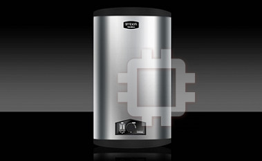
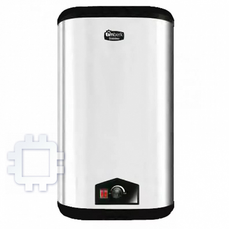
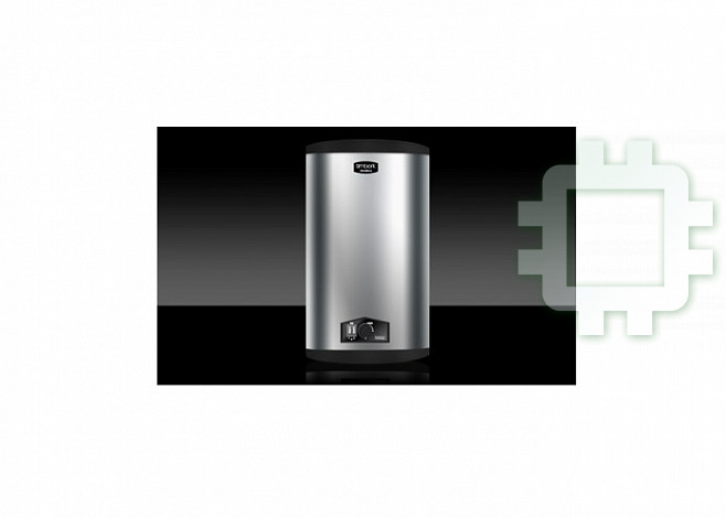
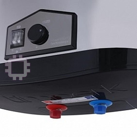
Timberk SWH FS3 50 V: инструкция
Раздел: Климат
Тип: Водонагреватель Накопительный
Характеристики, спецификации
Инструкция к Водонагревателю Накопительному Timberk SWH FS3 50 V
User Manual
iNUKE
NU6000DSP/NU3000DSP/NU1000DSP
Ultra-Lightweight, High-Density 6000/3000/1000-Watt Power
Amplier with DSP Control and USB Interface

2 iNUKE NU6000DSP/NU3000DSP/NU1000DSP User Manual
Table of Contents
Thank you .......................................................................2
Important Safety Instructions ...................................... 3
Legal Disclaimer ............................................................. 3
Limited Warranty ........................................................... 3
1. Introduction ............................................................... 5
1.1 Before you get started ...................................................... 5
2. Control Elements ....................................................... 5
2.1 Front panel ............................................................................ 5
2.2 Rear panel ............................................................................. 6
3. DSP Processor ............................................................ 6
3.1 Processor Functionality .................................................... 6
3.2 Front Panel control ............................................................ 6
3.3 BEHRINGER Amp Remote Software ........................... 10
4. Applications ............................................................. 16
4.1 Bi-amping ............................................................................ 16
5. Installation ............................................................... 18
5.1 Rack mounting ................................................................... 18
5.2 Connections ....................................................................... 18
6. Specications ........................................................... 19
Thank you
Thank you for choosing a BEHRINGER iNUKE DSP power amplier. This piece of
high-end gear was developed for professional use in live applications, and this
amplier incorporates many ground-breaking features that will make it a useful,
dependable, and exible part of your sound system.
The iNUKE DSP amps feature an onboard Digital Signal Processor for precise,
customized control. Multiple routing options, from dual mono to bridged
operation, to special functions dedicated to bi-amping applications, give this
amplier unprecedented exibility. Even better, all of these functions can be
controlled remotely from a PC via the downloadable BEHRINGER Amp Remote
control software.
This manual rst describes the panel controls and connection points before
delving into the DSP functionality. Special sections describe how you can
program the DSP by using either the amp's front panel controls, or by using the
Amp Remote software.
Read this manual and have fun as you become an iNUKE DSP Power User!
3 iNUKE NU6000DSP/NU3000DSP/NU1000DSP User Manual
Terminals marked with this symbol carry
electrical current of su cient magnitude
to constitute risk of electric shock.
Use only high-quality professional speaker cables with
¼" TS or twist-locking plugs pre-installed. Allother
installation or modi cation should be performed only
by quali edpersonnel.
This symbol, wherever it appears,
alertsyou to the presence of uninsulated
dangerous voltage inside the
enclosure-voltage that may be su cient to constitute a
risk ofshock.
This symbol, wherever it appears,
alertsyou to important operating and
maintenance instructions in the
accompanying literature. Please read the manual.
Caution
To reduce the risk of electric shock, donot
remove the top cover (or the rear section).
No user serviceable parts inside. Refer servicing to
quali ed personnel.
Caution
To reduce the risk of re or electric shock,
do not expose this appliance to rain and
moisture. The apparatus shall not be exposed to dripping
or splashing liquids and no objects lled with liquids,
suchas vases, shall be placed on the apparatus.
Caution
These service instructions are for use
by quali ed service personnel only.
Toreduce the risk of electric shock do not perform any
servicing other than that contained in the operation
instructions. Repairs have to be performed by quali ed
servicepersonnel.
1. Read these instructions.
2. Keep these instructions.
3. Heed all warnings.
4. Follow all instructions.
5. Do not use this apparatus near water.
6. Clean only with dry cloth.
7. Do not block any ventilation openings. Install in
accordance with the manufacturer’s instructions.
8. Do not install near any heat sources such as
radiators, heat registers, stoves, or other apparatus
(including ampli ers) that produce heat.
9. Do not defeat the safety purpose of the polarized
or grounding-type plug. A polarized plug has two blades
with one wider than the other. A grounding-type plug
has two blades and a third grounding prong. The wide
blade or the third prong are provided for your safety. Ifthe
provided plug does not t into your outlet, consult an
electrician for replacement of the obsolete outlet.
10. Protect the power cord from being walked on or
pinched particularly at plugs, convenience receptacles,
and the point where they exit from the apparatus.
11. Use only attachments/accessories speci ed by
themanufacturer.
12. Use only with the
cart, stand, tripod, bracket,
or table speci ed by the
manufacturer, orsold with
the apparatus. When a cart
is used, use caution when
moving the cart/apparatus
combination to avoid
injury from tip-over.
13. Unplug this apparatus during lightning storms or
when unused for long periods of time.
14. Refer all servicing to quali ed service personnel.
Servicing is required when the apparatus has been
damaged in any way, such as power supply cord or plug
is damaged, liquid has been spilled or objects have fallen
into the apparatus, the apparatus has been exposed
to rain or moisture, does not operate normally, or has
beendropped.
15. The apparatus shall be connected to a MAINS socket
outlet with a protective earthing connection.
16. Where the MAINS plug or an appliance coupler is
used as the disconnect device, the disconnect device shall
remain readily operable.
TECHNICAL SPECIFICATIONS AND APPEARANCES
ARE SUBJECT TO CHANGE WITHOUT NOTICE AND
ACCURACY IS NOT GUARANTEED. BEHRINGER IS
PART OF THE MUSIC GROUP MUSICGROUP.COM.
ALL TRADEMARKS ARE THE PROPERTY OF THEIR
RESPECTIVE OWNERS. MUSICGROUP ACCEPTS NO
LIABILITY FOR ANY LOSS WHICH MAY BE SUFFERED
BY ANY PERSON WHO RELIES EITHER WHOLLY OR
IN PART UPON ANY DESCRIPTION, PHOTOGRAPH
OR STATEMENT CONTAINED HEREIN. COLORS AND
SPECIFICATIONS MAY VARY FROM ACTUAL PRODUCT.
MUSIC GROUP PRODUCTS ARE SOLD THROUGH
AUTHORIZED FULLFILLERS AND RESELLERS ONLY.
FULLFILLERSAND RESELLERS ARE NOT AGENTS OF
MUSICGROUP AND HAVE ABSOLUTELY NO AUTHORITY
TO BIND MUSICGROUP BY ANY EXPRESS OR IMPLIED
UNDERTAKING OR REPRESENTATION. THIS MANUAL
Important Safety
Important Safety
IS COPYRIGHTED. NO PART OF THIS MANUAL MAY
Instructions
Instructions
BE REPRODUCED OR TRANSMITTED IN ANY FORM
OR BY ANY MEANS, ELECTRONIC OR MECHANICAL,
INCLUDING PHOTOCOPYING AND RECORDING OF ANY
KIND, FOR ANY PURPOSE, WITHOUT THE EXPRESS
WRITTEN PERMISSION OF MUSICGROUPIPLTD.
ALL RIGHTS RESERVED.
© 2012 MUSICGroupIPLtd.
Trident Chambers, Wickhams Cay, P.O. Box 146,
Road Town, Tortola, British Virgin Islands
LIMITED WARRANTY
For the applicable warranty terms and conditions
and additional information regarding MUSIC Group’s
Limited Warranty, please see complete details online at
www.music-group.com/warranty.
LEGAL DISCLAIMER
4 iNUKE NU6000DSP/NU3000DSP/NU1000DSP User Manual
(1) (3) (4) (7)
(2) (5)
(6) (8) (9)
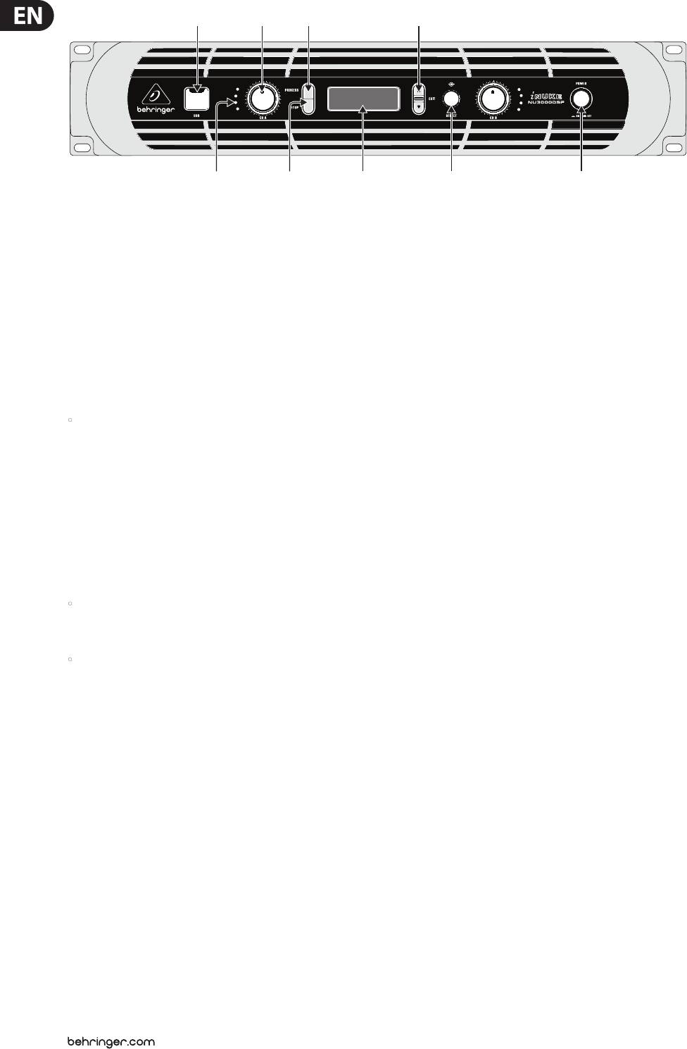
Front panel control elements
1. Introduction
Should your BEHRINGER product malfunction, it is our intention to have it
repaired as quickly as possible. To arrange for warranty service, please contact
1.1 Before you get started
the BEHRINGER retailer from whom the equipment was purchased. Should
your BEHRINGER dealer not be located in your vicinity, youmay directly contact
1.1.1 Shipment
one of our subsidiaries. Corresponding contact information is included in the
original equipment packaging (Global Contact Information/European Contact
Your iNUKE amplier was carefully packed at the factory, and the packaging is
Information). Shouldyour country not be listed, please contact the distributor
designed to protect the unit from rough handling. Nevertheless, we recommend
nearest you. A list of distributors can be found in the support area of our website
that you carefully examine the packaging and its contents for any signs of
(http://behringer.com).
physical damage that may have occurred during transit.
Registering your purchase and equipment with us helps us process your repair
• If the unit is damaged, please do NOT return it to BEHRINGER, but notify
claims more quickly and eciently.
your dealer and the shipping company immediately. Otherwise, claims for
damage or replacement may not be granted.
2. Control Elements
1.1.2 Initial operation
Please make sure the unit is provided with sucient ventilation, and never place
2.1 Front panel
your iNUKE amp on top of other heat-emanating equipment or in the vicinity of a
(1) USB connection enables rmware updates and control over parameters via
heater to avoid the risk of overheating.
computer. Please visit Behringer.com to download DSP control software for
The mains connection is made via the enclosed power cord and a standard IEC
your computer. The USB port is for amplier conguration only.
receptacle. It meets all international safety certication requirements.
(2) SIGNAL and LIMIT LEDs display the signal level for each channel. Reduce
• Please make sure that all units have a proper ground connection. For your
the input gain if the red LIMIT LED lights up continuously.
own safety, never remove or disable the ground conductor from the unit or
(3) CH A/CH B CONTROLS adjust the input level. To increase signal gain,
the AC power cord.
rotatethe knobs clockwise; to reduce the gain, rotate the knobs
• The sound quality may diminish within the range of powerful broadcasting
counter-clockwise.
stations and high-frequency sources. Increase the distance between the
(4) PROCESS button steps through the DSP processing modules.
transmitter and the device and use shielded cables for all connections.
(5) SETUP button steps through parameters within DSP processing modules.
1.1.3 Online registration
(6) LCD SCREEN displays the current DSP module and parameter settings.
Please register your new BEHRINGER equipment right after your purchase
(7) UP/DOWN/EXIT buttons step through DSP modules and parameters or exit
by visiting http://behringer.com and read the terms and conditions of our
to the top-level iNUKE screen (center button).
warrantycarefully.
(8) SELECT encoder knob toggles between Graphic and Edit modes
(when pressed) and changes parameter values (when rotated).
(9) POWER button turns the amplier on and o.
5 iNUKE NU6000DSP/NU3000DSP/NU1000DSP User Manual
(10)
(11)
(12) (13) (14)
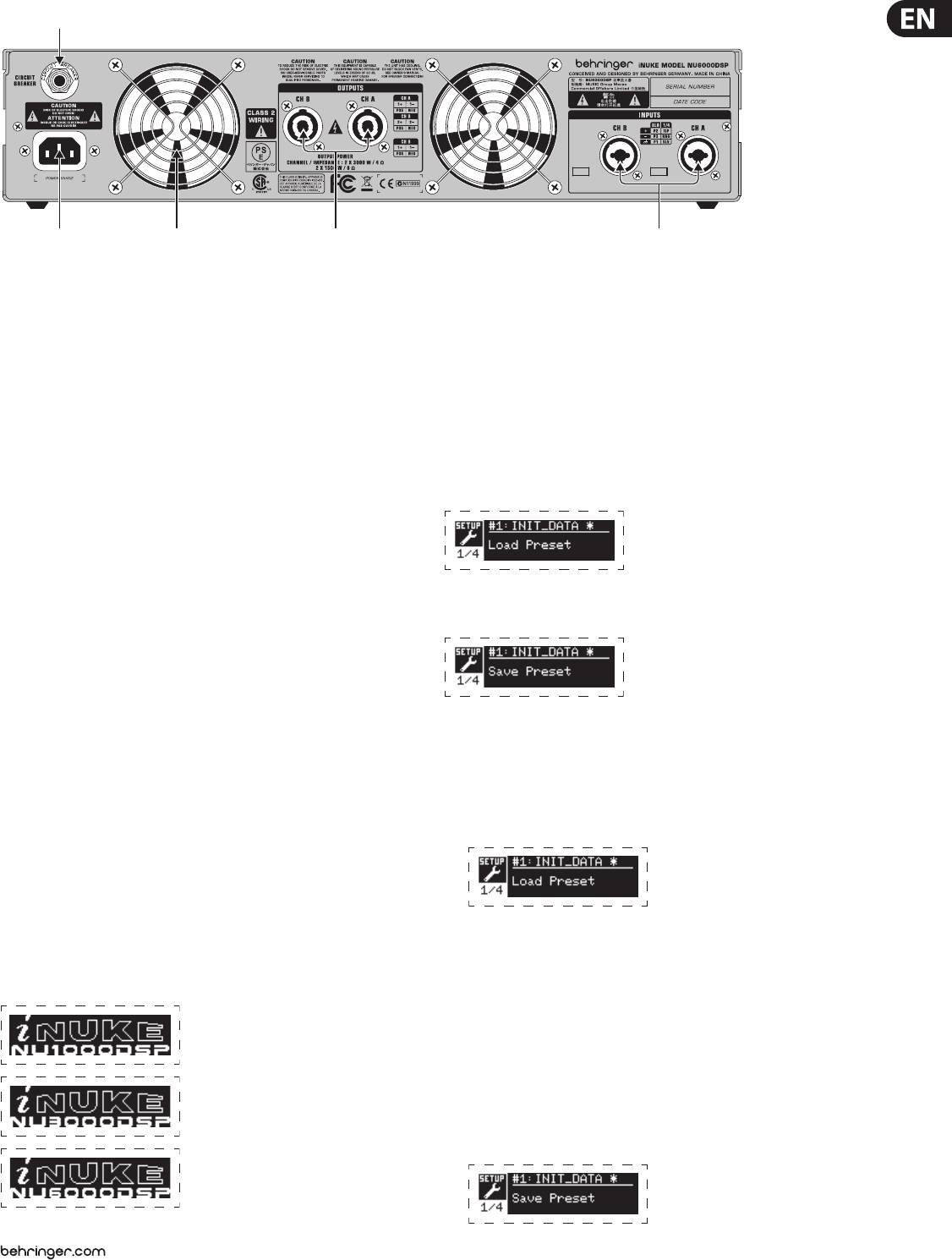
Rear panel control elements (NU6000DSP shown)
3.2.2 SETUP screens
2.2 Rear panel
The SETUP screens access the preset, panel lock, device naming, and LCD screen
(10) BREAKER (automated fuse, NU6000DSP only). After eliminating the cause of
contrast functions. To access these functions, press the SETUP button, and then
faulty operation, simply depress the BREAKER and power up the unit again.
move up and down through the top-level screens by pressing either the SETUP
The BREAKER acts in place of common discardable fuses.
button or the UP / DOWN arrow buttons.
(11) POWER SOURCE jack accepts the included IEC power cable.
(12) VENTILATION FAN speed adjusts automatically to ensure
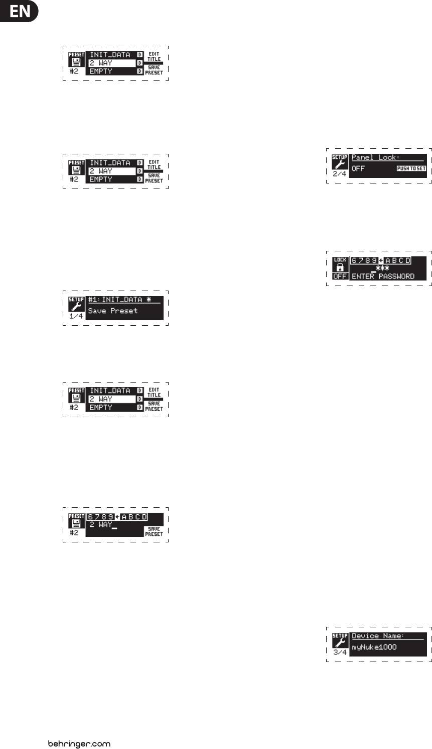
SETUP 1/4: Load Preset
trouble-free operation.
The top-level Load Preset screen displays the current Preset name
(13) TWIST- LOCKING SPEAKER OUTPUTS connect the amplier to the speakers
(up to 10 characters) and Preset number (1–20). Subsidiary screens oer
using professional speaker cables with twist-locking plugs.
options for loading, saving, and naming Presets.
(14) INPUTS route line-level input signals into these combination jacks using
XLR, balanced ¼" TRS, or unbalanced ¼" TS connectors.
3. DSP Processor
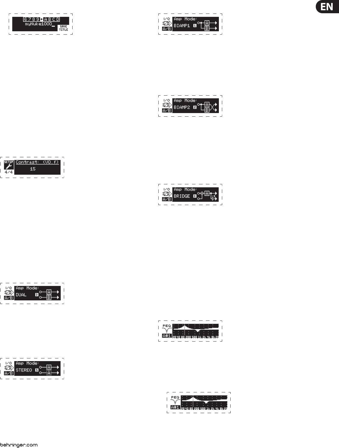
Below the Preset name, this screen displays the “Load Preset” option by default.
Rotate the SELECT encoder clockwise to access the “Save Preset” option.
3.1 Processor Functionality
The iNUKE DSP processor manipulates your signal in the digital domain, oering
tremendous exibility and control. You may control and program the DSP
processor via either the iNUKE amplier’s front panel or remotely by computer
using the BEHRINGER Amp Remote software (available for download from
Note: Preset #1:INIT_DATA cannot be overwritten. Select this preset any time
behringer.com).
you want to restore the amp's default settings.
By using the DSP processor, you can program all amplier functions and
parameters—except for the CH A and CH B input gain settings, which can only
Loading a Preset
be controlled using the CH A / CH B knobs on the amplier’s front panel.
1. Make sure the “Load Preset” option appears on the screen. (Rotate the
SELECT encoder to toggle between “Load Preset” and “Save Preset.”)
3.2 Front Panel control
The following material describes the DSP's screen organization and how to
program the processor's various functions by manipulating your iNUKE amplier's
front panel controls.
2. Press the SELECT encoder knob to access the DSP’s internal Preset list on the
3.2.1 Main top-level screen
next sub-screen. The correct sub-screen will display the LOAD PRESET option
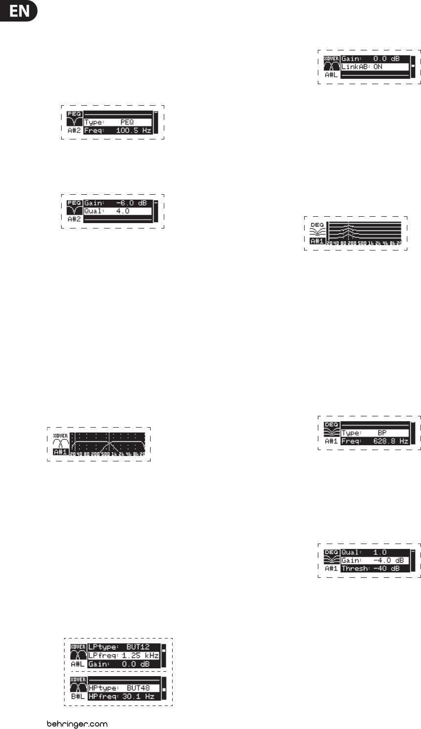
The top-level screen displays “iNUKE,” as well as the model name: NU1000DSP,
in the upper right-hand corner of the screen.
NU3000DSP, or NU6000DSP.
3. Scroll up and down through the Preset list by rotating the SELECT encoder knob.
As you scroll, the Preset number will appear to the left below the disk icon.
4. To load the selected Preset, you may either press the SELECT encoder or press
the UP arrow button.
Saving a preset
1. Make sure the “Save Preset” option appears on the screen. (Rotate the
SELECT encoder to toggle between “Load Preset” and “Save Preset.”)
6 iNUKE NU6000DSP/NU3000DSP/NU1000DSP User Manual
2. Press the SELECT encoder knob to access the DSP’s internal Preset list on the
SETUP 2/4: Panel Lock
next sub-screen. The correct sub-screen will display the EDIT TITLE and SAVE
The Panel Lock function uses a 4-character alphanumeric access code to lock
PRESET options on the right-hand side of the screen.
the front panel controls and prevent unauthorized changes to DSP settings.
Currentsettings can still be viewed while the unit is locked, but the parameters
cannot be changed.
The amplier can only be locked or unlocked from the Panel Lock screen.
3. Scroll through the list until you nd an EMPTY Preset slot or another Preset
Locking the amplier
you wish to overwrite.
1. Go to the Panel Lock screen by pressing the SETUP button.
4. If you wish to edit your Preset title before saving, press the UP arrow button
2. Press the SELECT encoder knob to access the password screen.
to choose the EDIT TITLE option.
3. Set an access code by using the SELECT encoder knob. Rotate the knob to
5. Edit the Preset title (see “Editing the Preset” title below).
scroll through the character list, and then select characters by pressing.
6. Select the SAVE PRESET option by pressing the DOWN arrow key.
With each press on the SELECT encoder knob, the password cursor will
advance left to right by one space.
Editing a Preset title
1. Make sure the “Save Preset” option appears on the screen. (Rotate the
SELECT encoder to toggle between “Load Preset” and “Save Preset.”)
4. The amplier will automatically lock when you select the nal character
for the access code. The display will ash a brief conrmation message:
“Device Locked!”
2. Press the SELECT encoder knob to access the DSP’s internal Preset list on the
5. The status displayed on the Panel Lock screen will state “LOCKED!”
next sub-screen. The correct sub-screen will display the EDIT TITLE and
SAVE PRESET options on the right-hand side of the screen.
Unlocking the amplier
1. Go to the Panel Lock screen by pressing the SETUP button.
2. Press the SELECT encoder knob to access the password screen.
3. Enter the access code by using the SELECT encoder knob. Rotate the knob
to scroll through the character list, and then select characters by pressing.
3. Scroll through the Preset list by rotating the SELECT encoder knob.
With each press on the SELECT encoder knob, the password cursor will
4. Select a Preset slot as a save destination by pressing the SELECT encoder knob.
advance left to right by one space.
5. Press the UP arrow button to select the EDIT TITLE function. The EDIT TITLE
4. The amplier will automatically unlock when you select the nal
window will appear, with alphanumeric characters in a row at the top and
character for the access code. The display will ash a brief conrmation
the current title directly below with the editing cursor.
message: “Unlocked.”
5. The status displayed on the Panel Lock screen will state “OFF.”
SETUP 3/4: Device Name
Each iNUKE DSP amplier can be individually named for easy identication
6. Select the backward arrow from the row of characters by rotating the
within a rack or remotely via the BEHRINGER Amp Remote control software
SELECT knob until the backward arrow is highlighted.
(go to Behringer.com to download the software).
7. Press the SELECT encoder knob to erase characters. The cursor will erase
Naming the amplier
characters from right to left across the existing title.
1. Access the Device Name screen by pressing the SETUP button.
8. Rotate the SELECT encoder to select new characters from the row above the
current Preset title.
9. Insert selected characters into the Preset title by pressing the SELECT
encoder knob. Once you select and insert a character, the editing cursor will
change direction and advance from left to right.
10. Save the new Preset title by pressing the DOWN arrow key to activate the
SAVE PRESET function.
7 iNUKE NU6000DSP/NU3000DSP/NU1000DSP User Manual
2. Press the SELECT encoder knob to access the editing screen.
BIAMP1
3. Choose the backwards arrow by turning the SELECT knob and press it to
BIAMP1 mode splits the Channel A input signal at a programmable frequency
delete the existing characters of the current preset name.
point, and then routes the resulting high and low frequency signals through
a parallel chain of DSP modules with independent equalization, signal delay,
4. Rotate the SELECT encoder to select new characters from the row above the
and limiter settings. In BIAMP1 mode, Output A routes low frequencies to a
current amplier name.
low-range speaker, while Output B connects to a high-frequency transducer.
5. Insert selected characters into the new amplier name by pressing the
SELECT encoder knob. Once you select and insert a character, the editing
BIAMP2
cursor will change direction and advance from left to right.
6. Save the new amplier name by pressing the DOWN arrow key to activate
the SAVE TITLE function.
SETUP 4/4: Contrast
BIAMP2 mode operates identically to BIAMP1 mode, except that the output
The Contrast screen allows you to adjust the LCD screen’s contrast level.
signals are swapped between Outputs A and B (i.e., Output B handles low
The Contrast parameter ranges from 1–30, with 30 representing maximum
frequencies while Output A handles high frequencies). The swapped A and B
contrast. Rotate the SELECT encoder knob to adjust the Contrast setting.
output routing allows the user to quickly correct reversed high/low speaker
connections without having to physically access the amplier’s back panel and
manually change the speaker connection.
BRIDGE
3.2.3 PROCESS screens
Pressing the PROCESS button opens up the various screens that determine the
signal path setup and that control processing parameters for the DSP modules:
I/O, PEQ, XOVER, DEQ, DELAY, and LIMIT.
BRIDGE mode combines the signals from Inputs A and B into a blended mono
You can move between top-level module screens by pressing the PROCESS button.
signal and then routes the resulting mono signal through a single chain of
DSP modules, leading to a combined mono output. The mono output signal is
I/O
identical at Outputs A and B, and the amplier responds to a single combined
speaker load.
The I/O module sets up the signal routing inside the DSP from input to output.
Press and rotate the SELECT encoder knob to choose between dual mono, stereo,
PEQ
bi-amped, or bridged routing options.
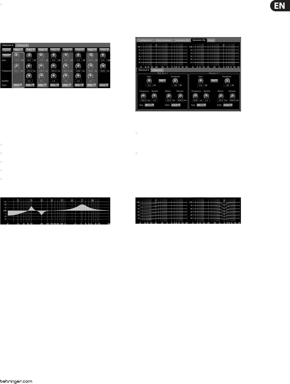
The PEQ module deploys up to eight EQ bands for precise sound sculpting.
DUAL
The EQ bands can each be switched between low shelving, high shelving,
and parametric modes. For the high shelving and low shelving EQ bands,
the LS12 and HS12 settings provide steeper equalization curves than the LS6 and
HS6 settings.
The main PEQ screen displays the composite equalization curve across the
frequency spectrum.
DUAL (dual mono) mode routes each channel input, A and B, through completely
separate parallel signal paths with independent outputs for each channel.
Each channel may be processed with its own unique lter, equalization,
signal delay, and limiter settings.
STEREO
Programming equalizers
1. Choose individual equalizers by rotating the SELECT encoder knob. As you
rotate the SELECT encoder knob, dotted vertical lines will appear at dierent
points within the frequency spectrum, and the EQ band name will appear in
the lower-left corner of the screen (e.g., A#1, A#2, B#1, B#2, and so on).
STEREO mode routes the signal from both the A and B inputs through a single
series of DSP modules. The parallel DSP modules process the A and B signals
with identical, linked settings (only module “A” parameter settings appear on
subsequent DSP module screens).
8 iNUKE NU6000DSP/NU3000DSP/NU1000DSP User Manual
2. Press the SELECT encoder knob to enter the parameter screens for your
5. Set the lter thresholds for high-pass (HPfreq) and low-pass (LPfreq) by
chosen EQ band.
rotating the SELECT encoder knob.
3. Press the UP / DOWN arrow keys to switch between parameters. The chosen
6. Set the lter’s overall signal gain (Gain) by rotating the SELECT encoder knob.
parameter will appear highlighted.
4. Rotate the SELECT encoder knob to change parameter values.
5. Choose the equalizer type (Type): OFF, PEQ (parametric), low shelving
(LS6, LS12), or high shelving (HS6, HS12).
7. Set the link parameter (LinkAB) to ON or OFF by rotating the SELECT encoder
knob (BIAMP1 and BIAMP2 modes only).
8. Press the SELECT encoder when nished to return to the top-level XOVER screen.
DEQ
6. Set the frequency (Freq) for each EQ band by rotating the SELECT encoder knob.
The programmed frequency can represent either the center frequency for
The DEQ module deploys a dynamic EQ that is triggered by a programmable
parametric mode, or the cuto frequency for low and high shelving modes.
signal thresold. For example, you can program the dynamic EQ to cut or boost
increasing amounts of mid frequencies as the signal gets louder beyond your
preferred threshold.
7. Set the EQ band’s cut or boost (Gain) by rotating the SELECT encoder knob.
8. For parametric mode, control the width of the parametric curve by tweaking
STEREO and BRIDGE modes feature one set of dynamic EQs (A#1 and A#2),
the Qual parameter. High Qual values produce a narrow, steep curve, while
while DUAL, BIAMP1, and BIAMP2 modes feature two sets of dynamic EQs
low Qual values create a wide curve with a gentle slope.
(A#1, A#2, B#1, and B#2). Each dynamic EQ may be set to OFF, band-pass (BP),
9. Press the SELECT encoder knob or the EXIT button to return to the top-level
low-pass (LP6, LP12), and high-pass (HP6, HP12).
PEQ screen.
Programming dynamic EQs
XOVER
1. Choose between dynamic EQ sets by rotating the SELECT encoder knob.
The XOVER module oers programmable pairs of high- and low-pass lters.
2. Press the SELECT encoder knob to enter the parameter screens.
STEREO and BRIDGE modes possess only one lter set (A#1). DUAL, BIAMP1,
and BIAMP2 modes use two lter sets (A#1 and B#1), and in BIAMP1 and BIAMP2
3. Move up or down between parameters by pressing the UP / DOWN
modes, these two sets of lters may be linked.
arrow buttons.
On the top-level screen, vertical dotted lines indicate the threshold point for
4. Choose between EQ types (Type) by rotating the SELECT encoder knob.
each lter.
5. Set the frequency (Freq) for each EQ by rotating the SELECT encoder knob.
Each low-pass and high-pass lter also oers multiple options for lter
The programmed frequency can represent either the center frequency for
type and slope: OFF, Butterworth (BUT6, BUT12, BUT18, BUT24, BUT48),
band-pass mode, or the threshold frequency for low- and high-pass modes.
Bessel (BES12, BES24), or Linkwitz-Riley (LR12, LR24, LR48).
6. For band-pass mode, control the width of the band-pass curve by tweaking
the Qual parameter. High Qual values produce a narrow, steep curve,
Programming lters/bi-amping crossover
while low Qual values create a wide curve with a gentle slope.
1. Choose between lter sets A#1 and B#1 by rotating the SELECT encoder knob
(DUAL, BIAMP1, and BIAMP2 modes only).
2. Press the SELECT encoder knob to enter the parameter screens.
3. Move up or down between parameters by pressing the UP / DOWN
arrow buttons.
7. Set the dynamic equalizer’s cut or boost (Gain) by rotating the SELECT
encoder knob.
4. Choose between lter types for high-pass (HPtype) and low-pass (LPtype)
by rotating the SELECT encoder knob.
8. Set the signal threshold (Thresh) by rotating the SELECT encoder knob.
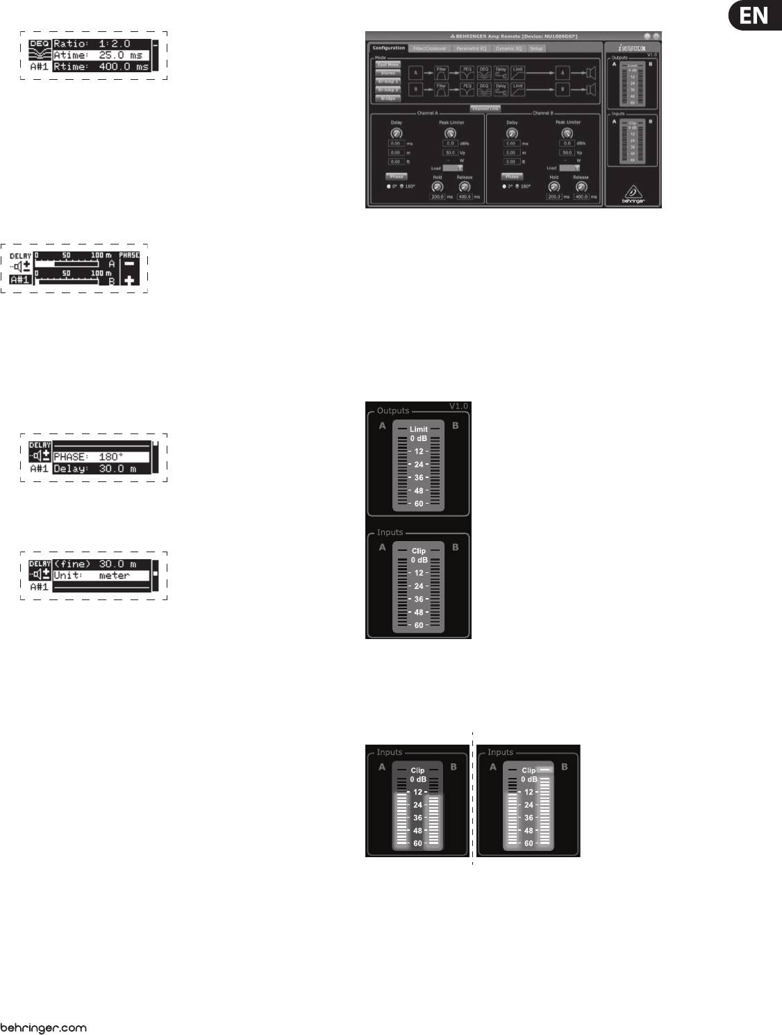
9. Program your desired ratio (Ratio). Similar to a compressor, higher ratio
values yield a more intense equalization eect.
9 iNUKE NU6000DSP/NU3000DSP/NU1000DSP User Manual
10. Adjust attack (Atime) and release (Rtime) to your preferred values.
3.3 BEHRINGER Amp Remote Software
11. Press the SELECT encoder when nished to return to the top-level DEQ screen.
DELAY
The DELAY DSP module digitally slows the nal signal output from the amplier by a
programmable amount (expressed as either distance or time). This signal delay helps
prevent phase and synchronization problems caused by sound traveling through air
over long distances, e.g., between speaker arrays separated by long distances or
between a performance stage and distant sound reinforcement speakers.
The BEHRINGER Amp Remote software allows the user to control all iNUKE DSP
settings remotely from a computer via the USB connection located on the iNUKE
front panel.
3.3.1 METERS
Programming signal delay
Meters
1. Choose between signal paths (A#1, B#1) by rotating the SELECT encoder knob.
Monitor input and output levels by using the virtual meters on the right hand
2. Press the SELECT encoder knob to enter the parameter screens.
side of the control software screen. Adjust input levels using the knobs on the
amplier’s front panel.
3. Move up or down between parameters by pressing the UP / DOWN arrow buttons.
4. Choose between 0° and 180° phase (PHASE) by rotating the SELECT encoder knob.
5. Choose your amount of signal delay (Delay) by rotating the SELECT encoder button.
6. Fine tune the Delay value using the (ne) parameter.
7. Change the delay’s unit of measure (Unit), if necessary, by rotating the
SELECT encoder knob. The delay value can be expressed in milliseconds (ms),
meters (m), or feet (ft).
The Amp Remote software displays two level meters, one for the input signal,
8. Press the SELECT encoder when nished to return to the top-level DELAY screen.
and another meter for the nal output signal.
LIMIT
Input Meters
The LIMIT DSP module controls the unit’s output limiter, with programmable
parameters for threshold (Thresh), release (Rtime), and hold (Hold).
The top-level LIMIT screen always displays the threshold (Thresh) setting for
quick reference.
Programming the output limiter
1. Choose between signal paths (A#1, B#1) by rotating the SELECT encoder knob.
2. Press the SELECT encoder knob to enter the parameter screens.
The input meters show the signal level at the CH A and CH B inputs. If the input
3. Move up or down between parameters by pressing the UP / DOWN
signal exceeds the 0 dB level, the red Clip indicator will light over the channel
arrow buttons.
experiencing an overload.
4. Choose a threshold (Thres) setting by rotating the SELECT encoder knob.
The input level can only be controlled by using the CH A and CH B knobs on the
5. Choose a release time (Rtime) by rotating the SELECT encoder knob.
front panel of the iNUKE amplier. The Amp Remote software does not control
the input level.
6. Choose a hold (Hold) setting by rotating the SELECT encoder knob.
7. Press the SELECT encoder when nished to return to the top-level LIMIT screen.
10 iNUKE NU6000DSP/NU3000DSP/NU1000DSP User Manual
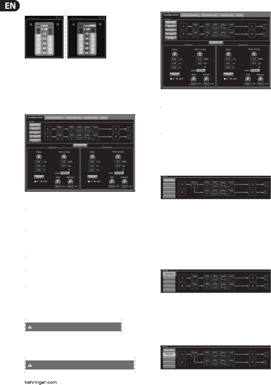
Output Meters
3.3.4 Conguration
The output meters show the signal level at the end of the DSP signal chain,
following the Limit module. If the signal activates the limiter, the red Limit
indicator will light over the channel experiencing an overload.
3.3.2 Function Tabs
The Conguration tab displays two main sets of software controls:
The BEHRINGER Amp Remote window allows the user to access DSP functions via
embedded tabs accessible near the top of the software window.
• Mode—controls the amplier conguration. Choose between Dual Mono,
Stereo, Bi-Amp 1, Bi-Amp 2, and Bridge congurations. Each conguration’s
complete signal path appears in the display window, including the
arrangement of internal DSP modules and speaker outputs.
• Delay/Peak Limiter—controls settings for the Delay and Limit DSP
modules, as well as options for channel phase, Load settings (in Ohms) for
the limiter wattage display, Hold and Release for the Limiter, and channel
linking. The number of Delay/Peak Limiter controls change depending on the
amplier Mode conguration.
Mode
The software window includes these tabbed screens:
Changing amplier mode
• Conguration—controls the amplier Mode setting for Dual Mono,
Stereo, and other routing options, as well setting controls for output delay
The amplier mode can be changed by clicking on the button for your desired
and limiting.
routing option along the left-hand side of the window. When you click on a
mode button, the software will launch a conrmation window. Click “Yes” in the
• Filter/Crossover—oers control over adjustable hi-pass and lo-pass
conrmation window to launch the new amplier mode, and the new signal path
lters. In Bi-Amp 1 and Bi-Amp 2 conguration, this tab controls the
will appear in the display.
crossover point for splitting the blended, mono input signal into separate
high- and low-frequency mono signals for bi-amping.
Mode descriptions
• Parametric EQ—controls up to 8 adjustable parametric and shelving EQs
for each channel.
Dual Mono
• Dynamic EQ—adjusts parameters for 2 bands of level-dependent, dynamic
equalization per channel.
• Setup—manages presets and networking options.
3.3.3 Connection Status
Dual Mono mode routes each channel input, A and B, through completely
The software displays the connection status in the top header of the main
separate parallel signal paths with independent outputs for each channel.
software window.
Each channel may be processed with its own unique lter, equalization, delay,
and limiter settings. The Delay and Limit modules for A and B can be linked and
programmed with identical settings by clicking on the Channel Link button
BEHRINGER Amp Remote [not connected!]
below the Mode window.
Stereo
When the amp/software connection is active, the window heading displays the
name of the amplier.
BEHRINGER Amp Remote [Device: NU1000DSP!]
Stereo
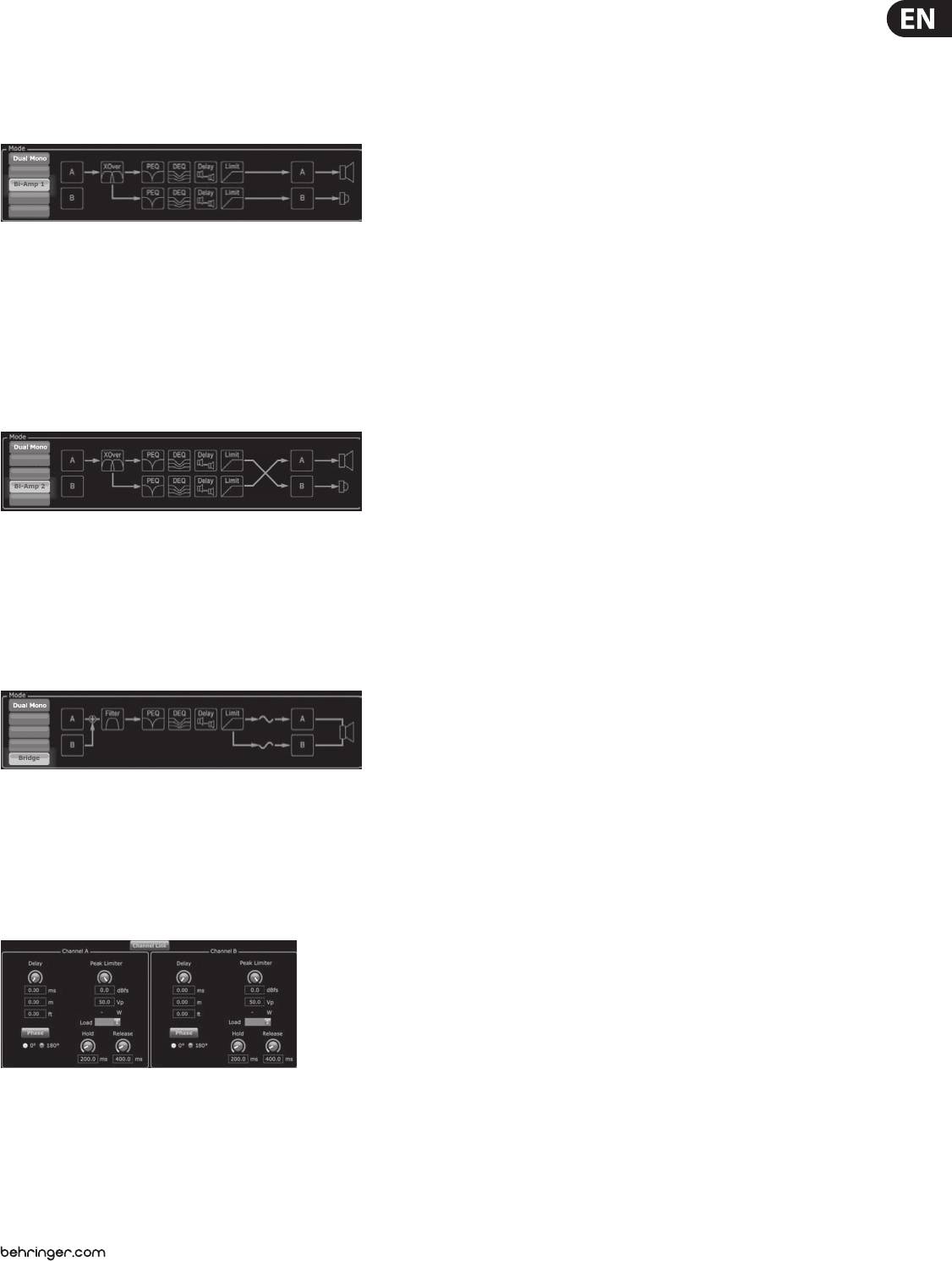
Bi-Amp 1
Bi-Amp 2
Bridge
Stereo
Bi-Amp 1
Bi-Amp 2
Bridge
Stereo
Bi-Amp 1
Bi-Amp 2
Bridge
11 iNUKE NU6000DSP/NU3000DSP/NU1000DSP User Manual
Stereo mode routes the signal from both the A and B inputs through a single
Delay
series of DSP modules. Each DSP module processes both the A and B signals
The Delay function digitally slows the nal signal output from the amplier by a
with identical, linked settings. The linked Delay and Limit parameters can be
programmable amount (expressed as either distance or time). This signal delay helps
controlled from Stereo mode’s consolidated Channel A+B control window
prevent phase and synchronization problems caused by sound traveling through
(which displays automatically when Stereo mode is selected).
air over long distances, e.g., between speaker arrays separated by long distances or
Bi-Amp 1
between a performance stage and distant sound reinforcement speakers.
The Delay controls also simultaneously display the amount of signal delay in
Stereo
milliseconds (ms), meters (m), and feet (ft), which can be useful if you already
Bi-Amp 1
know the precise distance between speakers.
Bi-Amp 2
Bridge
Programming signal delay
Bi-Amp 1 mode splits the Channel A input signal in the XOver DSP module at
1. Program the signal delay by using either of these two methods:
a programmable frequency point, and then routes the resulting high and low
frequency signals through a parallel chain of DSP modules with independent
a) Rotate the Delay virtual knob clockwise until you achieve a suitable amount
equalization, delay, and limiter settings. The Delay and Limit modules for the split
of signal delay. The ms, m, and ft text boxes will each display equivalent
high and low frequency signals can be linked and programmed with identical
values as you rotate the virtual knob.
settings by clicking on the Channel Link button below the Mode window. In
b) Type a delay value directly into one of the text boxes below the Delay virtual
Bi-Amp 1 mode, Output A routes low frequencies to a low-range speaker, while
knob (ms, m, or ft, depending on your preference). The Delay virtual knob
Output B connects to a high-frequency transducer.
will rotate to a position matching the delay value you have entered.
Bi-Amp 2
2. Choose between 0° and 180° phase either by clicking on the Phase virtual
button or by clicking directly on 0° or 180° directly below the virtual button.
When the Phase virtual button is engaged, the virtual button will light
yellow and the indicator next to 180° will light up.
Peak Limiter
Bi-Amp 2 mode operates identically to Bi-Amp 1 mode, except that the signals
The Peak Limiter helps protect your speakers by preventing signal spikes at the
are swapped between Outputs A and B (i.e., Output B handles low frequencies
amplier's output stage.
while Output A handles high frequencies). The swapped A and B output routing
The Peak Limiter controls include a dedicated virtual knob with matching
allows the user to quickly correct reversed high/low speaker connections without
numerical displays in dBfs (decibels relative to full scale), Vp (Voltage(peak)),
having to physically access the amplier’s back panel and manually change the
as well as a rating in Watts, which appears only when you choose an Ohm setting
speaker connection.
from the Load pulldown menu.
Bridge
The BEHRINGER Amp Remote software also allows you to see the amplier's total
output as a rating in Watts. This Watt rating allows you to connect speakers with
lower power ratings and then adjust the limiter to match the speakers' maximum
Watt rating.
Note: the Amp Remote software does not automatically detect or show the total
speaker load connected to the amplier.
Bridge mode combines the signals from Inputs A and B into a blended mono
Controls for Hold and Release times appear near the bottom of the window, each
signal and then routes the resulting mono signal through a single chain of
with a matching numerical display.
DSP modules, leading to a combined mono output. The mono output signal is
identical at Outputs A and B, and the amplier responds to a single combined
Programming the output limiter
speaker load.
1. Program the output limiter by using either of these two methods:
Delay/Peak Limiter
a) Rotate the Peak Limiter virtual knob counter-clockwise until you nd an
adequate limiter setting for your sound system. The dBfs (decibels relative
to full scale) and Vp (Voltage [peak]) text boxes will each display equivalent
values as you rotate the virtual knob.
b) Type a limiter value directly into one of the text boxes below the Peak
Limiter virtual knob (dBfs or Vp). The Peak Limiter virtual knob will rotate to
a position matching the delay value you have entered.
2. Choose a Load value from the Load pulldown menu (none, 2, 4, 8, or 16 Ohms)
Channel Link
that matches the total combined load of all speakers connected to the
amplier's outputs. If your combined speaker load in Ohms does not exactly
In Dual Mono, Bi-Amp 1, and Bi-Amp 2 modes, the Channel Link virtual button
match 2, 4, 8, or 16 Ohms, choose the next lower Ohm setting from the Load
will appear just above the Delay and Peak Limiter controls. When you click on
pulldown menu (i.e., if your total combined speaker load equals 4.25 Ohms,
the Channel Link virtual button, the button will light up, and the Delay and Peak
select the 4 Ohm setting). When you select a Load setting, an additional Watt
Limiter controls for both channels will display identical values.
rating for the limiter will appear above the Load pulldown menu.
Stereo
Bi-Amp 1
Bi-Amp 2
Bridge
Stereo
Bi-Amp 1
Bi-Amp 2
Bridge
12 iNUKE NU6000DSP/NU3000DSP/NU1000DSP User Manual
3. Choose a Hold value either by rotating the Hold virtual knob or by entering a
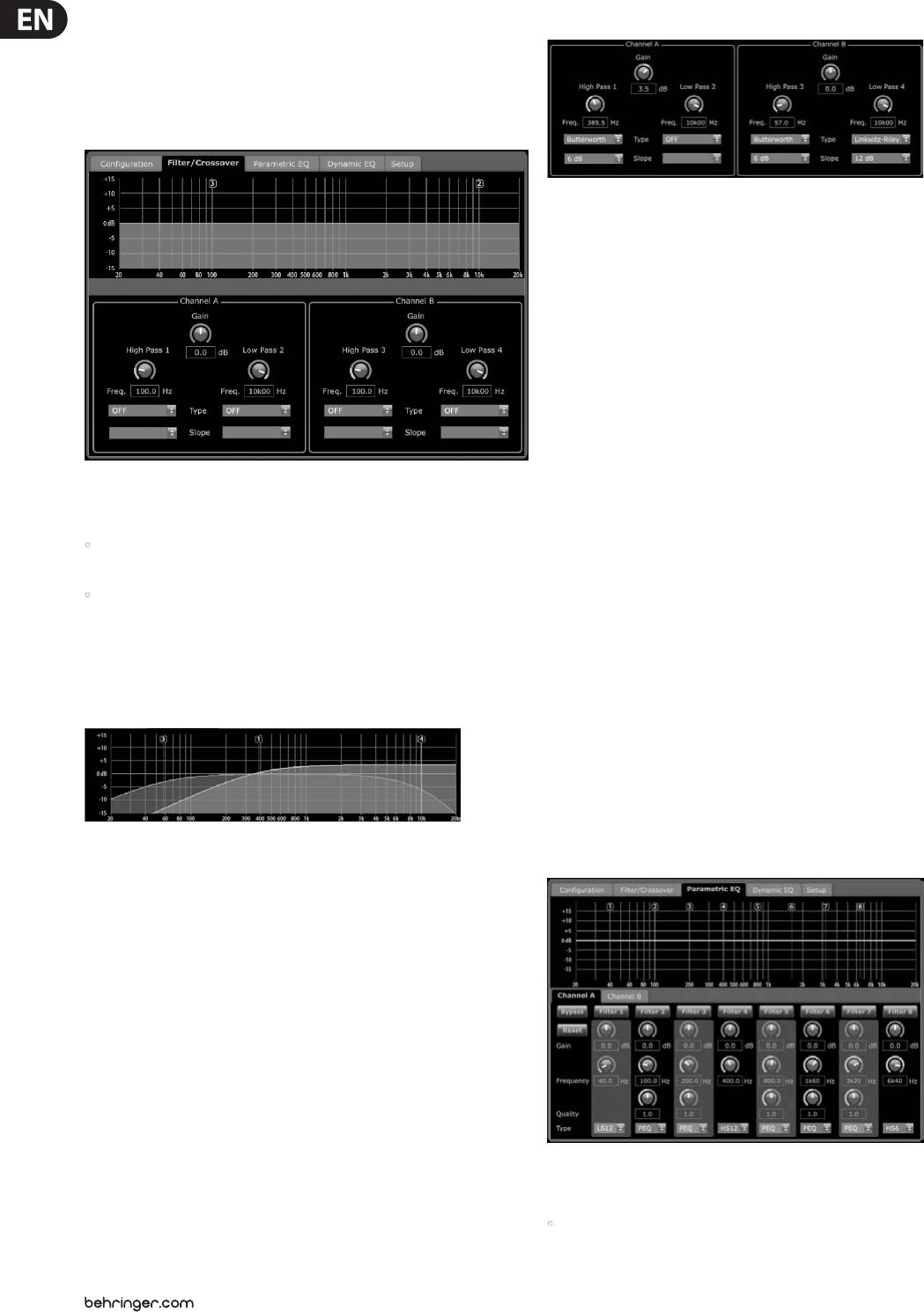
Filter/Crossover Control View
value (in milliseconds) into the matching text box below the knob.
4. Choose a Release value either by rotating the Release virtual knob or by
entering a value (in milliseconds) into the matching text box below the knob.
3.3.5 Filter/Crossover
The Control View of the Filter/Crossover tab contains virtual knob controls for
Gain, High Pass lter, and Low Pass lter. Exact parameter values appear in boxes
below each virtual knob. These parameters may be altered by either adjusting
the virtual knobs or by entering values directly in the parameter boxes.
Pull-down menus contain lter options for Type (Butterworth, Bessel,
Linkwitz-Riley) and Slope (6–48 dB).
X-Over option for bi-amping
In Bi-Amp 1 and Bi-Amp 2 modes, the X-Over button appears on the Filter/
Crossover tab. Activating the X-Over button links the Low Pass 2 and High Pass
3 lter controls and automatically creates a synchronized crossover point for
bi-amped low frequency and high frequency signals.
Setting a linked crossover frequency
The Filter/Crossover tab displays and controls Filter/XOver module settings in
two formats:
1. Activate the Bi-Amp 1 or Bi-Amp 2 settings on the Conguration tab.
• Frequency Curve—displays the lter curves in visual form, and allows
2. Click on the Filter/Crossover tab.
click-and-drag manipulation of lter threshold points.
3. Click on the X-Over button on the Filter/Crossover tab. The X-Over button will
• Control View—allows parameter tweaks via virtual controls, as well as
light up and overlapping lter curves will appear in the Frequency Curve.
pull-down menus for lter type and slope.
4. Set the crossover frequency by any of these methods:
The Frequency Curve and Control View interact with each other and
a) drag the Low Pass 2/High Pass 3 threshold line to the desired frequency in
simultaneously shift as you change parameters in either view.
the Frequency Curve by clicking and dragging;
Filter/Crossover Frequency Curve Display
b) adjust the Low Pass 2 or High Pass 3 virtual knobs;
c) Enter the desired frequency directly into the Freq. text box.
5. Select a lter curve from the Type dropdown menu below either the Low
Pass 2 or High Pass 3 virtual knobs.
6. Select the desired curve steepness from the Slope dropdown menu.
The Frequency Curve displays a frequency range from 20 Hz to 20 kHz, with 15 dB of
3.3.6 Parametric EQ
cut/boost displayed on the vertical axis. Within this graphic eld, the lter curve
appears as a solid, colored line running from left to right. The line shifts and
moves to reect changing parameter values entered using the virtual controls and
pull-down menus. Dotted vertical lines indicate frequency threshold points for the
various lters, numbered 1 through 4, and these threshold points can be selected
and moved through the frequency spectrum using the mouse or trackpad.
Moving lter thresholds via click-and-drag
1. Click and hold on the numbered box at the top of the desired lter threshold line.
2. Drag the threshold line to the desired location on the frequency spectrum.
3. The lter curve shown by the solid line will move and adjust as you shift
the threshold line. The virtual knob and frequency displayed in the Control
View will also simultaneously change as you move the threshold line in the
Frequency Curve.
The Parametric EQ tab displays and controls PEQ DSP module settings in two
formats (similar to the Filter/Crossover tab):
• Control View—allows parameter tweaks via virtual controls, as well as
pull-down menus for EQ type (parametric, low shelving, and high shelving).
13 iNUKE NU6000DSP/NU3000DSP/NU1000DSP User Manual
• Frequency Curve—displays the lter curves in visual form, and allows
3. The EQ curve shown by the solid yellow ll will re-size and adjust as you
click-and-drag manipulation of EQ frequencies and gain.
move the cursor up and down the frequency line. The virtual gain knob and
gain dB displayed in the Control View will also simultaneously change as you
The Frequency Curve and Control View interact with each other and
move the cursor up and down frequency line in the Frequency Curve.
simultaneously shift as you change parameters in either view.
4. Dynamic EQ
Parametric EQ Control View
The Control View of the Parametric EQ tab contains virtual knob controls for Gain,
Frequency, Quality (parametric EQ only). Exact parameter values appear in boxes
below each virtual knob. These parameters may be altered by either adjusting
the virtual knobs or by entering values directly in the parameter boxes.
The Dynamic EQ tab displays and controls DEQ DSP module settings in two
To activate an EQ band, click the button (Filter 1, Filter 2, and so on) at the top of
formats (similar to the Filter/Crossover and Parametric EQ tabs):
each channel strip. The channel button will light up to indicate the EQ is active.
• Frequency Curve—displays the layered dynamic EQ curves in visual form,
Pull-down Type menus for each EQ band contain these additional options:
and allows click-and-drag manipulation of dynamic EQ/lter frequencies
• PEQ (parametric EQ)
and gain.
• LS6 (low shelving EQ, with a 6 dB slope)
• Control View—allows parameter tweaks via virtual controls, as well
as pull-down menus for EQ/lter type (Type) and gain reduction/boost
• LS12 (low shelving EQ, with a 12 dB slope)
ratio (Ratio).
• HS6 (high shelving EQ, with a 6 dB slope)
The Frequency Curve and Control View interact with each other and
• HS12 (high shelving EQ, with a 12 dB slope)
simultaneously shift as you change parameters in either view.
Parametric EQ Frequency Curve Display
Dynamic EQ Frequency Curve Display
The Frequency Curve displays a frequency range from 20 Hz to 20 kHz, with 15 dB
The Frequency Curve displays a frequency range from 20 Hz to 20 kHz, with
of cut/boost displayed on the vertical axis. Within this graphic eld, the EQ curve
layered dynamic EQ curves. Within this graphic eld, the dynamic EQ curves
appears as a solid ll above and below the 0 dB center line and running from
appear as solid yellow lines that appear at every 10 dB (0 to -50 dB) threshold on
left to right. The curve shifts and moves to reect changing parameter values.
the vertical axis. The curves shift and move to reect changing parameter values.
Dotted vertical lines indicate frequency points for the various EQ bands,
Dotted vertical lines indicate frequency points for the various dynamic EQ bands,
numbered 1 through 8, and these frequency points can be selected and moved
numbered 1 and 2 (per channel), and these frequency points can be selected and
through the frequency spectrum using the mouse or trackpad. The gain for each
moved through the frequency spectrum using the mouse or trackpad. The gain
EQ band may also be adjusted by using the frequency lines.
for each dynamic EQ band may also be adjusted by using the frequency lines.
Adjusting Parametric EQ frequency via click-and-drag
Adjusting dynamic EQ frequency via click-and-drag
1. Click and hold on the numbered box at the top of the desired EQ band
1. Click and hold on the numbered box at the top of the desired dynamic
frequency line.
EQ band frequency line.
2. Drag the frequency line to the desired location on the frequency spectrum.
2. Drag the frequency line to the desired location on the frequency spectrum.
3. The EQ curve shown by the solid yellow ll will move and adjust as you shift
3. The layered dynamic EQ curves shown by the layered yellow lines will move
the frequency line. The virtual knob and frequency displayed in the Control
and adjust as you shift the frequency line. The virtual knob and frequency
View will also simultaneously change as you move the frequency line in the
displayed in the Control View will also simultaneously change as you move
Frequency Curve.
the frequency line in the Frequency Curve.
Adjusting Parametric EQ gain via click-and-drag
1. Click and hold over the numbered box at the top of the desired EQ band’s
frequency line.
2. Move the cursor vertically up or down the frequency line to the desired gain level.
14 iNUKE NU6000DSP/NU3000DSP/NU1000DSP User Manual
Adjusting dynamic EQ gain via click-and-drag
6. Program your desired ratio by selecting from the Ratio pulldown menu.
Similar to a compressor, higher ratio values yield a more intense
1. Click and hold on the numbered box at the top of the desired dynamic
equalization eect.
EQ band frequency line.
7. Adjust the attack (Attack) and release (Release) values by rotating each
2. Move the cursor vertically up or down the frequency line to the desired
parameters respective virtual knob.
gain level.
3. The layered EQ curves shown by the solid yellow line will adjust as you move
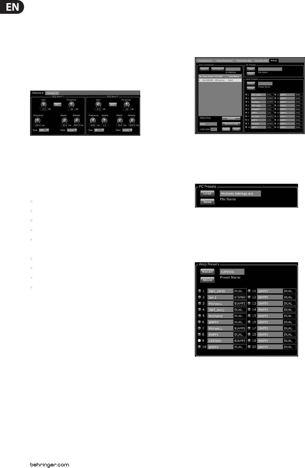
3.3.7 Setup
the cursor up and down the frequency line. The virtual gain knob and gain
dB displayed in the Control View will also simultaneously change as you
move the cursor up and down frequency line in the Frequency Curve.
Dynamic EQ Control View
The Setup tab allows you to manage connections and settings for your
The Control View of the Dynamic EQ tab contains virtual knob controls for Gain,
iNUKE amps. Amp presets may be stored either on the iNUKE DSP or on the PC
Threshold, Frequency, Quality (bandpass lter only). Exact parameter values
(presets stored on your PC may then be loaded onto any iNUKE amplier).
appear in boxes below each virtual knob. These parameters may be altered
by either adjusting the virtual knobs or by entering values directly in the
parameter boxes.
PC Presets
Pull-down Type menus for each dynamic EQ band contain these
additional options:
• BP (bandpass lter)
• LP6 (lo-pass lter, with a 6 dB slope)
The PC Presets section allows you to store iNUKE DSP presets on your computer
• LP12 (lo-pass lter, with a 12 dB slope)
instead of the iNUKE amp’s internal memory. The Load function allows you to
• HP6 (hi-pass lter, with a 6 dB slope)
upload presets from the computer, while the Save function stores the current
• HP12 (hi-pass lter, with a 12 dB slope)
iNUKE DSP settings to the computer (these les use a .arp lename extension).
The Ratio pulldown menu oers four options:
Amp Presets
• 1:2.0
• 1:3.0
• 1:5.0
• 1:10
Gain vs. Ratio
Positive gain settings result in a frequency boost at low signal levels and a nearly
at EQ response at high levels. Negative gain settings yield opposite results: at
low signal levels, the EQ response is nearly at, while higher signal levels receive
increasing amounts of cut from the equalizer. The higher the Ratio setting, the
more the equalizer will cut or boost the signal at dierent signal levels.
Programming a dynamic EQ
1. Choose an EQ type from the Type pulldown menu.
The Amp Presets section allows you to access and manage presets stored in the
2. Set the dynamic EQ's band frequency by rotating the Frequency virtual knob.
iNUKE amp’s internal memory. The amp’s internal memory holds up to 20 presets,
The programmed frequency can represent either the center frequency for
and these 20 preset slots appear in the Amp Presets section as a numbered,
band-pass (BP) mode, or the threshold frequency for low- (LP) and high-pass
double-column list showing the preset name and the preset’s signal routing
modes (HP).
conguration (DUAL, STEREO, BIAMP1, and so on). The preset currently in use will
display an illuminated dot immediately to the preset’s left.
3. For band-pass BP mode, control the width of the band-pass curve by
rotating the Quality virtual knob parameter. High Qual values produce
Note: Preset #1:INIT_DATA cannot be overwritten. Select this preset any time
a narrow, steep curve, while low Qual values create a wide curve with a
you want to restore the amp's default settings.
gentle slope.
Recalling a preset stored in the amp’s internal memory
4. Set the dynamic EQ’s band cut or boost by rotating the Gain virtual knob.
1. Click on the desired preset in the Amp Presets list. The dot to the immediate
5. Set the signal threshold by rotating the Threshold knob.
left of the selected preset will light up.
15 iNUKE NU6000DSP/NU3000DSP/NU1000DSP User Manual
2. Click on the Recall button in the upper left of the Amp Presets section. The
Renaming an amplier
selected preset’s name will appear in the text box next to the Recall button.
1. Type the new amplier name directly into the text box to the left of the
All settings contained in the preset will automatically deploy.
Rename Amp virtual button near the bottom of the Amp Connection section.
Saving a preset to the amp’s internal memory
2. Click on the Rename Amp virtual button. The new amplier name will
appear in the Amp Name column of the amplier list.
1. Select a destination for the preset by clicking on a slot in the preset list.
(If you save your preset to a slot already holding a stored preset, the stored
Locking the amplier
preset will be replaced by your new preset.)
1. Type a 4-character lock code of your choosing directly into the Lock Code
2. Type your new preset’s name into the text box to the right of the Recall button.
window near the bottom of the Amp Connection section. (The Lock function
3. Click on the Store button to store your preset in the selected slot in the preset
requires a new lock code every time you lock the amplier.)
list. Your new preset’s name will appear in the selected slot in the preset list.
2. Click on the Lock virtual button at the bottom right of the Amp Connection
section. The Lock virtual button will turn red to indicate the amplier front
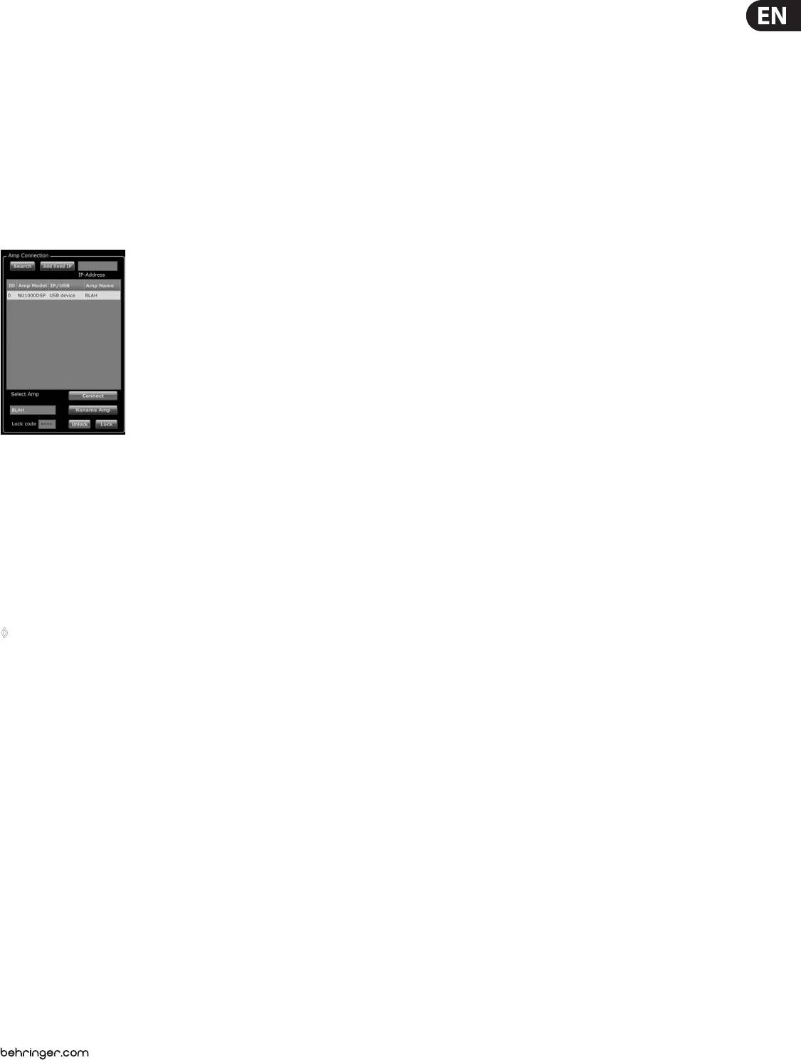
Amp Connection
panel has been locked.
3. Clear the 4-character code from the Lock Code window if you desire
extra security.
Unlocking the amplier
1. Type the amplier's 4-character lock code into the Lock Code window near
the bottom of the Amp Connection section.
2. Click on the Unlock virtual button located directly to the right of the Lock
Code text box. The Unlock virtual button will light up yellow to indicate the
amplier is unlocked, while the Lock button will change colors from red to
gray. The characters in the Lock Code text box will disappear and be replaced
by asterisks.
The Amp Connection section tells you which iNUKE amplier you have connected
to the software, as well as options for naming your iNUKE amp and for setting
4. Applications
up a code to lock the amplier's front panel and prevent tampering (the amp can
still be edited from your laptop using the Amp Remote software).
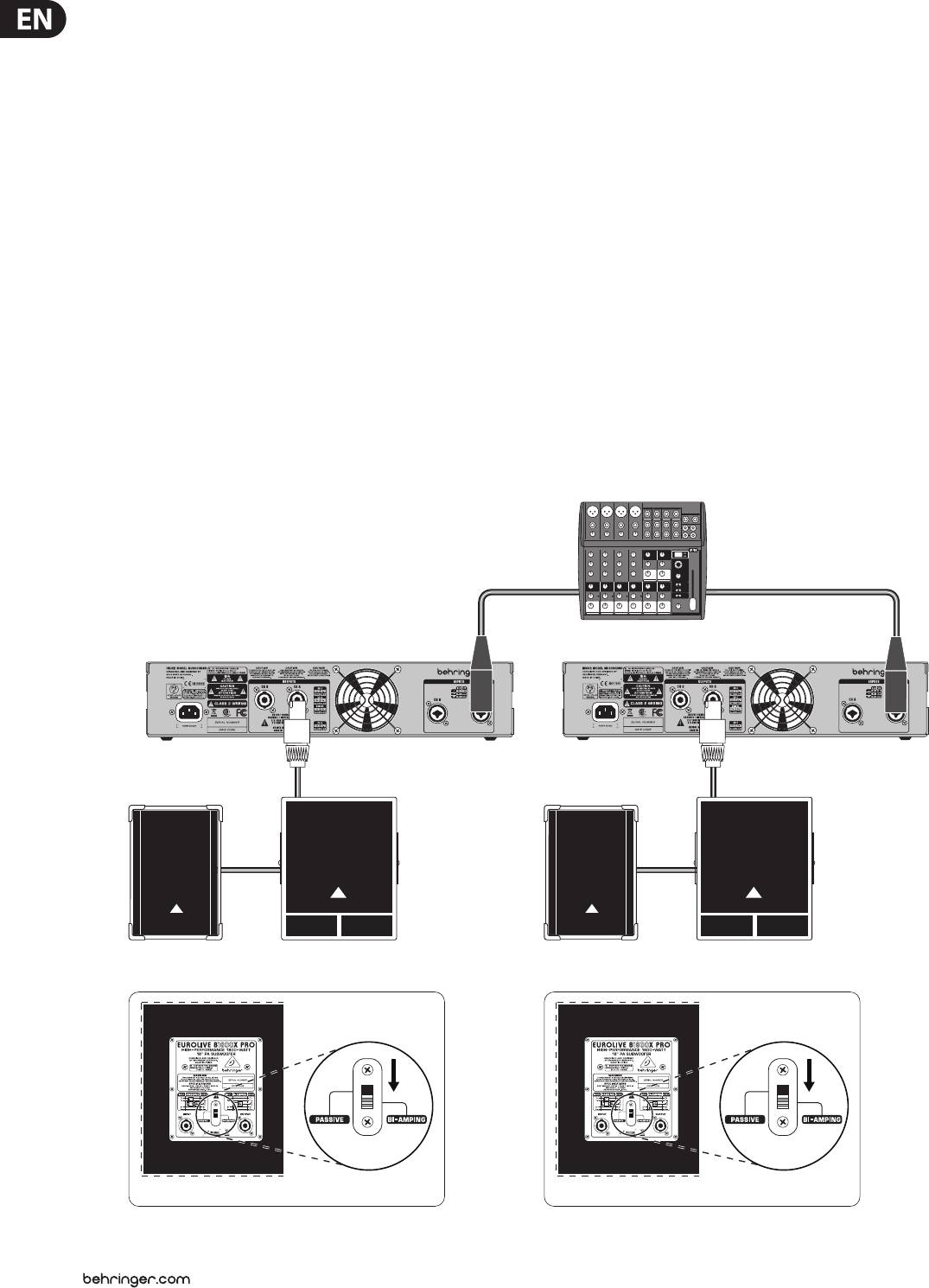
4.1 Bi-amping
For the current edition of the BEHRINGER Amp Remote software, only one iNUKE
Bi-amping splits a mono signal into upper and lower frequency bands, and then
amplier can appear at any one time in the amplier list and be recognized
assigns each frequency band to separate speaker cabinets. A subwoofer typically
by the software. Similarly, the IP address function can only be deployed with
takes the low frequency range. By splitting the signal this way, the speakers work
EUROCOM installed sound power ampliers.
more eciently, and you can achieve a cleaner overall sound.
Connecting to an amplier
Setting up hardware for bi-amping
◊ this procedure assumes you already have an iNUKE amplifier
1. Run a 4-pole speaker cable with professional twist-locking connectors from
connected to your computer, and that you are switching to another
OUTPUT CH A to the subwoofer. (The subwoofer receives its low-frequency
iNUKE amplifer. Usually, the Amp Remote software will automatically
signal from Channel B using poles 2+ and 2-, while the middle and upper
detect a USB-connected iNUKE amp and then ask if you wish to connect
frequency ranges use Channel A via poles 1+ and 1-.)
to the detected amplifer.
2. Set the subwoofer into BIAMPING mode.
1. Click on the Connect virtual button near the bottom of the Amp Connection
section of the Setup tab. The software will disconnect from the current
3. Run a 2-pole speaker cable with professional twist-locking connectors from
amplifer, clear the amplier from the list in the Amp Connection section,
the subwoofer to the other speaker.
and clear all presets from the Amp Presets list.
Programming DSP parameters for bi-amping
2. Press the Search virtual button near the top of the Amp Connection section,
above and to the left of the amplier list window. When the software nds
1. Choose the BIAMP1 setting on the Amp Mode screen.
your newly-connected iNUKE amp, the amplier will appear in the amplier
2. Go to the XOVER screen using the UP/DOWN buttons to set appropriate
list window, and the amp's internal presets will populate the Amp Presets
high/low crossover frequencies.
list. The software will also launch a conrmation window asking if you wish
to connect to the detected amplier.
3. In Channel A#1, choose your high-pass lter type (HPtype: BUT6, BUT12,
BES12, etc.) and set the cuto frequency (HPfreq) to approximately 100 Hz.
3. Press the Connect virtual button in the conrmation window to nalize
Deactivate the low-pass lter (LPtype: OFF) on this channel and set the gain
the connection.
level (Gain) to suit your system.
4. In Channel B#1, choose your low-pass lter type (LPtype: BUT6, BUT12,
BES12, etc.) and set the cuto frequency (LPfreq) to approximately 100 Hz.
Deactivate the high-pass lter (HPtype: OFF) on this channel and set the gain
level (Gain) to suit your system.
16 iNUKE NU6000DSP/NU3000DSP/NU1000DSP User Manual
Programming BEHRINGER Amp Remote Software for
Again, matching parameters will automatically appear in both lter’s Control
bi-amping
View settings.
1. Select the Conguration tab.
9. Set the crossover frequency by using any of these three methods:
2. Choose the Bi-Amp 2 signal path in the Conguration tab. A conrmation
a) Rotate the Low Pass 2 or High Pass 3 virtual Freq knobs in the Control View.
window will pop up.
The crossover frequency displayed in the Freq box below the virtual knob
will change simultaneously for both lters.
3. Click “Yes” on the Amp Mode conrmation window.
b) Select the text box below either Freq virtual knob, and type your desired
4. Select the Filter/Crossover tab.
frequency directly into the text box.
5. Select the X-Over button below the Frequency Curve display. A conrmation
c) Go to the Frequency Curve display, click on the frequency line marked “2,”
window will up up asking if you wish to set a Default Crossover.
and drag the frequency line to the desired area of the Frequency Curve.
6. Click “Yes” in the conrmation window. The X-Over button will illuminate,
Parameter settings and virtual knobs in the Control View will automatically
and default crossover settings will appear in the Frequency Curve and
move and change as you drag the crossover frequency through the
Control View.
Frequency Curve window.
7. Choose a lter type from either the Low Pass 2 or High Pass 3 Type pulldown
10. If necessary, adjust the Gain settings for Channel A and Channel B by rotating
menus (the software defaults to a Butterworth lter). Any changes to the
the respective Gain virtual knobs.
Low Pass 2 or High Pass 3 settings will also automatically appear in both
lter’s Control View settings.
8. Choose a lter slope setting from the Slope pulldown menu under either
Low Pass 2 or High Pass 3 (the software defaults to a Butterworth lter).
XLR balanced XLR balanced
XENYX 1202FX
NU3000DSP NU3000DSP
4-pole
4-pole
2-pole2-pole
B1800X PRO FrontEUROLIVE
B1800X PRO FrontEUROLIVE
B1520 PRO
B1520 PRO
B1800X PRO RearB1800X PRO Rear
17 iNUKE NU6000DSP/NU3000DSP/NU1000DSP User Manual
5. Installation
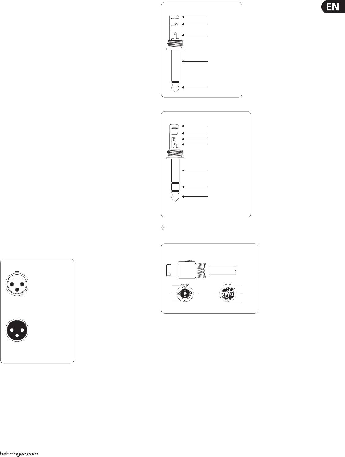
Unbalanced ¼" TS connector
strain relief clamp
5.1 Rack mounting
sleeve
Your iNUKE amplier ts into a 19" rack and requires two rack units. Install
tip
into the rack using four attaching screws and washers for the front panel.
Reinforce the back panel, especially if you will be taking the iNUKE on the
road. Make sure enough cool air reaches the rack, especially when other rack
equipment emanates a lot of heat. The iNUKE ampliers circulate heat from the
sleeve
(ground/shield)
rear to the front vents to relieve heat inside the rack enclosure.
Fan speed adjusts automatically to assure safe operation. Never block ventilation
openings. Should internal temperature reach extreme values, the unit will shut
tip
down automatically.
(signal)
5.2 Connections
5.2.1 Audio inputs
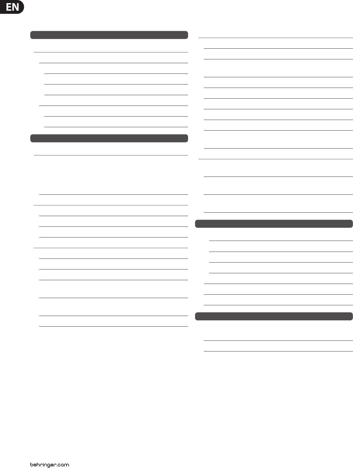
Balanced ¼" TRS connector
strain relief clamp
Each channel input uses combo jacks that can accept both balanced XLR and
¼" TRS stereo connectors, as well as unbalanced ¼" TS connectors. To deploy XLR
sleeve
ring
connectors for unbalanced signals, bridge pins 1 and 3; mono ¼" TS connectors
tip
do not require any alteration to carry unbalanced signals.
When working with balanced signals, please make sure to exclusively use
balanced cables. One unbalanced cable in the signal chain can change a balanced
sleeve
signal into an unbalanced signal.
ground/shield
ring
5.2.2 Outputs
cold (-ve)
tip
Your iNUKE amplier requires two twist-locking professional speaker connectors.
hot (+ve)
These professional speaker connectors were developed specially for driving
For connection of balanced and unbalanced plugs,
high-powered speakers. The connectors snap in securely, prevent electric shock,
ring and sleeve have to be bridged at the stereo plug.
and ensure correct polarity.
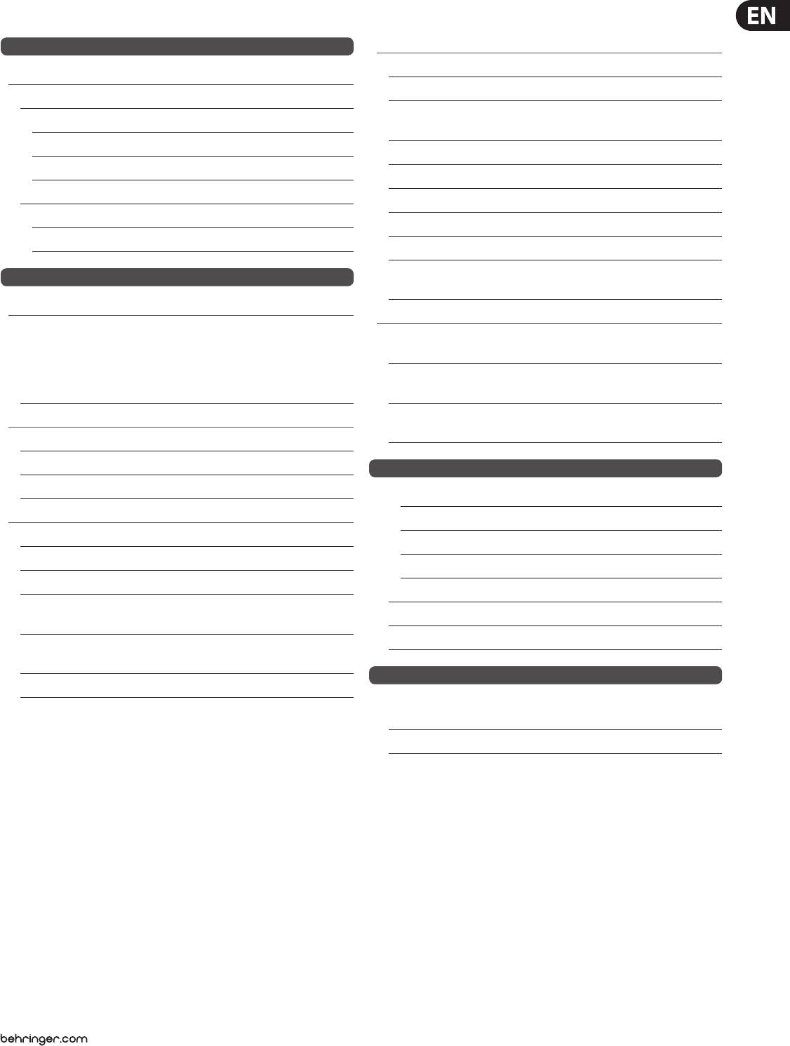
Inside the professional speaker connector, the 1+ pin (see gure) carries signal
◊ Whenever possible, use thick and short speaker cables to minimize
from either one or both channels, and this pin therefore suits mono-bridged
power loss. Never lay output cables near input cables.
operation (use pins 1+ and 2+). The lower connector, the 2+ pin, carries signal
from CH B only.
Professional speaker connector
(compatible with Neutrik Speakon connectors)
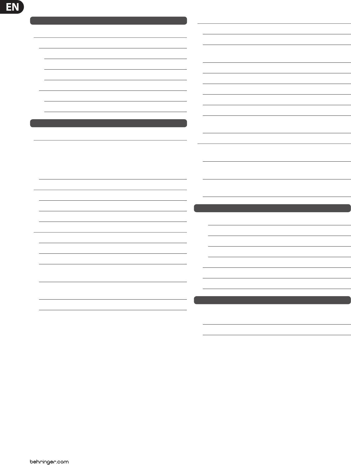
Balanced use with XLR connectors
12
3
1+
1+
2-
1-
1-
2-
input
2+
2+
1 = ground/shield
front view rear view
2 = hot (+ve)
3 = cold (-ve)
1
2
5.2.3 Connecting to the mains
3
Always connect your iNUKE amplier to the voltage specied on the rear of the
output
device. Connecting the amp to an incorrect voltage can permanently damage
your amp.
For unbalanced use, pin 1 and pin 3
have to be bridged
Before powering up the amplier, double-check all connections and fully lower
the gain setting.
18 iNUKE NU6000DSP/NU3000DSP/NU1000DSP User Manual
6. Specications
NU6000DSP
Output Power
Connectors
Inputs 2 x combo jacks
Maximum Output Power
Input impedance 10 kΩ unbalanced, 20 kΩ balanced
Stereo
Outputs 2 x locking-style professional
8 Ω per channel, stereo 1600 W
speaker connectors
4 Ω per channel, stereo 3100 W
Output circuit type Class D
2 Ω per channel, stereo —
Distortion <0.2%
Bridged mono
Frequency response 20 Hz to 20 kHz, +0 / -2 dB
8 Ω —
Damping factor >140 @ 8 Ω
4 Ω —
Signal-to-noise >98 dB
System
USB Front panel USB connector type B for
remote control of DSP section
Controls
Circuit Protection
Front Power switch, Gain controls
Cooling Continuously variable speed fan,
(channels A and B)
Back-to-front air ow
DSP section rotary push-encoder,
Buttons for Process, Setup,
Amplier protection Thermal and DC protection, Stable into
Up/Down, Exit
reactive or mismatched loads
Indicators
Load protection On/o muting, DC-fault power
supply shutdown
Power Amber backlit illuminated gain controls
Limit (per channel) 0 dB, full scale
Power Supply, Power Consumption @ 1/8 Rated Power, Voltage (Breaker/Fuses)
Signal (per channel) -24, -12, -6 dB
USA / Canada 120V~, 60Hz (25A)
Digital Signal Processing (DSP)
UK / Australia / Europe 220-240 V~, 50/60 Hz, (12A)
Display LCD 128 x 32, amber backlit
Korea / China 220-240 V~, 50/60 Hz,(12A)
Digital delay function (per channel) 0 - 300 ms
Japan 100 V~, 50/60 Hz, (25A)
Digital crossover function 3 lter types, up to 48 dB/octave
Power consumption @ 2 ohms —
Digital EQ function (per channel) 8-band parametric,
Power consumption @ 4 ohms 620 W
2-band dynamic equalizer
Mains connector Standard IEC receptacle
Digital dynamics function Zero attack limiter (peak)
(per channel)
Dimensions/Weight
Presets 20 total presets, 19 user-denable
Dimensions (H x W x D) appr. 3.5 x 19 x 12.91"
appr. 89 x 483 x 328 mm
Weight appr. 11.9 lbs / 5.4 kg
19 iNUKE NU6000DSP/NU3000DSP/NU1000DSP User Manual
NU3000DSP
Output Power
Connectors
Inputs 2 x combo jacks
Maximum Output Power
Input impedance 10 kΩ unbalanced, 20 kΩ balanced
Stereo
Outputs 2 x locking-style professional
8 Ω per channel, stereo 440 W
speaker connectors
4 Ω per channel, stereo 820 W
Output circuit type Class D
2 Ω per channel, stereo 1520 W
Distortion <0.3%
Bridged mono
Frequency response 20 Hz to 20 kHz, +0 / -1 dB
8 Ω 1520 W
Damping factor >145 @ 8 Ω
4 Ω 3000 W
Signal-to-noise >98 dB
System
USB Front panel USB connector type B for
remote control of DSP section
Controls
Circuit Protection
Front Power switch, Gain controls
Cooling Continuously variable speed fan,
(channels A and B)
Back-to-front air ow
DSP section rotary push-encoder,
Buttons for Process, Setup,
Amplier protection Thermal and DC protection, Stable into
Up/Down, Exit
reactive or mismatched loads
Indicators
Load protection On/o muting, DC-fault power
supply shutdown
Power Amber backlit illuminated gain controls
Limit (per channel) 0 dB, full scale
Power Supply, Power Consumption @ 1/8 Rated Power, Voltage (Breaker/Fuses)
Signal (per channel) -24, -12, -6 dB
USA / Canada 120 V~, 60 Hz (T 10 A H 250 V)
Digital Signal Processing (DSP)
UK / Australia / Europe 220-240 V~, 50/60 Hz (T 6.3 A H 250 V)
Display LCD 128 x 32, amber backlit
Korea / China 220-240 V~, 50/60 Hz (T 6.3 A H 250 V)
Digital delay function (per channel) 0 - 300 ms
Japan 100 V~, 50/60 Hz (T 10 A H 250 V)
Digital crossover function 3 lter types, up to 48 dB/octave
Power consumption @ 2 ohms 350 W
Digital EQ function (per channel) 8-band parametric,
Power consumption @ 4 ohms 210 W
2-band dynamic equalizer
Mains connector Standard IEC receptacle
Digital dynamics function Zero attack limiter (peak)
(per channel)
Dimensions/Weight
Presets 20 total presets, 19 user-denable
Dimensions (H x W x D) appr. 3.5 x 19 x 9.76"
appr. 89 x 483 x 248 mm
Weight appr. 6.8 lbs / 3.1 kg
20 iNUKE NU6000DSP/NU3000DSP/NU1000DSP User Manual
NU1000DSP
Output Power
Connectors
Inputs 2 x combo jacks
Maximum Output Power
Input impedance 10 kΩ unbalanced, 20 kΩ balanced
Stereo
Outputs 2 x locking-style professional
8 Ω per channel, stereo 160 W
speaker connectors
4 Ω per channel, stereo 310 W
Output circuit type Class D
2 Ω per channel, stereo 530 W
Distortion <0.1%
Bridged mono
Frequency response 20 Hz to 20 kHz, +0 / -1 dB
8 Ω 620 W
Damping factor >155 @ 8 Ω
4 Ω 1050 W
Signal-to-noise >98 dB
System
USB Front panel USB connector type B for
remote control of DSP section
Controls
Circuit Protection
Front Power switch, Gain controls
Cooling Continuously variable speed fan,
(channels A and B)
Back-to-front air ow
DSP section rotary push-encoder,
Buttons for Process, Setup,
Amplier protection Thermal and DC protection, Stable into
Up/Down, Exit
reactive or mismatched loads
Indicators
Load protection On/o muting, DC-fault power
supply shutdown
Power Amber backlit illuminated gain controls
Limit (per channel) 0 dB, full scale
Power Supply, Power Consumption @ 1/8 Rated Power, Voltage (Breaker/Fuses)
Signal (per channel) -24, -12, -6 dB
USA / Canada 120 V~, 60 Hz (T 6.3 A H 250 V)
Digital Signal Processing (DSP)
UK / Australia / Europe 220-240 V~, 50/60 Hz (T 3.15 A H 250 V)
Display LCD 128 x 32, amber backlit
Korea / China 220-240 V~, 50/60 Hz (T 3.15 A H 250 V)
Digital delay function (per channel) 0 - 300 ms
Japan 100 V~, 50/60 Hz (T 6.3 A H 250 V)
Digital crossover function 3 lter types, up to 48 dB/octave
Power consumption @ 2 ohms 150 W
Digital EQ function (per channel) 8-band parametric,
Power consumption @ 4 ohms 70 W
2-band dynamic equalizer
Mains connector Standard IEC receptacle
Digital dynamics function Zero attack limiter (peak)
(per channel)
Dimensions/Weight
Presets 20 total presets, 19 user-denable
Dimensions (H x W x D) appr. 3.5 x 19 x 9.76"
appr. 89 x 483 x 248 mm
Weight appr. 6.4 lbs / 2.9 kg

21 iNUKE NU6000DSP/NU3000DSP/NU1000DSP User Manual
FEDERAL COMMUNICATIONS
COMMISSION COMPLIANCE
INFORMATION
iNUKE NU6000DSP/NU3000DSP/
NU1000DSP
Responsible Party Name: MUSIC Group Services US Inc.
Address: 18912 North Creek Parkway,
Suite 200 Bothell, WA 98011,
USA
Phone/Fax No.: Phone: +1 425 672 0816
Fax: +1 425 673 7647
iNUKE NU6000DSP/NU3000DSP/NU1000DSP
complies with the FCC rules as mentioned in the followingparagraph:
This equipment has been tested and found to comply with the limits for a ClassB
digital device, pursuant to part 15 of the FCC Rules. These limits are designed
to provide reasonable protection against harmful interference in a residential
installation. This equipment generates, uses and can radiate radio frequency
energy and, if not installed and used in accordance with the instructions, may cause
harmful interference to radio communications. However, there is no guarantee that
interference will not occur in a particular installation. If this equipment does cause
harmful interference to radio or television reception, which can be determined
by turning the equipment o and on, the user is encouraged to try to correct the
interference by one or more of the followingmeasures:
• Reorient or relocate the receiving antenna.
• Increase the separation between the equipment and receiver.
• Connect the equipment into an outlet on a circuit dierent from that to which the
receiver is connected.
• Consult the dealer or an experienced radio/TV technician forhelp.
This device complies with Part 15 of the FCC rules. Operation is subject to the
following two conditions:
(1) this device may not cause harmful interference, and
(2) this device must accept any interference received, including interference that may
cause undesired operation.
Important information:
Changes or modications to the equipment not expressly approved by MUSIC Group
can void the user’s authority to use the equipment.
We Hear You


