Leadtek WinFast VP200P: инструкция
Раздел: Программное Обеспечение
Тип:
Инструкция к Leadtek WinFast VP200P

®
WinFast
®
VP200 PCoIP Virtual Desktop System
Quick Start Guide

Copyright 2010 Leadtek Research Inc. All rights reserved.
No part of this document may be copied or reproduced in any form or by any means without the prior written
consent of Leadtek Research Inc.
Leadtek makes no warranties with respect to this documentation and disclaims any implied warranties of
merchantability, quality, or fitness for any particular purpose. The information in this document is subject to
change without notice. Leatek reserves the right to make revisions to this publication without obligation to
notify any person or entity of any such changes.
PC-over-IP and PCoIP are registered trademarks of Teradici Corporation. Trademarks or brand names
mentioned herein are trademarks or registered trademarks of their respective owners.
International Headquarters
18F, No. 166, Chien Yi Rd., Chung Ho,
Taipei County, Taiwan, (23511)
Tel:+886 2 8226 5800 Fax: +886 2 8226 5801
http://www.leadtek.com E-Mail: contact@leadtek.com
WinFast VP200 Quick Start Guide
Version B Code: LR2916, LR2917
January 2010 P/N: W05G0392

Table of Contents
English ...................................................... 1
Français .................................................... 7
Deutsch ................................................... 13
Русский ................................................... 19
日本語 ..................................................... 25
한국어 .................................................. 31
簡體中文 .................................................
37
繁體中文 .................................................
43
®
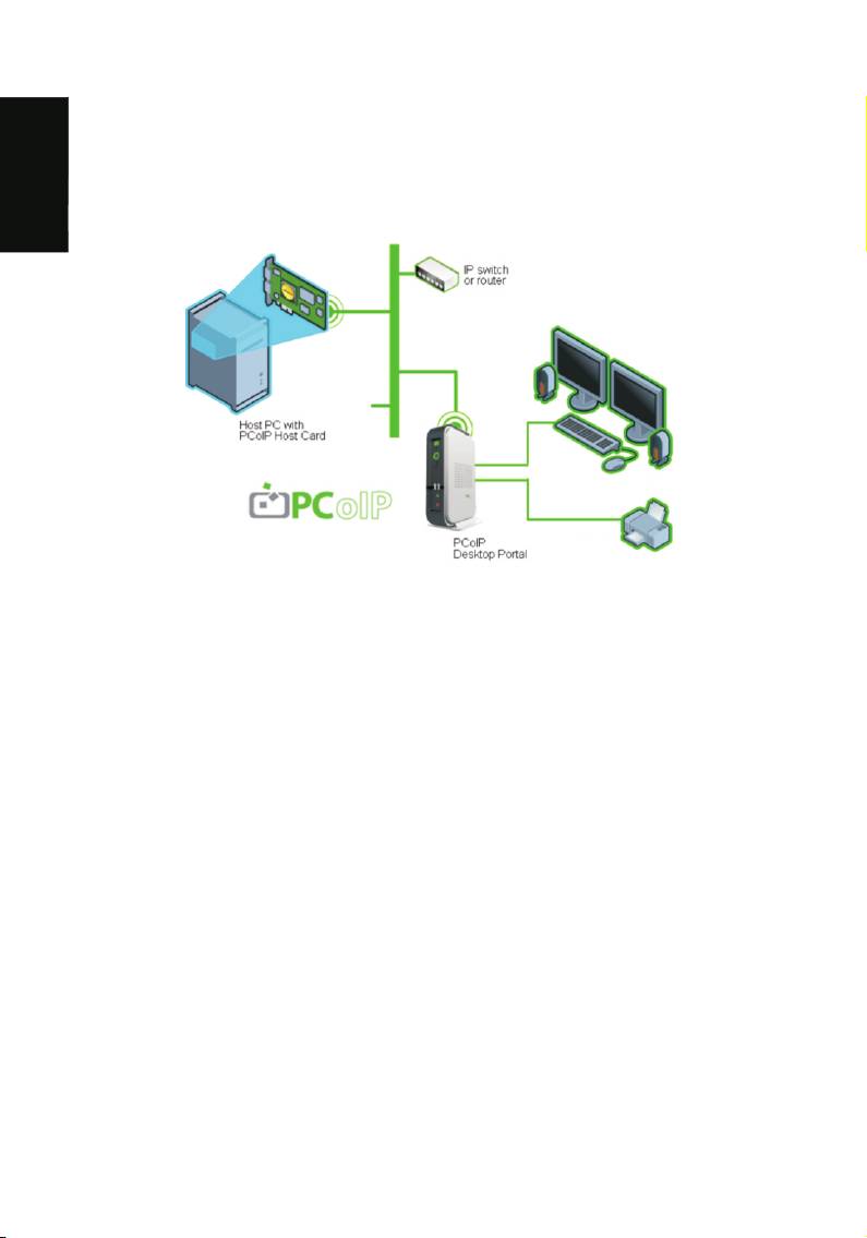
Thank you for purchasing the VP200 PCoIP Virtual Desktop System.
This guide will help you establish a remote connection to a host PC using the
®
advanced PC-over-IP (PCoIP) technology, enabling you to use applications
and desktop peripherals as if you were using them locally.
English
PCoIP Technology is designed to deliver a user's desktop from a centralized
host PC with an immaculate, uncompromised end user experience across
standard IP networks – including full DVI dual monitor video, complete USB
1.1 compatibility, and full-duplex high-definition audio.
Package Contents
VP200 P Desktop Portal Package Includes:
VP200 P PCoIP Desktop Portal and power supply
Ethernet cable
Quick Start Guide (this document) and Documentation CD
VP200 H PCIe Host Card Package includes:
VP200 H PCoIP Host Card
Ethernet cable
DMS-59 to dual DVI cable
Low Profile bracket (Optional)
PCoIP Host Card Power Button Cable (Optional: see Remote Power
Management)
Quick Start Guide (this document) and Documentation CD
1
Not included:
PC with single or dual DVI graphics card, and 1 available PCIe slot
Ethernet LAN switch or router (10/100/1000 Mbps)
USB keyboard and mouse
English
Monitor with DVI or VGA (adapter required)
Optional: PC speakers and other USB peripherals
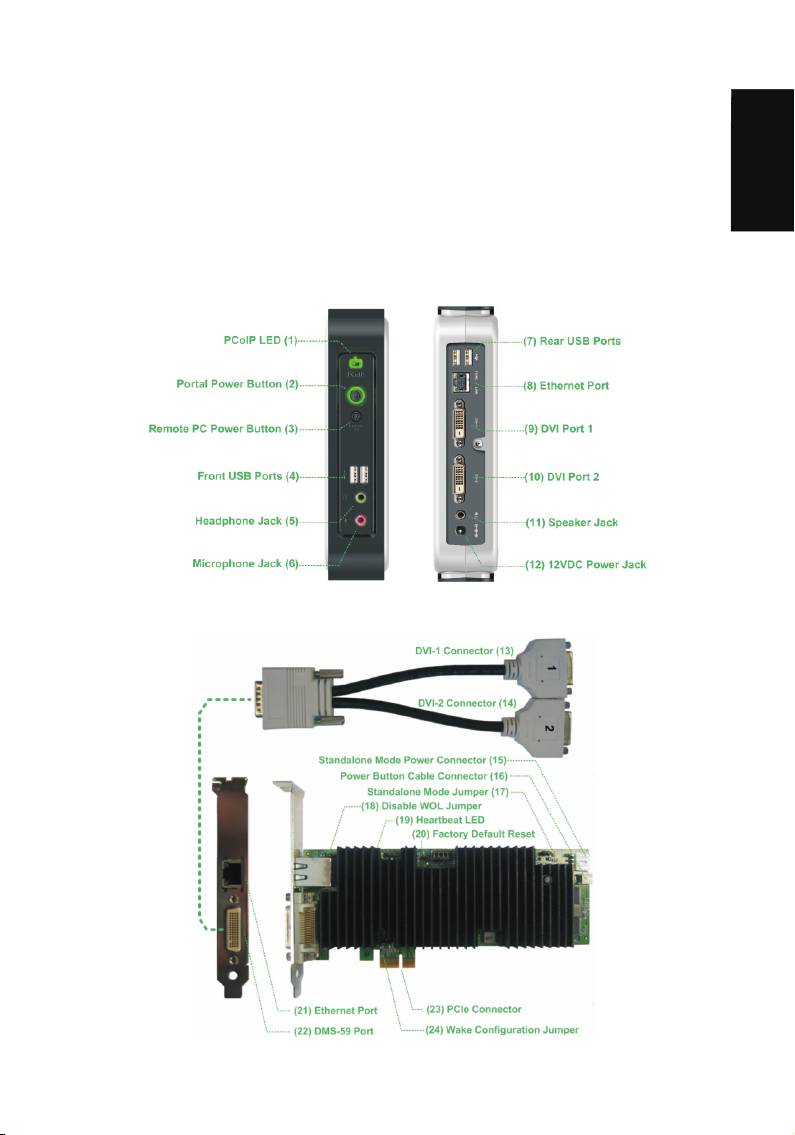
VP200 P PCoIP Desktop Portal
VP200 H PCoIP PCIe Host Card
2

WARNING
1. Always power down and disconnect devices from AC power before handling them.
Failure to do this can result in personal injury or equipment damage. Some circuitry
on the host PC can continue to operate even though the front panel power switch is
English
off.
2. The Standalone Mode Power Connector on the host card must be disconnected
when the host card is operating in PCIe powered mode. Failure to do this can result
in damage to the host card.
Setup Instructions
PCoIP Virtual Desktop System (Portal + Host Card), follow steps 1 through 3.
PCoIP Desktop Portal only, follow step 1.
PCoIP PCIe Host Card only, follow step 2.
1 PCoIP Desktop Portal Installation
1. Be sure the monitor and the Portal are turned off and disconnected from AC power.
2. Use a DVI cable to connect the monitor to the Portal's DVI Port 1 (9).
3. Plug the monitor's power cable into an AC outlet and power it on.
4. If you are using dual monitors, repeat Steps 1 through 3 but connect the second
monitor to the Portal's DVI Port 2 (10).
5. Connect a USB keyboard and mouse to the Portal's rear USB ports (7).
6. Use an Ethernet cable to connect the Ethernet switch or router to the Portal's
Ethernet jack (8).
7. Connect the Portal power supply to the Portal's power jack (12), then plug the Portal
power supply into a surge-protected AC outlet.
8. Optionally connect the following devices to the Portal:
PC speaker to Speaker jack (11)
Headphones and MIC to Headphone (5) and Microphone jacks (6)
USB peripherals to auxiliary USB ports (4)
9. Power on the Portal by pushing the power button (2). The power button will light
steady green and the monitor will display the On Screen Display (OSD).
NOTE
If the monitor does not show the On Screen Display (OSD), check all connectors and be
sure the monitor and Power are powered on. Note the LED indicators:
Off: AC power is off
Solid yellow: AC power is on and Portal power is off
Solid green: Portal power is on
Blinking green: Host PC is in low-power states
3

2 PCoIP PCIe Host Card Installation
1. Check the jumpers on the Host card to ensure they are in the correct setting. See
Host Card Jumper Settings for details.
2. Be sure the Host PC is turned off and unplugged from AC power.
3. Open the PC's case.
English
4. Install the Host Card into a free PCIe slot and secure the metal bracket.
5. Connect the DMS-59 to dual DVI cable to the Host Card's DMS-59 connector (22)
and connect the DVI-1 connector (13) to the PC's graphics card. If you are using
dual monitors, connect the graphics card's second DVI-out port to the DVI-2
connector (14).
6. Use an Ethernet cable to connect the Ethernet switch or router to the Host Card's
Ethernet jack (21), then power on the Ethernet switch or router.
7. Close the Host PC's case and plug the Host PC into a surge-protected AC outlet.
3 Establishing a PCoIP Connection
1. Power on the host PC.
2. Wait until the “Connect” button on the Portal On Screen Display (OSD) user screen
is active.
Connect button is inactive Connect button is active
3. Use the mouse connected to the Portal to click “Connect” on the OSD screen. The
message “Discovering hosts, please wait …” will appear on the monitor.
4. A list of available Hosts on the network will appear on the OSD.
5. Select the Host Card you wish to connect and click “OK”.
6. The Portal's PCoIP LED (1) will light green, indicating a successful PCoIP
connection.
7. If you are using dual monitors, remember to configure the graphics card for dual-
monitor operation.
8. When the Host PC finishes booting, use the Portal as you would a normal desktop
PC.
NOTE
If the “Connect” button on the Portal OSD is inactive or if the Portal can not discover any
Host Cards on the IP network, check the network connection and be sure the Ethernet
switch or router is powered on.
Additional Notes
Monitor types:
In addition to DVI monitors, the Portal is compatible with analog VGA and digital HDMI
monitors. Simply attach a DVI-to-VGA or DVI-to-HDMI adapter to the Portal's DVI
connector.
4

Audio:
The Portal uses the Realtek High-Definition Audio Codec. Windows Vista natively
contains an HD Audio driver for this Codec. For other operating systems, including
Windows XP, please install the High-Definition Audio Codec driver from
English
www.realtek.com to use PCoIP System's full audio capabilities.
IP Address:
The Portal and Host are set to DHCP client mode by default. Normally, the IP address
of the Portal and Host are assigned by the DHCP server on your IP network. If your IP
network does not have a DHCP server, the Portal and Host Card will fall back to a static
IP address mode after a timeout period of approximately 2 minutes. In the fall back
static IP address mode, you can access the Portal and Host web interface to disable
DHCP client mode and assign a static IP address. The Portal's fall back IP address is
192.168.1.50 and Host's fall back IP address is 192.168.1.100.
Portal Buttons:
The Portal's Power Button (2) is a multi-function button.
! A short push (< 4 seconds) power on the Portal.
! A long push (> 4 seconds) power off the Portal.
! When the Portal is connected in a session, a short push will disconnect it from the
Host.
The Portal's Remote PC Power Button (3) is used to remotely control the host PC's
front-panel power switch. To enable this function, the PCoIP Host Card Power Button
Cable must be connected as described in Remote Power Management.
! A short push (< 4 seconds) set the host PC to sleep.
! A long push (> 4 seconds) shut down the host PC.
Host Card Factory Default Reset:
To reset the Host Card to its factory default configuration:
1. Power off the Host PC and disconnect it from AC power.
2. Insert a jumper to the Factory Default Reset header JP1 (20).
3. Power on the Host Card and wait until the heartbeat LED (19) blinks.
4. Power off the Host PC.
5. Remove the Factory Default Reset jumper JP1.
5
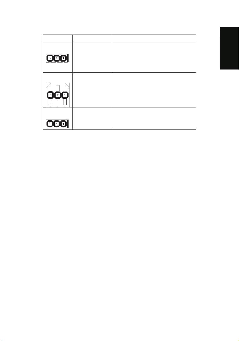
Host Card Jumper Settings:
Jumper Label Settings
JP6 (17)
STANDALONE 1-2: Standalone powered mode. In
this mode, the Host Card is
powered from the standalone
English
mode power connector J4.
2-3: PCIe powered mode (default)
JP12 (24)
WAKE CONFIG 1-2: Wake via PCIe slot
2-3: Wake via power button (default)
JP13 (18)
DISABLE WOL 1-2: Disable wake-on-LAN
2-3: Enable wake-on-LAN (default)
Remote Power Management
During PCoIP sessions, you can use the Portal's Remote PC Power Button (3) to
change the Host PC's power state. To enable this function, the PCoIP Host Card Power
Button Cable must be connected as described below. This section assumes you have
advanced PC hardware experience.
1. Be sure the Host PC is turned off and unplugged from AC power.
2. Open the PC's case.
3. Connect the Power Button Cable to the Host Card cable connector (16).
4. Disconnect the PC's front-panel power button cable from the motherboard. (If the PC
uses a single connector for all front-panel buttons and jacks, disconnecting it will
disable all these devices.)
5. Connect the other end of the Power Button Cable to the motherboard's power switch
header. Be sure to connect the red wire to the power-on pin and the black wire to the
ground pin on the PC's motherboard.
6. If possible, connect the PC's front-panel power button cable to the 2-pin header on
the Power Button Cable. If this is not possible, the PC's front-panel power button will
be disabled.
7. Close the Host PC's case and plug the Host PC into a surge-protected AC outlet.
8. Power up the Host PC using the Portal's Remote PC power button (3). This button
can also be used to wake the Host PC from Sleep states.
Need More Help?
Please refer to the documents on the Documentation CD for more information.
6
Оглавление
- English ...................................................... 1 Français .................................................... 7 Deutsch ................................................... 13 Русский ................................................... 19 日本語 ..................................................... 25 한국어 .................................................. 31 簡體中文 .................................................
- English
- Français
- Deutsch
- 繁體中文
