E-Tech VS series 4" submersible pumps: инструкция
Раздел: Инструмент, электроинструмент, силовая техника
Тип: Насос
Инструкция к Насосу E-Tech VS series 4" submersible pumps
POMPE SOMMERSE 4"- 6" E 8"
4"- 6" AND 8" SUBMERSIBLE PUMPS
TAUCHPUMPEN 4"- 6" UND 8"
POMPES SUBMERSIBLES 4"- 6" ET 8"
BOMBAS SUMERGIBLES 4"- 6" Y 8"
POMPY GŁĘBINOWE 4"- 6" I 8"
4"- 6" OG 8" UNDERVANDSPUMPER
UPPOPUMPUT, 4"- 6" JA 8"
ΥΠΟΒΡΥΧΙΕΣ ΑΝΤΛΙΕΣ 4"- 6" ΚΑΙ 8"
DOMPELPOMPEN, 4"- 6" EN 8"
4"- 6" OG 8" NEDSENKBARE PUMPER
BOMBAS SUBMERSÍVEIS DE 4"- 6" E 8"
4 - 6 OCH 8 TUMS DRÄNKBARA PUMPAR
4"- 6" И 8" ПОГРУЖНЫЕ НАСОСЫ
Manuale d’uso e installazione
Use and installation instructions
Gebrauchs- und Aufstellungshandbuch
Manuel pour l’emploi et installation
Manual de empleo e instalación
Instrukcja obsługi i instalacji
Brugs- og installationsanvisninger
Käyttö- ja asennus-ohjeet
Οδηγίες χρήσης και εγκατάστασης
Gebruiks- en installatie-instructies
Instruks for bruk og installasjon
Instruções de utilização e instalação
Instruktioner för användning och installation
Руководство по монтажу и эксплуатации

POMPE SOMMERSE 4"- 6" e 8"
Manuale d’uso e installazione .................... pag. 3
4"- 6" AND 8" SUBMERSIBLE PUMPS
Installation and operation manual ................ pag. 8
TAUCHPUMPEN 4"- 6" und 8"
Bedienungs- und Installationshandbuch ............ pag. 13
POMPES SUBMERSIBLES 4"- 6" et 8"
Manuel d’instructions pour l’emploi et l’installation .. pag. 18
BOMBAS SUMERGIBLES 4"- 6" y 8"
Manual de uso e instalación ..................... pag. 23
POMPY GŁĘBINOWE 4"- 6" I 8"
Instrukcja obsługi i instalacji .................... pag. 28
4"- 6" OG 8" UNDERVANDSPUMPER
Installations og betjeningsvejledning .............. pag. 33
UPPOPUMPUT, 4"- 6" JA 8"
Asennuksen ja käytön käsikirja .................. pag. 38
ΥΠΟΒΡΥΧΙΕΣ ΑΝΤΛΙΕΣ 4"- 6" ΚΑΙ 8"
Εγχειρίδιο εγκατάστασης και λειτουργίας ........... pag. 43
DOMPELPOMPEN, 4"- 6” en 8”
Installatie- en gebruikshandleiding................ pag. 48
4"- 6" OG 8" NEDSENKBARE PUMPER
Håndbok for installasjon og bruk ................. pag. 53
BOMBAS SUBMERSÍVEIS de 4"- 6" E 8"
Manual de instalação e de operação . ............. pag. 58
4 - 6 OCH 8 TUMS DRÄNKBARA PUMPAR
Manual för installation och funktion ............... pag. 63
4"- 6" И 8" ПОГРУЖНЫЕ НАСОСЫ
Руководство по монтажу и эксплуатации ......... pag. 68
2

• compromissione delle operazioni di manutenzione,
ï IT ð
• danni corporali di ordine elettrico, meccanico o chimico.
Queste istruzioni per l’esercizio racchiudono importanti
Norme di sicurezza
indicazioni e avvertimenti. Preghiamo di leggerle prima
Tutte le istruzioni di sicurezza presenti in questo manuale
del montaggio, del collegamento elettrico e della messa
devono essere rispettate, così come le prescrizioni di
in marcia.
legge nazionali in materia di prevenzione degli incidenti
e le regole interne di utilizzo delle installazioni e di
Generalità
sicurezza sul lavoro.
La pompa è stata realizzata secondo le tecniche più
avanzate e recenti, nel pieno rispetto delle norme in vigore
Istruzioni di sicurezza per i lavori di controllo,
ed è sottoposta a un controllo di qualità permanente.
manutenzione e servizio
Il presente manuale vi sarà di aiuto nella comprensione
Il responsabile deve vericare che tutti i lavori di
del funzionamento della pompa e vi aiuterà a conoscere
manutenzione, di ispezione e di montaggio vengano
le sue possibili applicazioni.
eseguiti da personale qualicato e autorizzato. Prima di
Il manuale d’uso contiene raccomandazioni importanti
procedere a tali lavori è necessario che tale personale
necessarie al corretto ed economico funzionamento della
venga a conoscenza del contenuto del presente manuale.
pompa. È necessario rispettare tali raccomandazioni al
Come regola generale, tutti i lavori sulle macchine
ne di garantire l’afdabilità, la durata e di evitare i rischi
devono essere eseguiti solo ad arresto totale delle dette
di incidente derivanti da un uso improprio.
macchine. È assolutamente necessario rispettare la
La pompa non deve essere utilizzata al di fuori dei
procedura di arresto descritta in questo manuale.
limiti descritti nelle speciche tecniche. È necessario
Le pompe che veicolano uidi pericolosi per la salute
rispettare le indicazioni riguardanti la natura, la densità, la
devono essere decontaminate.
temperatura, la portata del liquido pompato, la velocità di
Alla ne dei lavori, tutti i dispositivi di sicurezza e di
rotazione, la pressione, la potenza del motore così come
protezione devono essere rimontati e rimessi in funzione.
tutte le altre istruzioni contenute nel presente manuale o
la documentazione allegata al contratto.
Modica e fabbricazione di pezzi di ricambio da parte
La targhetta indica la gamma, le speciche principali
del cliente
di servizio e il numero di serie. È importante fornire tali
La ricostruzione o modica della macchina deve essere
indicazioni al momento della richiesta di intervento o di
sempre approvata dal costruttore prima di essere
assistenza e per ordinare i pezzi di ricambio.
effettuata. I pezzi di ricambio originali e gli accessori forniti
dal costruttore garantiscono la sicurezza. Il costruttore
Norme di sicurezza
non sarà in nessun caso responsabile delle conseguenze
Il presente manuale contiene istruzioni fondamentali da
derivanti dall’uso di pezzi di ricambio non originali!
rispettare al momento dell’installazione, dell’uso e della
manutenzione. Il presente manuale deve assolutamente
1. CONSEGNA E MAGAZZINAGGIO
essere consultato dall’addetto al montaggio e da tutto
il personale qualicato che ne seguirà il funzionamento
1.1 Consegna
designato dal responsabile installazioni. Inoltre, tale
Le pompe sommerse vengono fornite nel loro imballo
manuale deve essere sempre a disposizione sul luogo di
originale nel quale devono rimanere no al momento
utilizzo della macchina.
dell’installazione.
Abbiate cura di non sottoporre la pompa a essione
Identicazione delle istruzioni codicate del presente
quando essa non è più imballata: ciò potrebbe causare
manuale
il disassamento e il danneggiamento della pompa stessa.
Le norme di sicurezza presenti in questo manuale,
La targa non applicata che viene fornita con la pompa,
la cui inosservanza può causare danni sici, sono
deve essere ssata vicino all’apparecchiatura elettrica di
contrassegnate dal simbolo generale di pericolo.
comando.
(simbolo di sicurezza)
La pompa non deve essere esposta a inutili urti e
collisioni.
m
1.2 Magazzinaggio e movimentazione
Rischi derivanti dal mancato rispetto delle norme di
sicurezza
Temperatura di magazzinaggio:
Il mancato rispetto delle norme di sicurezza può provocare
Pompa: dai -20°C a +60°C
danni sici e materiali oltre al possibile inquinamento
La pompa non deve essere esposta ai raggi solari.
dell’ambiente. L’inosservanza delle norme di sicurezza
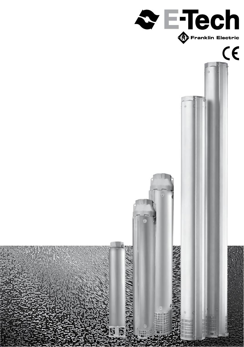
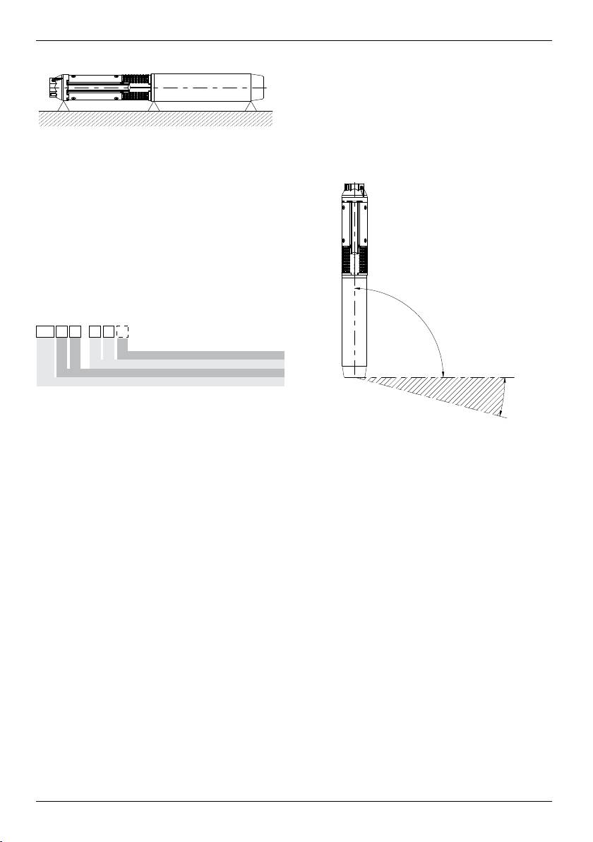
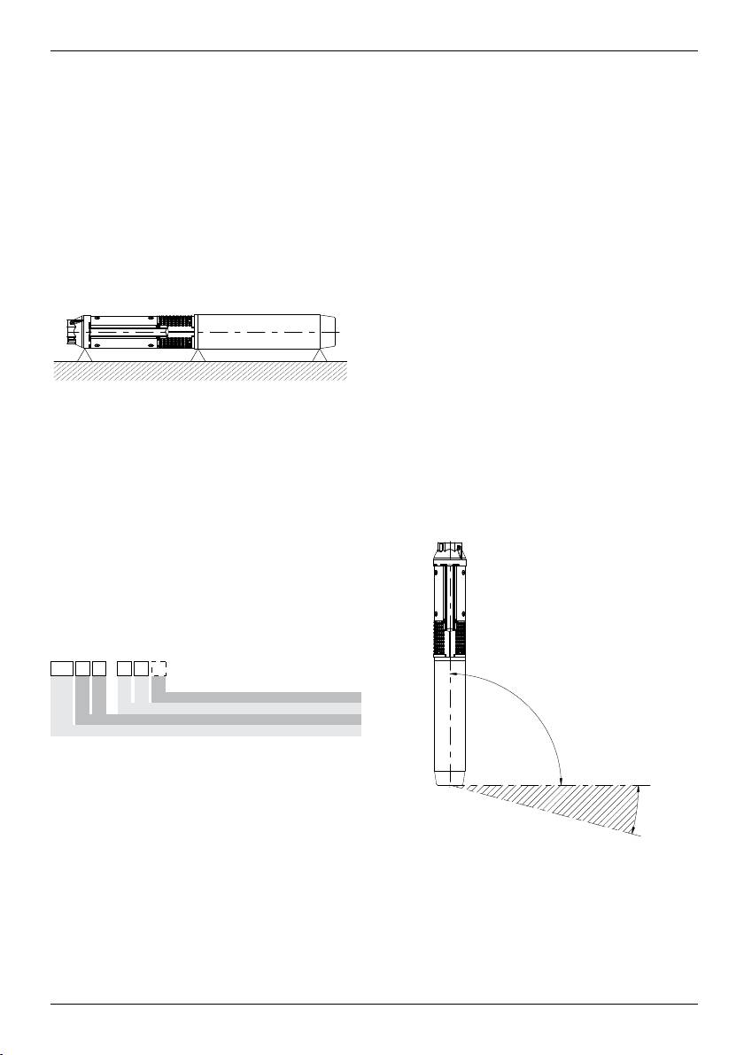
Se la pompa non è stata imballata, dovrà essere
può portare alla perdita totale dei diritti di garanzia.
conservata in magazzino orizzontalmente,
Per citare qualche esempio, il mancato rispetto di dette
adeguatamente sostenuta, oppure verticalmente,
norme può provocare:
per prevenire il possibile disassamento. Durante lo
• il guasto delle funzioni principali della macchina o
stoccaggio, la pompa può essere sostenuta come
dell’installazione,
mostrato in Fig. 1.
3
4
00114017 09/2008
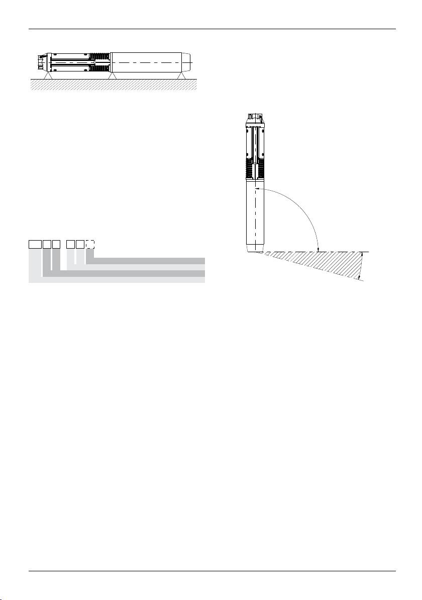
La pompa è adatta per installazione sia verticale che
orizzontale, mai con inclinazione verso il basso, Fig. 2.
Nota: Durante il funzionamento il supporto di aspirazione
deve sempre essere sommerso.
In speciali condizioni può essere necessario sommergerlo
00114017 06/2010
più a fondo in funzione del punto di lavoro, temperature e
Fig. 1
NPSH della pompa.
Se la pompa non viene impiegata in posizione verticale,
bisogna provvedere a sostenere sia la parte pompa che
il motore. Notare che il baricentro varierà in base al tipo
di pompa.
2. DATI GENERALI
2.1 Descrizione generale
Le pompe sommerse sono pompe multistadio funzionanti
con senso di rotazione antiorario (osservando dal lato di
mandata) direttamente accoppiate a speciali motori (a
norme NEMA) sommergibili.
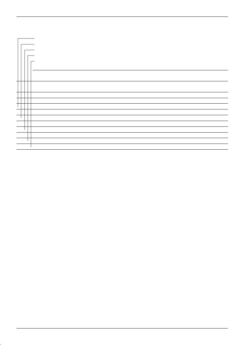
Codice di identicazione pompa
2.2 Applicazioni
Queste pompe sommerse, sono progettate per un’ampia
gamma di applicazioni, come l’approvvigionamento
idrico per abitazioni private, per acquedotti e industrie.
Indispensabili in caso di abbassamento del livello di falda
e per l’aumento pressione.
Immergete completamente la pompa sotto il livello
dell’acqua quando la installate sia orizzontalmente
che verticalmente. Vedere paragrafo 3.1 Limiti di
posizionamento.
2.3 Liquidi pompati
Liquidi puliti, compatibili con i materiali costruttivi della
pompa, senza particelle solide o bre.
Il contenuto massimo di sabbia nell’acqua non deve
superare i 50 g/m³. Una più alta concentrazione di sabbia
ridurrà la vita della pompa e aumenterà il rischio di blocco.
Se la pompa è utilizzata per pompare liquidi con una
densità superiore all’acqua, occorrerà usare un motore
con una potenza proporzionalmente maggiore.
3. INSTALLAZIONE / PREPARAZIONE
3.1 Limiti di posizionamento
Se la pompa viene installata in una posizione
accessibile alle persone, bisogna evitare ogni
m
possibilità di contatto tra giunto e persone, per
esempio dotandola di uno schermo protettivo.
00114018 09/2008
00114018 06/2010
Fig. 2
3.2 Diametro di pompa/motore
Vericare nel catalogo tecnico il massimo diametro della
pompa e della pompa con motore.
Vericate che il pozzo non presenti restrizioni o ostacoli
alla discesa della pompa.
3.3 Valvola di non-ritorno sulla tubazione di
mandata
La pompa incorpora una valvola di non-ritorno nella bocca
di mandata. È consigliabile tuttavia, particolarmente
nelle applicazioni in cui la pompa alimenta direttamente
una rete di distribuzione in pressione, installare un’altra
valvola di non-ritorno sulla tubazione di mandata a non
più di 10 metri dal livello minimo del pozzo (se non lo si
conosce usare la bocca di mandata come livello minimo).
La sua presenza attenua gli shock idraulici dovuti agli
avviamenti ed agli arresti.
4. COLLEGAMENTI ELETTRICI
Prima di iniziare a lavorare sulla pompa, bisogna
assicurarsi di aver disinserito il collegamento
m
elettrico e che non venga accidentalmente
reinserito.
4.1 Generalità
I collegamenti dovranno essere eseguiti da un elettricista
autorizzato secondo le regole vigenti.
... 7 N
8
/
1 5
... 7 N
8
/
1 5
... 7 N
8
/
1 5
... 7 N
8
/
1 5
... 7 N
8
/
1 5
... 7 N
8
/
1 5
Version completely in AISI 316
Version vollkommen aus AISI 316
Version complètement en AISI 316
Versiòn completamente en AISI 316
Wersja wykonana całkowicie ze stali AISI 316
Версия полностью из AISI 316
Number of stages
Stufennummer
Numéro de stages
Nùmero de estadios
Liczba stopni
Количество ступеней
Rated flow rate m³/h
Nenndurchfluss m³/h
Débit nominal m³/h
Capacidad nominal m³/h
Przepływ znamionowy m³/h
Номинальный расход, м³/ч
Type of pump
Pumpentyp
Type de pompe
Tipo de bomba
Rodzaj pompy
Тип насоса
Versione completamente in AISI 316
Numero di stadi
Portata nominale m³/h
... 7 N
Tipo di pompa
/
8
1 5
... 7 N
8
/
1 5
... 7 N
8
/
1 5
... 7 N
8
/
1 5
... 7 N
8
/
1 5
... 7 N
8
/
1 5
... 7 N
8
/
1 5
... 7 N
8
/
1 5
Version fuldstændigt i AISI 316
Versio AISI 316
Έκδοση πλήρης από AISI 316
Versie volledig van AISI 316
Komplett versjon i AISI 316
Versão completamente em AISI 316
Version helt i AISI 316
Antal trin
Vaiheiden määrä
Αριθμός βαθμιδών
Aantal trappen
Antall stadier
Número de estágios
Antal steg
Nominel flowhastighed m³/h
Nimellinen tilavuusvirta m³/h
Μετρώμενος ρυθμός ροής m³/h
Nominale stromingssnelheid m³/u
Rangert pumpeytelse m³/h
Taxa do caudal nominal m³/h
Nominell flödeshastighet m³/h
Pumpetype
Pumpun tyyppi
Τύπος αντλίας
Type pomp
Type pumpe
Tipo de bomba
Typ av pump
La tensione di alimentazione, la corrente e il cos φ
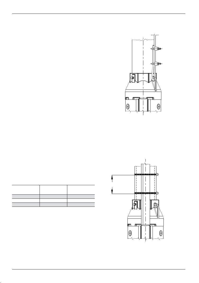
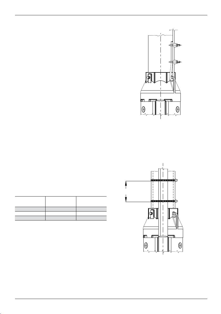
Quando si utilizzano tubi in plastica, assicurare la pompa
appaiono sulla targhetta motore da conservare nel
con una fune non in tensione collegata alla bocca di
quadro elettrico.
mandata, come in Fig. 3.
Il motore deve essere messo a terra e collegato
al quadro elettrico.
m
4.2 Controllo del senso di rotazione
Una volta collegata all’alimentazione elettrica,
determinare il senso di rotazione come segue:
1. Avviare la pompa e controllare la prevalenza fornita
con saracinesca non completamente chiusa.
2. Fermare la pompa e scambiare i collegamenti di due
fasi.
3. Avviare la pompa e ripetere il punto 1 con saracinesca
nella stessa posizione.
4. Fermare la pompa.
Confrontare i risultati ottenuti dopo aver eseguito i punti 1
e 3. Il collegamento corretto è quello che da la massima
prevalenza.
Nota: La pompa non può essere avviata no a che il
supporto di aspirazione non è stato completamente
sommerso.
5. INSTALLAZIONE DELLA POMPA
Prima di iniziare qualsiasi lavoro sulla pompa
o sul motore assicurarsi di aver disinserito
m
l’alimentazione elettrica e che non possa essere
reinserita accidentalmente.
5.1 Assemblaggio della pompa con Motore
Posizionare la pompa sul motore in modo che siano
sullo stesso asse e inserire l'albero motore nel giunto
dell'albero pompa senza che l'accoppiamento risulti
forzato.
Serrare le viti o dadi che ssano le ange pompa-motore
diagonalmente con una coppia di serraggio come indicato
nella tabella sottostante.
Coppia di
Tipo motore Vite
serraggio Nm
Motore 4" M8 18
Motore 6" M12 100
Motore 8" M16 200
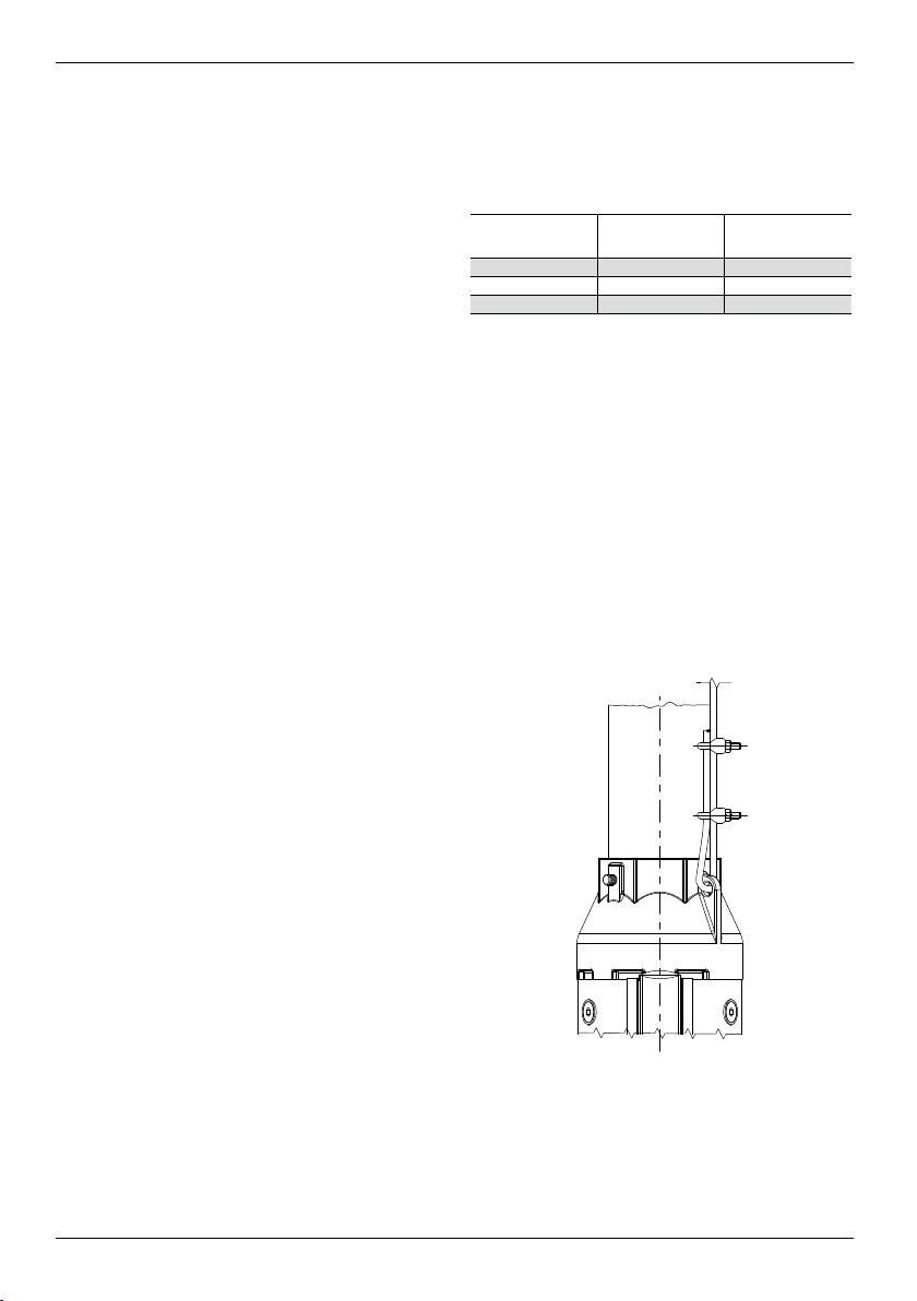
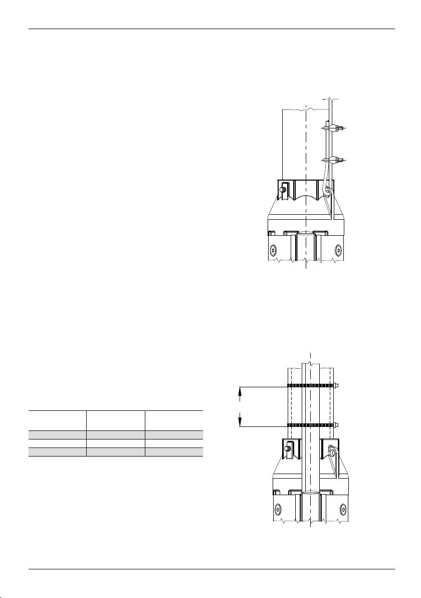
5.2 Tubazione di mandata
Se la pompa è già accoppiata alla tubazione di mandata
e si usa una chiave a catena per tubi, la pompa dovrà
essere stretta solo afferrandola per la bocca di mandata.
I tubi lettati dovranno essere collegati in modo da
contenere l’azione a svitare dovuta all’avviamento/
arresto della pompa.
Il letto del tubo che si avvita alla pompa non deve essere
più lungo del letto della pompa.
Dopo l'avvitamento del tubo nella bocca di mandata
serrare la vite posta per impedire l'allentamento del primo
tratto di tubazione, vedi Fig. 3.
5
00114016 09/2008
00114016 06/2010
Fig. 3
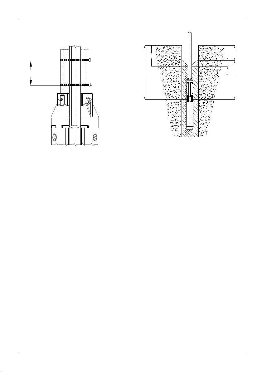
5.3 Sistemazione del cavo
Per ssare il cavo sulla fune di sostegno o sulla tubazione
di mandata bisogna usare delle fascette da posizionare
ogni 3 metri.
Usare delle fascette in plastica come indicato in Fig. 4.
Una volta fermato il cavo, tagliate la sporgenza della
fascetta.
3mt
3mt
00114019 09/2008
00114019 06/2010
Fig. 4
Nel caso che il tubo sia di plastica, bisogna lasciare il
cavo elettrico e la fune di sostegno non in tensione onde
evitare che l’allungamento del tubo, dovuto al peso
dell’acqua in esso contenuto, strappi il cavo elettrico.
Con tubi angiati le fascette dovranno essere applicate
prima e dopo le ange.
5.4 Inserimento della pompa
Si raccomanda di vericare che il pozzo non sia ostruito
per tutta la sua lunghezza.
Calate la pompa nel pozzo evitando di danneggiare il
cavo elettrico.
Nota: Non utilizzate il cavo elettrico per calare la pompa.
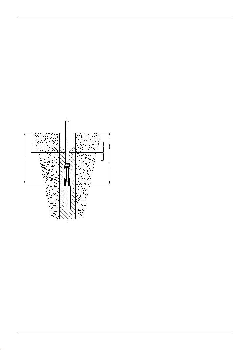
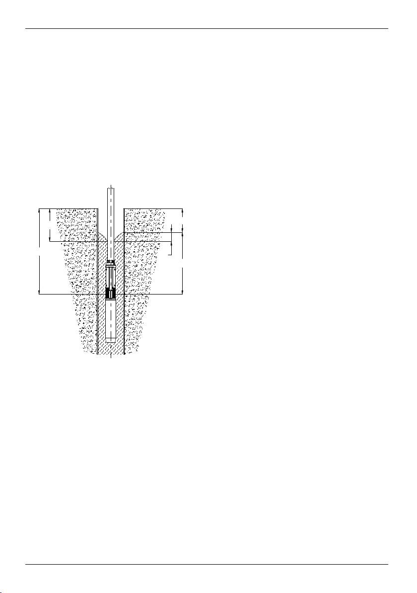
5.5 Profondità di installazione
Il livello dinamico nel pozzo deve garantire la copertura
del supporto di aspirazione della pompa, vedere
paragrafo 3.1 Limiti di posizionamento e Fig. 5.
Il margine minimo di sicurezza deve essere di 1 metro.
6
Lb
Lc
Lt
Ld
La
Lb
Lc
Lt
Ld
La
00114015 09/2008
Se ci sono impurità nell’acqua bisognerà aprire
gradualmente la saracinesca no a che l’acqua comincerà
a schiarirsi. La pompa non deve essere fermata prima
che l’acqua sia tornata completamente pulita, perché
altrimenti le varie parti della pompa e la valvola di non
ritorno potrebbero rovinarsi.
Se la portata della pompa è superiore a quella del
pozzo, raccomandiamo l’uso di una apparecchiatura che
protegge contro la marcia a secco.
In assenza di ogni protezione contro la marcia a secco, il
livello dell’acqua scenderà sotto il supporto aspirazione e
la pompa aspirerà aria.
Ciò, a lungo andare, provocherà danni per insufciente
raffreddamento e lubricazione.
7. MANUTENZIONE E ASSISTENZA
Le pompe non richiedono particolari manutenzioni.
Tutte le pompe sono facili da manutentare.
Utilizzate i Service Kits e gli attrezzi speciali per la
manutenzione.
Il Manuale Assistenza è disponibile su richiesta.
Prima di iniziare qualsiasi lavoro sulla pompa
o sul motore assicurarsi di aver disinserito
m
l’alimentazione elettrica e che non possa essere
reinserita accidentalmente.
8. SMALTIMENTO
Lo smaltimento di questo prodotto, o parte di esso, deve
essere effettuato usando i sistemi locali, pubblici o privati,
di raccolta dei riuti.
00114015 06/2010
Fig. 5
La: Profondità minima di installazione.
È raccomandata al minimo 1 mt.
Lb: Livello statico dell’acqua.
Lc: Livello dinamico dell’ acqua
Ld: Differenza tra livello statico e dinamico
Lt: Profondità di installazione.
Bloccate il tubo di mandata con apposite staffe sulla testa
del pozzo.
Allentate la fune di sostegno ed assicuratela alla
fondazione.
6. AVVIAMENTO
Una volta installata e sommersa, si può avviare la pompa
con la saracinesca chiusa di 1/3.
Controllare il senso di rotazione come descritto al
paragrafo 4.2 Controllo del senso di rotazione.

9. RICERCA GUASTI
●
Portata nulla
●
Portata insufciente
●
Pressione insufciente
●
La pompa si avvia e si ferma troppo frequentemente
●
Eccessiva corrente assorbita dall'elettropompa
Possibili cause imputabili alla pompa
Soluzione
(Escluso il motore e il quadro)
██ █ Abbassamento eccessivo del livello del pozzo Attendere il ripristino del livello o, se possibile,
abbassare la pompa
██ Griglia in aspirazione intasata Estrarre il gruppo e pulire
██ Valvola in mandata chiusa o bloccata Ricercare la valvola difettosa e sostituirla
█ █ Pompa insabbiata Estrarre il gruppo, sbloccare la pompa
██ █ Senso di rotazione errato Eseguire quanto riportato al punto 4.2
█ █ Capacità pompa troppo elevata rispetto a quella del
Sostituire la pompa con un'altra di minor
pozzo
capacità
█ Perdite nell'impianto Localizzare le perdite e riparare
█ Pompa usurata Estrarre la pompa e revisionarla
█ Interruttore di pressione o di livello mal regolati Regolare la taratura
█ Serbatoio troppo piccolo Sostituire il serbatoio con un altro di maggior
capacità
█ Attriti meccanici Estrarre la pompa e revisionarla
7

• hazard of electrical, mechanical or chemical nature.
ï EN ð
Safety regulations
These operating instructions contain relevant information
All safety instructions contained in this manual shall be
and precautionary notes. Please read the manual
observed, as well as any other national regulation on
carefully before assembling, electrical connection and
accident prevention, and any internal regulation on the
commissioning.
use of machineries and on occupational safety.
General Observations
Safety instructions for control, maintenance, and
This pump has been developed according to the
operation works
most advanced and recent technology, as well as in
The person in charge must verify that all maintenance,
compliance with the regulations in force. Moreover, the
inspection and installation works are performed by
pump is subject to a permanent quality control.
qualied and authorised personnel. Before performing
These operating instructions are intended to help you
these works, the personnel must be aware of the content
better understand the pump operation and to show you
of this manual.
its possible applications.
All interventions on the machines must be carried out
The manual contains important information necessary
only during total standstill of the mentioned machines.
for reliable and protable operation. Compliance with the
Strictly observe the shutdown procedure described in this
operating instructions is of vital importance to ensure the
manual.
reliability and a long service life of the pump, as well as to
Pumps conveying uids hazardous to health must be
avoid any accident risk due to improper use.
decontaminated.
This pump must not be operated beyond the limit values
Immediately after completion of work, all safety and
quoted in the technical specication. Any indication
protective devices must be re-installed and/or re-enabled.
concerning the nature, the density, the temperature, and
the rate ow of the pumped liquid, as well as the rotation
Modication and manufacture of Spare parts
speed, the pressure and the power of the motor shall be
Any reconstruction or alteration of the machine must
observed. Any other instruction contained in this manual
be performed by the manufacturer before being carried
or in the documentation enclosed to the agreement shall
out. Original spare parts and accessories supplied by
be observed as well.
the manufacturer ensure safety. The manufacturer is not
The rating plate bears the type series, the main
in any case liable for damages due to the use of non-
operation data, and the serial number. Please, quote this
original spare parts!
information in all request of intervention or assistance,
and when ordering spare parts.
1. DELIVERY AND STORAGE
Safety regulations
1.1 Delivery
This manual contains essential instructions that must be
These submersible pumps are supplied in their own
observed during installation, operation and maintenance.
original packing in which they should remain until
Therefore, this operating handbook must be read and
installation.
understood both by the person in charge of assembling
Avoid the pump to be bent when it is not packed, since
the machine and by all qualied personnel appointed by
this may cause the misalignment and the damage of the
the responsible for installation to perform its operation.
pump itself.
These operating instructions must always be available on
The loose data plate supplied with the pump should be
use site of the machine.
xed close to the electric control equipment.
The pump shall not be exposed to unnecessary impacts
Marking of coded instructions within the manual
and crashes.
The safety instructions contained in this manual, whose
inobservance might cause hazards to person, are marked
1.2 Storage and Handling
with the general hazard sign, i.e.:
Storage Temperature:
(hazard sign)
Pump: from -20°C to +60°C
m
The pump should not be exposed to direct sunlight.
If the pump has not been packed, it shall be stored
Risks due to inobservance of safety instructions
horizontally, adequately supported, or vertically, to
Inobservance of safety instructions may cause physical
prevent the misalignment of the pump. During storage,
and material damages, as well as environmental pollution.
the pump can be supported as shown in Fig. 1.
Non-compliance with safety instructions will also lead to
the complete loss of any warranty right.
In particular, the inobservance of the above mentioned
instructions may for example result in:
• failure of main machine/unit functions;
• failure of maintenance procedures;
8
9
00114017 09/2008
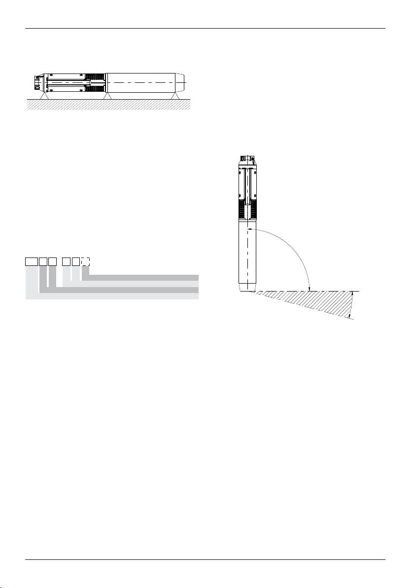
The pump is suitable for both vertical and horizontal
installation, however, the pump should never be installed
inclined downwards, see Fig. 2.
Note: During operation, the suction support must always
be completely submerged.
00114017 06/2010
In special conditions, it may be necessary to submerge
Fig. 1
the pump even deeper, depending on the operation
conditions of the pump, as well as on temperature and
If the pump is not used in vertical position, both the pump
NPSH values.
side and the motor side must be supported. Note that the
centre of gravity will vary according to the pump type.
2. GENERAL DATA
2.1 General description
The submersible pumps are multistage pumps working
with counterclockwise rotation direction (observing from
the delivery side) directly coupled to special submersible
motors (according to NEMA standards).
Pump identication code
2.2 Applications
These submersible pumps are designed for a wide range
of applications, such as the supply of water to private
homes, water systems and industries.
These pumps are necessary in case of lowering of the
groundwater level, as well as for pressure increase.
Submerge the pump completely under the water level
both if it is installed horizontally and vertically. See
paragraph 3.1 Positioning Limits.
2.3 Pumped liquids
Pumped liquids must be clean, compatible with pump
components and materials, without solid particles or
bres.
The maximum sand content in the water must not exceed
50 g/m³. A greater sand content in the water reduces the
service life of the pump and increases the risk of blocking.
When pumping liquids with a density higher than that of
water, motors with correspondingly higher outputs must
be used.
3. INSTALLATION / PREPARATION
3.1 Positioning limits
If the pump has to be installed in a position
where it is accessible to people, any possibility
m
of contact with the coupling must be avoided.
The pump might for instance be equipped with a
protective shield.
00114018 09/2008
Version completely in AISI 316
Number of stages
Rated flow rate m³/h
00114018 06/2010
Fig. 2
3.2 Diameter of Pump/Motor
Check in the technical catalog the maximum diameter of
the pump and the pump with motor.
Verify the borehole with an inside calliper to ensure
unobstructed passage.
3.3 Check valve on the delivering piping
The pump is equipped with an embedded check valve
in the delivery opening. However, it is recommended,
especially if the pump directly feeds a distribution network
subject to pressure, to install another check valve on
the delivery piping at no more than 10 meters from the
minimum well level. (If this latter is not known, use the
delivery opening as minimum level).
Its presence reduces hydraulic shocks due to starts and
stops.
4. ELECTRICAL CONNECTIONS
Before starting to work on the pump, make sure
that the power supply has been disabled and
m
that it cannot be accidentally switched on.
4.1 General remarks
The electrical connections should be carried out by an
authorised electrician according to the regulations in
... 7 N
Type of pump
/
... 7 N
/
8
1 5
8
1 5
... 7 N
8
/
1 5
... 7 N
8
/
1 5
... 7 N
8
/
1 5
... 7 N
8
/
1 5
... 7 N
8
/
1 5
... 7 N
8
/
1 5
... 7 N
8
/
1 5
... 7 N
8
/
1 5
... 7 N
8
/
1 5
... 7 N
8
/
1 5
... 7 N
8
/
1 5
... 7 N
8
/
1 5
Versione completamente in AISI 316
Version vollkommen aus AISI 316
Version complètement en AISI 316
Versiòn completamente en AISI 316
Wersja wykonana całkowicie ze stali AISI 316
Версия полностью из AISI 316
Version fuldstændigt i AISI 316
Versio AISI 316
Έκδοση πλήρης από AISI 316
Versie volledig van AISI 316
Komplett versjon i AISI 316
Versão completamente em AISI 316
Version helt i AISI 316
Numero di stadi
Stufennummer
Numéro de stages
Nùmero de estadios
Liczba stopni
Количество ступеней
Antal trin
Vaiheiden määrä
Αριθμός βαθμιδών
Aantal trappen
Antall stadier
Número de estágios
Antal steg
Portata nominale m³/h
Nenndurchfluss m³/h
Débit nominal m³/h
Capacidad nominal m³/h
Przepływ znamionowy m³/h
Номинальный расход, м³/ч
Nominel flowhastighed m³/h
Nimellinen tilavuusvirta m³/h
Μετρώμενος ρυθμός ροής m³/h
Nominale stromingssnelheid m³/u
Rangert pumpeytelse m³/h
Taxa do caudal nominal m³/h
Nominell flödeshastighet m³/h
Tipo di pompa
Pumpentyp
Type de pompe
Tipo de bomba
Rodzaj pompy
Тип насоса
Pumpetype
Pumpun tyyppi
Τύπος αντλίας
Type pomp
Type pumpe
Tipo de bomba
Typ av pump
force.
delivery opening, see Fig. 3.
Supply voltage, current and cos φ are quoted on the
motor plate that has to be kept within the electrical panel.
The motor must be earthed and connected to
the electric panel.
m
4.2 Verication of Rotation Direction
When the pump has been connected to the power supply,
establish the current direction of rotation as follows:
1. Start the pump and control the head provided with
gate valve not fully closed.
2. Stop the pump and interchange two of the phase
connections.
3. Start the pump and repeat step 1. with the gate valve
in the same position.
4. Stop the pump.
Compare the results obtained after performing steps 1
and 3. The correct connection is the one that gives the
highest head.
Note: The pump must not be started until the suction
support has been completely submerged.
5. PUMP INSTALLATION
Before starting any work on the pump or on the
motor, make sure that the power supply has
m
been disabled and that it cannot be accidentally
switched on.
5.1 Assembling of the pump with the motor
Place the pump on the motor in order that they are
positioned along the same axis and insert the motor shaft
in the pump shaft joint: the coupling must not be forced.
Tighten the screws or the nuts that diagonally x the
pump-motor anges with a driving torque as quoted in
the following table.
Driving torque
Motor type Screw
Nm
Motor 4" M8 18
Motor 6" M12 100
Motor 8" M16 200
5.2 Delivery piping
If the pump is already coupled to the delivery piping and
you use a chain pipe wrench, tighten the pump, holding it
only by the delivery opening.
The threaded pipes must be connected in such a way as
to support the unscrewing action due to the starting and
stopping of the pump.
The thread of the pipe, which has to be screwed into the
pump, should not be longer than the thread of the pump.
After screwing the pipe into the delivery opening, tighten
the screw assembled to avoid the loosening of the rst
section of the pipe, see Fig. 3.
When plastic pipes are used, the pump should be
secured by an unloaded rope to be fastened to the
10
00114016 09/2008
00114016 06/2010
Fig. 3
5.3 Cable tting
Use cable clips every 3 meters to x the cable to the
support rope or to the delivery pipe.
Use plastic cable clips as shown in Fig. 4.
Once the cable has been fastened, cut off the remaining
part of the clip.
3mt
3mt
00114019 09/2008
00114019 06/2010
Fig. 4
In the case that the tube is plastic, it must leave the
electric cable and the cable support not in tension to
prevent the elongation of the tube, due to the weight of
the water contained in it, tearing the electric cable.
When anged pipes are used, the cable clips must be
positioned before and after each ange.
5.4 Lowering of the pump
Verify that the well is not clogged along its total length.
Lower the pump into the well, paying attention not to
damage the electric cable.
Note: Do not lower the pump by means of the electric
cable.
5.5 Installation depth
The dynamic water level must always be above the
suction support of the pump, see paragraph 3.1
Positioning Limits and Fig. 5.
The minimum safety margin shall be 1 meter.
11
Lb
Lc
Lt
Ld
La
Lb
Lc
Lt
Ld
La
00114015 09/2008
clean again, since otherwise the pump parts and the non-
return valve may be damaged.
If the pump ow rate is higher than that of the well,
the use of a protection device against dry operation is
recommended.
Without any protection against dry operation, the water
level falls under the suction support and the pump sucks
air. In the long term, this causes damages due to poor
cooling and lubrication.
7. MAINTENANCE AND SERVICE
The pumps are maintenance-free.
All pumps are easy to service.
Use the Service Kits and the special tools for maintenance.
The Service Manual is available upon request.
Before performing any operation on the pump
or on the motor, verify that the power supply
m
is disabled and that it cannot accidentally be
enabled again.
8. DISPOSAL
This product or parts of it must be disposed using the
local public or private waste collection service.
00114015 06/2010
Fig. 5
La: Minimum installation depth
(suggested: minimum 1 mt).
Lb: Static water level
Lc: Dynamic water level
Ld: Difference between static and dynamic level
Lt: Installation depth
Block the delivery pipe with proper hangers on the well
head.
Loosen the support rope and x it to the groundwork.
6. START-UP
When the pump has been installed and submerged, it can
be started with the gate valve closed to 1/3.
Check the direction of rotation as described in section 4.2
Verication of Rotation Direction.
If there are impurities in the water, the gate valve should
be opened gradually until the water becomes clearer. The
pump should not be stopped until the water is completely
9. TROUBLESHOOTING
●
Zero ow rate
●
Poor ow rate
●
Poor pressure
●
The pump starts and stops too frequently
●
Excessive current absorbed by the electro-pump
Possible causes related to the pump
Solution
(Motor and panel excluded)
██ █ Well water level too low Wait until well water level is restored, or if
possible, lower the pump further
██ Suction screen clogged Pull out the assembly and clean it
██ Delivery valve closed or blocked Find and replace the defective valve
█ █ Pump silted up Pull out the assembly and clean it
██ █ Wrong direction of rotation Carry out instructions as in 4.2
█ █ Pump capacity exceeds well capacity Replace pump with one of lower capacity
█ Leaks in the system Locate leaks and repair them
█ Worn pump Pull out the assembly and overhaul it
█ Pressure switch or level control improperly set Adjust setting
█ Tank too small Replace tank with a larger one
█ Mechanical friction Pull out the pump and overhaul it
12

Risiken wegen Missachtung der
ï DE ð
Sicherheitsvorschriften
Die Missachtung der Sicherheitsvorschriften kann
Diese Betriebsanweisungen beinhalten wichtige
physische und Sachschaden, als auch möglicherweise
Informationen und Anweisungen. Wir bitten Sie darum,
Umweltverschmutzung verursachen. Die Missachtung
sie vor der Montage, der Ausführung der elektrischen
der Sicherheitsvorschriften kann zum vollkommenen
Schaltung und der Ingangsetzung sorgfältig zu lesen.
Verlust der Garantierechte führen.
Zum Beispiel, kann die Missachtung der obererwähnten
Allgemeine Bemerkungen
Vorschriften unter anderen folgende Ereignisse
Die Pumpe wurde nach der fortgeschrittensten und
verursachen:
neusten Technik und unter voller Beachtung der
• den Ausfall der grundsätzlichen Maschinen- oder
geltenden Regelungen erzeugt, und sie wird ständig auf
Ausrüstungsfunktionen;
ihre Qualität geprüft.
• die Beeinträchtigung der Wartungsvorgänge;
Das gegenständliche Handbuch wir Ihnen beim Verstehen
• körperschaden elektrischer, mechanischer oder
der Pumpenbetriebweise von Hilfe sein und wir Ihnen die
chemischer Natur.
möglichen Anwendungen der selben zeigen.
Das Gebrauchshandbuch beinhaltet wichtige
Sicherheitsvorschriften
Anweisungen über den richtigen und preisgünstigen
Alle im gegenständlichen Handbuch enthaltenen
Betrieb der Pumpe. Es ist zwangsmäßig, diese
Sicherheitsanweisungen, als auch alle nationalen
Anweisungen zu beachten, um die Zuverlässigkeit und
Gesetzvorschriften über Unfallverhütung und alle inneren
die Lebensdauer der Maschine zu gewährleisten, und um
Regelungen über die Verwendung der Ausrüstungen und
Unfallrisiken wegen Missbrauches zu vermeiden.
über die Sicherheit am Arbeitsplatz, müssen beachtet
Die Pumpe muss nicht außerhalb der im technischen
werden.
Protokoll beschriebenen Grenzen angewandt werden. Es
ist notwendig, die Anwesungen über die Natur, die Dichte,
Sicherheitsanweisungen für Kontroll-, Wartungs-
die Temperatur und den Durchuss der gepumpten
und Bedienungseingriffe
Flüssigkeit, als auch die Drehungsgeschwindigkeit, die
Der Verantwortliche muss prüfen, dass alle Wartungs-,
Motorleistung, und alle anderen in diesem Handbuch
Prüfungs- und Montagevorgänge von qualiziertem
oder in den dem Vertrag beigelegenen Unterlagen
und autorisiertem Personal ausgeführt werden. Vor der
enthaltenen Anweisungen zu beachten.
Ausführung dieser Vorgänge ist es notwendig, dass
Der kleine Schild gibt die Serie, die allgemeinen
dieses Personal den Inhalt dieses Handbuches kennt.
Betriebsangaben und die Seriennummer an.
Im allgemeinen sind alle Eingriffe an den Maschinen
Es ist wichtig, diese Angaben bei Eingriff- oder
nur bei Gesamtausschaltung der genannten
Kundendienstanforderungen, als auch bei der Bestellung
Maschinen auszuführen. Es ist absolut notwendig,
von Ersatzteilen mitzuteilen.
das im gegenständlichen Handbuch enthaltenen
Haltensverfahren zu beachten.
Sicherheitsvorschriften
Die Pumpen, welche gesundheitsgefährdende
Das gegenständliche Handbuch enthält grundsätzliche
Flüssigkeiten fördern, müssen entgiftet werden.
Anweisungen, welche während der Installation, des
Am Ende der Arbeiten sind alle Sicherheits- und
Betriebs und der Wartung zu beachten sind. Das
Schutzvorrichtungen wieder anzumontieren und in
gegenständliche Handbuch muss zwangsmäßig
Betrieb zu setzten.
vom für die Montage zuständigen Bediener, als auch
vom qualizierten vom Aufstellungsverantwortlichen
Änderung und Erzeugung von Ersatzteilen seitens
bestimmten Personal gelesen werden, das den Betrieb
des Kunden
ausführen wird. Außerdem muss das gegenständliche
Der Wiederaufbau oder die Änderung der Maschine
Handbuch immer bei der Verwendung der Maschine zur
muss vorher immer vom Hersteller genehmigt werden.
Verfügung stehen.
Die vom Hersteller gelieferten Originalersatzteile und
Zubehörteile gewährleisten die Sicherheit. Der Hersteller
Identikation der codierten Anweisungen im
ist keinesfalls für die Folgen von der Verwendung von
gegenständlichen Handbuch
nicht-originalen Ersatzteilen verantwortlich!
Die im gegenständlichen Handbuch enthaltenen
Sicherheitsvorschriften, deren Missachtung physische
1. LIEFERUNG UND LAGERUNG
Schaden verursachen kann, sind vom allgemeinen
Gefahrsymbol gekennzeichnet.
1.1 Lieferung
(Sicherheitssymbol)
Die Tauchpumpen werden in ihrer Originalverpackung
geliefert, in der sie bis zur Aufstellung bleiben müssen.
m
Darauf Acht geben, dass die Pumpe nicht gebogen
wird, wenn sie nicht mehr verpackt ist: das könnte den
Fluchtungsfehler und die Beschädigung der Pumpe
selbst verursachen.
13
Der nicht aufgetragene Schild, der zusammen mit
der Pumpe geliefert wird, ist neben der elektrischen
Steuerungsausrüstung zu befestigen.
Die Pumpe nutzlos nicht stoßen oder reiben.
1.2 Lagerung und Transport
Lagerungstemperatur:
Pumpe: von -20°C bis +60°C
Die Pumpe muss nicht den Sonnenstrahlen ausgesetzt
werden.
Wenn die Pumpe nicht verpackt worden ist, ist sie
waagerecht und auf zweckmäßige Weise gestützt im
Lager aufzubewahren, um eventuellen Fluchtungsfehler
zu verhüten. Während der Lagerung kann die Pumpe laut
Abbildung 1 gestützt werden.
14
00114017 09/2008
2.3 Gepumpten Flüssigkeiten
Saubere, mit den Pumpenbaustoffen kompatible
Flüssigkeiten ohne feste Teilchen oder Fasern.
Der maximale Gehalt an Sand im Wasser muss 50 g/
m³ nicht überschreiten. Eine höhere Sandkonzentration
wird die Lebensdauer der Pumpe verringern und den
Sperregefahr steigern.
Wenn die Pumpe angewandt wird, um Flüssigkeiten
mit einer höheren Wasserdichte zu pumpen, ist es
notwendig, einen Motor mit einer proportional höheren
Leistung anzuwenden.
3. AUFSTELLUNG / AUFBEREITUNG
3.1 Positionierungsgrenzen
Wenn die Pumpe in einem der Personen
zugänglichen Raum aufgestellt wird, ist
m
jede Möglichkeit von Berührung zwischen
Verbindungsstück und Leuten – eventuell
durch die Anwendung eines Schutzschildes zu
00114017 06/2010
vermeiden.
Abb. 1
Die Pumpe ist sowohl für die senkrechte, als auch für die
waagerechte Aufstellung geeignet. Die Pumpe ist nie mit
Wenn die Pumpe nicht senkrecht angewandt wird, muss
einer Neigung nach unten aufzustellen, Abb. 2.
man sowohl die Pumpe als auch den Motor stützen.
Es ist zu bemerken, dass der Schwerpunkt nach der
Anmerkung: Während des Betriebs muss die
Pumpensorte ändert.
Absaugstütze immer getaucht sein. Unter sonderbaren
Umständen kann es notwendig sein, sie mehr nach unten
2. ALLGEMEINE ANGABEN
nach dem Arbeitspunkt, den Temperaturen und NPSH
der Pumpe eingetaucht werden.
2.1 Allgemeine Beschreibung
Die Multistufen-Tauchpumpen sind Pumpen, welche
mit einem linksgängigen Drehsinn (wenn man sie aus
der Druckseite beobachtet) unmittelbar an sonderbare
Unterwassermotoren (laut NEMA Standard) gekuppelt
arbeiten.
Pumpeidentikationscode
2.2 Anwendungen
Diese Tauchpumpen sind für eine breite Reihe
von Anwendungen entworfen worden, wie
die Wasserversorgung für Privatwohnungen,
Wasserfernleitungen und Werkstätten. Sie sind sowohl
im Falle von Senkung des Grundwasserspiegels, als
auch für Druckanstieg unentbehrlich.
Die Pumpe vollkommen unter dem Wasserstand
eintauchen, wenn sie sowohl waagerecht als
auch senkrecht aufgestellt wird. Siehe Absatz 3.1
Positionierungsgrenzen.
00114018 09/2008
00114018 06/2010
Abb. 2
3.2 Pumpe/Motor-Durchmesser
Überprüfen Sie im technischen Katalog der maximale
Durchmesser der Pumpe und der Pumpe mit dem Motor.
Prüfen, dass der Schacht keine Beschränkungen oder
Hindernisse zum Abwärtsgang der Pumpe aufweist.
... 7 N
/
8
1 5
Version completely in AISI 316
Number of stages
Rated flow rate m³/h
Type of pump
Version vollkommen aus AISI 316
Stufennummer
Nenndurchfluss m³/h
... 7 N
Pumpentyp
/
... 7 N
/
8
1 5
8
1 5
... 7 N
8
/
1 5
... 7 N
8
/
1 5
... 7 N
8
/
1 5
... 7 N
8
/
1 5
... 7 N
8
/
1 5
... 7 N
8
/
1 5
... 7 N
8
/
1 5
... 7 N
8
/
1 5
... 7 N
8
/
1 5
... 7 N
8
/
1 5
... 7 N
8
/
1 5
Versione completamente in AISI 316
Version complètement en AISI 316
Versiòn completamente en AISI 316
Wersja wykonana całkowicie ze stali AISI 316
Версия полностью из AISI 316
Version fuldstændigt i AISI 316
Versio AISI 316
Έκδοση πλήρης από AISI 316
Versie volledig van AISI 316
Komplett versjon i AISI 316
Versão completamente em AISI 316
Version helt i AISI 316
Numero di stadi
Numéro de stages
Nùmero de estadios
Liczba stopni
Количество ступеней
Antal trin
Vaiheiden määrä
Αριθμός βαθμιδών
Aantal trappen
Antall stadier
Número de estágios
Antal steg
Portata nominale m³/h
Débit nominal m³/h
Capacidad nominal m³/h
Przepływ znamionowy m³/h
Номинальный расход, м³/ч
Nominel flowhastighed m³/h
Nimellinen tilavuusvirta m³/h
Μετρώμενος ρυθμός ροής m³/h
Nominale stromingssnelheid m³/u
Rangert pumpeytelse m³/h
Taxa do caudal nominal m³/h
Nominell flödeshastighet m³/h
Tipo di pompa
Type de pompe
Tipo de bomba
Rodzaj pompy
Тип насоса
Pumpetype
Pumpun tyyppi
Τύπος αντλίας
Type pomp
Type pumpe
Tipo de bomba
Typ av pump
3.3
Rückschlagventil an der vorlaufrohrleitung
Pumpenwellekupplung einführen, ohne dabei eine
Presspassung zu schaffen.
Die Pumpe ist mit einem eingebetteten Rückschlagventil
Die Schrauben oder die Muttern anziehen, welche
in der Vorlaufmündung versehen. Es ist auf jeden Fall
diagonal die Pumpe-Motor-Flanschen mit einem
ratsam, besonders im Falle von Anwendungen, bei denen
Befestigungsdrehmoment laut unterliegender Tabelle
die Pumpe ein Druckverteilungsnetz unmittelbar versorgt,
befestigen.
ein anderes Rückschlagventil in der Vorlaufrohrleitung
an nicht mehr als 10 Meter vom Brunnenmindeststand
Befestigungs-
zu installieren. (Ist der Mindeststand nicht bekannt, die
Motortyp Schraube
Drehmoment Nm
Vorlaufmündung als Mindeststand verwenden).
Die Anwesenheit dieser Vorrichtung begrenzt die
Motor 4" M8 18
hydraulischen Schocks wegen Starts und Stopps.
Motor 6" M12 100
Motor 8" M16 200
4. ELEKTRISCHE VERBINDUNGEN
5.2 Vorlaufrohrleitung
Vor jedem Eingriff an der Pumpe prüfen, dass
Wenn die Pumpe schon mit der Vorlaufrohrleitung
die Stromversorgung getrennt worden ist und
gekuppelt ist und man einen Ketten-Rohrschlüssel
m
dass sie zufällig nicht wieder angeschlossen
anwendet, muss die Pumpe nur derart angezogen
wird.
werden, indem man sie beim Druckausgang faßt.
Die geschnittenen Röhren müssen derart verbunden
4.1 Allgemeine Betrachtungen
werden, dass sie die Abschraubenswirkung begrenzen,
welche vom Starten/Halten der Pumpe verursacht ist.
Die Verbindungen sind von einem nach den geltenden
Der Gewindegang, der sich an der Pumpe einschraubt,
Regelungen autorisierten Elektriker auszuführen. Die
muss nicht länger als des Gewindeganges der Pumpe
Stromversorgungsspannung, der Strom und cos φ sind
sein.
auf dem Motorschild angegeben, der im Schaltschrank
Nach dem Anschrauben des Rohres am Druckausgang,
aufzubewahren ist.
die Schraube anziehen, welche aufgestellt ist, um das
Der Motor muss beerdet und zum Schaltschrank
Lösen der ersten Rührungsstrecke zu vermeiden, siehe
verbunden werden.
Abb. 3.
m
Wenn Kunststoffröhren angewandt sind, die Pumpe
4.2 Drehsinnkontrolle
mit einem spannungsfrei mit dem Druckausgang
verbundenen Seil sichern, siehe Abb. 3.
Nachdem man die elektrische Stromversorgung
verbunden hat, den Drehsinn folgendermaßen
bestimmen:
1. Die Pumpe starten und die bei nicht vollkommen
geschlossenem Schieber gelieferte Förderhöhe
prüfen.
2. Die Pumpe halten und die Verbindungen von zwei
Phasen tauschen.
3. Die Pumpe starten und den Schritt 1 mit dem Schieber
in der selben Stellung ausführen.
4. Die Pumpe halten.
Die nach der Ausführung der Schritte 1 und 3 erhaltenen
Ergebnisse vergleichen. Die richtige Verbindung ist
diejenige, welche die höchste Förderhöhe aufweist.
Anmerkung: Die Pumpe kann solange nicht gestartet
werden, bis die Absaugstütze nicht vollkommen
eingetaucht worden ist.
5. AUFSTELLUNG DER PUMPE
Vor jedem Eingriff an der Pumpe oder am
Motor prüfen, die Stromversorgung getrennt zu
m
haben, als auch dass sie zufällig nicht wieder
verbunden wird.
5.1 Montage der Pumpe am Motor
Die Pumpe auf den Motor derart stellen, dass sie sich
auf der selben Achse benden. Die Motorwelle in die
15
00114016 09/2008
00114016 06/2010
Abb. 3
5.3 Kabelaufstellung
Um das Kabel am Stützseil oder an der Vorlaufrohrleitung
zu befestigen, Schellen anwenden, die alle 3 Meter zu
positionieren sind.
Kunststoffschellen laut Abb.4 anwenden.
Wenn das Kabel befestigt worden ist, den Überstand der
Schelle schneiden.
16
3mt
3mt
00114019 09/2008
00114019 06/2010
Abb. 4
Sollte die Rohrleitung aus Kunststoff bestehen, das
elektrische Kabel und das Stützseil spannungsfrei lassen,
um zu vermeiden, dass die Ausdehnung des Kabels
wegen des im Rohr enthaltenen Wassergewichtes das
elektrische Kabel reißt.
Bei Flanschrohren sind die Schellen vor und nach den
Flanschen anzubringen.
5.4 Einführung der Pumpe
Prüfen, dass der Schacht seine ganze Länge lang nicht
verstopft ist.
Die Pumpe in den Schacht abseilen, und dabei
vermeiden, das elektrische Kabel zu beschädigen.
Anmerkung: Um die Pumpe abzuseilen, nicht das
elektrische Kabel anwenden.
5.5 Aufstellungstiefe
Das dynamische Niveau im Schacht muss die Deckung
der Pumpenabsaugstütze gewährleisten - siehe Absatz
3.1 Positionierungsgrenzen und Abb. 5.
Die Mindestsicherheitsgrenze beträgt 1 Meter.
Lb
Lc
Lt
Ld
La
Lb
Lc
Lt
Ld
La
00114015 09/2008
00114015 06/2010
Abb. 5
La: Aufstellungsmindesttiefe. Es wird eine
Tiefe von mindestens 1 m empfohlen.
Lb: statischer Wasserstand
Lc: dynamischer Wasserstand
Ld: Unterschied zwischen statischem und
dynamischen Stand
Lt: Aufstellungstiefe.
Das Druckrohr mit zweckmäßigen Bügeln am
Schachtkopf verriegeln.
Das Stützseil lösen und es am Fundament befestigen.
6. STARTEN
Nachdem die Pumpe aufgestellt und eingetaucht worden
ist, kann man die Pumpe mit dem um 1/3 geschlossenen
Schieber starten.
Den Drehsinn laut Absatz 4.2 Drehsinnkontrolle prüfen.
Wenn es Unreinheiten im Wasser gibt, den Schieber
schrittweise solange öffnen, bis das Wasser fängt an,
sich aufzuhellen. Die Pumpe ist solange nicht zu halten,
bis das Wasser wieder vollkommen sauber geworden
ist, denn anderenfalls könnten sich die verschiedenen
Pumpenteilen und das Rückschlagventil beschädigen.
Wenn die Fördermenge der Pumpe die des Schachtes
nicht überschreitet, wird die Anwendung einer Ausrüstung
empfohlen, welche gegen den Trockengang schützt.
In Abwesenheit jeder Schutzvorrichtung gegen den
Trockenbetrieb sinkt der Wasserstand unter der
Absaugstütze und die Pumpe wird Luft absaugen.
Im Laufe der Zeit wird das Schaden wegen ungenügender
Kühlung und Schmierung verursachen.
7. WARTUNG UND SERVICE
Die Pumpen erfordern keine besondere Wartung.
Alle Pumpen sind einfach in Stand zu halten.

Wenden Sie die Service Kits und die
8. ENTSORGUNG
Wartungssonderwerkzeuge an. Das Service-Handbuch
Die Entsorgung dieses Produktes, oder von Teilen des
steht auf Anfrage zur Verfügung.
selben, ist nach den lokalen, öffentlichen oder privaten
Vor jedem Eingriff an der Pumpe oder am Motor
Abfallsammlungssystemen auszuführen.
prüfen, dass die Stromversorgung getrennt
m
worden ist, und dass sie zufällig nicht wieder
verbunden werden kann.
9. STÖRUNGSBEHEBUNG
●
Keine Fördermenge
●
Ungenügende Fördermenge
●
Ungenügender Druck
●
Die Pumpe startet und haltet sich zu oft
●
Übertriebener von der Elektropumpe aufgenommener Strom
Mögliche Ursachen, die von der Pumpe abhängen
Lösung
(Motor und Schalttafel ausgeschlossen)
██ █ Übertriebene Senkung des Schachtniveaus Auf die Standwiederherstellung warten, oder die
Pumpe, falls möglich, niedriger stellen
██ Absauggitter verstopft Den Satz herausziehen und ihn reinigen
██ Druckventil geschlossen oder verriegelt Das fehlerhafte Ventil suchen und es wechseln
█ █ Besandte Pumpe Den Satz herausziehen - die Pumpe entriegeln
██ █ Falscher Drehsinn Punkt 4.2 ausführen
█ █ Zu hohe Pumpenleistung im Vergleich zur
Die Pumpe mit einer anderen mit einer kleineren
Schachtkapazität
Kapazität wechseln
█ Verluste im Rahmen der Anlage Die Verluste lokalisieren und sie beheben
█ Verschleißte Pumpe Die Pumpe herausziehen und sie überholen
█ Druck- oder Standschalter falsch geregelt Die Eichung regeln
█ Behälter zu klein Den Behälter mit einem anderen mit größerer
Kapazität wechseln
█ Mechanische Reibungen Die Pumpe herausziehen und sie überholen
17

• panne dans les fonctions principales de la machine ou
ï FR ð
de l'installation,
• compromission des opérations d'entretien,
Ces instructions pour l'exercice contiennent d'importantes
• dommages au corps du type électrique, mécanique ou
indications et avertissements. Nous vous prions de les
chimique.
lire avant du montage, de la connexion électrique et de
la mise en marche.
Normes de sécurité
Toutes les instructions de sécurité présentes dans
Généralité
ce manuel doivent être respectées, ainsi que les
La pompe a été réalisée selon les techniques les plus
prescriptions de la loi, nationales en matière de
avancées et récentes, dans le plein respect des normes
préventions des accidents et les règles internes d'emploi
en vigueur et elle est soumise à un contrôle de qualité
des installations et de sécurité sur le travail.
permanent.
Ce manuel va vous aider dans la compréhension du
Instructions de sécurité pour les travaux de contrôle,
fonctionnement de la pompe et dans la connaissance de
entretien et service
ses possibles applications.
Le responsable doit vérier que tous les travaux
Le manuel pour l'emploi contient des recommandations
d'entretien, d'inspection et de montage soient réalisés
nécessaires pour le fonctionnement correct et
par personnel qualié et autorisé. Avant de passer à ces
économique de la pompe. Il faut respecter ces
travaux, il faut que ce personnel soit à connaissance du
recommandations, dans le but de garantir la abilité, la
contenu de ce manuel.
durée et éviter ainsi les risques d'accident dérivant d'un
En général, tous les travaux sur les machines doivent
emploi non approprié.
être réalisées uniquement sous arrêt complet de ces
On ne doit pas utiliser la pompe hors des limites décrites
machines. Il est absolument nécessaire de respecter la
dans les spécications techniques. Il faut respecter
procédure décrite dans ce manuel.
les indications concernant la nature, la densité, la
Les pompes véhiculant des uides dangereux pour la
température, le débit du liquide pompé, la vitesse de
santé doivent être decontaminées.
rotation, la pression, la puissance du moteur et toutes
À la n des travaux, tous les dispositifs de sécurité et
les autres instructions contenues dans ce manuel ou la
de protection doivent être remontés et remis en fonction.
documentation en annexe au contrat.
La plaquette indique la gamme, les spécications
Modication et fabrication des pièces de rechange
principales de service et le numéro de série. Il est
faites par le client
important de fournir ces indications au moment de
La reconstruction ou modication de la machine doit
la demande d'intervention ou d'assistance et pour
être toujours approuvée par le constructeur avant
commander les pièces de rechange.
d'être réalisée. Les pièces de rechange originales et
les accessoires fournis par le constructeur garantissent
Normes de sécurité
la sécurité. Le constructeur ne sera en aucun cas
Ce manuel contient des instructions fondamentales à
responsable des conséquences dérivant de l'emploi des
respecter au moment de l'installation, emploi et entretien.
pièces de rechange non originales!
Ce manuel doit obligatoirement être consulté par le
responsable du montage et par tout le personnel qualié
1. LIVRAISON ET EMMAGASINAGE
suivant le fonctionnement, désigné par le responsable
des installations. Aussi, ce manuel doit être toujours à
1.1 Livraison
disposition dans le lieu d'emploi de la machine.
Les pompes submersibles sont fournies dans leur
emballage original dans lequel doivent rester jusqu'au
Identication des instructions codiées de ce manuel
moment de l'installation.
Les normes de sécurité contenues dans ce manuel,
Il faut faire attention de ne pas soumettre la pompe à
dont la non observance peut causer des dommages
une exion quand elle n'est plus emballée: cela pourrait
physiques, sont marquées par le symbole général de
causer la sortie de l'axe et l'endommagement de la
danger.
pompe même.
(symbole de danger)
La plaquette non appliquée qui est fournie avec la pompe,
doit être xée près de l'appareil électrique de commande.
m
La pompe ne doit pas être exposée à des coups et
Risques dérivant de la faute de respect des normes
collisions.
de sécurité
La faute de respect des normes de sécurité peut
1.2 Emmagasinage et mouvement
provoquer des dommages physiques et matériaux, au
delà de la possible pollution de l'environnement. La non
Température d'emmagasinage:
observance des normes de sécurité peut porter à la perte
Pompes: de -20°C à +60°C
totale des droits de garantie.
La pompe ne doit pas être exposée aux rayons solaires.
Pour mentionner quelque exemple, la faute de respect de
Si la pompe n'a pas été emballée, on doit la conserver
ces normes peut provoquer:
dans le magasin horizontalement, bien soutenue pour
18
prévenir la possible sortie de l'axe. Pendant le stockage,
la pompe peut être soutenue comme indiqué dans la
gure 1.
19
00114017 09/2008
Si la pompe est installée dans une position
accessible aux personnes, il faut éviter toute
m
possibilité de contact entre joint et personnes,
par exemple en l'équipant avec un écran de
protection.
La pompe est adaptée pour l'installation soit verticale que
horizontale, jamais avec inclinaison vers le bas, Fig. 2.
00114017 06/2010
Note: Pendant le fonctionnement, le support d'aspiration
Fig. 1
doit toujours être submergé.
En conditions spéciales il peut être nécessaire le
Si la pompe n'est pas utilisée dans la position verticale,
submerger plus à fond en fonction du point de travail,
il faut soutenir soit la partie de la pompe que le moteur.
températures et NPSH de la pompe.
Il faut remarquer que le barycentre varie selon le type
de pompe.
2. DONNÉES GÉNÉRALES
2.1 Description générale
Les pompes submersibles sont des pompes multistage
fonctionnant avec sens de rotation antihoraire (en les
observant du côté de débit) directement couplées à des
moteurs spéciaux (selon la norme NEMA) submersibles.
Code de identication pompe
2.2 Applications
Ces pompes submersibles ont été projetées
pour une vaste gamme de applications, comme
l'approvisionnement hydrique pour habitations privées,
pour aqueducs et industries. Indispensable en cas de
réduction du niveau de nappe et pour l'augmentation de
pression.
Introduire la pompe complètement sous le niveau
de l'eau quand vous l'installez, soit horizontalement
que verticalement. Voir paragraphe 3.1 Limite de
positionnement.
2.3 Liquides pompés
Liquides propres, compatibles avec les matériaux
constructifs de la pompe, sans particules solides ou
bres.
Le contenu maximum de sable dans l'eau ne doit pas
dépasser 50 g/m³. Une plus grande concentration de
sable réduit la vie de la pompe et augmente le risque
de bloc.
Si la pompe est utilisée pour pomper des liquides avec
une densité supérieure à l'eau, il faut utiliser un moteur
avec une puissance proportionnellement plus grande.
3. INSTALLATION / PRÉPARATION
3.1 Limites de positionnement
00114018 09/2008
00114018 06/2010
Fig. 2
3.2 Diamètre de pompe/moteur
Vériez dans le catalogue technique le diamètre maximal
de la pompe et de la pompe avec le moteur.
Vérier que le puit ne présente pas des restrictions ou
des obstacles pour la descente de la pompe.
3.3 Vanne d'arret sur la tuyauterie de
refoulement
La pompe incorpore une vanne d'arrêt dans la bouche
de refoulement. On conseille cependant, spécialement
dans les applications dans lesquelles la pompe alimente
directement un réseau de distribution en pression,
d'installer une autre vanne d'arrêt sur la tuyauterie
de refoulement à non plus de 10 mètres dès le niveau
minimum du puits ( si on ne le connaît pas, il faut utiliser
la bouche de refoulement comme niveau minimum).
Sa présence réduit les chocs hydrauliques dus aux
démarrages et aux arrêts.
4. CONNEXIONS ÉLECTRIQUES
Avant de commencer à travailler sur la pompe, il faut
s'assurer de avoir débranché la connexion électrique
m
et qu'elle ne soit pas reconnectée par hasard.
... 7 N
/
8
1 5
... 7 N
/
8
1 5
Version completely in AISI 316
Version vollkommen aus AISI 316
Number of stages
Stufennummer
Rated flow rate m³/h
Nenndurchfluss m³/h
Type of pump
Pumpentyp
Version complètement en AISI 316
Numéro de stages
Débit nominal m³/h
... 7 N
Type de pompe
/
... 7 N
/
8
1 5
8
1 5
... 7 N
8
/
1 5
... 7 N
8
/
1 5
... 7 N
8
/
1 5
... 7 N
8
/
1 5
... 7 N
8
/
1 5
... 7 N
8
/
1 5
... 7 N
8
/
1 5
... 7 N
8
/
1 5
... 7 N
8
/
1 5
... 7 N
8
/
1 5
Versione completamente in AISI 316
Versiòn completamente en AISI 316
Wersja wykonana całkowicie ze stali AISI 316
Версия полностью из AISI 316
Version fuldstændigt i AISI 316
Versio AISI 316
Έκδοση πλήρης από AISI 316
Versie volledig van AISI 316
Komplett versjon i AISI 316
Versão completamente em AISI 316
Version helt i AISI 316
Numero di stadi
Nùmero de estadios
Liczba stopni
Количество ступеней
Antal trin
Vaiheiden määrä
Αριθμός βαθμιδών
Aantal trappen
Antall stadier
Número de estágios
Antal steg
Portata nominale m³/h
Capacidad nominal m³/h
Przepływ znamionowy m³/h
Номинальный расход, м³/ч
Nominel flowhastighed m³/h
Nimellinen tilavuusvirta m³/h
Μετρώμενος ρυθμός ροής m³/h
Nominale stromingssnelheid m³/u
Rangert pumpeytelse m³/h
Taxa do caudal nominal m³/h
Nominell flödeshastighet m³/h
Tipo di pompa
Tipo de bomba
Rodzaj pompy
Тип насоса
Pumpetype
Pumpun tyyppi
Τύπος αντλίας
Type pomp
Type pumpe
Tipo de bomba
Typ av pump
4.1 Généralité
Après le vissage du tuyau dans la bouche de débit, il faut
serrer la vis placée pour empêcher l'affaiblissement du
Les connexions doivent être réalisées par un électricien
premier segment de tuyauterie, voir Fig. 3.
autorisé selon les règles en vigueur.
Quand on utilise des tuyaux en plastique, il faut xer la
La tension de alimentation, le courant et le cos φ
pompe avec une corde pas en tension connectée à la
apparaissent sur la plaquette moteur à garder dans le
bouche de débit, comme dans la Fig. 3.
panneau électrique.
On doit brancher le moteur à terre et le
connecter au panneau électrique.
m
4.2 Contrôle du sens de rotation
Une fois connectée à l'alimentation électrique, il faut
déterminer le sens de rotation comme suit:
1. Démarrer la pompe et contrôler la prévalence fournie
avec le robinet pas encore fermé.
2. Arrêter la pompe et échanger les connexions des
deux phases.
3. Démarrer la pompe et répéter le point 1 avec le
robinet dans la même position.
4. Arrêter la pompe.
Comparer les résultats obtenus après avoir réalisé les
points 1 et 3. La connexion correcte est celle donnant le
maximum de prévalence.
Nota: La pompe ne peut pas être démarrée jusqu'à ce
que le support de aspiration n'a pas été complètement
submergé.
5. INSTALLATION DE LA POMPE
Avant de commencer tout travail sur la pompe
ou sur le moteur il faut s'assurer de avoir
m
débranché l'alimentation électrique et qu'on ne
risque pas de la rebrancher par hasard.
5.1 Assemblage de la pompe avec moteur
Positionner la pompe sur le moteur de façon qu'ils soient
sur le même axe et introduire l'arbre moteur dans le joint
de l'arbre de la pompe, sans que le couplage soit forcé.
Serrer les vis ou écrous qui xent les brides pompe-
moteur diagonalement avec un couple de serrage
comme indiqué dans la table ci-dessous.
Couple de
Type moteur Vis
serrage Nm
Moteur 4" M8 18
Moteur 6" M12 100
Moteur 8" M16 200
5.2 Tuyauterie de débit
Si la pompe est déjà couplée à la tuyauterie de débit et
on utilise une clef de chaîne pour tuyaux, on doit serrer la
pompe uniquement en la prenant par la bouche de débit.
Les tuyaux letés doivent être connectés de façon à
contenir l'action à dévisser, due au démarrage/arrêt de
la pompe.
Le let du tuyau qui se visse ne doit pas être plus long
que le let de la pompe.
20
00114016 09/2008
00114016 06/2010
Fig. 3
5.3 Arrangement du câble
Pour xer le câble sur la corde de soutien ou sur la
tuyauterie de débit il faut utiliser des bandes à positionner
tous les 3 mètres.
Utiliser des bandes en plastique comme indiqué en Fig.
4. Une fois arrêté le câble, couper la saillie de la bande.
3mt
3mt
00114019 09/2008
00114019 06/2010
Fig. 4
