Ridgid CountPlus: instruction
Class: Power tools
Type:
Manual for Ridgid CountPlus
CountPlus
GB p. 1
DE p. 11
FR p. 21
NL p. 31
IT p. 41
ES p. 51
PT p. 61
SV p. 71
DA p. 81
NO p. 91
FI p. 101
HR p. 111
PL p. 121
RO p. 131
CZ p. 141
HU p. 151
GR p. 161
RU p. 171
TR p. 181
SL p. 191
RID 085-210-024.10
RIDGE TOOL COMPANY
Tools For The Professional
TM
cover_manualcountplus-letter.ind3 3 22/04/2009 17:08:49

cover_manualcountplus-letter.ind4 4 22/04/2009 17:08:49
Ridge Tool Company
1
Tools For The Professional
TM
®
SEESNAKE
COUNTPLUS CABLE-COUNTER
General Safety Information
GB
WARNING
®
SeeSnake
CountPlus Cable Counter
Read and understand all instructions. Failure to follow instructions listed
Operator’s Manual
below may result in electric shock, re, and/or serious personal injury!
Work Area Safety
WARNING! Read this operator’s manual
• Keep your work area clean and well lit. Cluttered benches and dark
carefully before using this tool. Failure
areas may cause accidents.
to understand and follow the contents
• Do not operate electrical devices or power tools in explosive at-
of this manual may result in electrical
mospheres, such as in the presence of ammable liquids, gases, or
shock, re and/or serious personal injury.
heavy dust. Electrical devices or power tools create sparks, which may
ignite the dust or fumes.
• Keep bystanders, children, and visitors away while operating tool.
Safety Symbols
Distractions can cause you to lose control.
In this operator’s manual safety symbols and signal words are used to
Electrical Safety
communicate important safety information. This section is provided to improve
• Do not operate the system with electrical components removed.
understanding of these signal words and symbols.
Exposure to internal parts increases the risk of injury.
• Avoid exposure to rain or wet conditions. Keep battery out of direct
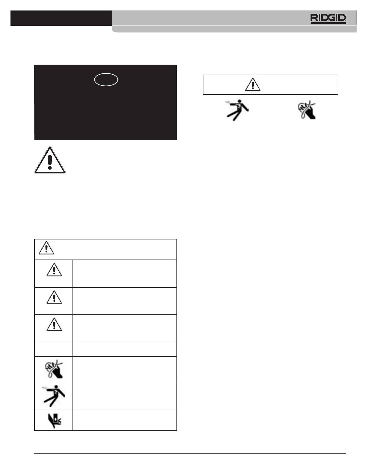
This is the safety alert symbol. It is used to alert you to potential
contact with water. Water entering electrical devices increases the risk of
personal injury hazards. Obey all safety messages that follow
electric shock.
this symbol to avoid possible injury or death.
• Do not probe high voltage lines.
DANGER indicates a hazardous situation which, if not
Battery Precautions
avoided, will result in death or serious injury.
• Use only the size and type of battery specied to avoid damage to
DANGER
electronics.
• Properly dispose of the batteries. Exposure to high temperatures
WARNING indicates a hazardous situation which, if not
can cause the battery to explode, so do not dispose of in a re. Some
avoided, could result in death or serious injury.
countries have regulations concerning battery disposal. Please follow all
WARNING
applicable regulations.
CAUTION indicates a hazardous situation which, if not
Personal Safety
avoided, could result in minor or moderate injury.
• Stay alert, watch what you are doing, and use common sense. Do
CAUTION
not use diagnostic tools while tired or under the inuence of drugs, alco-
hol, or medications. A moment of inattention while operating diagnostic
NOTICE
NOTICE indicates information that relates to the
protection of property.
instruments may result in serious personal injury.
• Gloves should always be worn for health and safety reasons. Sewer
lines are unsanitary and may contain harmful bacteria and viruses.
This symbol indicates the risk of hands, ngers or other
• Do not overreach. Keep proper footing and balance at all times.
body parts being caught.
Proper footing and balance enables better control of the tool in unex-
pected situations.
• Use safety equipment. Always wear eye protection. Dust mask,
non-skid safety shoes, hardhat, or hearing protection must be used for
This symbol indicates risk of electric shock.
appropriate conditions.
• Prevent object and liquid entry. Never spill liquid of any kind on the
CountPlus. Liquid increases the risk of electrical shock and damage to
This symbol indicates risk of hands, ngers or other
the product.
parts being crushed.
• Avoid Trafc. Pay close attention to moving vehicles when using
on or near roadways. Wear visible clothing or reector vests. Such
precautions may prevent serious injury.
744_031-601_0A_RevA_Countplus_ma1 1 9/04/2009 10:27:28
2
Ridge Tool Company
Tools For The Professional
TM
®
SEESNAKE
COUNTPLUS CABLE-COUNTER
CountPlus Use and Care
Standard Equipment
• Use equipment only as directed. Do not operate a SeeSnake unless
Item Cat. #
you have read the owner’s manual and been trained in its use.
• CountPlus 31753
• Do not immerse the CountPlus in water. Store in a dry place. This will
reduce the risk of electric shock and instrument damage.
• Store idle equipment out of the reach of children and other
SAVE THESE INSTRUCTIONS!
untrained persons. Equipment is dangerous in the hands of untrained
users.
The manuals provided with this instrument must be kept with the instrument
• Maintain the instrument with care.
and made available to any operator of the instrument.
• Check for breakage of parts, and any other conditions that may
affect the SeeSnake and CountPlus operation. If damaged, have the
CountPlus Installation
instrument serviced before using. Many accidents are caused by poorly
If you are retro-tting the CountPlus to an existing SeeSnake unit, you will
maintained tools.
need to install it. Detailed instructions are included in Appendix A.
• Protect against excessive heat. The product should be situated away
from heat sources such as radiators, heat registers, stoves or other
Tool Inspection
products (including ampliers) that produce heat.
Service
WARNING
Have the CountPlus serviced only by qualied repair persons to ensure the
safety of the unit is maintained.
Description, Specications and
Standard Equipment
The CountPlus is an improved digital distance-measuring and text display
Daily before use, inspect the SeeSnake and the CountPlus to reduce
®
device which can be tted to any SeeSnake
Standard or Mini camera reel.
the risk of serious injury from electrical shock or physical injuries!
The CountPlus is installed under the axle on the closed face of the drum.
It measures distance by counting drum rotations as you push the camera
1. With the SeeSnake unplugged from the monitor unit, inspect the power
through a line. It is a replacement for the CountIR counter.
cord and plug for damage or modications. IF any damage or modica-
tion is found, do not use the tool until it has been properly repaired or
The CountPlus allows you to control on-screen features through a 9-key
replaced.
waterproof keypad. When recording video, any features displayed on the
2. Clean any oil or grease from the SeeSnake, especially from the frame, to
screen are also recorded.
prevent the unit from slipping from your grip when carrying or positioning
it.
Display Features
3. Inspect the SeeSnake for any broken, worn or missing, misaligned or
binding parts, or any other condition which might prevent safe, normal
Distance Total distance the camera has traveled in the line, or from any
operation. Make sure the cable drum rotates smoothly and the cable
selected point in the line.
drum friction lock works correctly. Inspect the cable for any signs of
Text Overlay allows you to write a text title or description for display on
breakage or extreme wear. Inspect the camera head connection and
any segment of the captured video.
ensure it is tight. If any problems are found, have them repaired before
using the SeeSnake.
Date/Time
provides alternatives in displaying the date, time, or both.
Specications
• Weight w/o battery 3.5 oz. (100 gm)
• Weight w/ battery 3.7 oz. (105 gm)
Dimensions
• Width 3.5” (8.5 cm)
• Height 3” (7.3 cm)
• Depth 1.6” (4 cm)
Power Source
• 1 x CR2450 3V coin-style battery
Operating Environment
• Temperature -4°F to 22°F (-20°C to 50°C)
• Humidity 5% to 95% RH
• Storage -4°F to 140°F(-20°C to 60°C)
744_031-601_0A_RevA_Countplus_ma2 2 9/04/2009 10:27:29
Ridge Tool Company
3
Tools For The Professional
TM
®
SEESNAKE
COUNTPLUS CABLE-COUNTER
Tool and Work Area Set-Up
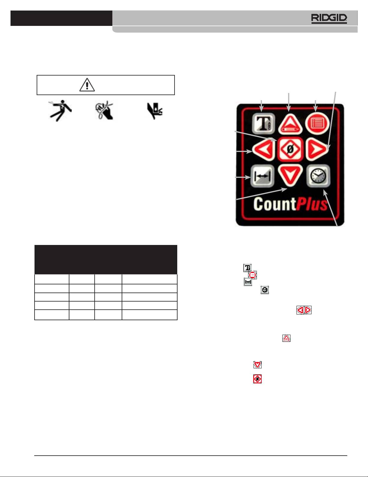
CountPlus Keys
WARNING
Up / Edit Arrow
Right Arrow
Text Key Menu / Back Key
Before use, setup the SeeSnake and work area safely to reduce the
Zero / Select Key
risk of injury from shock, re, crushing injuries or other causes and
prevent damage.
Left Arrow
1. Check work area for adequate lighting.
2. Check for a stable, level location to rmly position the SeeSnake where it
will be stable in operation.
3. Do not connect the SeeSnake power cord in the presence of ammable
Distance Key
liquids, vapors, or dust that may ignite.
4. Ensure there is a clear, level, dry place for the operator that allows him to
operate clear of the cable.
5. Ensure a clear path to a power outlet that does not contain any potential
Down Arrow
sources of damage to the power cord.
6. Use extension cords only if necessary. Use only cords rated for outside
use and of sufcient wire size.
Minimum Wire Gauge for Extension Cords
Time Key
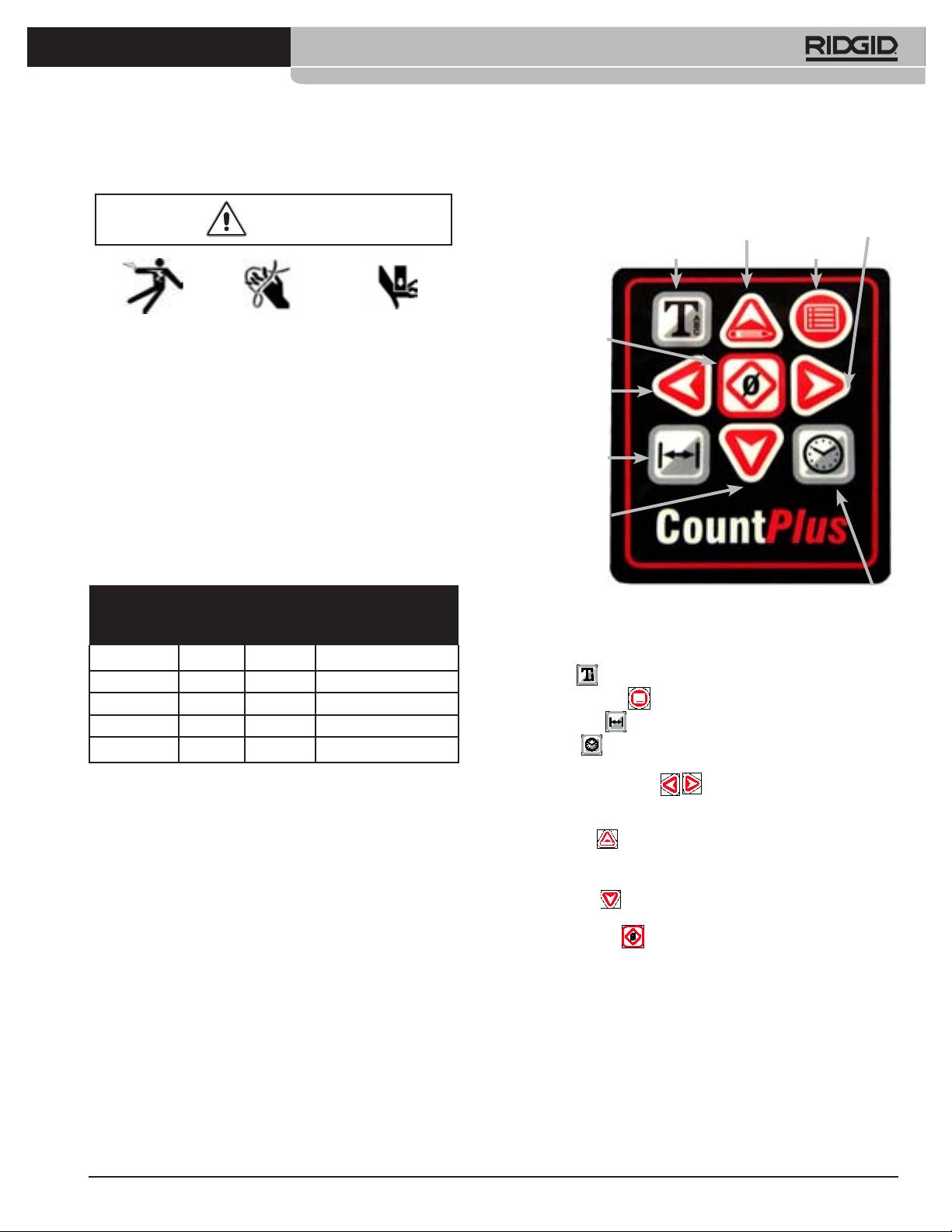
Figure 1: CountPlus Keypad
Nameplate
Total Length (in feet)
Amps
Keypad Description
0 – 25 26 – 50 51 – 100
The names of the keys are shown in Figure 1. Their functions are as follows.
0 – 6 18 AWG 16 AWG 16 AWG
Text Key
Toggles Text display on or off.
6 – 10 18 AWG 16 AWG 16 AWG
Menu / Back Key Opens the Main Menu.
10 – 12 16 AWG 16 AWG 14 AWG
Distance Key Toggles the distance measure display on or off.
12 – 16 14 AWG 12 AWG NOT RECOMMENDED
Time Key Toggles the date-time display to show date, time, none, or
both.
Left and Right Arrows
Move through available slides to
new slide if text is being displayed. Moves through menu choices and text
characters.
Up/Edit Key
Goes directly to the editing page for existing slides, if
slide text is being displayed when pressed. Moves through menu choices or
text characters.
Down Arrow
Moves through menu choices, values and text charac-
ters in edit mode.
Zero/Select Key
Selects a highlighted menu item; initializes the
local zero-point counter. A long press (> 3 seconds) will re-zero the default
distance counter.
744_031-601_0A_RevA_Countplus_ma3 3 9/04/2009 10:27:32
4
Ridge Tool Company
Tools For The Professional
TM
®
SEESNAKE
COUNTPLUS CABLE-COUNTER
System Settings
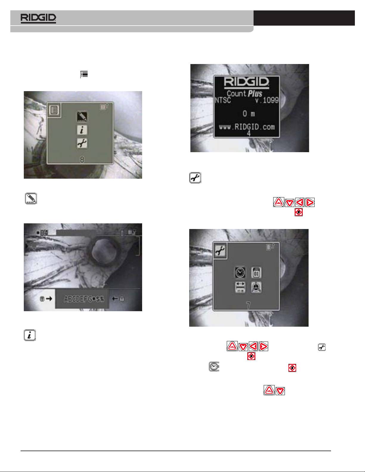
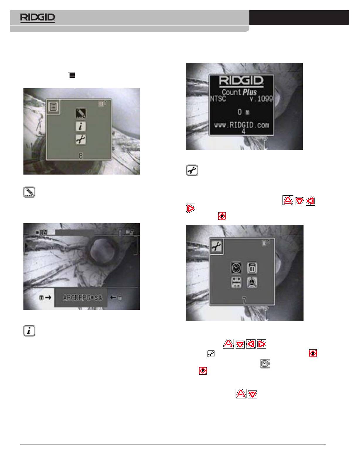
By pressing on the Menu Key , you will bring up the Main Menu screen
with three icons on it.
Figure 4: Information Screen
Tools Menu – Select this option to set the system date, time, the
Figure 2: Main Menu
reel and cable size and the units of measurement used.
Text Editing – Select this option to go directly to the slide editing
To choose one of the icons press Arrow Keys
to high-
menu from which you can select an existing slide for editing. Detailed instruc-
tions on editing titles and text content of slides can be found on Page 8.
light the icon of your choice. Press the Zero / Select Key
to activate the
choice.
Figure 3: Editing Screen
Figure 5: Tools Menu
Information Screen – This option will bring up an information
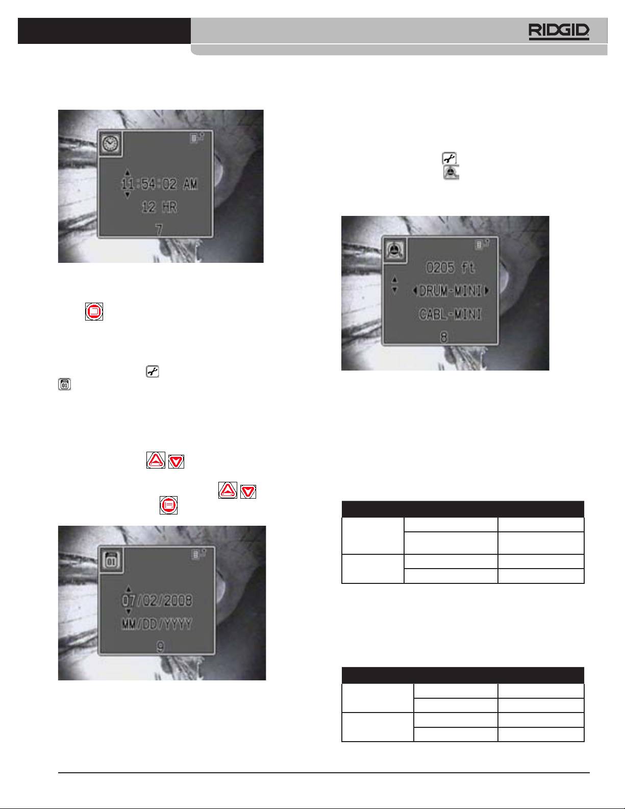
System Time
screen showing the software version installed in the CountPlus, the video
Use the Arrow Keys to scroll to the Tools icon ,
type (NTSC or PAL) it is congured for, and the total distance reading since
the unit was programmed.
and press the Zero/Select Key . In the sub-menu that appears, highlight
the Clock icon, and press the Zero/Select Key again. This will
bring up a menu showing the time format, hour, minute and second values,
and AM/PM options. Use the Arrow Keys to move to the item you want to
change, and use the up and down keys
to set it to your preferred
setting.
744_031-601_0A_RevA_Countplus_ma4 4 9/04/2009 10:27:40
Ridge Tool Company
5
Tools For The Professional
TM
®
SEESNAKE
COUNTPLUS CABLE-COUNTER
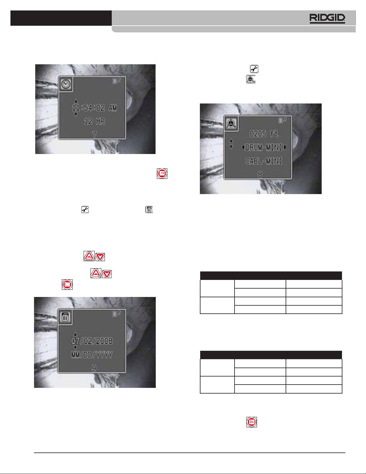
1. Select the Tools Menu .
2. Select the Reel icon .
3. Use the Up and Down arrows to move among the three parameters, and
the Right and Left Arrows to set their values.
Figure 6: System Time Screen
Format can be 12-hour time or 24-hour time. Press the Menu Key to
accept your settings and exit the menu. A timer will automatically exit the
menu after 10 seconds of no activity.
Figure 8: Reel and Cable Type Settings
System Date
Entering the Tools Menu and scrolling to the Calendar icon will
4. Arrow to the rst row (Cable Length) and press the Left and Right Arrow
bring up the System Date control panel. The display includes a format option,
Keys to increment the counter to the correct number of feet. To change
and a date string.
numbers more rapidly, hold down one of the arrow keys. The standard
lengths for Mini, and Standard SeeSnakes, as shipped, are shown in the
The format of the date display can be set to show the month, day and year
following table.
(MM/DD/YYYY) or to show the day, month and year (DD/MM/YYYY). Use
the arrow keys to highlight the month or day section of the format string, and
If your cable has been cut to some other total length adjust this to the
nearest 5 feet of its actual length.
press the Up or Down Key
to toggle the format between these
two choices. Use the arrow keys to highlight each value in the Date string
Table 1: Normal Cable Dimensions
and use the Up or Down Keys
to set the date correctly. Press
MINI STANDARD
Cable
0.36” 0.44”
the Menu Key to accept changes and escape from the Date menu.
Diameter
9.144 mm 11.176 mm
Cable
200‘ 100‘
Length
60.9 m 30.48 m
5. Arrow down to the second row and set the reel setting to Mini, Compact
or Standard to match the unit you are using. If you are not sure which
kind of reel you are using, the following measurements will help identify it:
Table 2: Normal Reel Dimensions
MINI STANDARD
Drum Inner
8.25” 11.82”
Radius
209.5 mm 300.2 mm
Drum Width 5” 6.76”
127 mm 171.7 mm
Figure 7: System Date Screen
6. Arrow down to the third row (Cable Setting). Use table 1 if needed to help
Reel and Cable Settings
identify the type of cable your system has in it.
Setting the right Reel and Cable types is part of setting up the CountPlus
7. Set the Cable Setting to the appropriate type installed in your SeeSnake.
to measure your particular SeeSnake correctly. When the CountPlus is
rst installed, it has to be congured for the reel size and cable type your
Press the Menu Key to save the settings and exit.
SeeSnake system is using (Mini or Standard).
744_031-601_0A_RevA_Countplus_ma5 5 9/04/2009 10:27:46
6
Ridge Tool Company
Tools For The Professional
TM
®
SEESNAKE
COUNTPLUS CABLE-COUNTER
This basic information should only need to be entered when rst setting up
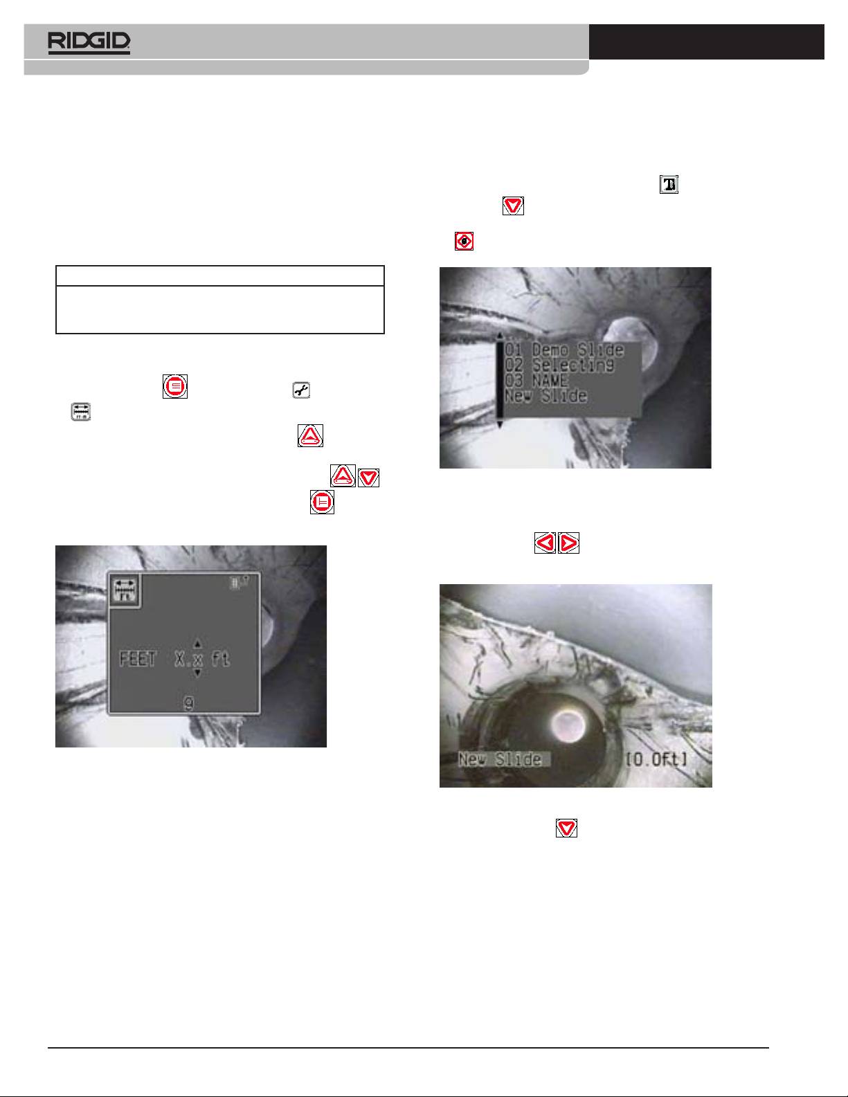
Creating a New Slide
the unit, unless it changes. If the measured count on the screen goes higher
To create a new slide for display:
than the set cable length, a + icon will precede the measurement on-screen.
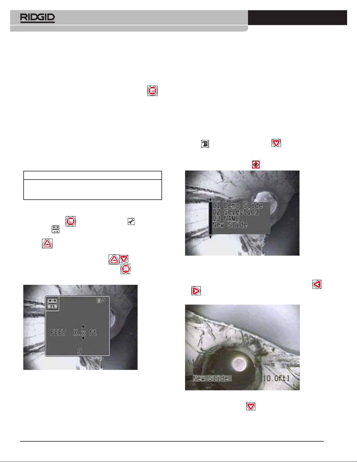
1) With text display toggled on using the Text Key , press the Down
Units of Measure
Arrow Key . A list of existing slides will appear with “New Slide” listed
The CountPlus can be set to report in feet and inches, or in meters. Several
at the bottom. Arrow down until “New Slide” is blinking, and press Select
formats are available in either measurement system.
.
Feet Meters
XX’ YY” X.xx m
XX ft YY in X.x m
XX.x ft
To set the preferred measurement units and format:
1. Press the Menu Key . Select the Tools Menu and then the
Measure menu .
2. Arrow to the left-hand column and use the Up Arrow to set the
choice to Feet or Meters.
Arrow to the right hand column and use the Up and Down Keys
Figure 10: Selecting the ‘New Slide’ Option
to select one of the available formats. Press the Menu Key to accept
2) A new slide will appear in Edit mode. The cursor will be in the Slide Title
the change and exit.
area. You can scroll through the characters of the title using the Left and
Right Arrow Keys
. You can add a title for the slide by select-
ing characters (see step 4 below).
Figure 9: Units of Measure Screen
The Reel setting for cable length and the distance measure on the screen
Figure 11: New Slide
will display in the units of measure selected.
Setting Up Text Slides
3) Press the Down Arrow to leave the Slide Title and enter the text
The CountPlus provides the ability to create titles and up to 6 lines of text
area. Use the arrow keys to locate the cursor where you want your text
for 20 different slides. These slides can then be used to title individual
to appear. Note: If you do not create a Title for the slide, the CountPlus
scenes or segments from the captured video. When a slide is displayed on
will use the rst ten characters of text from the body of the slide as a title.
the screen, any recording being done will include the text of that slide in the
This only occurs if the Title area is blank.
recorded frames.
The operator can choose several actions in order to have the slides appear
in a recording as he prefers.
1. Create a new slide for display.
2. Edit an existing slide.
3. Choose an existing slide for display.
4. Turn slide display on or off.
744_031-601_0A_RevA_Countplus_ma6 6 9/04/2009 10:27:54
Ridge Tool Company
7
Tools For The Professional
TM
®
SEESNAKE
COUNTPLUS CABLE-COUNTER
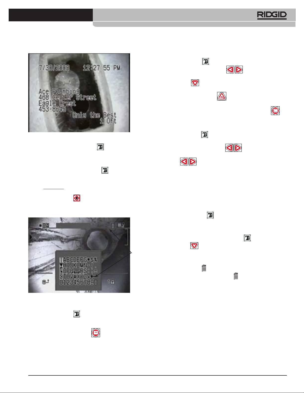
To Edit an Existing Slide
1) Press the Text Key to display the current slide’s text.
2) Use the Left and Right Arrow Keys to scroll through the
slides until the one you want to edit is displayed. Alternatively, press the
Down Arrow
to go through a list by title, and press Select when
your choice is highlighted.
3) Press the Up Arrow/Edit Key to enter the edit mode for the
displayed slide.
4) When you have made the desired changes, press the Menu Key
to exit the editing mode.
To Choose a Slide for Display
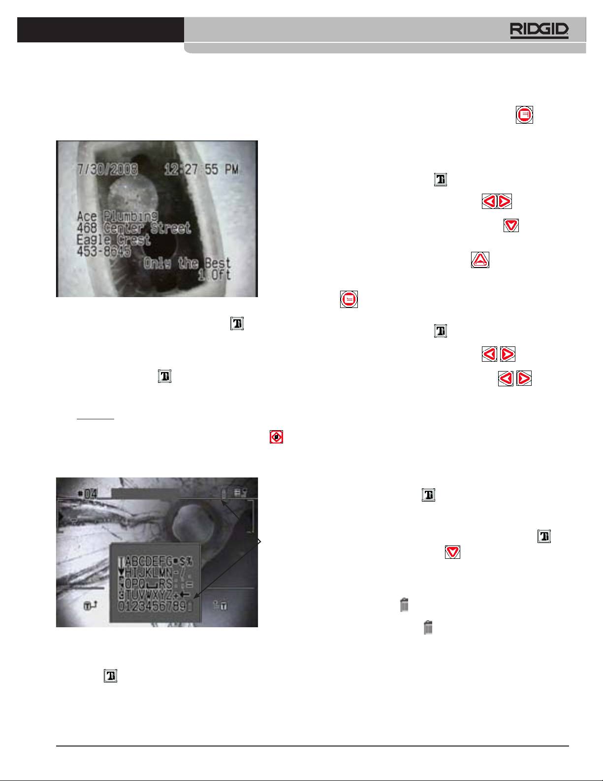
Figure 12: Slide Text Area
1) Press the Text Key to display the current slide’s text if it is not
displayed.
4) While you are in Edit mode, the Text Key will toggle between the
2) Use the Left and Right Arrow Keys to scroll through the slides
slide layout and the text selection screen.
until the one you want is displayed. Pressing the Left and Right Arrow
a. In the layout screen, use the Arrow Keys to move to any point in the
screen where you want to place characters. When you have located the
Keys
while a slide is displayed will change the display to the
next or previous slide in sequence.
cursor where you want it press the Text Key
to shift to the test se-
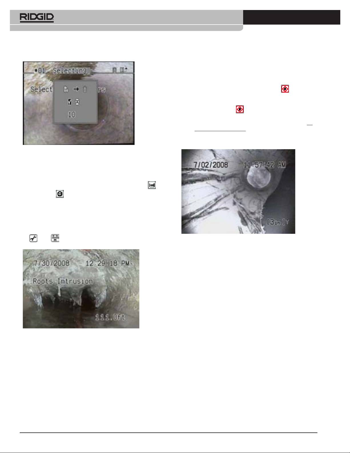
3) If you are recording a pipe inspection and want to change the slide
lection screen and actually write characters into the slide at that location.
overlay on the recording, pause the recording until you have selected
the desired slide, and then resume the inspection and the recording.
5) In the text selection screen, use the Arrow Keys to move to a desired
The displayed slide will be recorded along with the camera’s video. For
character, number, symbol, or backspace. When the desired item is
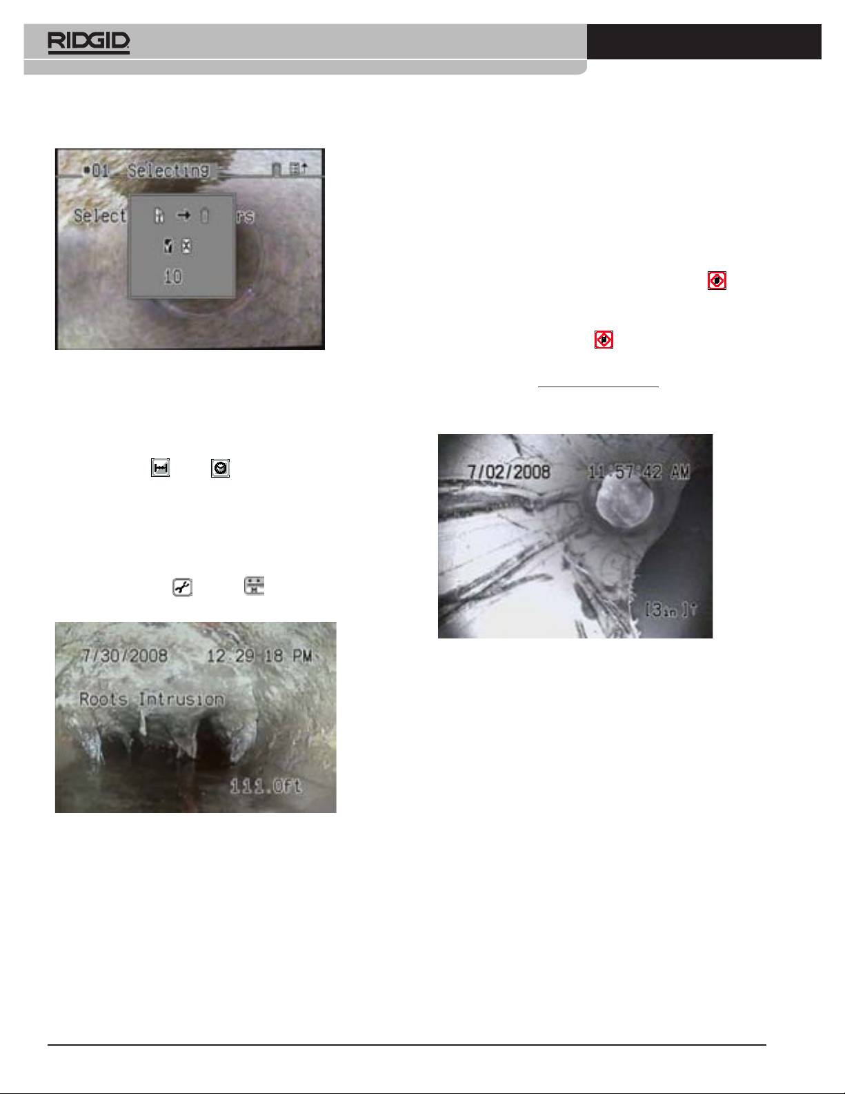
example, you may want to show an overlay that says “Roots” at the point
highlighted, press Select
to insert it onto the slide. Repeat for the
in the inspection where roots become evident.
next character, until the slide content is the way you want it. Note: The
backspace symbol () acts as a Delete key.
To Turn Slide Display On or Off
1) Pressing the Text Key will toggle the slide display off or on.
Deleting a Slide
To delete a text slide:
1. With text display toggled on using the Text Key , press the Down
Arrow Key . A list of existing slides will appear.
Trash
2. Arrow Down until the slide you wish to delete is highlighted and press the
Can
Select Key.
3. Use the Arrow Keys to move along the text area until the cursor is under
the Trash Can icon . In Figure 13, the Trash Can is to the right of the
Title area. Arrow up until the Trash icon blinks, and press the Select
Key. (Alternatively, you can Select the Trash Can at the end of the Text
characters – see Figure 13.).
4. A conrmation screen will appear. To delete the slide, highlight the check-
Figure 13: Text Selection Screen
mark icon and press Select. To cancel the deletion, highlight the X icon
and press Select, or simply press the Menu key.
a. To move to a different place in the slide, toggle back to the layout screen
by pressing the Text Key .
b. To edit the slide’s title, use the Arrow Keys to move into the Title Region.
Replace the default title with your preferred text.
c. To save a slide, press the Menu Key from the layout screen.
d. The slide will be saved automatically when you exit the slide, provided
some text has been entered on it.
744_031-601_0A_RevA_Countplus_ma7 7 9/04/2009 10:28:07
8
Ridge Tool Company
Tools For The Professional
TM
®
SEESNAKE
COUNTPLUS CABLE-COUNTER
Local” Zero-Point In addition, while it is operating, the CountPlus can be
made to also start counting from any custom “local zero-point” you select
with a second counter.
1) “To begin a separate distance count from a selected point, such as a
junction within a pipeline, press the Zero/Select Key briey. The dis-
tance display will re-set to [0.0]. The square brackets indicate that you
are measuring from a local zero-point rather than the system zero-point.
a) Pressing the Zero Key will now toggle the display between the
default count and the new [0.0] point.
b) Once you start measuring cable feed from a custom zero-point, do
not press the Zero Key again until you have completed the measure-
ment you are working on, as pressing it will reset the custom zero-
point again and lose the measurement you have been taking.
Figure 14: Conrm Deletion
CountPlus Operating Instructions
Basic Operation
With the SeeSnake connected and powered on, use the Distance Key
and the Time Key to set the display with the information you prefer.
a) The Time Key will toggle the display between Date, Date and Time, Time,
or No Date or Time displayed. Press the key once for each step through
the choices.
b) The Distance Key will toggle the display of distance on the screen
between on and off.
c) The distance counter will show the distance in the units set in the Tools
/Units menu (see Units of Measure above).
Figure 16: Measuring from a Custom Zero-Point
c) As a precaution you may want to write down the system measure-
ment’s initial value just before setting a new zero point. (This will
enable you to compute the distance manually using the system count,
if you reset the local zero-point accidentally).
2) The CountPlus will continue to count the distance the cable is extended
and display the current total (if the display of distance is toggled on) from
the system zero-point or from the current local zero-point, if one has been
set.
3) The system zero-point of the CountPlus may be reset to zero at any time
by a long press on the Zero/Select Key (greater than 3 seconds). All
future system counter measurements until power-down will be based on
this new system zero-point. This will also reset the local zero-point.
Figure 15: Display Screen with Slide Text, Time and Distance Shown
How the CountPlus Measures
(Distance measured from system zero-point)
Distance
The CountPlus uses the movement of two magnets embedded in the mount-
System Zero-Point and Local Zero Point
ing plate behind the CountPlus unit. The rotation of the cable reel causes
The counter, as shown in Figure 15, starts from zero when the system is
these magnets to change orientation relative to the CountPlus, and this
powered on. This is called the system zero-point. You can change the physi-
change is detected by Hall-effect sensors in the CountPlus. An embedded
cal point the system measures from by powering the system off, running the
computer uses these sensor responses to compute the linear distance, tak-
cable in or out to the desired zero point, and powering on from that point.
ing into account the size of the reel and the size and length of the cable.
The counter resets to zero when the system is powered on again.
The CountPlus sets its “system zero” reference point on powering up, follow-
ing a conguration check. For most accurate results the cable should be fully
Resetting the System Zero-Point You can reset this system zero point at
in the drum and the camera in the guide hoop when powering up. Otherwise,
anytime with a long press (> 3 seconds) on the Zero Key. It is good practice
varying degrees of slack in the extended cable can distort the measurement.
to do this, for example, at the entrance to a pipe.
744_031-601_0A_RevA_Countplus_ma8 8 9/04/2009 10:28:11
Ridge Tool Company
9
Tools For The Professional
TM
®
SEESNAKE
COUNTPLUS CABLE-COUNTER
Getting Consistent Measurements
The key to getting consistent measurements using the CountPlus is making
sure all the cable is in the reel before powering up the system. Wait for the
initialization screen to disappear before moving the camera head from the
guide hoop. This takes about 10 seconds.
Avoid moving the reel once you have started your measurements.
Make sure the cable length, cable diameter, and drum-size settings are cor-
rect for your system.
If the system is shut down or loses power for more than 10-20 seconds the
CountPlus may re-zero its system zero point of reference, and any local
zero-point count will be lost.
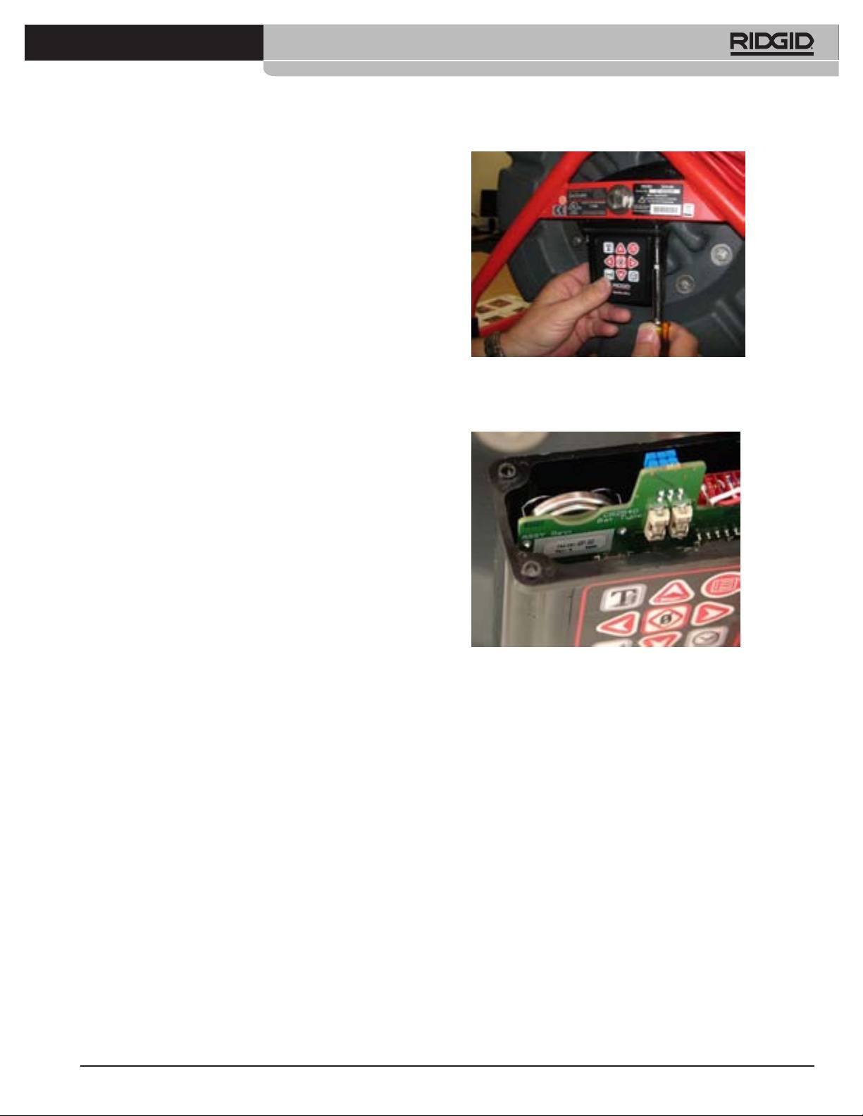
Figure 17: Removing the CountPlus
When spooling the cable into the drum, maintain a uniform friction or drag on
the cable to ensure it does not bunch up in the drum.
3. As you lower the CountPlus container, you will see a silver battery-clip
containing a disk-shaped battery on the left-side back of the circuit board.
Accuracy In general use, the CountPlus reported distance will be accurate to
within 3 feet (1 meter). This accuracy depends on cable tension, correct reel
settings, and other factors.
For greatest accuracy:
1) Make sure the camera head is in or nearly in the guide hoop when pow-
ering up. This ensures the distance computing is done from a full reel.
2) For measurements starting from somewhere other than the reel, such as
the head of a drain line, reset the “system zero” point with a long press
(> 3 seconds) on the Zero Key, or use the “local zero” option (by pressing
the Zero/Select key) briey,rather than powering up with a signicant
length of cable already run out.
Error Messages
A “dead battery” icon will appear at start-up if the CountPlus battery has died.
A “+” sign will appear after the distance measurement on-screen if the meas-
ured distance exceeds the selected cable length chosen in set-up.
Figure 18: CountPlus Battery
Changing the Battery
4. Slip the battery out of the clip taking care to note the polarity and replace
The CountPlus has its own 3-volt CR2450 battery, which is exposed in a clip
with an identical unit with the plus (+) side facing the same way the
holder when the CountPlus is opened by removing the four screws holding
original one was.
the container to the cover and lowering the container. This battery should
5. Carefully realign the container with the top, making sure the gasket is
have a working life of several years.
correctly aligned, and re-seat the four screws. Tighten the screws until
each one is hand-tight. Be sure you have not pinched any wires or the
To change the battery:
gasket in installing the container.
1. Power the system off and unplug it.
6. Test the CountPlus by plugging the reel into the camera control unit.
2. Remove four screws which attach the body of the CountPlus container to
When the camera view appears it should have the date/time and distance
the top of the CountPlus.
display overlaid on the camera image.
Note: When the battery is removed, the time setting will be lost. To reset the
date and time see “System Settings”, on page 6.
Service and Repair
• Diagnostic instrument service must be performed only by qualied
repair personnel. Service or maintenance performed by unqualied
repair personnel could result in injury.
• Provide proper cleaning. Do not use liquid cleaners or aerosol clean-
ers. Use a damp cloth for cleaning.
• Conduct a safety check. Upon completion of any service or repair
of this product, ask the service technician to perform safety checks to
determine that the product is in proper operating condition.
744_031-601_0A_RevA_Countplus_ma9 9 9/04/2009 10:28:17
10
Ridge Tool Company
Tools For The Professional
TM
®
SEESNAKE
COUNTPLUS CABLE-COUNTER
• Damage to the product that requires service. Refer servicing to quali-
Trouble Shooting
ed service personnel under any of the following conditions:
o If liquid has been spilled or objects have fallen into product;
PROBLEM PROBABLE
SOLUTION
o If product does not operate normally by following the operating
FAULT
instructions;
LOCATION
o If the product has been dropped or damaged in any way;
Camera video
No power to
Check power is correctly
o When the product exhibits a distinct change in performance.
image not seen.
SeeSnake connector.
plugged in.
Check switch on SeeSnake
If you have any questions regarding the service or repair of this machine,
monitor.
contact Ridge Tool Europe via www.ridgid.eu, your local RIDGID repre-
Connections faulty. Check alignment and pins
sentative or local distributor.
of connection to monitor or
DVR unit from SeeSnake.
In any correspondence, please give all the information
shown on the nameplate of your CountPlus, including
Check orientation, seating,
model number and serial number.
and pin condition in the
CountPlus connection.
CountPlus battery low. Replace 3-volt battery in the
CountPlus (CR2450).
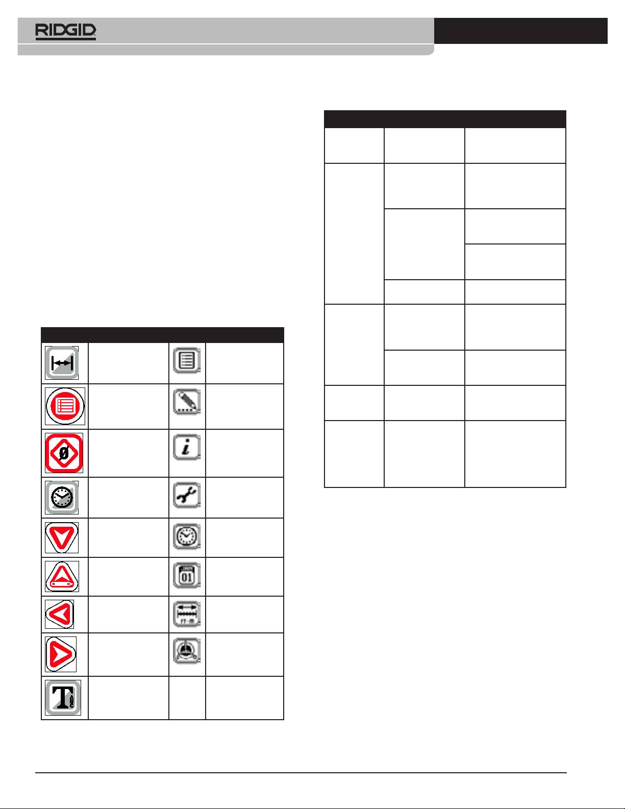
Icons and Symbols
Count accuracy
Settings incorrect for
Verify the settings are correct
seems
reel or cable being
for the SeeSnake cable
Key Pad Menus
unreliable.
used.
length, cable diameter and
reel type you are using.
Measurement Display
Counting from a zero
Conrm you are measuring
Menu Icon
On/Off
point other than the
from the intended zero-point.
one intended.
Low Battery
Battery dead or near-
Replace 3-volt battery in the
warning
dead.
CountPlus (CR2450).
Menu Key Slide Edit Screen
appears.
The symbol “+”
Physical cable meas-
Verify the actual length of
appears after
urement has exceeded
your installed cable; re-set
the on-screen
the cable parameter in
the reel and cable settings
Zero/Select Key Information Screen
distance
settings.
for the correct reel type and
measurement.
actual cable length and diam-
eter as described on page 5.
Time/Date Display
Tools Menu
On/Off
Down Arrow Time Settings
Up Arrow/Edit Key Date Settings
Measurement Unit
Left Arrow
Settings
Reel and Cable
Right Arrow
Settings
Text Key
Figure 19: Icons and Symbols
744_031-601_0A_RevA_Countplus_ma10 10 9/04/2009 10:28:24
Ridge Tool Company
11
Tools For The Professional
TM
®
SEESNAKE
COUNTPLUS METERZÄHLER
Allgemeine Sicherheitshinweise
D
WARNUNG
®
SeeSnake
CountPlus Meterzähler
Bitte lesen Sie diese Anweisungen sorgfältig durch. Die Nichtbeachtung
Bedienungsanleitung
der nachfolgenden Anweisungen kann zu Stromschlag, Brand und/oder
schweren Verletzungen führen.
WARNUNG! Lesen Sie diese Bedie-
Sicherheit im Arbeitsbereich
nungsanleitung vor dem Gebrauch des
• Halten Sie Ihren Arbeitsbereich sauber, und sorgen Sie für eine gute
Geräts sorgfältig durch. Die Unkennt-
Beleuchtung. Unaufgeräumte Werkbänke und schlecht beleuchtete
nis und Nichtbeachtung des Inhalts
Arbeitsbereiche erhöhen das Unfallrisiko.
• Betreiben Sie elektrische Geräte oder Elektrowerkzeuge nicht in
dieser Bedienungsanleitung kann zu Stromschlag,
Umgebungen mit erhöhter Explosionsgefahr, in denen sich leicht
Brand und/oder schweren Verletzungen führen.
entammbare Flüssigkeiten, Gase oder Staub benden. Elektrische
Geräte oder Elektrowerkzeuge erzeugen im Betrieb Funken, durch die
Sicherheitssymbole
sich Staub oder leicht entammbare Dämpfe entzünden können.
• Sorgen Sie beim Betrieb elektrischer Werkzeuge dafür, dass sich
Wichtige Sicherheitshinweise werden in dieser Bedienungsanleitung mit
keine Kinder, sonstige Unbeteiligte oder Besucher in der Nähe
bestimmten Sicherheitssymbolen und Warnungen gekennzeichnet. Dieser
benden. Bei Ablenkungen kann die Kontrolle über das Werkzeug
Abschnitt enthält Erläuterungen zu diesen Warnhinweisen und Symbolen.
verloren gehen.
Elektrische Sicherheit
Dies ist das allgemeine Gefahren-Symbol. Es weist auf mögliche
• Das System darf keinesfalls mit offenliegenden elektrischen
Verletzungsgefahren hin. Beachten Sie alle Hinweise mit diesem
Komponenten betrieben werden. Freiliegende interne Bauteile erhöhen
Symbol, um Verletzungs- oder Lebensgefahr zu vermeiden.
die Verletzungsgefahr.
• Halten Sie Geräte von Regen und Nässe fern. Batterie nicht mit
GEFAHR weist auf eine gefährliche Situation hin, die
Wasser in Berührung bringen. Das Eindringen von Wasser in ein
ohne entsprechende Sicherheitsvorkehrungen zugen zu
Elektrogerät erhöht die Stromschlaggefahr.
Lebensgefahr oder schweren Verletzungen führt.t.
GEFAHR
• Das Gerät darf nicht in Rohrleitungen eingesetzt werden, in denen
Hochspannungsleitungen liegen.
WARNUNG weist auf eine gefährliche Situation hin,
die ohne entsprechende Sicherheitsvorkehrungen zu
Lebensgefahr oder schweren Verletzungen führen
Sicherheitshinweise zur Batterie
• Verwenden Sie ausschließlich Batterien des angegebenen Typs
WARNUNG
kann.
in passender Größe. Andernfalls kann die Elektronik beschädigt
ACHTUNG weist auf eine gefährliche Situation hin,
werden.
die ohne entsprechende Sicherheitsvorkehrungen
• Batterien sind fachgerecht zu entsorgen. Bei großer Hitze kann
zu kleineren bis mittelschweren Verletzungen führen
die Batterie explodieren, sie darf daher nicht verbrannt werden. In
ACHTUNG
kann.
manchen Ländern gelten besondere Vorschriften für die Entsorgung von
HINWEIS
HINWEIS kennzeichnet Informationen, die sich auf die
Altbatterien. Beachten Sie die örtlich geltenden Bestimmungen.
Vermeidung von Sachschäden beziehen.
Sicherheit von Personen
Dieses Symbol weist auf die Gefahr hin, dass Hände,
• Seien Sie beim Betrieb eines elektrischen Geräts immer aufmerk-
Finger oder andere Körperteile sich verfangen
sam und verantwortungsbewusst. Verwenden Sie Diagnosegeräte
können.
nicht unter Einuss von Drogen, Alkohol oder Medikamenten. Durch
einen kurzen Moment der Unaufmerksamkeit bei der Arbeit mit
Diagnosegeräten können Sie sich selbst oder anderen erhebliche
Dieses Symbol weist auf die Gefahr von Stromschlägen
Verletzungen zufügen.
hin.
• Aus Gründen des Gesundheitsschutzes und der Sicherheit sind
stets Handschuhe zu tragen. Abwasserleitungen sind unhygienisch und
Dieses Symbol weist auf die Gefahr hin, dass Hände,
können gesundheitsgefährdende Bakterien und Viren enthalten.
Finger oder andere Körperteile gequetscht werden
• Überschätzen Sie sich nicht. Sorgen Sie stets für sicheren Halt
können.
und einen festen Stand. Durch sicheren Halt und gutes Gleichgewicht
können Sie das Gerät in unerwarteten Situationen besser kontrollieren.
744_031-601_0A_RevA_Countplus_ma11 11 9/04/2009 10:37:15
12
Ridge Tool Company
Tools For The Professional
TM
®
SEESNAKE
COUNTPLUS METERZÄHLER
• Tragen Sie Schutzkleidung. Tragen Sie IMMER einen Augenschutz.
Technische Daten
Je nach Umgebung sind Staubmaske, rutschfeste Sicherheitsschuhe,
• Gewicht ohne Batterie 100 g
Schutzhelm oder Gehörschutz erforderlich.
• Gewicht mit Batterie 105 g
• Schützen Sie das Gerät vor dem Eindringen von Schmutz und
Abmessungen
Flüssigkeit. Schütten Sie niemals Flüssigkeit auf den CountPlus.
• Breite 8,5 cm
Flüssigkeit erhöht die Stromschlaggefahr und kann zu Schäden am
• Höhe 7,3 cm
Gerät führen.
• Tiefe 4 cm
• Arbeiten Sie nicht bei starkem Verkehr. Achten Sie bei Einsätzen
auf oder neben Straßen auf vorbeifahrende Fahrzeuge. Tragen
Stromversorgung
Sie Warnbekleidung oder mindestens eine Warnweste. Mit diesen
• 1 x CR2450 3 V Knopfzelle
Vorsichtsmaßnahmen schützen Sie sich vor schweren Verletzungen.
Umgebungsbedingungen
• Temperatur -20 °C bis 50 °C
CountPlus Betrieb und Pege
• Luftfeuchtigkeit 5 % - 95 % RF
• Das Gerät darf nur bestimmungsgemäß verwendet werden.
• Aufbewahrung -20 °C bis 60 °C
Beginnen Sie erst mit der Arbeit, wenn Sie die Bedienungsanleitung zu
SeeSnake gelesen haben und eine Schulung zur Bedienung des Gerätes
Standardausstattung
erhalten haben.
Artikel Best.-Nr. #
• Tauchen Sie den CountPlus niemals in Wasser. Lagern Sie das
• CountPlus 31753
Gerät an einem trockenen Ort. Dadurch verringert sich die Gefahr von
Stromschlag und Beschädigungen.
• Bewahren Sie unbenutzte Elektrowerkzeuge außerhalb der
BEWAHREN SIE DIESE ANLEITUNG AUF!
Reichweite von Kindern und unerfahrenen Personen auf. Geräte sind
gefährlich, wenn Sie von unerfahrenen Personen benutzt werden.
Die mitgelieferten Bedienungsanleitungen müssen am Gerät mitgeführt
• Behandeln Sie das Gerät mit Sorgfalt.
werden und sind dem Bediener des Geräts zugänglich zu machen.
• Überprüfen Sie, dass keine Teile gebrochen sind oder sonstige
Fehler vorliegen, um den reibungslosen Betrieb von SeeSnake und
CountPlus
sicherzustellen. Bei Beschädigungen muss das Gerät vor
CountPlus Einbau
einer erneuten Verwendung zunächst repariert werden. Viele Unfälle
Nachrüsten eines CountPlus an einer vorhandenen SeeSnake erfordert den
werden durch schlecht gewartete Geräte verursacht.
Einbau des Geräts. Anhang A enthält eine ausführliche Einbauanleitung.
• Vor starker Hitze schützen. Das Gerät nicht in der Nähe von
Wärmequellen wie Heizungen, Wärmezählern, Herden oder sonstigen
Kontrolle des Geräts
Geräten (einschließlich Verstärkern) die Wärme erzeugen, betreiben.
WARNUNG
Wartung
Der CountPlus darf nur von qualiziertem Fachpersonal gewartet werden, um
den sicheren Betrieb des Geräts sicherzustellen.
Beschreibung, technische Daten
und Standardausstattung
Der CountPlus ist ein weiterentwickeltes Gerät zur digitalen
SeeSnake und CountPlus sind vor Gebrauch gründlich zu
Entfernungsmessung und zum Einblenden von Text, das auf jede SeeSnake-
kontrollieren, um die Verletzungsgefahr durch Stromschlag oder
®
Trommel
mit Standard- oder Minikamera montiert werden kann. Der
andere Verletzungen zu vermeiden.
CountPlus ist auf der geschlossenen Seite der Trommel unterhalb der Achse
eingebaut. Der Entfernungsmesser misst Entfernungen auf Grundlage der
1. SeeSnake vom Monitor trennen und Verbindungskabel und Stecker
Trommeldrehung beim Einschieben der Kamera in eine Rohrleitung. Es
/ Kupplung auf Beschädigungen oder Veränderungen untersuchen.
ersetzt das bisherige Entfernungsmessgerät CountIR.
Werden Beschädigungen oder Veränderungen festgestellt, muss
das Gerät erst repariert oder ausgetauscht werden, bevor es weiter
Der CountPlus verfügt über ein Spritzwasser geschützt Tastenfeld mit 9 Tasten
verwendet wird.
zum Einstellen der Bildschirmanzeigen. Bei Videoaufnahmen werden auch
2. Die SeeSnake von Öl- und Fettrückständen sorgfältig säubern, insbeson-
alle auf dem Bildschirm dargestellten Anzeigen mit aufgezeichnet.
dere das Gestell reinigen, damit es beim Tragen oder Aufstellen nicht aus
der Hand rutscht.
Eingeblendete Funktionen / Daten
3. SeeSnake auf Schäden oder Veränderungen prüfen sowie auf defekte,
verschlissene, fehlende, falsch ausgerichtete bzw. festhängende Teile
Entfernung Entfernung, die die Kamera insgesamt oder ab einem
oder sonstige Fehler, die einen sicheren Betrieb gefährden. Die Trommel
ausgewählten Punkt in der Leitung zurückgelegt hat.
muss frei drehen und die Reibungssperre der Trommel störungsfrei
Texteinblendung Zur Eingabe von Titeln und Beschreibungen von
arbeiten. Prüfen Sie das Kabel auf Anzeichen von Rissen oder erhöhtem
Abschnitten des aufgenommenen Videos.
Verschleiß. Prüfen Sie die Verbindungen am Kamerakopf auf Dichtigkeit.
Uhrzeit und Datum Ein- und Ausblenden von Datum und/oder
Falls Probleme auftreten, müssen diese vor dem Einsatz der SeeSnake
Uhrzeit.
beseitigt sein.
744_031-601_0A_RevA_Countplus_ma12 12 9/04/2009 10:37:18
Ridge Tool Company
13
Tools For The Professional
TM
®
SEESNAKE
COUNTPLUS METERZÄHLER
Vorbereiten von Gerät und Arbeitsbereich
CountPlusTasten
WARNUNG
Taste Pfeil nach oben / Bearbeiten
Pfeil nach rechts
Texteingabetaste
Taste Hauptmenü / zurück
Bereiten Sie die SeeSnake und den Arbeitsbereich vor, um Verlet-
Taste Null / Auswahl
zungsgefahr durch Stromschlag, Feuer, Quetschen und andere Ursa-
chen sowie Schäden am Gerät zu verringern.
Pfeil nach links
1. Prüfen Sie den Arbeitsbereich auf ausreichende Beleuchtung.
2. Der Arbeitsbereich muss tragfähig und eben sein, um die SeeSnake zum
Arbeiten sicher aufstellen zu können.
3. Betreiben Sie die SeeSnake nicht in Umgebungen mit erhöhter
Taste für
Explosionsgefahr, in denen sich leicht entammbare Flüssigkeiten,
Entfernungsmessung
entammbare Dämpfe oder Staub benden.
4. Für den Bediener muss eine ausreichend freie, trockene und ebene
Fläche vorhanden sein, um mit dem Schubkabel ungehindert arbeiten zu
Pfeil nach unten
können.
5. Es muss eine frei zugängliche Steckdose vorhanden sein, in die das
Stromversorgungskabel gefahrlos eingesteckt werden kann.
6. Verlängerungskabel nur verwenden, wenn unbedingt erforderlich.
Es dürfen nur Kabel für den Einsatz im Freien mit ausreichendem
Taste für Zeiteinstellung
Querschnitt verwendet werden.
Abbildung 1: CountPlus Tastenfeld
Mindestquerschnitt von Verlängerungskabeln
Beschreibung des Tastenfelds
In Abbildung 1 sind die Bezeichnungen der Tasten dargestellt. Sie haben
Ampere
folgende Funktionen:
gemäß
Gesamtkabellänge (Fuß)
Texteingabetaste
Blendet den Texteingabebildschirm ein oder aus.
Typenschild
Menütaste / zurück Öffnet das Hauptmenü.
0 - 25 26 - 50 51 - 100
Entfernungstaste Blendet Entfernungsangaben ein oder aus.
0 - 6 18 AWG 16 AWG 16 AWG
Taste für Zeiteinstellung Schaltet um zwischen der Anzeige von
6 - 10 18 AWG 16 AWG 16 AWG
Datum, Zeit, Datum und Zeit oder keiner Anzeige.
10 - 12 16 AWG 16 AWG 14 AWG
Pfeiltasten nach links und nach rechts
Mit diesen
12 - 16 14 AWG 12 AWG NICHT VERWENDEN
Tasten kann durch die vorhandenen Slides zu neuen Slides navigiert
werden, wenn Text eingeblendet ist.
Dienen zum Navigieren durch die Menüauswahl und die Zeichen.
Pfeiltaste nach oben / Bearbeiten
Mit dieser Pfeiltaste kann
direkt zur Bearbeitungsseite für vorhandene Slides gewechselt werden,
wenn beim Drücken der Taste Text im Slide eingeblendet wird. Dient zum
Navigieren durch die Menüauswahl oder die Zeichen.
Pfeiltaste nach unten
Dient im Bearbeitungsmodus zum
Navigieren durch Menüauswahl, Werte und Zeichen.
Taste Null / Auswahl
Dient zur Auswahl eines markierten
Menüpunkts. Startet den lokalen Nullpunkt-Entfernungsmesser. Taste
mindestens 3 Sekunden gedrückt halten, um den Entfernungsmesser auf
null zurückzusetzen.
744_031-601_0A_RevA_Countplus_ma13 13 9/04/2009 10:37:22
14
Ridge Tool Company
Tools For The Professional
TM
®
SEESNAKE
COUNTPLUS METERZÄHLER
Systemeinstellungen
Drücken der Menütaste führt zur Einblendung des Hauptmenüs mit
seinen drei Symbolen.
Abbildung 4: Informationsbildschirm
Menü Einstellungen - Mit diesem Symbol aktivieren Sie das
Menü zum Einstellen von Systemdatum und -zeit, Trommelgröße und
Abbildung 2: Hauptmenü
Schubkabellänge sowie der verwendeten Einheiten.
Textbearbeitung - Mit dieser Option kann direkt in das Menü zum
Bearbeiten von Slides gewechselt werden, in dem ein vorhandenes Slide
Um eines der Symbole auszuwählen, die Pfeiltasten
zur Bearbeitung ausgewählt werden kann. Eine ausführliche Anleitung zum
drücken, und eines der ausgewählten Symbole markieren. Taste Null / drücken, und eines der ausgewählten Symbole markieren. Taste Null /
Bearbeiten von Titeln und Texten in Slides ist auf Seite 8 zu nden.
Auswahl drücken um Auswahl zu aktivieren.
Abbildung 3: Bearbeitungsbildschirm
Abbildung 5: Menü Einstellungen
Informationsbildschirm - Mit diesem Symbol aktivieren Sie ei-
Systemzeit
nen Informationsbildschirm mit der Anzeige der installierten Softwareversion
des CountPlus, dem kongurierten Videotyp (NTSC oder PAL) und der seit
Mit den Pfeiltasten zum Werkzeugsymbol zum Werkzeugsymbol
Programmierung des Geräts zurückgelegten Gesamtstrecke.
navigieren
und anschließend die Taste Null / Auswahl drücken . Im
Untermenü das Uhrensymbol markieren und die Taste Null / Auswahl
erneut drücken. Es erscheint ein Menü mit dem Zeitformat, den
Werten für Stunde, Minute und Sekunde und der Auswahl AM/PM. Mit den
Pfeiltasten zum gewünschten Menüpunkt navigieren und mit den Pfeiltasten
nach oben und nach unten
die gewünschten Einstellungen
vornehmen.
744_031-601_0A_RevA_Countplus_ma14 14 9/04/2009 10:37:30
Ridge Tool Company
15
Tools For The Professional
TM
®
SEESNAKE
COUNTPLUS METERZÄHLER
mit dem jeweils eingesetzten SeeSnake-System sicherzustellen. Bei der
Einrichtung des CountPlus muss es entsprechend der Trommelgröße und
dem Schubkabeltyp des SeeSnake-Systems konguriert werden (Mini oder
Standard).
1. Werkzeugmenü auswählen .
2. Trommelsymbol auswählen
3. Mit den Pfeiltasten nach oben und nach unten zwischen den drei
Parametern navigieren und mit den Pfeiltasten nach rechts und links die
entsprechenden Werte einstellen.
Abbildung 6: Systemzeit-Anzeige
Format wählbar als 12-Stunden- oder 24-Stunden-Anzeige. Menütaste
drücken
, um Auswahl zu bestätigen und das Menü zu verlassen. Wenn
keine Eingaben erfolgen, wird das Menü über einen Timer nach
10 Sekunden automatisch geschlossen.
Systemdatum
Das Werkzeugmenü öffnen und zum Kalendersymbol navigieren
Abbildung 8: Einstellungen für Trommel und Schubkabel
, mit dem die Kalendereinstellungen vorgenommen werden können.
In der Anzeige erscheint eine Auswahl für das Kalenderformat und zur
4. Mit der Pfeiltaste in die erste Zeile navigieren (Schubkabellänge) und
Datumseingabe.
durch Drücken der linken oder rechten Pfeiltaste den Entfernungsmesser
schrittweise auf die korrekte Länge in Fuß einstellen. Bei länger gedrück-
Als Datumsformat für die Datumsanzeige stehen Monat/Tag/Jahr (MM/DD/
ter Pfeiltaste läuft die Anzeige schneller durch. Nachfolgende Tabelle
YYYY) oder Tag/Monat/Jahr (DD/MM/YYYY) zur Auswahl. Mit den Pfeiltasten
enthält die Standardlängen für SeeSnake Mini und Standard.
die Eingabefelder für Monat oder Tag markieren und mit den Pfeiltasten
nach oben oder nach unten
zwischen den beiden Formate zwischen den beiden Formate
Sollte das Schubkabel eine andere als die angegebenen Längen
auswählen. Mit den Pfeiltasten die jeweilige Ziffer im Eingabefeld markieren
aufweisen, dann kann diese bis auf 5 Fuß genau eingestellt werden.
und mit den Pfeiltasten nach oben und nach unten
das Datum das Datum
Tabelle 1: Abmessungen Standardkabel
einstellen. Menütaste drücken,
um Auswahl zu bestätigen und das
MINI Standard
Menü zu verlassen.
Kabeldurch-
0.36” 0.44”
messer
9,144 mm 11,176 mm
Kabellänge 100’ 100’
30 m 60 m
5. Mit der Pfeiltaste nach unten in die zweite Zeile navigieren und für das
verwendete Gerät die entsprechende Trommelgröße für Mini, Compact
oder Standard eingeben. Wenn nicht genau klar ist, welche Trommel
verwendet wird, kann mit folgender Messung herausgefunden werden,
um welche Trommel es sich handelt:
Tabelle 2: Abmessungen Trommeln
MINI Standard
Abbildung 7: Systemdatum-Anzeige
Innenradius
8.25” 11.82”
der Trommeln
209,5 mm 300,2 mm
Einstellungen für Trommel und Schubkabel
Trommelbreite 5” 6.76”
Das Einstellen der korrekten Trommelgröße und des Schubkabeltyps
gehört zu den Grundeinstellungen des CountPlus, um korrekte Messungen
127 mm 171,7 mm
744_031-601_0A_RevA_Countplus_ma15 15 9/04/2009 10:37:38
16
Ridge Tool Company
Tools For The Professional
TM
®
SEESNAKE
COUNTPLUS METERZÄHLER
6. Mit der Pfeiltaste nach unten in die dritte Zeile navigieren (Einstellung
bestimmter Szenen oder Abschnitte der Videoaufnahme verwendet werden.
für das Schubkabel). Mit Hilfe der Tabelle 1 kann der Schubkabeltyp des
Wird ein Slide auf dem Bildschirm eingeblendet, erscheint der Text dieses
vorhandenen Systems festgestellt werden.
Slides in den aufgezeichneten Rahmen.
7. Die Einstellung für den Schubkabeltyp entsprechend des in der
Der Bediener kann zwischen verschiedenen Möglichkeiten wählen, die
SeeSnake vorhandenen Kabels vornehmen. Menütaste drücken ,
Slides in einer Aufzeichnung einzublenden.
um Auswahl zu bestätigen und das Menü zu verlassen.
1. Ein neues Slide für eine Einblendung anlegen.
2. Ein vorhandenes Slide bearbeiten.
Diese Grundeinstellungen müssen nur einmal bei Inbetriebnahme des
3. Ein vorhandenes Slide für die Einblendung auswählen.
Geräts eingegeben werden, es sei denn, es ändern sich bestimmte
4. Slide-Einblendung ein- oder ausschalten.
Einstellungen. Wenn die Angabe der Schubkabellänge auf dem Bildschirm
Ein neues Slide anlegen.
die voreingestellte Länge überschreitet, ist dem Messwert das Symbol +
Ein neues Slide zum Einblenden anlegen:
vorangestellt.
1) Durch Drücken der Texteingabetaste in den Texteingabebildschirm wech-
Einheiten
seln
und die Taste nach unten drücken . Es erscheint eine Liste
Der CountPlus kann so eingestellt werden, dass er Entfernungen in Fuß,
der vorhandenen Slides mit dem Eintrag “New Slide” ganz unten. Mit der
Inches oder Metern angibt. Die jeweiligen Einheiten können in verschie-
Pfeiltaste nach unten navigieren bis “New Slide” blinkt und anschließend
denen Formaten ausgegeben werden.
die Taste Null / Auswahl drücken
Fuß Meter
XX’ YY” X.xx m
XX ft YY in X.x m
XX.x ft
Einstellen der gewünschten Einheit und des gewünschten Formats:
1. Menütaste drücken Werkzeugmenü auswählen und an-
schließend
Einheitenmenü.
2. Mit der Pfeiltaste zur linken Spalte navigieren und mit der Pfeiltaste nach
oben Fuß oder Meter auswählen.
Mit der Pfeiltaste zur rechten Spalte navigieren und mit den
Pfeiltasten nach oben und nach unten
eines der
Abbildung 10: Menüpunkt “New Slide” auswählen.
verfügbaren Formate auswählen. Menütaste drücken,
um Auswahl zu
2) Es erscheint ein neues Slide im Bearbeitungsmodus. Der Cursor bendet
bestätigen und das Menü zu verlassen.
sich Im Bereich des Slide-Titels. Mit den Pfeiltasten nach rechts und
nach links kann zwischen den Zeichen des Titels navigiert werden
. Der Slide-Titel kann durch Auswahl der Zeichen erstellt werden
(siehe Schritt 4 weiter unten).
Abbildung 9: Bildschirmanzeige der Einheiten
Die Einstellungen für Trommelgröße, Schubkabellänge und gemessene
Entfernung werden auf dem Bildschirm mit den eingestellten Einheiten
Abbildung 11: Neues Slide
eingeblendet.
3) Pfeiltaste nach unten drücken , um die Titelzeile zu verlassen und
Einstellungen für Text-Slides
in den Textbereich zu wechseln. Den Cursor mit den Pfeiltasten an die
Der CountPlus bietet die Möglichkeit, in 20 verschiedenen Slides Titel und
Stelle navigieren, an der der Text eingeblendet werden soll.
bis zu 6 Zeilen Text einzublenden. Diese Slides können zur Kennzeichnung
744_031-601_0A_RevA_Countplus_ma16 16 9/04/2009 10:37:47
Ridge Tool Company
17
Tools For The Professional
TM
®
SEESNAKE
COUNTPLUS METERZÄHLER
Hinweis: Wird kein Slide-Titel eingegeben, verwendet der CountPlus
c. Durch Drücken der Menütaste wird das Slide gespeichert , das auf
die ersten 10 Zeichen des im Textbereich eingegebenen Textes als Titel.
dem Layout-Bildschirm angezeigt wird.
Dies geschieht nur, wenn der Bereich des Slide-Titels leer bleibt.
d. Das Slide wird beim Verlassen des Slides automatisch gespeichert,
vorausgesetzt es wurde ein Text eingegeben.
Ein vorhandenes Slide bearbeiten.
1) Die Texteingabetaste drücken , um den Text des aktuellen Slides
anzuzeigen.
2) Mit den Pfeiltasten nach links und nach rechts durch die Slides
navigieren bis dasjenige erscheint, das bearbeitet werden soll. Alternativ
kann auch die Pfeiltaste nach unten gedrückt werden
, um durch
eine Liste mit Titeln zu navigieren und durch Drücken der Taste Null /
Auswahl den gewünschten markierten Titel auszuwählen.
3) Die Taste nach oben / Bearbeiten drücken , um in den
Bearbeitungsmodus des aktuell angezeigten Slides zu wechseln.
4) Nach Abschluss der gewünschten Änderungen die Menütaste drücken
, um den Bearbeitungsmodus zu verlassen.
Abbildung 12: Slide-Textbereich
Ein Slide zum Einblenden auswählen.
4) Im Bearbeitungsmodus wird mit der Texteingabetaste zwischen
1) Die Texteingabetaste drücken , um den Text des aktuellen Slides
Slide-Layout und Textauswahlbildschirm umgeschaltet.
anzuzeigen, falls dieser noch nicht angezeigt wird.
a. Im Layout-Bildschirm kann mit Hilfe der Pfeiltasten auf dem Bildschirm
dorthin navigiert werden, wo die Zeichen eingeblendet werden sollen.
2) Mit den Pfeiltasten nach links und nach rechts durch die
Wenn der Cursor an der gewünschten Stelle auf dem Bildschirm steht,
Slides navigieren bis dasjenige erscheint, dass eingeblendet werden
die Texteingabetaste drücken
, um in den Textauswahlbildschirm
soll. Mit den Pfeiltasten nach links oder nach rechts
wird
zu wechseln und an der vorgesehenen Stelle mit den entsprechenden
zwischen den eingeblendeten Slides nach vorne oder zurück navigiert.
Zeichen den Text einzugeben.
3) Wird eine Leitungsdiagnose aufgezeichnet und soll während der
Aufzeichnung das eingeblendete Slide verändert werden, die Aufnahme
5) Im Textauswahlbildschirm kann mit Hilfe der Pfeiltasten zwischen den
anhalten, bis das gewünschte Slide ausgewählt ist. Anschließend können
Zeichen, Zahlen, Symbolen oder Rückwärts navigiert werden. Wenn das
Diagnose und Aufzeichnung fortgesetzt werden. Das eingeblendete Slide
gewünschte Zeichen markiert ist, die Taste Null / Auswahl drücken
,
wird zusammen mit der Videoaufnahme durch die Kamera aufge-
um es in das Slide einzufügen. Diesen Vorgang für alle Zeichen solange
zeichnet. Wenn beispielsweise an einer Stelle, an der Wurzeln ins Bild
wiederholen, bis der gewünschte Slide-Text fertiggestellt ist. Hinweis:
kommen, eine Einblendung mit dem Hinweis “Wurzeln” erfolgen soll.
Das Rückwärts-Symbol () dient als Löschtaste.
Slide-Einblendung ein- oder ausschalten.
1) Texteingabetaste drücken , um das Slide ein- oder auszublenden.
Ein Slide löschen
Ein Text-Slide löschen:
1. Mit der Texteingabetaste in den Texteingabebildschirm wechseln ,
Papierkorb
die Pfeiltaste nach unten drücken
; eine Liste der vorhandenen
Slides erscheint.
2. Mit der Pfeiltaste nach unten das zu löschende Bild auswählen und die
Taste Null / Auswahl drücken.
3.
Im Textbereich den Cursor mit den Pfeiltasten bis unter das Papierkorb-
Symbol navigieren
. In Abbildung 13 bendet sich der Papierkorb
rechts neben der Titelzeile. Mit der Pfeiltaste nach oben navigieren
bis das Papierkorb-Symbol
blinkt und anschließend die Taste Null /
Abbildung 13: Textauswahlbildschirm
Auswahl drücken. (Alternativ kann auch das Papierkorb-Symbol am Ende
des dargestellten Zeichensatzes angewählt werden - siehe Abbildung 13.)
a. Soll ein anderer Bereich im Slide angesteuert werden, kann durch
4. Es erscheint ein Bildschirm mit Bestätigungsaufforderung. Zum Löschen
Drücken der Texteingabetaste in den Layout-Bildschirm zurückgewech-
des Slides markieren Sie das Kontrollkästchen und drücken Sie die Taste
selt werden
.
Null / Auswahl. Zum Abbrechen des Löschvorgangs markieren Sie das
b. Zum Bearbeiten des Slide-Titels kann mit den Pfeiltasten in die Titelzeile
Symbol
X und drücken Sie die Taste Null / Auswahl oder einfach die
navigiert werden. Der vorhandene Text kann nun durch eigene Eingaben
Menütaste.
ersetzt werden.
744_031-601_0A_RevA_Countplus_ma17 17 9/04/2009 10:38:00
18
Ridge Tool Company
Tools For The Professional
TM
®
SEESNAKE
COUNTPLUS METERZÄHLER
Zurücksetzen des System-Nullpunkts Der System-Nullpunkt kann
jederzeit durch längeres Drücken (länger als 3 Sekunden) der Taste Null /
Auswahl zurückgesetzt werden. Diese Vorgehensweise eignet sich vor allem
zu Beginn einer Diagnose am Zugang zu einer Leitung.
Lokaler Nullpunkt Während des Betriebs kann der CountPlus auch so
eingestellt werden, dass er mit einem zweiten Entfernungsmesser von einem
beliebigen “lokalen Nullpunkt” aus die Entfernung misst.
1) Um die Entfernung ab einem beliebigen Punkt zu messen, z.B. ab einer
Abzweigstelle in einer Rohrleitung, die Taste Null / Auswahl kurz
drücken. Die eingeblendete Entfernung wird auf null [0.0] gesetzt. Die
rechteckigen Klammern zeigen an, dass die Messung ab einem lokalen
Nullpunkt und nicht ab dem System-Nullpunkt beginnt.
a) Taste Null / Auswahl drücken , um die Einblendung zwischen
bisherigem und neuem Nullpunkt [0.0] umzuschalten.
Abbildung 14: Löschen bestätigen
b) Wenn mit der Messung der Kabellänge ab einem lokalen Nullpunkt
begonnen wird, darf die Taste Null / Auswahl bis zum Ende der
laufenden Messung nicht erneut gedrückt werden, da sonst der lokale
CountPlus Bedienungsanleitung
Nullpunkt auf null zurückgesetzt wird und die bisherige Messung
Grundfunktion
verloren geht.
SeeSnake an die Stromversorgung anschließen, einschalten und mit den
Tasten für Entfernung
und Zeit die gewünschten Daten einstellen,
die eingeblendet werden sollen.
a) Die Taste für Zeiteinstellung schaltet um zwischen der Anzeige von
Datum, Datum und Zeit, Zeit oder keiner Anzeige. Die Taste für jeden
Schritt durch die Auswahl einmal drücken.
b) Die Taste für Entfernungsmessung blendet die Entfernungsangaben auf
dem Bildschirm ein oder aus.
c) Der Entfernungsmesser zeigt die Entfernung in den Einheiten an, die
im Menü Einstellungen /Einheiten voreingestellt sind (siehe
Einheiten weiter oben).
Abbildung 16: Messung ab eingestelltem lokalem Nullpunkt
c) Vorsichtshalber kann der Ausgangsmesswert des Systems notiert
werden, der kurz vor dem Einstellen des neuen Nullpunkts erreicht
wurde. (Damit ergibt sich die Möglichkeit, die Entfernung mit dem
System-Messwert auszurechnen, falls der lokale Nullpunkt aus
Versehen gelöscht wurde).
2) Der CountPlus misst weiterhin die Entfernung, die das Schubkabel zu-
rücklegt und blendet den Gesamtwert ein (wenn die Entfernungsangabe
eingestellt ist), beginnend ab dem System-Nullpunkt oder dem aktuellen
lokalen Nullpunkt, wenn eines von beiden voreingestellt wurde.
3) Zurücksetzen des System-Nullpunkts Der System-Nullpunkt kann
jederzeit durch längeres Drücken (länger als 3 Sekunden) der Taste Null
Abbildung 15: Bildschirmeinblendung mit Slide-Text, Zeit und Entfernung
/ Auswahl zurückgesetzt werden. Alle folgenden Entfernungsmessungen
(Entfernung gemessen ab System-Nullpunkt)
des Systems beginnen bis zum Abschalten bei diesem neuen
System-Nullpunkt. Dabei wird dann auch der lokale System-Nullpunkt
zurückgesetzt.
System-Nullpunkt und lokaler Nullpunkt
Der in Abbildung 15 eingeblendete Entfernungsmesser startet beim
Einschalten des Systems bei null. Dies ist der sogenannte “System-
Wie der CountPlus Entfernungen
Nullpunkt”. Der physische Ausgangspunkt, an dem das System seine
misst
Messung beginnt, kann durch Ausschalten des Systems, Ein- oder
Der CountPlus nutzt zur Messung zwei Magneten in der Trägerplatte des
Ausfahren des Schubkabels bis zum gewünschten Nullpunkt und durch
CountPlus Geräts. Durch die Drehung der Trommel wechseln die Magneten
Wiedereinschalten des Systems an dieser Stelle verändert werden. Der
die Polrichtung relativ zum CountPlus und dieser Wechsel wird von Hall-
Entfernungsmesser beginnt beim erneuten Einschalten des Systems wieder
Effekt-Sensoren des CountPlus erfasst. Ein eingebauter Computer nutzt die
bei null.
Sensorsignale und berechnet unter Berücksichtigung von Trommelgröße
744_031-601_0A_RevA_Countplus_ma18 18 9/04/2009 10:38:04
