Partner B305 CBS Rev.7: instruction
Class: Gardening equipment
Type:
Manual for Partner B305 CBS Rev.7

B305 CBS
INSTRUCTION MANUAL
IMPORTANT INFORMATION
: Please read these instructions carefully and make
GB
sure you understand them before using this unit. Retain these instructions for future
reference.
ИНСТРУКЦИЯ ПО ЭКСПЛУАТАЦИИ
ВАЖНАЯ ИНФОРМАЦИЯ:
Пожалуйста, внимательно прочтите данную
RU
инструкцию перед тем, как приступить к зксппуатации триммера, и убедитесь что
она вам понятна. Сохраните инструкцию для дальнейшего обращения к ней.
ANVÄNDARHANDBOK
VIKTIG INFORMATION
: Läs dessa anvisningar noggrant och se till att du förstår
SE
dem innan du använder trimmeren och spara dem för framtida behov.
BRUKERHÅNDBOK
NO
VIKTIG INFORMASJON:
Vennligst les disse instruksjonene nøye og pass på at De
forstår dem før De bruker trimmeren og oppbevar den for senere bruk.
BRUGERHÅNDBOG
VIGTIGE OPLYSNINGER:
Læs venligst disse instruktioner omhyggeligt og vær
DK
sikker på, at De forstår dem, før De anvender græstrimmeren og gemme til senere
henvisning.
KÄYTTÖOHJEKIRJA
FI
TÄRKEÄÄ:
Lue tämä ohjekirja huolellisesti läpi ennen kuin alat käyttää laitetta.
Säilytä ohjekirja myöhempää käyttöä varten.
INSTRUKCJA OBSŁUGI
WAZNE INFORMACJE:
Przed rozpoczęciem użytkowania urządzenia, należy
PL
uważnie przeczytać i zrozumieć ninijszą instrukcją. Instrukcje należy przechowywać
do późniejszego z niej korzystania.
NÁVOD K POUŽĺVÁNĺ
CS
DŮLEŽITÁ INFORMACE:
Prosíme, než začnete zařízení používat, přečtěte si
pečlivě tyto pokyny a ujistěte se, že jim plně rozumíte.
ПОСІБНИК З ЕКСПЛУАТАЦІЇ
ВАЖЛИВА ІНФОРМАЦІЯ.
Уважно прочитайте інструкції та переконайтеся, що
UA
Ви їх зрозуміли, перш ніж використовувати пристрій. Зберігайте ці інструкції для
подальшого використання.
576191709 Rev. 7 07/22/14

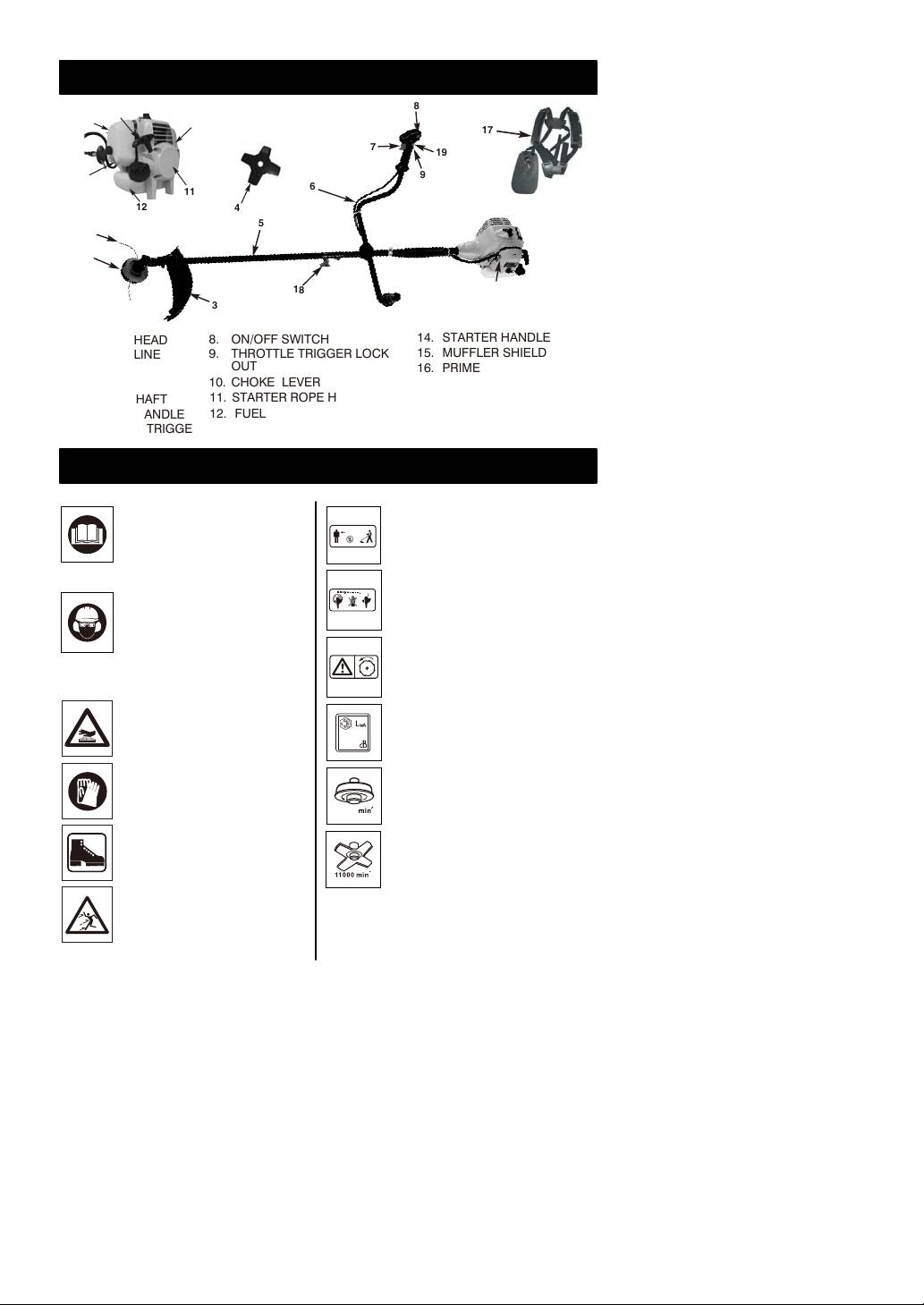
IDENTIFICATION (WHAT IS WHAT?)
17
4
1. TRIMMER HEAD
8. ON/OFF SWITCH
14. STARTER HANDLE
2. TRIMMER LINE
9. THROTTLE TRIGGER LOCK
15. MUFFLER SHIELD
3. SHIELD
OUT
16. PRIMER BULB
4. BLADE
10. CHOKE LEVER
17. SHOULDER HARNESS
5. OUTPUT SHAFT
11. STARTER ROPE HOUSING
18. COUPLER
6. “Bullhorn” HANDLE
12. FUEL TANK
19. THROTTLE LOCK
7. THROTTLE TRIGGER
13. AIR FILTER COVER
IDENTIFICATION OF SYMBOLS
Read and understand the Instr-
Keep people or animals at least
uction Manual and all warning
15m away from the machine
labels before using the machine.
during operation
Whenever the machine is in use,
WARNING: Cutting elem-
safety glasses must be worn to
safeguard against flying objects.
ents continue to rotate after the
Ear protection must also be used
engine turned off
in order to protect to operators
hearing. If the operator is
working in an area where there is
WARNING:
a risk of falling objects a safety
helmet must also be worn.
Rotating blades
Guaranteed sound power level
WARNING: Hot surface.
LWA accordance with directive
2000/14/EC + 2005/88/EC
Wear gloves to protect
your hands
Wear foot protection
Beware of thrown objects
-- 2 --
15m(50ft)
112
8
14
13
15
7
19
16
9
6
11
12
5
2
1
18
10
3
Maximum rotational frequency of
the spindle for cutting head
13300
Maximum rotational frequency of
the spindle for blade

SAFETY RULES
WARNING: When using gas tools,
• Check area you will be trimming for
basic safety precautions, including the
debris that may be struck or thrown
following, should always be followed to
during operation.
reduce the risk of serious personal injury
• Keep all parts of your body and
and/or damage to the unit. Read all these
clothing away from trimmer head when
instructions before operating this product
starting or running engine. Before starting
and save these instructions.
engine, make sure trimmer head will not
come in contact with any obstacle.
WARNING: This machine produces
• Stop engine before examining cutting
an electromagnetic field during operation.
line.
This field may under some circumstances
• Store equipment away from possible
interfere with active or passive medical
ignition sources ,such as gas-powered
implants. To reduce the risk of serious or
water heaters, clothes dryers, or oil-fired
fatal injury, we recommend persons with
furnaces, portableheaters, etc.
medical implants to consult their physician
• Aways keep the debris shield, trimmer
and the medical implant manufacturer
head, and engine free of debris build-up.
before operating this machine.
• Operation of equipment should always
be restricted to mature and properly
WHAT TO DO
instructed individuals.
READ YOUR USER MANUAL AND ALL
• WARNING: The emission of exhaust
SUPPLEMENTS (IF ANY ENCLOSED)
gases is toxic.
THOROUGHLY BEFORE OPERATING
• Emergency Stopping Procedure.When it
YOUR UNIT.
is necessary to stop engine immediately,
15m(50ft)
DEPRESS the switch to stop.
• This unit has a clutch. The routine for
checking that the clutch is working
correctly is that when the engine returns to
WARNING: Keep children, bystan-
idle the trimmer head stops spinning.
ders, and animals 50 feet (15 meters) away.
• Tighten the cap of oil and fuel tank to
If approached stop unit immediately.
prevent the loss of oil and fuel during
• Wear close fitting,tough work clothing
transport.
that will provide protection, such as long
• It is recommended that daily inspection
slacks or trousers, safety work shoes,
before use and after dropping or other
heavy duty work gloves, hard hat, a safety
impacts to prevent significant damage or
face shield, or safety glasses for eye
defects.
protection and a good grade of ear plugs
• Prolonged use of this product expose the
or other sound barriers for hearing
operator to vibrations and may produce
protection.
‘whitefinger’ disease. In order to reduce
• Prefuel in a safe place. Open fuel cap
the risk, please wear gloves and keep
slowly to release any pressure which may
your hands warm. If any of the
have formed in fuel tank. To prevent a fire
‘whitefinger’ symptoms appear, seek
hazard, move at least 10 feet (3 meters)
medical advice immediately.
from fueling area before starting.
BRUSH / GRASS BLADE SAFETY
• Comply with all fire prevention
PRECAUTIONS
regulations. Your unit comes with a spark
• FOLLOW ALL WARNINGS and
arrester screen furnished in the user
instructions regarding operation and blade
kit.Replacement spark arrester screen kits
installation.
are available from distributor.
• BLADE CAN VIOLENTLY THRUST
• Turn unit off before setting it down.
AWAY FROM MATERIAL IT CANNOT
• Always hold unit firmly with both
CUT - Blade thrust can cause
hands, the thumb and fingers encircling
amputation of arms or legs. Keep
the handles.
people and animals 50 feet (15 meters)
• Keep all screws and fasteners tight.
away in all directions. If blade contacts
Never operate your equipment when it is
foreign objects during operation, turn off
improperly adjusted or not completely and
engine and allow coasting blade to stop.
securely assembled.
Then check blade for damage. Always
• Keep handles dry, clean and free of fuel
discard blade if it is warped or cracked.
mixture.
• BLADE THROWS OBJECTS VIOLE-
• Keep trimmer head as close to ground
NTLY - You can be blinded or injured.
as practical. Avoid hitting small objects
Wear eye, face, and leg protection.
with trimmer head. When cutting on a
Always clear work area of any foreign
slope, stand below trimmer head. NEVER
objects before using blade. Keep people
cut or trim on a hill or slope, etc. If there is
and animals 50 feet (15 meters) away in
the slightest chance of slipping, sliding or
all directions.
losing firm footing.
-- 3 --

• INSPECT YOUR TRIMMER AND ATTA-
• DO NOT RAISE TRIMMER HEAD above
CHMENTS BEFORE EACH USE - Never
ground level while unit is operating. Injury
use unless all bladeattaching hardware is
to operator could result.
properly installed.
• DO NOT USE UNIT FOR ANY
• BLADE COASTS AFTER THROTTLE IS
PURPOSES OTHER than trimming lawn
RELEASED - A coasting blade can cut
or garden areas.
you or bystanders. Before performing any
• DO NOT OPERATE UNIT FOR PROL-
service on the blade, always turn off
ONGED PERIODS. Rest periodically.
engine, and be sure coasting blade has
• DO NOT OPERATE UNIT WHILE
stopped.
UNDER THE INFLUENCE OF ALCOHOL
• 50-FOOT (15 meters) DIAMETER HAZA-
OR DRUGS.
RD ZONE - Bystanders can be blinded or
• DO NOT OPERATE UNIT UNLESS
injured. Keep people and animals 50 feet
CUTTING ATTACHMENT GUARD AND/
(15 meters) away in all directions.
OR GUARD IS INSTALLED AND IN
GOOD CONDITION.
WHAT NOT TO DO
• DO NOT ADD, REMOVE OR ALTER ANY
• DO NOT USE ANY OTHER FUEL than
COMPONENTS OF THIS PRODUCT.
that recommended in your manual.
Doing so could cause personal injury
Always follow instructions in the Fuel and
and/or damage the unit voiding the
Lubrication section of this manual. Never
manufacturer’s warranty.
use gasoline unless it is properly mixed
• DO NOT operate your unit near or around
with 2-cycle engine lubricant. Permanent
flammable liquids or gases whether in or
damage to engine will result, voiding
out of doors. An explosion and/or fire may
manufacturer’s warranty.
result.
• DO NOT SMOKE while refueling or
• DO NOT USE ANY OTHER CUTTING
operating equipment.
ATTACHMENT. Use only replacement
• DO NOT OPERATE UNIT WITHOUT A
parts and accessories, which are design-
MUFFLER and properly installed muffler
ed specifically to enhance the performan-
shield.
ce and maximize the safe operation of our
• DO NOT TOUCH or let your hands or
products. Failure to do so may cause poor
body come in contact with a hot muffler or
performance and possible injury. Use only
spark plug wire.
the cutting head supplied with this
• DO NOT OPERATE UNIT IN AWKWARD
product. Do not use any other cutting
POSITIONS, off balance, outstretched
attachment. Use of such attachments will
arms, or one-handed. Always use two
void your factory warranty and could
hands when operating unit with thumbs
result in serious bodily injury.
and fingers encircling the handles.
ASSEMBLY
WARNING: Please assemble the
unit according to the assembly instructions.
Failure to do so may cause injury to the
operator.
“Bullhorn¨ HANDLE INSTALLATION
1. To install handle onto unit, you will need
the following components from your user
kit: “Bullhorn” handle (A), fixing holder (B),
clamp (C) and screws (D). (Fig.1A)
2. IInstall the fixing holder (B) between the
sponge sleeve (E and G), and adjust it to a
proper position.
3. Install the Bullhorn handle (A) on the fixing
holder, put the other clamp (C) over
bullhorn-handle, adjust handle to
appropriate position and tighten the other 2
INSTALLING THE ATTACHMENT
screws (D). The left handle shall be at least
200mm horizontally perpendicularly from
WARNING: To avoid serious
the shaft tube. The handle shaft must be
personal injury, shut unit off before
mounted on the right side of direction of
removing or installing attachment.
arrow head on the handle shaft. (Fig.1B)
NOTE: To make installing or removing the
4. Install wire tie (F) included in the user kit as
attachment easier, place the unit on the
shown (Fig.1C).
ground or on a work bench.
1. Turn the knob (A) counterclockwise to
loosen (Fig. 2A).
-- 4 --
90ß
G
D
C
B
A
E
C
D
Fig.1A
F
200mm
(minimum)
Fig.1B Fig.1C

2. While firmly holding the attachment (B),
CONFIGURING YOUR UNIT
push it straight into the Quick-Change
You can configure your unit using a cutting
coupler (C) until the release button (D)
head for grass and light weeds, or a weed
appears in the primary hole (E) of the
blade for cutting grass, weeds, and brush up
Quick-Change coupler. (Fig. 2B)
to 1 cm in diameter. To assemble your unit,
3. Turn the knob (A) clockwise to tighten.
go to the section for the desired
(Fig. 2C)
configuration and follow the instructions.
CAUTION: The release button must
ASSEMBLY INFORMATION -
be in the primary hole and the knob securely
TRIMMER HEAD
tightened before operating this unit.
All attachments are designed to be used in
the primary hole unless otherwise indicated
in the specific attachments operators
TRIMMER
manual. If the incorrect hole is used, it could
HEAD
result in injury, or damage to the unit.
A
C
B
C
B
E
D
D
E
Fig. 2A Fig. 2B
NOTE: Remove the blade before attaching
the trimmer head. To remove blade, align
hole in the dust cup with the hole in the side
of the gearbox by rotating the blade. Insert a
small screwdriver into aligned holes. This
will keep the shaft from turning while
loosening the blade nut. Remove blade nut
by turning clockwise. Remove the
Fig. 2C
screwdriver. Remove both washers and
ATTACHING THE SHIELD
blade. See INSTALLATION OF THE
METAL BLADE for illustrations. Be sure to
WARNING: The shield must be
store all parts and instructions for future
properly installed. The shield provides
use. Never use the trimmer head with the
partial protection to the operator and thers
metal blade installed.
from the risk of thrown objects, and is
INSTALLATION OF THE TRIMMER
equipped with a line limiter blade which cuts
excess line to the proper length.
HEAD
The line limiter blade (on underside of
NOTE: If your unit has a plastic cover over
shield) is sharp and can cut you.
the threads on the threaded shaft, remove
1. Insert bracket into slot on shield.
the covering to expose the threads. Before
2. Pivot shield to align holes in shield and
installing the trimmer head, make sure the
bracket.
dust cup and retaining washer are
positioned on the gearbox.
Bracket
Gearbox
Shield
Slot
Shield
Aligned holes
Dust cup
3. Secure shield to bracket with bolt.
Retaining washer
NOTE: Make sure all parts are properly
installed as shown in the illustration before
installing the trimmer head.
Bolt
1. Align hole in the dust cup with the hole in
the side of the gearbox by rotating the
dust cup.
-- 5 --

2. Insert a small screwdriver into aligned
5. Install the blade nut by threading onto the
holes. This will keep the shaft from
shaft counterclockwise.
turning while tightening trimmer head.
3. While holding the screwdriver in position,
Shield
Gearbox
thread trimmer head onto the shaft in the
direction shown on the decal
(counterclockwise). Tighten until secure.
NOTE: The retaining washer must be
Dust cup
positioned with the raised section facing
toward the gearbox.
Threaded
ASSEMBLY INFORMATION -
Aligned holes
shaft
WEED BLADE
WEED
BLADE
Retaining washer
Blade
Cupped washer
Nut
Wrench
NOTE: Make sure all parts are in place as
illustrated, and the blade is sandwiched
between the dust cup and the retaining
NOTE: Remove the trimmer head before
washer. There should be no space between
installing the weed blade. To remove the
the blade and the dust cup or the retaining
trimmer head, align hole in the dust cup with
washer.
the hole in the side of the gearbox by
6. Align hole in dust cup with hole in side of
rotating the dust cup. Insert a small
gearbox by rotating the blade.
screwdriver into aligned holes. This will
7. Insert a small screwdriver into aligned
keep the shaft from turning while loosening
holes. This will keep the shaft from
the trimmer head. Remove the trimmer
turning while tightening the blade nut.
head by turning clockwise. Remove the
8. Tighten blade nut firmly with wrench
screwdriver.
(provided) while holding screwdriver in
See INSTALLATION OF THE CUTTING
position.
HEAD for illustrations. Be sure to store all
9. Remove the screwdriver.
parts and instructions for future use.
10.Turn blade by hand. If the blade binds
INSTALLATION OF THE METAL
against the shield, or appears to be
BLADE
uneven, the blade is not centered, and
you must reinstall.
WARNING: Wear protective gloves
NOTE: To remove blade, insert screwdriver
when handling or performing maintenance
into aligned holes. Unthread the nut and
on the blade to avoid injury. The blade is
remove parts. Be sure to store parts and
sharp and can cut you even when it is not
instructions for future use.
moving.
REMOVE AND INSTALLATION THE
WARNING: Do not use any blades,
BLADE COVER
or fastening hardware other than the
washers and nuts shown in the following
CAUTION: Before you take apart the
illustrations. These parts must be provided
blades, wear gloves to prevent any danger.
and installed as shown below. Failure to use
proper parts can cause the blade to fly off
CAUTION: When the machine is not
and seriously hurt you or others.
in use or in transportation, make sure
NOTE: The dust cup is located on the
blades have been covered.
gearbox shaft and not in the parts bag. All
1. Before assembling blades, please
other fasteners mentioned in the following
remove the blades cover first.
assembly steps are in the parts bag.
2. Refer figure 6A and Figure 6B, hold the
1. Install the blade and the retaining washer
blades cover, and pull sligtly the cover
over the threaded shaft.
outward the cover can be taken apart.
2. Make sure the raised part of the retaining
3. Refer to figure 6C and 6D, and assemble
washer is facing the gearbox and the
in the opposite way to cover the blades.
raised area fits into the hole in the center
of the blade.
3. Slide the blade and retaining washer
onto the shaft of the gearbox.
4. Place the cupped washer onto the shaft.
Make sure the cupped side of the washer
is toward the blade.
Fig. 6A Fig. 6B
-- 6 --

Fig. 6C Fig. 6D
FUEL AND LUBRICATION
IMPORTANT
WARNING: Never use straight petrol
Use of alcohol blended fuels (called gasohol
in your unit. This will cause permanent
or using ethanol or methanol) can cause
engine damage and void the manufacturer’s
major enging performance and durability
warranty for that product. Never use a fuel
problems.
mixture that has been stored for over 90
days.
WARNING: Alternative fuels (not
petrol) such as E-15 (15% alcohol), E-20 (20%
WARNING: Lubricant must be a
alcohol), E-85 (85% alcohol) are NOT
premium grade oil for 2-stroke air cooled
classified as petrol and are NOT approved for
engines mixed at a 40:1 ratio. Do not use
use in 2-stroke petrol engines. Use of
any 2-cycle oil product with a recommended
alternative fuels will cause problems such as:
mixing ratio of 100:1. If insufficient lubrication
improper clutch engagements, overheating,
is the cause of engine damage, it voids the
vapor lock, power loss, lubrication deficiency,
manufacturer’s engine warranty.
deterioration of fuel lines, gaskets and internal
carburetor components, etc. Alternative fuels
WARNING: Lack of lubrication voids
cause high moisture absorption into the
engine warranty. Gasoline and oil must be
fuel/oil mixture leading to oil and fuel
mixed at 40:1.
separation.
WARNING: Remove fuel cap slowly
FUEL AND LUBRICATION
when refueling.
This engine is certified to operate on unleaded
petrol. Before operation, petrol must be mixed
with a good quality 2-cycle air-cooled engine
oil designed to be mixed at a ratio of 40:1. A
Gasoline and
Oil Mix 40:1
40:1 ratio is obtained by mixing 5 liters of
unleaded petrol with 0,125 liter of oil. DO NOT
USE automotive oil or marine oil. These oils
will cause engine damage. When mixing fuel,
FUEL MIXING TABLE
follow instructions printed on oil container.
Once oil is added to petrol, shake container
GASOLINE 40:1 Ratio Lubricant
momentarily to assure that the fuel is
1 U.S. Gal. 3.2 oz. 95ml (cc)
thoroughly mixed. Always read and follow the
safety rules relating to fuel before fueling your
5 Liters 4.3 oz. 125ml (cc)
unit.
1 lmp.Gal. 4.3 oz. 125ml (cc)
FUEL REQUIREMENTS
Mixing
40 Parts Gasoline
Use good quality unleaded petrol. The lowest
Procedure
to 1 part Lubricant
recommended octane grade is 90 (RON).
1ml = 1cc
OPERATING INSTRUCTIONS
SHOULDER HARNESS
1. The shoulder straps are on your both
shoulders. NOTE: Pull the black strip(E)
WARNING: ALWAYS WEAR SHOU-
in order to quickly release the harness
LDER HARNESS when operating unit with a
from the operator in the event of
blade. Attach harness to trimmer after
emergency. (Fig 8A)
starting unit and engine is running at IDLE.
2. Attach the harness clip (C) to the ring (D)
Turn ENGINE OFF before disconnecting
mounted on the shaft (Fig. 8B and 8C).
shoulder harness.
3. Adjust length of shoulder strap so trimmer
NOTE: When you install the cutting
head is parallel to the ground as it hangs
attachment, please follow the below
from the strap. A few practice swings
requirements.
without starting engine should be made to
determine correct balance.
-- 7 --

NOTE: Detach the shoulder harness from
5. Wait 10 sec.
the unit before starting engine.
6. A smooth rapid pull is required for a strong
spark. Pull starter rope briskly 6 times
(max) (Fig. 9F)
7. Move choke lever to HALF CHOKE
“ ”position as soon as the engine sounds
as if it is trying to start (Fig. 9G).
PUSH
8. Pull starter rope again while trigger is in
the full throttle position until engine starts.
Fig. 8A
(Fig. 9F)
9. Once engine is started, leave the choke
lever in the HALF CHOKE “ ” position for
20 seconds, then move choke lever to
RUN “ ”. If engine does not start, go back
to step 2.
NOTE: If engine fails to start after repeated
attempts, refer to Troubleshooting section.
OPERATING POSITION
NOTE: Always pull starter rope straight out.
ALWAYS WEAR:
Safety helmet
Pulling starter at an angle will cause rope to
Hearing
rub against the eyelet. This friction will cause
protection
the rope to fray and wear more quickly.
Eye protection
Always hold starter handle when rope
retracts. Never allow rope to snap back from
extended position. This could cause rope to
snag or fray and also damage the starter
Heavy,
assembly.
long pants
13cm
Boots
For blade
For String
Cut from your right to your left.
100-400mm
Head
0-300mm
When operating unit, clip shoulder strap onto
clamp, stand as shown and check for the
Fig. 9A Fig. 9B
following:
- Wear eye protection and heavy clothing.
A
- Extend your left arm and hold bullhorn
handle with your left hand.
- Hold throttle grip with your right hand with
finger on throttle trigger.
- Keep unit below waist level.
Fig. 9C Fig. 9D
- Keep shoulder strap pad centered on your
left shoulder.
- Maintain full weight of tool on your left
shoulder.
- Without bending over, keep the blade or
trimmer head near and parallel to the
ground and not crowded into material
being cut.
Fig. 9E Fig. 9F
STARTING A COLD ENGINE
NOTE: To minimize load on engine during
starting and warm-up, trim excess cutter line
to 13cm (Fig. 9A).
1. Press ON/OFF switch to the “RUN (I)”
position (Fig.9B).
2. Your unit is designed with a 3 position
Fig. 9G Fig. 9H
choke: FULL CHOKE “ ”, HALF CHOKE
“ ”, and RUN “ ”. Move choke lever to
FULL CHOKE “ ” position (Fig. 9C).
1. Move switch to the “RUN” position
3. Set throttle lock (C): Press the lockout
(Fig.10A).
switch (A) down and then holding trigger
2. Place choke in HALF CHOKE “ ” position
(B) at partially open position, press down
(Fig. 10B).
and hold throttle lock (C). Release throttle
trigger (B). Throttle trigger (B) will now
3. Grasp throttle handle firmly, squeeze throttle
remain in the partially depressed position
trigger to FULL position.
(Fig. 9B).
4. Pull starter rope briskly until engine starts,
4. Press the primer bulb (A) 10 times (Fig.
but no more than 6 times. Keep throttle at
9D).
FULL position until engine runs smoothly.
-- 8 --
E
C
D
Fig. 8B
Fig.8C
C
A
B
A
B
WARM ENGINE START

5. If engine does not start, place choke in RUN
“ ” position and pull starter rope 5 more
times. If engine still does not start it is
probably flooded. Wait 5 minutes and repeat
procedure with choke in RUN “ ” position
and throttle full open.
Fig. 10BFig. 10A
TO STOP ENGINE
Release throttle trigger. Let engine return to
idle. Push and hold ignition stop switch until
engine stops.
TRIMMER INSTRUCTIONS
OPERATING INSTRUCTIONS FOR
Tip of line does
Line crowded into
USE WITH TRIMMER HEAD
the cutting.
work area.
WARNING: Always wear eye
protection. Never lean over the trimmer
head. Rocks or debris can ricochet or be
thrown into eyes and face and cause
blindness or other serious injury.
Before trimming, bring engine to a speed
sufficient to cut material to be trimmed.
Do not run the engine at a higher speed than
Right Wrong
necessary. The cutting line will cut efficiently
- The line will easily remove grass and
when the engine is running at less than full
weeds from around walls, fences, trees
throttle. At lower speed, there is less engine
and flower beds, but it also can cut the
noise and vibration. The cutting line will last
tender bark of trees or shrubs and scar
longer and will be less likely to “weld” onto
fences.
the spool.
- For trimming or scalping, use less than
Always release the throttle trigger and allow
full throttle to increase line life and
the engine to return to idle speed when not
decrease head wear, especially:
cutting.
- During light duty cutting.
To stop engine:
- Near objects around which the line can
- Release the throttle trigger.
wrap such as small posts, trees or fence
- Push and hold the ON/STOP switch in the
wire.
STOP position until the engine stops.
- For mowing or sweeping, use full throttle
TRIMMER LINE ADVANCE
for a good clean job.
Advance line by tapping the bottom of the
TRIMMING - Hold the bottom of the trimmer
cutting head lightly on the ground while engine
head about 8 cm above the ground and at
is running at full speed. The metal line limiter
an angle. Allow only the tip of the line to
blade attached to the guard will cut the line to
make contact. Do not force trimmer line into
the proper length.
work area.
WARNING: Use only 2,4 mm diameter
Trimming
line. Other sizes of line will not advance
properly and will result in improper cutting head
function or can cause serious injury. Do not use
other materials such as wire, string, rope, etc.
Wire can break off during cutting and become a
dangerous missile that can cause serious
injury.
8 cm above
ground
CUTTING METHODS
SCALPING - The scalping technique
WARNING: Use minimum speed and
removes unwanted vegetation down to the
do not crowd the line when cutting around
ground. Hold the bottom of the trimmer head
hard objects (rock, gravel, fence posts, etc.),
about 8 cm above the ground and at an
which can damage the trimmer head,
angle. Allow the tip of the line to strike the
become entangled in the line, or be thrown
ground around trees, posts, monuments,
causing a serious hazard.
etc. This technique increases line wear.
- The tip of the line does the cutting. You will
achieve the best performance and
minimum line wear by not crowding the
line into the cutting area. The right and
wrong ways are shown below.
-- 9 --

Scalping
TRIMMING PROCEDURES
When properly equipped with a cutting
attachment guard and cutting head, your unit
will trim unsightly weeds and tall grass in
those hard-to-reach areas - along fences,
walls, foundations and around trees. It can
also be used for scalping to remove
vegetation down to the ground for easier
preparation of a garden or to clean out a
MOWING - Your trimmer is ideal for mowing
particular area.
in places conventional lawn mowers cannot
NOTE: Even with care, trimming around
reach. In the mowing position, keep the line
foundations, brick or stone walls, curves,
parallel to the ground. Avoid pressing the
etc., will result in above normal string wear.
head into the ground as this can scalp the
TRIMMING / MOWING
ground and damage the tool.
Swing trimmer with a sickle-like motion from
Mowing
side to side. Do not tilt the cutting head during
the procedure. Test area to be trimmed for
proper cutting height. Keep cutting head at
same level for even depth of cut (Fig. 12A).
SWEEPING - The fanning action of the
rotating line can be used to blow away loose
debris from an area. Keep the line parallel to
and above the area surface and swing the
tool from side to side.
Sweeping
Fig. 12A
OPERATING INSTRUCTIONS FOR USE WITH BLADE
• Blade Thrust is a reaction that only occurs
the blade snags, stalls, or binds. This is
when using a bladed unit. This reaction
more likely to occur in areas where it is
can cause serious injury such as
difficult to see the material being cut. By
amputation. Carefully study this section. It
using the unit properly, the occurrence of
is important that you understand what
blade thrust will be reduced and the
causes blade thrust, how you can reduce
operator will be less likely to lose control.
the chance of its occurring, and how you
can remain in control of unit if blade thrust
occurs.
• WHAT CAUSES BLADE THRUST -
Blade Thrust can occur when the spinning
blade contacts an object that it does not
cut. This contact causes the blade to stop
for an instant and then suddenly move or
“thrust” away from the object that was hit.
The “thrusting” reaction can be violent
• Cut only grass, weeds, and woody brush
enough to cause the operator to be
up to 1 cm in diameter with the weed
propelled in any direction and lose control
blade. Do not let the blade contact
of the unit. The uncontrolled unit can cause
material it cannot cut such as stumps,
serious injury if the blade contacts the
rocks, fences, metal, etc., or clusters of
operator or others.
hard, woody brush having a diameter
• WHEN BLADE THRUST OCCURS -
greater than 1 cm.
Blade Thrust can occur without warning if
-- 10 --

• Keep the blade sharp. A dull blade is more
Always release the throttle trigger and allow
likely to snag and thrust.
engine to return to idle speed when not
• Cut only at full throttle. The blade will have
cutting. The blade should not turn while the
maximum cutting power and is less likely
engine is running at idle. If the blade turns at
to bind or stall.
idle, do not use your unit. Refer to the
• “Feed” the blade deliberately and not too
CARBURETOR ADJUSTMENT section or
rapidly. The blade can thrust away if it is
contact your authorized service dealer.
fed too rapidly.
• Maintain good firm footing while using the
• Cut only from your left to your right.
unit. Do this by planting feet firmly in a
Cutting on right side of the shield will
comfortable apart position.
throw debris away from the operator.
• Cut while swinging the upper part of your
• Use the shoulder strap and keep a firm
body from right to left.
grip on the unit with both hands. A
• As you move forward to the next area to
properly adjusted shoulder strap will
cut, be sure to maintain your balance and
support the weight of the unit, freeing your
footing.
arms and hands to control and guide the
RECOMMENDED CUTTING POSITION
cutting motion.
2 o’clock
• Keep feet comfortably spread apart and
braced for a possible sudden, rapid thrust
Cut using the 2
of unit. Do not overreach. Keep firm
o’clock to 4 o’clock
footing and balance.
position of the
4 o’clock
• Keep blade below waist level; it will be
blade
easier to maintain control of unit.
• Do not raise the engine above your waist
as the blade can come dangerously close
WARNING: The operator or others
to your body.
must not try to clear away cut material with
• Do not swing unit with such force that you
the engine running or the blade turning to
are in danger of losing your balance.
avoid serious injury. Stop engine and blade
Bring the engine to cutting speed before
before removing materials wrapped around
entering the material to be cut. If the blade
blade or shaft.
does not turn when you squeeze the throttle
trigger, make sure shaft is fully inserted into
the engine.
MAINTENANCE INSTRUCTIONS
REPLACING THE LINE
2. Remove any remaining line.
1. Press the tabs on the side of the trimmer
3. Clean dirt and debris from all parts.
head and remove cover and spool.
Replace spool if it is worn or damaged.
4. Replace with a pre-wound spool, or
replace line using a 4,5 meters length of
2,4 mm diameter line.
WARNING: Never use wire, rope,
string, etc., which can break off and become
a dangerous missile.
5. When installing new line on an existing
spool, hold the spool as shown.
6. Bend the line at the midpoint and insert the
bend into the slot in the center rim of the
spool. Ensure line snaps into position in
Tab
Tab
the slot.
Slot
Cover
Spool
-- 11 --

7. With your finger between the lines, wrap
the lines evenly and firmly around the
spool in a clockwise direction.
8. Position the lines in the guide slots.
Guide slot
Guide slot
BLADE REPLACEMENT
Refer to the ASSEMBLY section for blade
replacement instructions and illustrations.
CARBURETOR ADJUSTMENT
9. Place the spool in the cover as shown
below.
WARNING: Keep others away when
making idle speed adjustments. The trimmer
head will be spinning during most of this
procedure. Wear your protective equipment
and observe all safety precautions. After
making adjustments, the trimmer head must
not move/spin at idle speed. The carburetor
has been carefully set at the factory.
Adjustments may be necessary if you notice
any of the following conditions:
- Engine will not idle when the throttle is
released.
10
.Insert the ends of the lines through exit
- The trimmer head moves/spins at idle
holes in the sides of the cover.
speed.
Make adjustments with the unit supported so
Line exit hole
the cutting attachment is off the ground and
will not make contact with any object. Hold
the unit by hand while running and making
adjustments. Keep all parts of your body
away from the cutting attachment and
muffler.
Idle Speed Adjustment
Cover
Allow engine to idle. Adjust speed until
engine runs without trimmer head moving or
11.Reinstall the spool and cover onto the
spinning (idle speed too fast) or engine
trimmer head. Push until cover snaps into
stalling (idle speed too slow).
place.
- Turn idle speed screw clockwise to
increase engine speed if engine stalls or
dies.
- Turn idle speed screw counterclockwise to
decrease engine speed if trimmer head
moves or spins at idle speed.
-- 12 --

SPARK PLUG
WARNING: Recheck the idle speed
1. Spark plug gap = .025" (.635mm) (Fig.18).
after each adjustment. The trimmer head
2. Torque to 105 to 130 inch pounds (12 to 15
must not move or spin at idle speed to avoid
N•m). Connect spark plug boot.
serious injury to the operator or others.
E
F
AIR FILTER
CAUTION: NEVER operate trimmer
without the air filter. The air filter must be kept
clean. If it becomes damaged, install a new
filter.
To Clean Air Filter:
Fig. 18 Fig. 19
1. Remove knob (A) holding air filter cover in
CUTTING ATTACHMENT GUARD
place, remove cover (B) and lift filter (C)
from air box (Fig. 16).
KNIFE SHARPENING
2. Wash filter in soap and water. DO NOT
1. Remove cutter knife (A) from cutting
USE GASOLINE!
attachment guard (B) (Fig.19).
3. Air dry filter.
2. Place knife in a bench vise. Sharpen knife
4. Reinstall filter.
using a flat file, being careful to maintain
NOTE: Replace filter if frayed, torn, damaged
the angle of cutting edge. File in one
or unable to be cleaned.
direction only.
A
B
STORING A UNIT
C
WARNING: Failure to follow these
steps may cause varnish to form in the
carburetor and difficult starting or permanent
damage following storage.
1. Perform all the general maintenance
Fig. 16
recommended in the Maintenance Section
of your User Manual.
FUEL CAP / FILTER
2. Clean exterior of engine, Output Shaft,
CAUTION: Remove fuel from unit and
cutting attachment guard and cutting head.
store in approved container before starting
3. Drain fuel from the fuel tank.
this procedure. Open fuel cap slowly to
4. After fuel is drained, start engine.
release any pressure which may have formed
5. Run engine at idle until unit stops. This will
in fuel tank.
purge the carburetor of fuel.
1. Completely remove fuel cap (A) from fuel
6. Allow engine to cool (approx. 5 minutes).
tank (B) to be able to remove fuel filter (D)
7. Using a spark plug wrench, remove the
from tank. Use a piece of wire (C) with a
spark plug.
hook formed at the end to pull filter out of
8. Pour 1 teaspoon of clean 2-cycle oil into
tank. (Fig.17A & Fig.17B)
the combustion chamber. Pull starter rope
2. Pull filter (D) off with a twisting motion.
slowly several times to coat internal
3. Replace fuel filter (D). (Fig.17C)
components. Replace spark plug.
9. Store unit in a cool, dry place away from
NOTE: Never operate the trimmer without
any source of ignition such as an oil
the fuel filter. Internal engine damage could
burner, water heater, etc.
result!
REMOVING A UNIT FROM STORAGE
A
C
1. Remove spark plug.
2. Pull starter rope briskly to clear excess oil
from combustion chamber.
3. Clean and gap spark plug or install a new
B
spark plug with proper gap.
4. Prepare unit for operation.
Fig. 17A Fig. 17B
5. Fill fuel tank with proper fuel / oil mixture.
See Fuel and Lubrication Section.
D
Fig. 17C
-- 13 --

TROUBLESHOOTING TABLE
WARNING:
Always stop unit and disconnectspark plug before performingall ofthe
recommended remedies below except remedies that require operation of the unit.
PROBLEM
PROBABLE CAUSE
CORRECTIVE ACTION
Unit won’t start or
Incorrect starting procedures.
Follow instructions in the User Manual.
starts but will not run.
Incorrect carburetor mixture
Have carburetor adjusted by an Authorized
adjustment setting.
Service Center.
Fouled spark plug
Clean / gap or replace plug.
Fuel filter plugged.
Replace fuel filter.
Unit starts, but engine
Incorrect lever position on choke.
Move to RUN position.
has low power.
Dirty spark arrester screen.
Replace spark arrester screen.
Dirty air filter.
Remove, clean and reinstall filter.
Incorrect carburetor mixture
Have carburetor adjusted by an Authorized
adjustment setting.
Service Center.
Engine hesitates.
Incorrect carburetor mixture
Have carburetor adjusted by an Authorized
No power under load.
adjustment setting.
Service Center.
Runs erratically.
Incorrectly gapped spark plug.
Clean / gap or replace plug.
Smokes excessively.
Incorrect carburetor mixture
Have carburetor adjusted by an Authorized
adjustment setting.
Service Center.
Incorrect fuel mixture.
Use properly mixed fuel (40:1 mixture).
-- 14 --

DECLARATION OF CONFORMITY
Business name of the manufacturer: Husqvarna AB
Full address of the manufacturer: SE-561 82 Huskvarna, Sweden
We declare that the machinery
Product name: Grass trimmer, Gasoline
Commercial name: Gasoline trimmer
Function: Trimming grass
Model: B305 CBS
Type: Powered by gasoline
Fulfils all the relevant provisions of Directives
2006/42/EC, 2004/108/EC, 2000/14/EC+2005/88/EC,
97/68/EC+2004/26/EC
and tested in accordance with below standards
EN ISO 11806:2011
EN ISO 14982:2009
The conformity assessment of Directive 2000/14/EC, was done using
Annex V of the Directive. For information regarding noise emissions
and rated net power, see Technical Data Sheet.
Person authorised to compile the technical file and make
this declaration:
Name, surname : Bo R Jonsson
Position/Title : R&D Manager
Address : SE-561 82 Huskvarna, Sweden
Place and date of the declaration: Shanghai, PRC 2013/1/18
-- 15 --

TECHNICAL DATA SHEET
Model No. . . . . . . . . . . . . . . . . . . . . . . . . . . . . . . . . . . . . . . . . . . . . . . . . . . . B305 CBS
Engine Type . . . . . . . . . . . . . . . . . . . . . . . . . . . . . . . . . . . . . . . . . . . . . . . . . . . . . . . . . . Air-cooled, 2-Cycle
. . . . . . . . . . . . . . . . . . . . . . . . . . . . . . . . . . . . . . . . . . . . . . . . . . . . . . . . . . Chrome Cylinder
Displacement . . . . . . . . . . . . . . . . . . . . . . . . . . . . . . . . . . . . . . . . . . . . . . . . . . . . . . . . . 30 cm
3
Dry Weight (without fuel, cutting attachment and guard) . . . . . . . . . . . . . . . . . . . . . . . . 6.35 Kg
Fuel Capacity . . . . . . . . . . . . . . . . . . . . . . . . . . . . . . . . . . . . . . . . . . . . . . . . . . . . . . . . . .550cm
3
Bump Head . . . . . . . . . . . . . . . . . . . . . . . . . . . . . . . . . . . . . . . . . . . . . . . . . . . . . . . . . . . Twin Line Bump Feed
Blade 4 Teeth . . . . . . . . . . . . . . . . . . . . . . . . . . . . . . . . . . . . . . . . . . . . . . . . . . . . . . . . . 4 Teeth
Drive ShaftLength . . . . . . . . . . . . . . . . . . . . . . . . . . . . . . . . . . . . . . . . . . . . . . . . . . . . . . 66cm + 66cm
Cutting Width (Twin Line Head) . . . . . . . . . . . . . . . . . . . . . . . . . . . . . . . . . . . . . . . . . . . 43cm
(Blade) . . . . . . . . . . . . . . . . . . . . . . . . . . . . . . . . . . . . . . . . . . . . . . . . . . 23cm
Handle . . . . . . . . . . . . . . . . . . . . . . . . . . . . . . . . . . . . . . . . . . . . . . . . . . . . . . . . . . . . . . “Bullhorn” Handle
Ignition . . . . . . . . . . . . . . . . . . . . . . . . . . . . . . . . . . . . . . . . . . . . . . . . . . . . . . . . . . . . . . Electronic
Drive . . . . . . . . . . . . . . . . . . . . . . . . . . . . . . . . . . . . . . . . . . . . . . . . . . . . . . . . . . . . . . . . Centrifugal Clutch
Sound levels (see note 1)
Equvialent sound pressure level at the operators ear . . . . . . . . . . . . . . . . . . . . . . . . . . . 96.59 dB(A)
Noise emissions (see note 2)
Measured sound power level . . . . . . . . . . . . . . . . . . . . . . . . . . . . . . . . . . . . . . . . . . . . . .109.43 dB(A)
Guaranteed sound power level . . . . . . . . . . . . . . . . . . . . . . . . . . . . . . . . . . . . . . . . . . . . 112 dB(A)
Equivalent vibration(left/right handles) (K=1.5) . . . . . . . . . . . . . . . . . . . . . . . . . . . . . . . 4.987/4.460 m/s
2
Maximum Engine Performance . . . . . . . . . . . . . . . . . . . . . . . . . . . . . . . . . . . . . . . . . . . .0.89 kW
Engine Speed (rotational frequency) at recommended
max. spindle rotational frequency
(Bump Feed Head) . . . . . . . . . . . . . . . . . . . . . . . . . . . . . . . . . . . . . . . . . 9000 min
-1
(Blade) . . . . . . . . . . . . . . . . . . . . . . . . . . . . . . . . . . . . . . . . . . . . . . . . . . 11000min
-1
Maximum rotational frequency of the spindle
(Bump Feed Head) . . . . . . . . . . . . . . . . . . . . . . . . . . . . . . . . . . . . . . . . . 6700 min
-1
(Blade) . . . . . . . . . . . . . . . . . . . . . . . . . . . . . . . . . . . . . . . . . . . . . . . . . . 8200 min
-1
Idle speed . . . . . . . . . . . . . . . . . . . . . . . . . . . . . . . . . . . . . . . . . . . . . . . . . . . . . . . . . . . . 3000±300 min
-1
Specific fuel consumption . . . . . . . . . . . . . . . . . . . . . . . . . . . . . . . . . . . . . . . . . . . . . . . .415.3 g/kWh
Note 1: Equivalent sound pressure level, according to ISO 22868, is calculated as the time-weighted energy
total for different sound pressure levels under various working conditions. Typical statistical dispersion for
equivalent sound pressure level is a standard deviation of 1.5 dB (A).
Note 2: Noise emissions in the environment measured as sound power (Lwa) in conformity with EC
directive 2000/14/EC.
-- 16 --

1.
8.
14.
2.
9.
15.
3.
10.
16.
4.
11.
17.
5.
12.
18.
13.
6. Т-ОБРАЗНОЙ РУКОЯТКИ
7.
Люди и животные должны
находиться на расстоянии не
менее 15 м от инструмента во
время его эксплуатации.
При эксплуатации инструмента
ВНИМАНИЕ! Режущие
всегда необходимо надевать
детали продолжают
защитные очки для защиты от
вращаться после выключения
летящих предметов. Также опера-
двигателя.
тору необходимо использовать
средства защиты органов слуха.
При работе оператора в зоне
ВНИМАНИЕ!
риска падения предметов
Вращающийся нож!
необходимо одевать также
защитную каску.
Гарантируемый уровень
звуковой мощности LWA
соответствует требованиям
ВНИМАНИЕ!
2000/14/EC + 2005/88/EC
Горячая поверхность!
Надевайте защитные перчатки
для защиты рук.
-- 17 --
15m(50ft)
112
ОПИСАНИЕ ДЕТАЛЕЙ ИНСТРУМЕНТА
8
14
13
15
17
7
19
16
9
6
11
12
4
5
2
1
18
10
3
ТРИММЕРНАЯ ГОЛОВКА
ВЫКЛЮЧАТЕЛЬ
РУКОЯТКА СТАРТЕРА
ТРИММЕРНАЯ ЛЕСКА
ФИКСАТОР КУРКА ГАЗА
ЭКРАН ГЛУШИТЕЛЯ
ЩИТОК
РЫЧАГ ВОЗДУШНОЙ ЗАСЛОНКИ
КНОПКА ПОДСОСА
НОЖ
КОРПУС ШНУРА СТАРТЕРА
НАПЛЕЧНЫЙ РЕМЕНЬ
ШТАНГА
ТОПЛИВНЫЙ БАК
СОЕДИНИТЕЛЬ
КРЫШКА ВОЗДУШНОГО
19.
ФИЛЬТРА
ФИКСАТОР ДРОССЕЛЯ
КУРОК ГАЗА
ЗНАЧЕНИЕ СИМВОЛОВ
Перед использованием данного
инструмента внимательно
прочтите руководство по
эксплуатации и информацию на
предупреждающих наклейках.
Максимальная частота
вращения шпинделя для
триммерной головки.
13300
Максимальная частота
вращения шпинделя для ножа
Надевайте средства защиты ног.
Опасайтесь летящих предметов.

ПРАВИЛА ТЕХНИКИ БЕЗОПАСНОСТИ
•
Держите триммерную головку как можно
ВНИМАНИЕ!
При использовании
ближе к земле. Не допускайте
бензиновых инструментов необходимо
соприкосновения мелких предметов с
неукоснительно соблюдать основные правила
триммерной головкой. При стрижке травы на
техники безопасности (включая приведенные
наклонной поверхности становитесь ниже
ниже) для снижения риска причинения тяжелой
триммерной головки. КАТЕГОРИЧЕСКИ
травмы и (или) повреждения инструмента.
запрещается стричь траву или подрезать
Перед эксплуатацией данного изделия
кусты на возвышенности или на склоне и т.п.,
полностью прочтите настоящую инструкцию и
если существует даже малейшая вероятность
сохраните ее для дальнейшего использования.
скольжения, сползания или потери твердой
опоры под ногами.
ВНИМАНИЕ!
Данный инструмент во
•
Проверьте участок, на котором необходимо
время работы генерирует электромагнитное
подстричь траву, на предмет отсутствия
поле. Это поле при определенных обстоятельс-
предметов, о которые может удариться
твах может создавать помехи для работы
триммерная головка или которые могут
активных и пассивных медицинских импланта-
отлететь во время работы.
тов. Для снижения риска причинения тяжелого
•
При запуске и работе двигателя все части тела
или смертельного вреда здоровью лицам с
и одежда должны находиться вдали от
имплантированными медицинскими устройства-
триммерной головки. Перед запуском
ми перед эксплуатацией инструмента
двигателя убедитесь, что триммерная головка
рекомендуется проконсультироваться с их
не соприкасается с каким-либо препятствием.
лечащим врачом и производителем имплантата.
•
Выключайте двигатель перед осмотром
НЕОБХОДИМЫЕ ОПЕРАЦИИ
режущей лески.
•
Храните данный инструмент вдали от
ПЕРЕД ЭКСПЛУАТАЦИЕЙ ИНСТРУМЕ- НТА
возможных источников огня, таких как газовые
ВНИМАТЕЛЬНО ПРОЧТИТЕ РУКОВОДСТВО
колонки, сушилки одежды и печи, работающие
ПО ЭКСПЛУАТАЦИИ И ВСЮ
на жидком топливе, переносные нагреватели
СОПРОВОДИТЕЛЬНУЮ ДОКУМЕНТАЦИЮ
и т.п.
(ПРИ ЕЕ НАЛИЧИИ)
•
Всегда очищайте щиток, предохраняющий от
15m(50ft)
обрезков, триммерную головку и двигатель от
скопления мусора.
•
Эксплуатировать данный инструмент должны
только опытные и прошедшие надлежащий
ВНИМАНИЕ!
Дети, посторонние
инструктаж работники.
лица и животные должны находиться на
•
ВНИМАНИЕ! Выхлопные газы токсичны.
расстоянии 15 метров (50 футов) от
•
Процедура аварийного останова. При
инструмента. При их приближении необходимо
необходимости аварийного останова
незамедлительно выключить инструмент.
НАЖМИТЕ выключатель для
незамедлительного выключения двигателя.
•
Надевайте облегающую, крепкую рабочую
•
Данный инструмент оснащен муфтой
одежду, которая обеспечит защиту, например
сцепления. Если муфта сцепления работает
длинные брюки или штаны, защитную
надлежащим образом, при переходе
рабочую обувь, крепкие рабочие перчатки,
двигателя на холостой ход триммерная
защитную каску, защитную маску или
головка должна переставать вращаться.
защитные очки и качественные беруши или
•
Во избежание протечки масла и топлива при
другие средства защиты органов слуха.
транспортировке плотно закройте крышку
•
Заранее заправьте инструмент топливом в
масляного резервуара и топливного бака.
безопасном месте. Откройте крышку
•
Рекомендуется производить ежедневную
топливного бака, чтобы сбросить давление,
проверку перед использованием и после
которое могло образоваться в топливном
использования, после падения и других
баке. В целях пожарной безопасности перед
ударов во избежание значительных
началом работ переместитесь как минимум на
повреждений.
3 метра (10 футов) от места заправки.
•
При длительной работе этот продукт у
•
Соблюдайте все правила пожарной
оператора под воздействием вибрации может
безопасности. Данный инструмент поставл-
развиться вибрационная болезнь (синдром
яется с искрогасителем, входящим в комплект
белых пальцев). Работа в перчатках и
поставки. Сменные комплекты искрогаси-
поддержание теплоты рук снижают риск
телей можно приобрести у дистрибьютора.
развития вибрационной болезни. При
•
Выключайте инструмент перед тем, как
появлении симптомов вибрационной болезни
опустить его вниз.
незамедлительно обратитесь к врачу.
•
Всегда крепко удерживайте инструмент обе-
ими руками, обхватив рукоятки пальцами рук.
МЕРЫ ПРЕДОСТОРОЖНОСТИ ПРИ
•
Все винты и крепления должны быть плотно
ОБРАЩЕНИИ С НОЖОМ КУСТОРЕЗА-
затянуты. Категорически запрещается
ТРИММЕРА
использовать данный инструмент, если он
неправильно отрегулирован, либо
•
СОБЛЮДАЙТЕ ВСЕ МЕРЫ
неполностью или ненадежно собран.
ПРЕДОСТОРОЖНОСТИ и инструкции по
•
Руки должны быть сухими, чистыми и не
эксплуатации и установке ножей.
запачканными топливной смесью.
-- 18 --

•
НОЖ МОЖЕТ РЕЗКО ОТСКОЧИТЬ ОТ
•
ЗАПРЕЩАЕТСЯ КАСАТЬСЯ горячего
ПРЕДМЕТА, КОТОРЫЙ НЕ ПОДДАЕТСЯ
глушителя и провода свечи зажигания руками
РЕЗКЕ – отскок ножа может привести к
или другими частями тела.
ампутации конечностей. Люди и животные
•
ЗАПРЕЩАЕТСЯ ЭКСПЛУАТИРОВАТЬ ИНСТ-
должны находиться на расстоянии 15 метров
РУМЕНТ В НЕУДОБНЫХ ПОЛОЖЕНИЯХ, в
(50 футов) в любом направлении. Если нож
неустойчивом положении, с вытянутыми
коснулся постороннего предмета во время
руками или одной рукой. При работе
эксплуатации, выключите двигатель и дайте
инструментом всегда держите его двумя
движущемуся по инерции ножу остановиться.
руками, обхватив рукоятки пальцами рук.
Затем проверьте нож на предмет отсутствия
•
ЗАПРЕЩАЕТСЯ ПОДНИМАТЬ ТРИММЕРН-
повреждений. При обнаружении деформации
УЮ ГОЛОВКУ над уровнем земли при эксплу-
или трещин нож необходимо утилизировать.
атации инструмента. Это может привести
• НОЖ РЕЗКО ОТБРАСЫВАЕТ
получению травмы оператором.
ПРЕДМЕТЫ – это может привести к
•
ЗАПРЕЩАЕТСЯ ИСПОЛЬЗОВАТЬ ДАННЫЙ
получению травмы и потере зрения.
ИНСТРУМЕНТ ДЛЯ КАКИХ-ЛИБО ИНЫХ
Надевайте средства защиты глаз, лица и
ЦЕЛЕЙ, КРОМЕ стрижки лужаек и садовых
защитную обувь. Перед использованием
участков.
ножа очистите участок от посторонних
•
ЗАПРЕЩАЕТСЯ ЭКСПЛУАТИРОВАТЬ
предметов. Люди и животные должны
ДАННЫЙ ИНСТРУМЕНТ В ТЕЧЕНИЕ
находиться на расстоянии 15 метров (50
ДЛИТЕЛЬНОГО ВРЕМЕНИ. Необходимо
футов) в любом направлении.
периодически делать перерывы.
•
ПЕРЕД КАЖДЫМ ИСПОЛЬЗОВАНИЕМ
•
ЗАПРЕЩАЕТСЯ ЭКСПЛУАТИРОВАТЬ
ОСМАТРИВАЙТЕ БЕНЗОКОСУ И НАСАДКИ –
ДАННЫЙ ИНСТРУМЕНТ, НАХОДЯСЬ ПОД
категорически запрещается использование
ВОЗДЕЙСТВИЕМ АЛКОГОЛЯ ИЛИ
инструмента при неправильно установленных
НАРКОТИКОВ.
крепежных деталях ножа.
•
ЗАПРЕЩАЕТСЯ ЭКСПЛУАТИРОВАТЬ
•
НОЖ ПРОДОЛЖАЕТ ВРАЩАТЬСЯ ПО
ДАННЫЙ ИНСТРУМЕНТ С НЕПРАВИЛЬНО
ИНЕРЦИИ ПОСЛЕ ОТПУСКАНИЯ КУРКА
УСТАНОВЛЕННЫМ ИЛИ НЕИСПРАВНЫМ
ГАЗА – вращающийся по инерции нож может
КОЖУХОМ РЕЖУЩЕЙ НАСАДКИ.
причинить режущие травмы оператору или
•
ЗАПРЕЩАЕТСЯ ДОБАВЛЯТЬ, УДАЛЯТЬ И
окружающим. Перед выполнением
ИЗМЕНЯТЬ КАКИЕ-ЛИБО ДЕТАЛИ ДАННОГО
технического обслуживания ножа необходимо
ИЗДЕЛИЯ. Это может привести к получению
отключить двигатель и убедиться, что нож
травм и (или) повреждению инструмента, что
остановился.
аннулирует гарантию производителя.
•
ДИАМЕТР ОПАСНОЙ ЗОНЫ: 15 МЕТРОВ (50
•
ЗАПРЕЩАЕТСЯ эксплуатировать данный
футов) – нахождение в этой зоне может
инструмент рядом с горючими жидкостями
привести к получению травмы или потере
или газами и в их присутствии, как в закрытых
зрения. Люди и животные должны находиться
помещениях, так и на открытом воздухе. Это
на расстоянии 15 метров (50 футов) в любом
может привести к возгоранию и (или) взрыву.
направлении.
•
ЗАПРЕЩАЕТСЯ ИСПОЛЬЗОВАТЬ КАКИЕ-
ЛИБО ИНЫЕ РЕЖУЩИЕ НАСАДКИ. Исполь-
ZU VERMEIDEN
зуйте только запасные части и принадлежн-
•
ЗАПРЕЩАЕТСЯ ИСПОЛЬЗОВАТЬ КАКОЕ-
ости, предназначенные специально для
ЛИБО ИНОЕ ТОПЛИВО, кроме указанного в
повышения производительности и
настоящем руководстве. Неукоснительно
обеспечения максимальной безопасности
соблюдайте инструкции, приведенные в
эксплуатации изделий нашей компании.
разделе «Топливо и смазка» настоящего
Несоблюдение этого требования может
руководства. Категорически запрещается
привести к снижению производительности и
использовать бензин без его
риску получения травм. Используйте только
предварительного смешивания с маслом для
режущую головку, входящую в комплект
2-тактных двигателей. В противном случае
поставки данного изделия. Запрещается
произойдет повреждение двигателя, и будет
использовать какие-либо другие режущие
аннулирована гарантия производителя.
насадки. Использование других насадок
•
ЗАПРЕЩАЕТСЯ КУРИТЬ во время заправки и
приведет к аннулированию гарантии
эксплуатации данного инструмента.
производителя и может привести к получению
•
ЗАПРЕЩАЕТСЯ ЭКСПЛУАТИРОВАТЬ ИНСТ-
серьезной травмы.
РУМЕНТ БЕЗ ГЛУШИТЕЛЯ и надлежащим
образом установленного экрана глушителя.
СБОРКА
ВНИМАНИЕ!
Необходимо выполнить
УСТАНОВКА Т-ОБРАЗНОЙ РУКОЯТКИ
сборку инструмента в соответствии с
1. Для установки рукоятки на инструмент
инструкциями по сборке. Несоблюдение этого
потребуются следующие компоненты из
требования может привести к получению
комплекта поставки: T-образная рукоятка
травмы оператором.
(A), фиксирующий держатель (B), зажим (C)
и винты (D) (рис. 1A).
2. Установите фиксатор (B) между губчатым
рукавом (E и G) и отрегулируйте его
положение.
-- 19 --

Рисунок 2C
УСТАНОВКА ЩИТКА
ВНИМАНИЕ!
Необходимо
установить щиток надлежащим образом. Щиток
обеспечивает частичную защиту оператора и
других лиц от попадания летящих предметов.
Также щиток оснащен ножом для лески,
обрезающим леску до необходимой длины.
Нож для лески (расположенный на обратной
стороне щитка) острый, и об него можно
порезаться.
1.
Установите кронштейн в паз на щитке.
2.
Повернув щиток, совместите отверстия на
щитке и кронштейне.
Кронштейн
Паз
Щиток
УСТАНОВКА НАСАДКИ
3.
Закрепите щиток на кронштейне с помощью
болта.
ВНИМАНИЕ!
Во избежание
получения травм перед установкой или снятием
насадки необходимо выключать инструмент.
ПРИМЕЧАНИЕ: Для облегчения установки и
снятия насадки поместите инструмент на землю
или на верстак.
1. Ослабьте барашковый винт (A), повернув его
Болт
против часовой стрелки (рис. 2A).
2. Крепко удерживая насадку (B), вставьте ее в
быстроразъемный соединитель (C) так,
ВЫБОР КОНФИГУРАЦИИ
чтобы кнопка фиксатора (D) появилась в
основном отверстии (E) быстроразъемного
ИНСТРУМЕНТА
соединителя (рис. 2B)
Можно оснастить данный инструмент режущей
3. Затяните барашковый винт (A), повернув его
головкой для стрижки газонной и сорной травы
по часовой стрелке (рис. 2C).
или ножом для резки травы, сорняков и кустов
до 1 см в диаметре. Выполните инструкции по
ВНИМАНИЕ!
Перед эксплуатацией
сборке, приведенные в соответствующем
инструмента следует убедиться, что кнопка
разделе с описанием выбранной конфигурации
фиксатора находится в основном отверстии, а
инструмента.
барашковый винт надежно затянут.
Все насадки предназначены для установки в
ИНСТРУКЦИИ ПО СБОРКЕ –
основное отверстие, если иное не указано в
ТРИММЕРНАЯ ГОЛОВКА
руководстве по эксплуатации конкретной
насадки. Использование другого отверстия
может привести к причинению травм или
повреждению инструмента.
A
ТРИММЕРНАЯ
C
B
C
B
ГОЛОВКА
E
D
D
E
Рисунок 2A Рисунок 2B
-- 20 --
90ß
3. Установите Т-образную рукоятку (A) на
фиксирующий держатель, поместите сверху
рукоятки вторую часть зажима (C),
отрегулируйте положение рукоятки и
затяните два оставшихся винта (D) Левая
рукоятка должна располагаться на
расстоянии как минимум 200 мм по
горизонтали перпендикулярно трубке
штанги. Стержень рукоятки необходимо
установить с правой стороны от конца
стрелки на стержне рукоятки (рис.1B)
4. Установите хомут для провода (F), входящий
в комплект поставки, как показано на рис. 1C.
G
D
C
B
A
E
C
D
Рисунок 1A
F
200mm
(minimum)
Рисунок 1B Рисунок 1C