Makita LH1040F: instruction
Class: Tools, power tools and power equipment
Type: Power Saw
Manual for Makita LH1040F
Table Top Miter Saw
Instruction Manual
Universal-Kapp- und Gehrungssäge
Betriebsanleitung
Piła ukośnica ze stołem
Instrukcja obsługi
Настольная торцовочная пила
Инструкция по эксплуатации
LH1040
LH1040F
13
1
3
24
2
12
8
6
5
7
34
8
13
12
9
10
11
2
6
56
15
14
17
20
19
16
18
78
2
11
11
21
17
910
23
24
22
11 12
11
25
13 14
10
28
2
6
27
6
26
12
29
7
15 16
3
30
31
7
7
2
31
12
17 18
35
33
31
31
32
34
36
33
2
37
19 20
4-5 mm
8
38
39
2
2
21 22
45
38
43
40
41
44
2
42
23 24
4
AB
C
D
31
48
45
45
27
46
47
46
31
25 26
45
50
49
43
46
50
44
27 28
31
8
46
51
45
51
45
29 30
55
53
52
52
53
54
54
31 32
5
58
59
57
53
56
33 34
60
65
66
61
64
64
16
62
9
63
3
35 36
67
63
6362
37 38
68
68
39 40
6
68
71
69
70
62
16
69
9
41 42
10
250mm
130mm
200mm
55mm
80mm
50mm
10mm
73
30mm
10mm
100mm
72
30mm
74
9mm
75
57
43 44
77
140mm
15mm
78
10mm
14mm
40mm
300mm
73
70mm
76
79
77
45 46
81
80
82
47 48
7
25
49 50
2
83
16
19
51 52
31
59
83
14
11
84
53 54
85
11
11
85
59
1721
86
17
55 56
8
87
88
89
57 58
9

Symbols
The followings show the symbols used for the tool. Be sure that you understand their meaning before use.
Symbole
Die folgenden Symbole werden für die Maschine verwendet. Machen Sie sich vor der Benutzung unbedingt mit ihrer
Bedeutung vertraut.
Symbole
Poniższe symbole używane są do opisu urządzenia. Przed użyciem należy upewnić się, że rozumie się ich znaczenie.
Символы
Следующие объяснения показывают символы, используемые для инструмента. Убедитесь перед
использованием, что Вы понимаете их значение.
❏ Read instruction manual.
❏ Bitte Bedienungsanleitung lesen.
❏ Przeczytaj instrukcję obsługi.
❏ Прочитайте инструкцию по эксплуатации.
❏ DOUBLE INSULATION
❏ DOPPELT SCHUTZISOLIERT
❏ PODWÓJNA IZOLACJA
❏ ДВОЙНАЯ ИЗОЛЯЦИЯ
❏ To avoid injury from flying debris, keep holding the saw head down, after making cuts, until the
blade has come to a complete stop.
❏ Um Verletzungen durch herausgeschleuderte Teile zu vermeiden, halten Sie den Sägekopf nach
Ausführung von Schnitten abgesenkt, bis das Sägeblatt völlig zum Stillstand gekommen ist.
❏ Aby uniknąć zranienia odskakującymi odpadkami, po zakończeniu cięcia trzymaj głowicę piły w
dole, aż do całkowitego zatrzymania się brzeszczotu.
❏ Чтобы избежать травмы от летящих обрезков, удерживайте переднюю часть пилы,
обращенной вниз, после выполнения резки до тех пор, пока лезвие не остановится
полностью.
❏ When using the tool in the miter saw mode, secure the top table at the topmost blade never pro-
trudes from the top surface of the top table.
❏ Wenn Sie die Maschine im Gehrungssägenmodus verwenden, sichern Sie den oberen Tisch in
der Höchststellung, damit das Sägeblatt nicht über die Oberfläche des oberen Tisches hinaus-
ragt.
❏ W przypadku korzystania z urządzenia w trybie cięcia ukośnego, zamocuj stół górny tak, aby
brzeszczot nigdy nie wystawał poza górną powierzchnię stołu.
❏ При использовании инструмента в режиме торцовочной пилы закрепите верхний стол в
самом верхнем положении так, чтобы лезвие никогда не выступало на верхней
поверхности верхнего стола.
❏ For your safety, remove chips, small pieces, etc. from the table top before operation.
❏ Zur Sicherheit sollte die Tischplatte vor dem Betrieb von Spänen, Kleinteilen usw. gesäubert wer-
den.
❏ Dla bezpieczeństwa przed przystąpieniem do pracy usuń strużyny, małe odpady itp. z
powierzchni stołu.
❏ Для Вашей безопасности удалите стружки, маленькие куски и т.д. со стола перед
эксплуатацией.
❏ Do not place hand or fingers close to the blade.
❏ Halten Sie Hände oder Finger vom Sägeblatt fern
❏ Nie zbliżaj rąk i palców do brzeszczotu.
❏ Не помещайте руки или пальцы близко к лезвию.
10

ENGLISH
Explanation of general view
1 Auxiliary plate
32 Blade case
63 Holder assembly
2Hex bolt
33 Arrow
64 Vise knob
3Base
34 Outer flange
65 Projection
4Nut
35 Inner flange
66 Vise shaft
5Bolt
36 Spindle
67 Rod 12
6 Lower blade guard A
37 Ring
68 Vise (optional accessory)
7 Lower blade guard B
38 Riving knife
69 Spacer block
8 Top blade guard
39 Area to press in
70 Aluminum extrusion
9 Screw
40 Blade width
71 Set plate
10 Handle
41 Rip fence holder
72 Small boss
11 Lever
42 Guide rail on the top table
73 Face/edge parallel
12 Socket wrench
43 Clamping screw (A)
74 Wood screw
13 Adjusting bolt
44 Clamping screw (B)
75 Glue together
14 Top surface of turn base
45 Rip fence
76 Hole (7 mm in diameter)
15 Periphery of blade
46 Rip fence holder
77 Washer
16 Guide fence
47 Workpiece
78 Nut
17 Pointer
48 Line to be aligned with
79 Bolt M6
18 Lock lever
49 Square nut
80 Push stick
19 Grip
50 Scale
81 Auxiliary fence
20 Miter scale
51 Two screws
82 Push block
21 Bevel scale
52 Dust nozzle
83 Triangular rule
22 Switch
53 Dust bag
84 0° adjusting bolt
23 Lamp switch
54 Fastener
85 Arm
24 Lamps
55 Cap
86 45° bevel angle adjusting bolt
25 Stopper pin
56 Vacuum cleaner
87 Limit mark
26 Clamping screw
57 Blade cover
88 Screwdriver
27 Top table
58 Support
89 Brush holder cap
28 Motor housing
59 Turn base
29 Center cover
60 Vise arm
30 Shaft lock
61 Vise rod
31 Saw blade
62 Holder
SPECIFICATIONS
Model LH1040/LH1040F
Blade diameter .................................................................................................................................. 255 mm – 260 mm
Hole diameter
For all countries other than European countries ........................................................................... 25.4 mm and 25 mm
For European countries ......................................................................................................................................30 mm
Max. Cutting capacities (H x W) with blade 260 mm in diameter in the miter saw mode
Miter angle
Bevel angle
0° 45°
69 mmx 130 mm
right 69 mm x 85 mm, 93 mm x 67 mm
0°
93 mm x 95 mm
left 69 mm x 85 mm, 93 mm x 67 mm
35 mmx 130 mm
right 35 mm x 91 mm, 49 mm x 67 mm
45° (left)
53 mm x 95 mm
left 35 mm x 65 mm, 49 mm x 42 mm
Max. Cutting capacities at 90° in the table saw (bench saw mode)....................................................................... 40 mm
–1
No load speed (min
) ............................................................................................................................................ 4,800
Table size (W x L) ............................................................................................................................... 260 mm x 405 mm
Dimensions (L x W x H) .....................................................................................................530 mm x 476 mm x 535 mm
Net weight ............................................................................................................................................................ 13.7 kg
Safety class ............................................................................................................................................................. /II
• Due to our continuing program of research and development, the specifications herein are subject to change without
notice.
• Note: Specifications may differ from country to country.
11

Intended use
13. Don’t overreach
The tool is intended for accurate straight cutting and
Keep proper footing and balance at all times.
(only when used as a miter saw on the lower table) miter
14. Maintain tools with care
cutting in wood.
Keep tools sharp and clean for better and safer per-
formance. Follow instructions for lubricating and
Power supply
changing accessories. Inspect tool cords periodi-
The tool should be connected only to a power supply of
cally and, if damaged, have repaired by authorized
the same voltage as indicated on the nameplate, and can
service facility. Inspect extension cords periodically
only be operated on single-phase AC supply. They are
and replace if damaged. Keep handles dry, clean
double-insulated in accordance with European Standard
and free from oil and grease.
and can, therefore, also be used from sockets without
15. Disconnect tools
earth wire.
When not in use, before servicing, and when chang-
ing accessories such as blades, bits and cutters.
SAFETY INSTRUCTIONS
16. Remove adjusting keys and wrenches
Form the habit of checking to see that keys and
Warning! When using electric tools, basic safety pre-
adjusting wrenches are removed from tool before
cautions should always be followed to reduce the
turning it on.
risk of fire, electric shock and personal injury, includ-
17. Avoid unintentional starting
ing the following. Read all these instructions before
Don’t carry plugged-in tool with finger on switch. Be
attempting to operate this product and save these
sure switch is off when plugging in.
instructions.
18. Outdoor use extension cords
For safe operation:
When tool is used outdoors, use only extension
1. Keep work area clean
cords intended for use outdoors and so marked.
Cluttered areas and benches invite injuries.
19. Stay alert
2. Consider work area environment
Watch what you are doing. Use common sense. Do
Don’t expose power tools to rain. Don’t use power
not operate tool when you are tired.
tools in damp or wet locations. Keep work area well
20. Check damaged parts
lit. Don’t use power tools in presence of flammable
Before further use of the tool, a guard or other part
liquids or gases.
that is damaged should be carefully checked to
3. Guard against electric shock
determine that it will operate properly and perform
Prevent body contact with grounded surfaces (e.g.
its intended function. Check for alignment of moving
pipes, radiators, ranges, refrigerators).
parts, binding of moving parts, breakage of parts,
4. Keep children away
mounting, and any other conditions that may affect
Do not let visitors contact tool or extension cord. All
its operation. A guard or other part that is damaged
visitors should be kept away from work area.
should be properly repaired or replaced by an autho-
5. Store idle tools
rized service center unless otherwise indicated else-
When not in use, tools should be stored in dry, high,
where in this instruction manual. Have defective
or locked-up place, out of the reach of children.
switches replaced by an authorized service center.
6. Don’t force tool
Do not use tool if switch does not turn it on and off.
It will do the job better and safer at the rate for which
21. Warning
it was intended.
The use of any other accessory or attachment other
7. Use right tool
than recommended in this operating instruction or
Don’t force small tools or attachments to do the job
the catalog may present a risk of personal injury.
of a heavy duty tool. Don’t use tools for purposes not
22. Have your tool repaired by an expert
intended; for example, don’t use circular saw for cut-
This electric appliance is in accordance with the rel-
evant safety rules. Repairing of electric appliances
ting tree limbs or logs.
may be carried out only by experts otherwise it may
8. Dress properly
cause considerable danger for the user.
Do not wear loose clothing or jewelry. They can be
caught in moving parts. Rubber gloves and non-skid
ADDITIONAL SAFETY RULES FOR TOOL
footwear are recommended when working outdoors.
Wear protective hair covering to contain long hair.
For both miter saw mode and table saw (bench
9. Use safety glasses and hearing protection
saw) mode:
Also use face or dust mask if cutting operation is
1. Wear eye and hearing protection. Other suitable
dusty.
personal protective equipment should be worn.
10. Connect dust extraction equipment
2. NEVER wear gloves during operation except for
If devices are provided for the connection of dust
replacing saw blades or handling rough material
extraction and collection facilities, ensure these are
before operation.
connected and properly used.
3. Keep the floor area around the tool level well
11. Don’t abuse cord
maintained and free of loose materials e.g. chips
Never carry tool by cord or yank it to disconnect it
and cut-offs.
from receptacle. Keep cord from heat, oil and sharp
edges.
12. Secure work
Use clamps or a vise to hold work. It’s safer than
using your hand and it frees both hands to operate
tool.
12

4. Do not operate saw without guards and riving
24. Refrain from removing any cut-offs or other
knife in place. Check blade guards for proper
parts of the workpiece from the cutting area
closing before each use. Do not operate saw if
whilst the tool is running and the saw head is not
blade guards do not move freely and close
in the rest position.
instantly. Never clamp or tie the blade guards
25. Stop operation immediately if you notice any-
into the open position. Any irregular operation of
thing abnormal.
the blade guards should be corrected immedi-
26. Turn off tool and wait for saw blade to stop
ately.
before moving workpiece or changing settings.
5. Clean and be careful not to damage the spindle,
27. Unplug tool before changing blade, servicing or
flanges (especially the installing surface) and
not in use.
hex bolt before or when installing the blade.
28. Some dust created from operation contains
Damage to these parts could result in blade
chemicals known to cause cancer, birth defects
breakage. Poor installation may cause vibration/
or other reproductive harm. Some examples of
wobbling or slippage of the blade. Use only
these chemicals are:
flanges specified for this tool.
- lead from lead-based-painted material and,
6. Check the blade carefully for cracks or damage
- arsenic and chromium from chemically-treated
before operation. Do not use saw blade which
lumber.
are damaged or deformed.
Your risk from these exposures varies, depend-
7. Use only saw blades recommended by the man-
ing on how often you do this type of work. To
ufacturer and which conform to EN847-1, and
reduce your exposure to these chemicals: work
observe that the riving knife must not be thicker
in a well ventilated area and work with approved
than the width of the cut by the saw blade and
safety equipment, such as those dust masks
not thinner than the body of the blade.
that are specially designed to filter out micro-
8. Always use accessories recommended in this
scopic particles.
manual. Use of improper accessories such as
29. Connect the tool to a dust collecting device
abrasive cut-off wheels may cause an injury.
when sawing.
9. Select the correct saw blade for the material to
When using in miter saw mode:
be cut.
30. Do not use the saw to cut other than wood, alu-
10. Do not use saw blades manufactured from high
minum or similar materials.
speed steel.
31. Do not perform operation freehand when cutting
11. To reduce the emitted noise, always be sure that
workpiece in an area close to saw blade. The
the blade is sharp and clean.
workpiece must be secured firmly against the
12. Use correctly sharpened saw blades. Observe
turn base and guide fence during all operations.
the maximum speed marked on the saw blade.
32. Make sure that the turn base is properly secured
13. Do not cut metals such as nails and screws.
so it will not move during operation.
Inspect for and remove all nails, screws and
33. Make sure that the arm is securely fixed when
other foreign matter from the workpiece before
beveling. Tighten the lever clockwise to fix the
operation.
arm.
14. Knock out any loose knots from workpiece
34. Make sure the blade does not contact the turn
BEFORE beginning to cut.
base in the lowest position and is not contacting
15. Don’t use the tool in the presence of flammable
the workpiece before the switch is turned on.
liquids or gases.
35. Hold the handle firmly. Be aware that the saw
16. For your safety, remove the chips, small pieces,
moves up or down slightly during start-up and
etc. from the work area and table top before
stopping.
plugging the tool and starting operation.
36. Replace the kerf board when worn.
17. The operator is adequately trained in the use,
adjustment and operation of the tool.
When using in the table saw (bench saw) mode:
18. Keep hands and make your bystander and your-
37. Do not perform any operation freehand. Free-
self position out of path of and not in line with
hand means using your hands to support or
saw blade. Avoid contact with any coasting
guide the workpiece, in lieu of a rip fence.
blade. It can still cause severe injury and never
38. Make sure that the arm is securely fixed in the
reach around saw blade.
working position. Tighten the lever clockwise to
19. Be alert at all times, especially during repetitive,
fix the arm.
monotonous operations. Don’t be lulled into a
39. Use a push stick or a push block to avoid work-
false sense of security. Blades are extremely
ing with the hands and fingers close to the saw
unforgiving.
blade.
20. Make sure the shaft lock is released before the
40. Make sure that the bench saw table is securely
switch is turned on.
fixed at the chosen height.
21. Before using the tool on an actual workpiece, let
41. Make sure the blade is not contacting the riving
it run for a while. Watch for vibration or wobbling
knife or workpiece before the switch is turned
that could indicate poor installation or a poorly
on.
balanced blade.
42. Always store the push-stick when it is not in use.
22. Wait until the blade attains full speed before cut-
ting.
23. The tool should not be used for slotting, rabbet-
ting or grooving.
13

43. Pay particular attention to instructions for reduc-
In the interest of your personal safety, always maintain
ing risk of KICKBACK. KICKBACK is a sudden
each blade guard in good condition. Any irregular opera-
reaction to a pinched, bound or misaligned saw
tion of the guards should be corrected immediately.
blade. KICKBACK causes the ejection of the
Check to assure spring loaded return action of the lower
workpiece from the tool back towards the opera-
blade guards. NEVER USE THE TOOL IF THE LOWER
tor. KICKBACKS CAN LEAD TO SERIOUS PER-
BLADE GUARD, SPRING OR THE TOP BLADE GUARD
SONAL INJURY. Avoid KICKBACKS by keeping
ARE DAMAGED, FAULTY OR REMOVED. DOING SO IS
the blade sharp, by keeping the rip fence parallel
HIGHLY DANGEROUS AND CAN CAUSE SERIOUS
to the blade, by keeping the riving knife and
PERSONAL INJURY.
blade guard in place and operating properly, by
If any of these see-through blade guards becomes dirty,
not releasing the workpiece until you have
or sawdust adheres to it in such a way that the blade is
pushed it all the way past the blade, and by not
no longer easily visible, unplug the saw and clean the
ripping a workpiece that is twisted or warped or
guards carefully with a damp cloth. Do not use solvents
does not have a straight edge to guide along the
or any petroleum-based cleaners on the plastic guard.
fence.
If the lower blade guard A is especially dirty and vision
44. Avoid abrupt, fast feeding. Feed as slowly as
through the guard is impaired, proceed as follows. Fix the
possible when cutting hard workpieces. Do not
top table at the fully elevated position, raise the handle
bend or twist workpiece while feeding. If you
fully, push in fully the stopper pin with the handle fully
stall or jam the blade in the workpiece, turn the
raised, and use the supplied socket wrench to loosen the
tool off immediately. Unplug the tool. Then clear
hex bolt holding the center cover. Loosen the hex bolt by
the jam.
turning it counterclockwise and raise the lower blade
guard A and center cover while pushing the lever to the
SAVE THESE INSTRUCTIONS.
left. With the lower blade guard A so positioned, cleaning
can be more completely and efficiently accomplished.
INSTALLATION
When cleaning is complete, reverse procedure above
and secure bolt.
CAUTION:
In the same case for the top blade guard as above
• Keep the floor area around the tool level well main-
stated, loosen the screw holding it with a screwdriver and
tained and free of loose materials such as chips and
remove the top blade guard. After cleaning, always rein-
cut-offs.
stall it securely by tightening the screw to the extent that
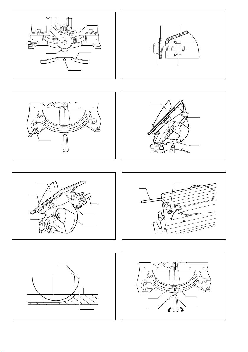
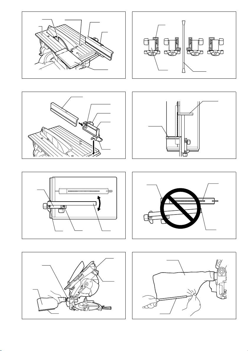
Installing auxiliary plate (Fig. 1 & 2)
the top blade guard moves smoothly up or down.
Install the auxiliary plate using the notch in the tool’s
If any of these blade guards becomes discolored through
base and secure it by tightening the hex bolt.
age or UV light exposure, contact a Makita service center
for a new guard. DO NOT DEFEAT OR REMOVE
Bench mounting (Fig. 3)
GUARDS.
This tool should be bolted with two bolts to a level and
stable surface using the bolt holes provided in the tool’s
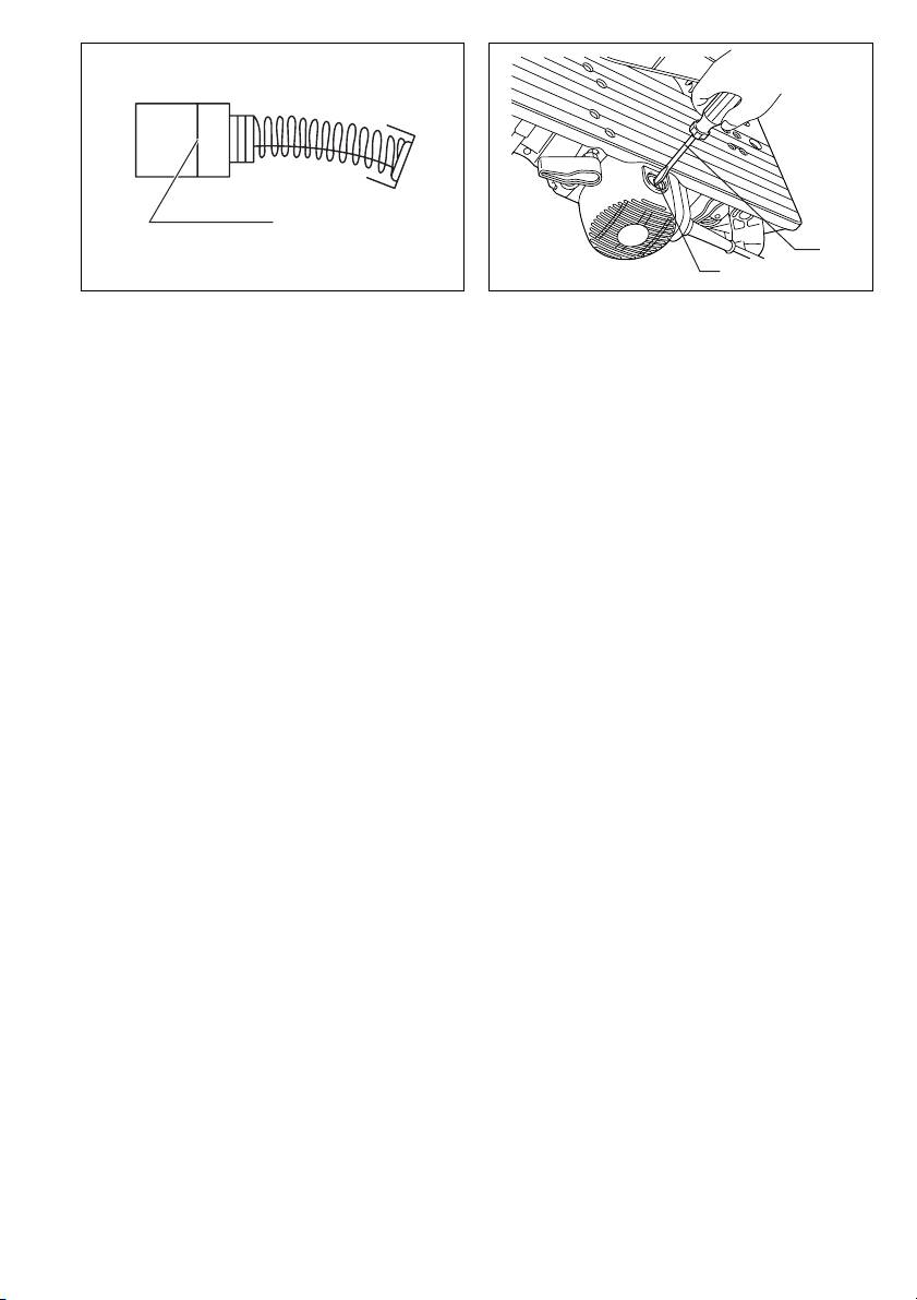
Maintaining maximum cutting capacity
base. This will help prevent tipping and possible injury.
(Fig. 6 & 7)
This tool is factory adjusted to provide the maximum cut-
ting capacity for a 260 mm saw blade.
FUNCTIONAL DESCRIPTION
When installing a new blade, always check the lower limit
CAUTION:
position of the blade and if necessary, adjust it as follows:
• Always be sure that the tool is switched off and
CAUTION:
unplugged before adjusting or checking function on the
• When making this adjustment, position the top table at
tool.
the lowest position after unplugging the tool.
Blade guard (Fig. 4 & 5)
First, unplug the tool. Position the top table at the lowest
CAUTION:
position. Lower the handle completely. Use the socket
• Make sure that the handle cannot be lowered without
wrench to turn the adjusting bolt that you can find below
pushing the lever nearby the handle to the left.
in the biggest hole in the top table, until the periphery of
• Make sure that the lower blade guards A and B dose
the blade extends slightly below the top surface of the
not open unless the lever near the handle is pushed at
turn base at the point where the front face of the guide
the topmost position of the handle.
fence meets the top surface of the turn base.
With the tool unplugged, rotate the blade by hand while
When lowering the handle while pushing the lever to the
holding the handle all the way down to be sure that the
left, the lower blade guard A rises automatically. The
blade does not contact any part of the lower base. Re-
lower blade guard B rises as it contacts a workpiece. The
adjust slightly, if necessary.
lower blade guards are spring loaded so it returns to its
original position when the cut is completed and the han-
CAUTION:
dle is raised. The top blade guard falls flat on the top sur-
• After installing a new blade, always be sure that the
face after workpiece has passed under it. NEVER
blade does not contact any part of the lower base when
DEFEAT OR REMOVE THE LOWER BLADE GUARDS,
the handle is lowered completely. Always do this with
THE SPRING WHICH ATTACHES TO THE LOWER
the tool unplugged.
BLADE GUARD, OR THE TOP BLADE GUARD.
14

Adjusting the miter angle (Fig. 8)
ASSEMBLY
Loosen the grip by turning counterclockwise. Turn the
CAUTION:
turn base while pressing down the lock lever. When you
• Always be sure that the tool is switched off and
have moved the grip to the position where the pointer
unplugged before carrying out any work on the tool.
points to the desired angle on the miter scale, securely
tighten the grip clockwise.
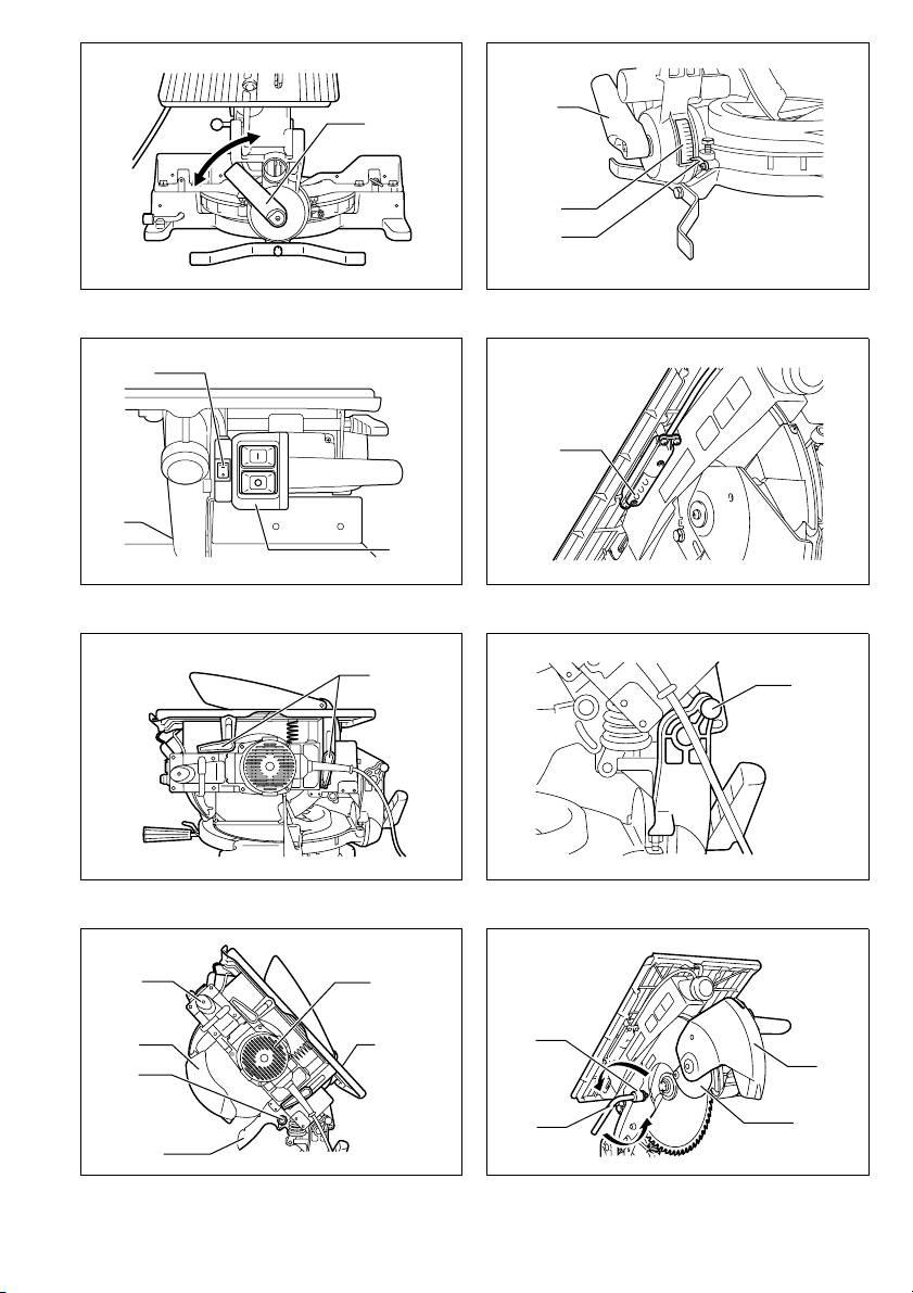
Installing or removing saw blade
CAUTION:
CAUTION:
• When turning the turn base, be sure to raise the handle
• Always be sure that the tool is switched off and
fully.
unplugged before installing or removing the blade.
• After changing the miter angle, always secure the turn
• Use only the Makita socket wrench provided to install
base by tightening the grip firmly.
or remove the blade. Failure to do so may result in
overtightening or insufficient tightening of the hex bolt.
Adjusting the bevel angle (Fig. 9 & 10)
This could cause an injury.
To adjust the bevel angle, loosen the lever at the rear of
the tool counterclockwise.
Secure the top table at the topmost position.
Push the handle to the left to tilt the saw blade until the
Lock the handle in the raised position by pushing in the
pointer points to the desired angle on the bevel scale.
stopper pin. (Fig. 14)
Then tighten the lever clockwise firmly to secure the arm.
To remove the blade, first loosen the clamping screw so
that the lower blade guard B is lowered as shown in the
CAUTION:
figure. (Fig. 15)
• When tilting the saw blade, be sure to raise the handle
Then use the socket wrench to loosen the hex bolt hold-
fully.
ing the center cover by turning it counterclockwise. Raise
• After changing the bevel angle, always secure the arm
the lower blade guard A and center cover while pushing
by tightening the lever clockwise.
the lever nearby the handle to the left. (Fig. 16)
Switch action (Fig. 11)
Press the shaft lock to lock the spindle and use the
socket wrench to loosen the hex bolt clockwise. Then
CAUTION:
remove the hex bolt, outer flange and blade. (Fig. 17)
• Before operation, make sure that the tool is turned on
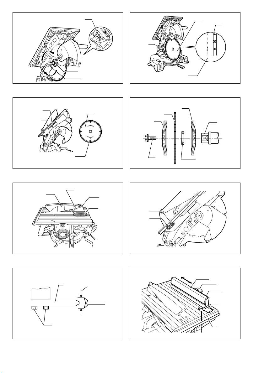
To install the blade, mount it carefully onto the spindle,
and off.
making sure that the direction of the arrow on the surface
To start the tool, press the ON ( I ) button. To stop it,
of the blade matches the direction of the arrow on the
press the OFF ( O ) button.
blade case. Install the outer flange and hex bolt, and then
use the socket wrench to tighten the hex bolt (left-
Lighting up the lamps (Fig. 11 & 12)
handed) securely counterclockwise while pressing the
For Model LH1040F only
shaft lock. (Fig. 18 & 19)
Push the upper position of the switch for turning on the
NOTE:
light and the lower position for off.
• When installing a saw blade, be sure to insert it from
CAUTION:
the outside of the blade guard B at first and then raise it
• Do not look in the light or see the source of light
so that the blade is finally placed in the blade guard B.
directly.
For all countries other than European countries
NOTE:
CAUTION:
• Use a dry cloth to wipe the dirt off the lens of lamp. Be
• The silver ring 25.4 mm in outer diameter is factory-
careful not to scratch the lens of light, or it may lower
installed onto the spindle. The black ring 25 mm in
the illumination.
outer diameter is included as standard equipment.
Adjusting the level of top table (Fig. 13)
Before mounting the blade onto the spindle, always be
To adjust the level of top table, loosen two levers by turn-
sure that the correct ring for the arbor hole of the blade
ing counterclockwise and then raise or lower the top
you intend to use is installed onto the spindle. (Fig. 20)
table. Tighten these levers firmly after the adjustment.
For European countries
WARNING:
CAUTION:
• Position the top table at the topmost position when
• The ring 30 mm in outer diameter is factory-installed
using the tool in the miter saw mode and at the desired
between the inner and outer flanges. (Fig. 20)
position when using in the table saw mode (bench
Return the lower blade guard A and center cover to its
mode).
original position. Then tighten the hex bolt clockwise to
secure the center cover. Raise the blade guard B as far
as it will go and tighten the clamping screw firmly while
holding it in the raised position. Lower the handle to
make sure that the lower blade guards move properly.
Make sure shaft lock has released spindle before making
cut.
15

Adjusting riving knife
To change from the pattern A or B to the pattern C or D,
Before adjusting the riving knife, loosen the two levers by
or in adverse case, remove the square nut, washer and
turning counterclockwise and press the top table on the
clamping screw (A) from the rip fence holder, then posi-
right side nearby the riving knife to its lowered position.
tion the clamping screw (A), washer and square nut on
Then secure the top table by firmly re-tightening the two
the opposite position of the rip fence holder compared to
levers as shown in the figure. (Fig. 21)
the original position. Tighten the clamping screw (A)
There must be a clearance of about 4 – 5 mm between
securely after inserting the square nut of the rip fence
the riving knife and the blade teeth. Adjust the riving knife
holder into the rip fence slit. Insert the square nut on the
accordingly by loosening two hex bolts counterclockwise
rip fence holder into the back end of either slit of the rip
with the hex socket wrench and measuring the distance.
fence so that they fit as shown in the figure. (Fig. 27)
Tighten the hex bolts securely, and then check to see that
The rip fence is factory adjusted so that it is parallel to
the top blade guard works smoothly before cutting.
the blade surface. Make sure that it is parallel. To check
(Fig. 22)
to be sure that the rip fence is parallel with the blade.
The riving knife has been installed before shipment from
Lower the table to the lowest position so that the blade
the factory so that the blade and riving knife are in a
appears at the topmost position from the table. Mark one
straight line. (Fig. 23)
of the blade teeth with a crayon. Measure the distance
(A) and (B) between the rip fence and blade. Take both
CAUTION:
measurements using the tooth marked with the crayon.
• If the blade and riving knife are not aligned properly, a
(Fig. 28) These two measurements should be identical. If
dangerous pinching condition may result during opera-
the rip fence is not parallel with the blade, proceed as fol-
tion. Make sure they are properly aligned. You could
lows: (Fig. 29)
suffer serious personal injury while using the tool with-
1. Turn two adjusting screws counterclockwise.
out a properly aligned riving knife. If they are not
aligned for any reasons, always have Makita authorized
2. Shift the back edge of the rip fence slightly to right or
service center repair it.
left until it becomes parallel with the blade.
3. Tighten the two screws on the rip fence firmly.
Installing and adjusting rip fence
CAUTION:
1. Install the rip fence on the table so that the rip fence
• Be sure to adjust the rip fence so that it is parallel with
holder engages with the guide rail. Tighten the
the blade, or a dangerous kickback condition may
clamping screw (B) of the rip fence firmly clockwise.
occur.
2. Loosen the clamping screw (A).
• Be sure to adjust the rip fence so that it does not con-
3. Slide the rip fence and secure it so that the far end
tact the top blade guard or saw blade. (Fig. 30)
from you of the rip fence is aligned with the point at
which the front edge of saw blade just appears from
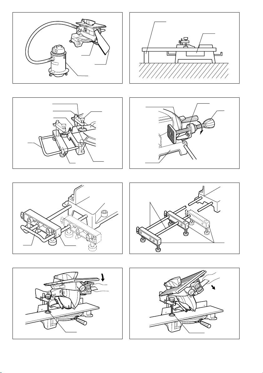
Dust bag
top surface of the workpiece. The purpose of this
The use of the dust bag makes cutting operations clean
adjustment is to reduce risk of kick-back toward
and dust collection easy. To attach the dust bag, fit it onto
operator that cut piece from the workpiece is
the dust nozzle. (Fig. 31)
pinched between the saw blade and rip fence and
NOTE:
finally pushed out toward operator. The line 3 varies
• In miter saw mode, always insert the dust bag to the
by thickness of workpiece or the table level. Adjust
back nozzle only.
the position of the rip fence according to the thick-
When the dust bag is about half full, remove the dust bag
ness of the workpiece.
from the tool and pull the fastener out. Empty the dust
After adjusting the rip fence, tighten the clamping
bag of its contents, tapping it lightly so as to remove par-
screw (A) firmly. (Fig. 24 & 25)
ticles adhering to the insides which might hamper further
NOTE:
collection. (Fig. 32)
• There are four patterns to position the rip fence as
If you connect a vacuum cleaner to your saw, more effi-
shown in the figure. (Fig. 26) Rip fence has two slits on
cient and cleaner operations can be performed.
its sides, one slit with an elevated fringe nearby on the
To install the blade cover when using in the table saw
same side and the other without it. Use the surface of
mode (bench mode), turn the turn base to 0° miter angle
rip fence with this fringe facing the workpiece only
(see the section titled “Adjusting miter angle”) and place
when cutting off into a piece of a thin workpiece.
the blade cover on the turn table so that the blade cover
• To change the rip fence pattern, remove the rip fence
is centered over the slit for the blade entrance in the turn
from the rip fence holder by loosening the clamping
table and then lock the handle in the lowest position by
screw (A) and change the facing of the rip fence to the
fully pushing in the stopper pin as shown in the figure.
rip fence holder so that the rip fence faces the rip fence
(Fig. 33)
holder according to your work as shown in the figure.
NOTE:
Insert the square nut on the rip fence holder into the
• To attach the dust bag to the front dust nozzle in the
back end of either slit of the rip fence so that they fit as
table saw mode (bench mode), first remove the cap
shown in the figure.
from the front dust nozzle and then attach the dust bag
to the dust nozzle.
• When not in use of dust bag, always replace the cap to
the front dust nozzle. Failure to do so result in dust
scattering from the nozzle.
• When using the tool in the table saw mode (bench
mode), make sure that the blade cover is installed on
the turn table.
16

Securing workpiece
Holders and holder assembly
Whenever possible, secure the workpiece with the
(optional accessories)
optional vise. If you must use your hand to hold the work-
The holders and the holder assembly can be installed on
piece, then it must be done firmly and securely so as not
either side as a convenient means of supporting work-
to lose control of the workpiece. Your hand and arm must
pieces horizontally. Install them as shown in the figure.
be kept well away from the blade area (100 mm mini-
Then tighten the screws firmly to secure the holders and
mum). Squeeze the workpiece firmly against the guide
the holder assembly. (Fig. 37)
fence with your fingers held over the top of the guide
When cutting long workpieces, use the holder-rod
fence. The workpiece must also rest steadily on the turn
assembly (optional accessory). It consists of two holder
base.
assemblies and two rods 12. (Fig. 38)
WARNING:
CAUTION:
• Never use your hand to hold the workpiece that
• Always support long workpieces level with the top sur-
requires your hand to be any closer than 100 mm from
face of the turn base for accurate cuts and to prevent
the blade area. In this case, always use the optional
dangerous loss of control of the tool.
vise to secure the workpiece. After any cutting opera-
tion, raise the blade gently. Never raise the blade until it
OPERATION
has come to a complete stop. Serious injury may result.
CAUTION:
CAUTION:
• Before use, be sure to release the handle from the low-
• When cutting long workpieces, use supports that are
ered position by pulling the stopper pin.
as high as the top surface level of the turn base. Do not
• Make sure the blade is not contacting the workpiece,
rely solely on the vertical vise and/or horizontal vise
etc. before the switch is turned on.
(both optional) to secure the workpiece. (Fig. 34)
Thin material tends to sag. Support workpiece over its
CUTTING AS MITER SAW
entire length to avoid blade pinch and possible KICK-
WARNING:
BACK.
• When using the tool in the miter saw mode, secure the
top table at the topmost position so that the saw blade
Vertical vise (optional accessory) (Fig. 35)
never protrudes from the top surface of the top table.
The vertical vise can be installed in two positions on
either the left or right side of the guide fence or the holder
CAUTION:
assembly (optional accessory). Insert the vise rod into
• Do not apply excessive pressure on the handle when
the hole in the guide fence or the holder assembly and
cutting. Too much force may result in overload of the
tighten the screw to secure the vise rod.
motor and/or decreased cutting efficiency. Push down
Position the vise arm according to the thickness and
handle with only as much force as is necessary for
shape of the workpiece and secure the vise arm by tight-
smooth cutting and without significant decrease in
ening the screw. If the screw to secure the vise arm con-
blade speed.
tacts the guide fence, install the screw on the opposite
• Gently press down the handle to perform the cut. If the
side of vise arm. Make sure that no part of the tool con-
handle is pressed down with force or if lateral force is
tacts the vise when lowering the handle all the way. If
applied, the blade will vibrate and leave a mark (saw
some part contacts the vise, re-position the vise.
mark) in the workpiece and the precision of the cut will
Press the workpiece flat against the guide fence and the
be impaired.
turn base. Position the workpiece at the desired cutting
1. Press cutting (Fig. 39)
position and secure it firmly by tightening the vise knob.
Secure the workpiece against guide fence and turn table.
CAUTION:
Switch on the tool without the blade making any contact
• The workpiece must be secured firmly against the turn
and wait until the blade attains full speed before lowering.
base and guide fence.
Then gently lower the handle to the fully lowered position
to cut the workpiece. When the cut is completed, switch
Horizontal vise (optional accessory) (Fig. 36)
off the tool and WAIT UNTIL THE BLADE HAS COME
The horizontal vise can be installed on either the left or
TO A COMPLETE STOP before returning the blade to its
right side of the base. When performing 15° or greater
fully elevated position.
miter cuts, install the horizontal vise on the side opposite
the direction in which the turn base is to be turned. By
2. Miter cutting
turning the vise knob counterclockwise, the screw is
Refer to the previously covered “Adjusting the miter
released and the vise shaft can be moved rapidly in and
angle”.
out. By turning the vise knob clockwise, the screw
3. Bevel cut (Fig. 40)
remains secured. To grip the workpiece, turn the vise
Loosen the lever and tilt the saw blade to set the bevel
knob gently clockwise until the projection reaches its top-
angle (Refer to the previously covered “Adjusting the
most position, then fasten securely. If the vise knob is
bevel angle”). Be sure to retighten the lever firmly to
forced in or pulled out while being turned clockwise, the
secure the selected bevel angle safely. Secure the work-
projection may stop at an angle. In this case, turn the
piece against guide fence and turn table. Make sure the
vise knob back counterclockwise until the screw is
carriage is pulled all the way back toward the operator.
released, before turning again gently clockwise.
Switch on the tool without the blade making any contact
The maximum width of the workpiece which can be
and wait until the blade attains full speed. Then gently
secured by the horizontal vise is 130 mm.
lower the handle to the fully lowered position while apply-
ing pressure in parallel with the blade. When the cut is
completed, switch off the tool and WAIT UNTIL THE
BLADE HAS COME TO A COMPLETE STOP before
returning the blade to its fully elevated position.
17
CAUTION:
4. Compound cutting
• Always be sure that the blade will move down to bevel
Compound cutting is the process in which a bevel angle
direction during a bevel cut. Keep hands out of path of
is made at the same time in which a miter angle is being
saw blade.
cut on a workpiece. Compound cutting can be performed
• During a bevel cut, it may create a condition whereby
at angle shown in the table.
the piece cut off will come to rest against the side of the
Bevel angle Miter angle
blade. If the blade is raised while the blade is still rotat-
ing, this piece may be caught by the blade, causing
45° Left and Right 0° – 45°
fragments to be scattered which is dangerous. The
blade should be raised ONLY after the blade has come
When performing compound cutting, refer to “Press cut-
to a complete stop.
ting”, “Miter cutting” and “Bevel cut” explanations.
• When pressing the handle down, apply pressure paral-
5. Cutting aluminum extrusion (Fig. 41)
lel to the blade. If the pressure is not parallel to the
When securing aluminum extrusions, use spacer blocks
blade during a cut, the angle of the blade might be
or pieces of scrap as shown in the figure to prevent defor-
shifted and the precision of the cut will be impaired.
mation of the aluminum. Use a cutting lubricant when
cutting the aluminum extrusion to prevent buildup of the
aluminum material on the blade.
CAUTION:
• Never attempt to cut thick or round aluminum extru-
sions. Thick aluminum extrusions may come loose dur-
ing operation and round aluminum extrusions cannot
be secured firmly with this tool.
• Never cut aluminum in the table saw mode (bench
mode).
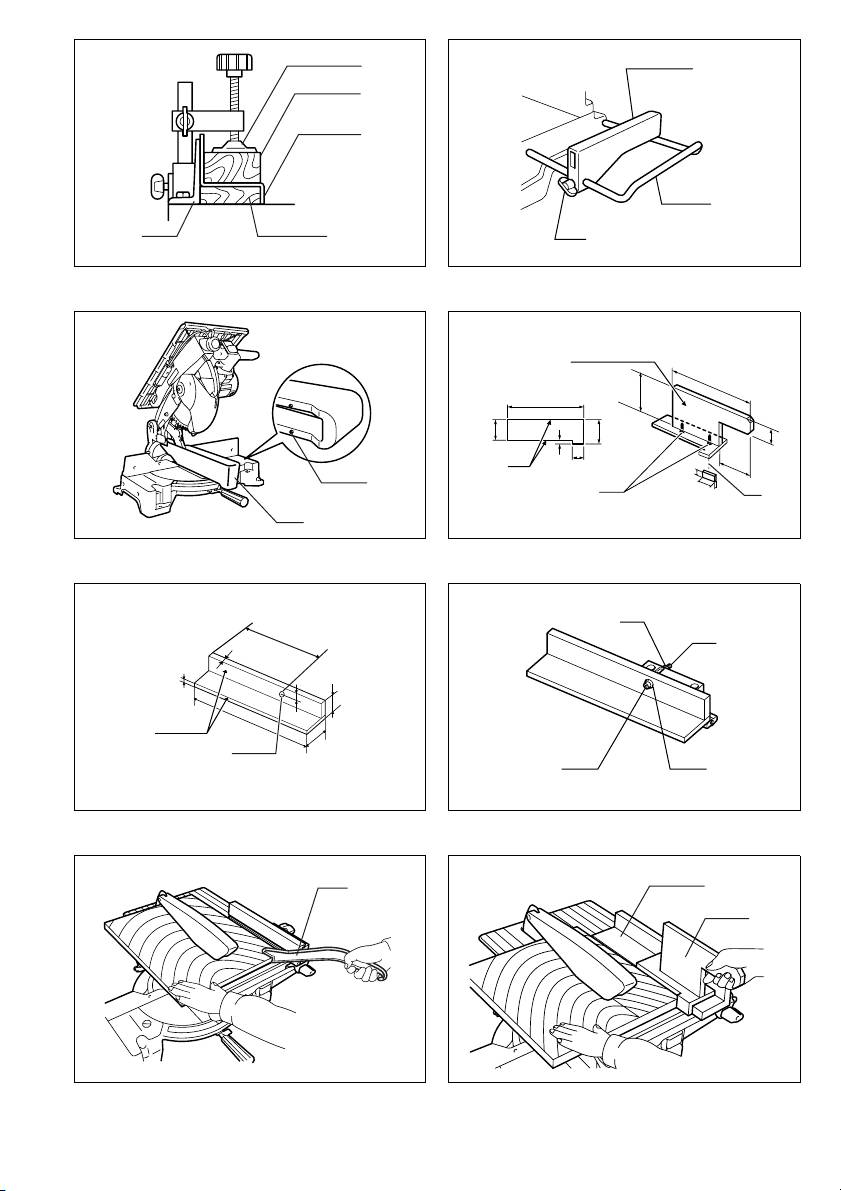
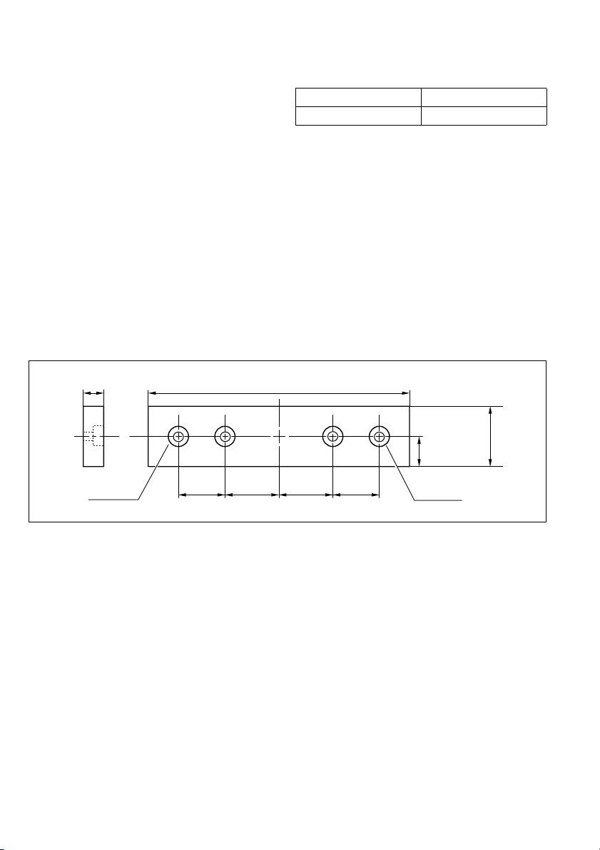
6. Wood facing
Use of wood facing helps to assure splinter-free cuts in workpieces. Attach a wood facing to the guide fence using the
holes in the guide fence.
See the figure concerning the dimensions for a suggested wood facing.
Over 460 mmOver 10 mm
90 mm
25 mm
Hole
Hole
90 mm 107 mm 107 mm 90 mm
CAUTION:
• Use straight wood of even thickness as the wood facing.
• Use screws to attach the wood facing to the guide fence. The screws should be installed so that the screw heads are
below the surface of the wood facing.
• When the wood facing is attached, do not turn the turn base with the handle lowered. The blade and/or the wood fac-
ing will be damaged.
7. Cutting repetitive lengths (Fig. 42)
When cutting several pieces of stock to the same length,
ranging from 240 mm to 400 mm, use of the set plate will
facilitate more efficient operation. Install the set plate on
the holder as shown in the figure.
Align the cutting line on your workpiece with either the
left or right side of the groove in the kerf board, and while
holding the workpiece from moving, move the set plate
flush against the end of the workpiece. Then secure the
set plate with the screw. When the set plate is not used,
loosen the screw and turn the set plate out of the way.
NOTE:
• Use of the holder-rod assembly (optional accessory)
allows cutting repetitive lengths up to 2,200 mm
approximately.
18

CUTTING AS TABLE SAW (BENCH MODE)
(2) When the width of rip is narrower than 40 mm,
the push stick cannot be used because the
CAUTION:
push stick will strike the top blade guard. Use
• When using the tool in the table saw mode (bench
the auxiliary fence and push block.
mode), place the blade cover on the turn table so that
Install securely the auxiliary fence which is
the blade cover is centered over the slit for the blade
secured to the rip fence holder on the table.
entrance in the turn table and two small bosses on the
Feed the workpiece by hand until the end is
underside of the blade cover fit into the semi-circular
about 25 mm from the front edge of the top
slit in the periphery of the turn table as shown in the fig-
table. Continue to feed using the push block on
ure and then lock the handle in the lowest position by
the top of the auxiliary fence until the cut is
fully pushing in the stopper pin. (Fig. 43)
complete. (Fig. 48)
• Always use “work helpers” such as push sticks and
push blocks when there is a danger that your hands or
Carrying tool
fingers will come close to the blade.
Make sure that the tool is unplugged. Secure the blade at
• NEVER withdraw the workpiece while the blade is run-
0° bevel angle and the turn base at left miter angle fully.
ning. If you must withdraw the workpiece before com-
Lower the handle fully and lock it in the lowered position
pleting a cut, first switch the tool off while holding the
by fully pushing in the stopper pin. (Fig. 49)
workpiece firmly. Wait until the blade has come to a
Carry the tool by holding both sides of the tool base as
complete stop before withdrawing the workpiece. Fail-
shown in the figure. If you remove the holders, dust bag,
ure to do so may cause dangerous kickbacks.
etc., you can carry the tool more easily. (Fig. 50)
• NEVER remove cut-off material while the blade is run-
CAUTION:
ning.
• Always secure all moving portions before carrying the
• NEVER place your hands or fingers in the path of the
tool.
saw blade.
• Always secure the rip fence firmly, or dangerous kick-
backs may occur.
MAINTENANCE
CAUTION:
Work helpers
• Always be sure that the tool is switched off and
Push sticks, push blocks or auxiliary fence are types of
unplugged before attempting to perform inspection or
“work helpers”. Use them to make safe, sure cuts without
maintenance.
the need for the operator to contact the blade with any
part of the body.
WARNING:
• Always be sure that the blade is sharp and clean for the
Push block (Fig. 44)
best and safest performance.
Use a 15 mm piece of plywood.
Handle should be in center of plywood piece. Fasten with
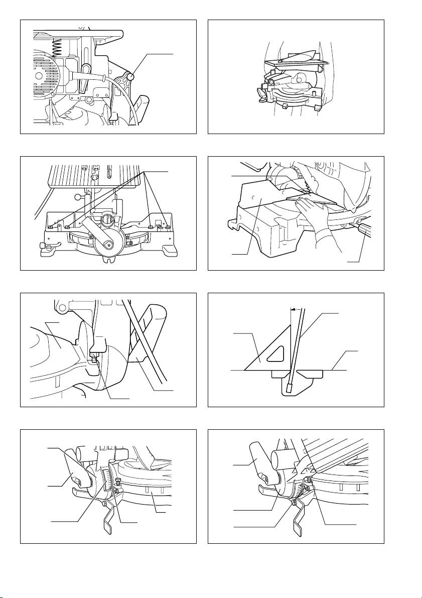
Adjusting the cutting angle
glue and wood screws as shown. Small piece 10 mm x
This tool is carefully adjusted and aligned at the factory,
9 mm x 30 mm of wood must always be glued to plywood
but rough handling may have affected the alignment. If
to keep the blade from dulling if the operator cuts into
your tool is not aligned properly, perform the following:
push block by mistake. (Never use nails in push block.)
1. Miter angle
Loosen the grip which secures the turn base. Turn the
Auxiliary fence (Fig. 45 & 46)
turn base so that the pointer points to 0° on the miter
Make auxiliary fence from 10 mm and 15 mm plywood
scale. Tighten the grip and loosen the hex bolts securing
pieces.
the guide fence using the socket wrench. (Fig. 51)
Remove the rip fence, clamping screw (A), flat washer
Lower the handle fully and lock it in the lowered position
and square nut from the rip fence holder and then attach
by pushing in the stopper pin. Square the side of the
and secure the auxiliary fence to the rip fence holder by
blade with the face of the guide fence using a triangular
using a bolt M6 longer than M6 x 50, washers and nut.
rule, try-square, etc. Then securely tighten the hex bolts
Ripping
on the guide fence in the order from the right side.
(Fig. 52)
CAUTION:
• When cutting long or large workpieces, always provide
2. Bevel angle
adequate support behind the table. DO NOT allow a
(1) 0° bevel angle
long board to move or shift on the table. This will cause
Lower the handle fully and lock it in the lowered posi-
the blade to bind and increase the possibility of kick-
tion by pushing in the stopper pin. Loosen the lever
back and personal injury. The support should be at the
at the rear of the tool. Turn the 0° bevel angle adjust-
same height as the table.
ing bolt on the right side of the turn base two or three
1. Adjust the depth of cut a bit higher than the thick-
revolutions clockwise to tilt the blade to the right.
ness of the workpiece. To make this adjustment,
(Fig. 53)
loosen two levers and lower or raise the top table.
Carefully square the side of the blade with the top
2. Position the rip fence to the desired width of rip and
surface of the turn base using the triangular rule, try-
secure in place by tightening the clamping screw
square, etc. by turning the 0° bevel angle adjusting
(A). Before ripping, make sure the two screws of the
bolt counterclockwise. (Fig. 54)
rip fence holder are secured. If it is not secured
Make sure that the pointer on the turn base point to
enough, retighten it.
0° on the bevel scale on the arm. If it does not point
to 0°, loosen the screw which secures the pointer
3. Turn the tool on and gently feed the workpiece into
and adjust the pointer so that it will point to 0°.
the blade along with the rip fence.
(Fig. 55)
(1) When the width of rip is 40 mm or wider, use a
push stick. (Fig. 47)
19

(2) 45° bevel angle
Noise and Vibration
Adjust the 45° bevel angle only after performing 0°
ENG005-1
bevel angle adjustment. To adjust left 45° bevel
The typical A-weighted noise levels are
angle, loosen the lever and tilt the blade to the left
sound pressure level: 92 dB (A)
fully. Make sure that the pointer on the arm points to
sound power level: 105 dB (A)
45° on the bevel scale on the arm. If the pointer
– Wear ear protection. –
does not point to 45°, turn the 45° bevel angle
The typical weighted root mean square acceleration
2
adjusting bolt on the left side of the arm until the
value is not more than 2.5 m/s
.
pointer points to 45°. (Fig. 56)
Replacing carbon brushes (Fig. 57 & 58)
EC-DECLARATION OF CONFORMITY
Remove and check the carbon brushes regularly.
ENH003-1
Replace when they wear down to the limit mark. Keep
We declare under our sole responsibility that this product is
the carbon brushes clean and free to slip in the holders.
in compliance with the following standards of standardized
Both carbon brushes should be replaced at the same
documents,
time. Use only identical carbon brushes.
EN61029, EN55014, EN61000
Use a screwdriver to remove the brush holder caps. Take
in accordance with Council Directives, 73/23/EEC,
out the worn carbon brushes, insert the new ones and
89/336/EEC and 98/37/EC.
secure the brush holder caps.
Certificate of adequacy of the technical file with respect
to 98/37/EC having been obtained from the following
After use
notified body:
• After use, wipe off chips and dust adhering to the tool
Intertek SEMKO AB, Torshamnsgatan 43, Box 1103,
with a cloth or the like. Keep the blade guard clean
SE-164 22 Kista, Sweden
according to the directions in the previously covered
Yasuhiko Kanzaki
CE2004
section titled “Blade guard”. Lubricate the sliding por-
tions with tool oil to prevent rust.
To maintain product SAFETY and RELIABILITY, repairs,
any other maintenance or adjustment should be per-
Director
formed by Makita Authorized Service Centers, always
using Makita replacement parts.
MAKITA INTERNATIONAL EUROPE LTD.
Michigan Drive, Tongwell, Milton Keynes,
ACCESSORIES
Bucks MK15 8JD, ENGLAND
CAUTION:
• These accessories or attachments are recommended
for use with your Makita tool specified in this manual.
The use of any other accessories or attachments might
present a risk of injury to persons. Only use accessory
or attachment for its stated purpose.
If you need any assistance for more details regarding
these accessories, ask your local Makita service center.
• Steel & Carbide-tipped saw blades
• Auxiliary plate
• Vise assembly (Horizontal vise)
• Vertical vise
• Socket wrench 13
• Holder set
• Holder assembly
• Holder rod assembly
• Set plate
• Dust bag
• Triangular rule
• Blade cover (Blade guard C)
• Push stick
• Ruler assembly (Rip fence)
20
