Kenwood KDC-W427: Connecting Wires to Terminals
Connecting Wires to Terminals: Kenwood KDC-W427
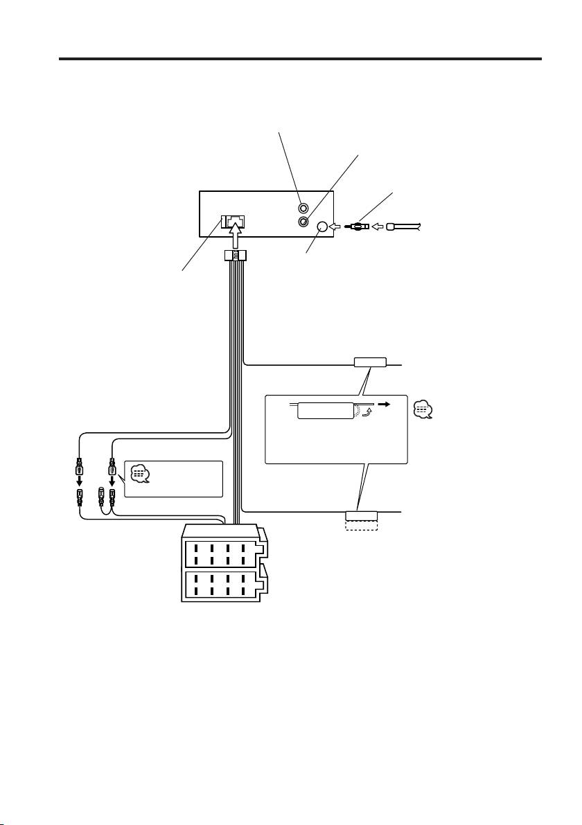
Connecting Wires to Terminals
Rear left output (White)
Rear right output (Red)
Antenna Conversion Adaptor (ISO–
JASO) (Accessory3)
REAR
L
R
Antenna Cord (ISO)
FM/AM antenna
input
Fuse (10A)
Wiring harness
(Accessory1)
Connect to the terminal that
TEL mute wire (Brown)
TEL MUTE
is grounded when either the
telephone rings or during
conversation.
To connect the KENWOOD
navigation system, consult
Battery wire (Yellow)
your navigation manual.
If no connections are made, do
Ignition wire (Red)
not let the wire come out from
the tab.
See next page
Power control/ Motor
antenna control wire
Connect either to the power
A –7 Pin (Red)
(Blue/White)
control terminal when using the
P.CONT
optional power amplifier, or to
ANT.CONT
A–4 Pin (Yellow)
the antenna control terminal in
the vehicle.
8
6
4
2
Connector A
7
5
3
1
Connector B
8
6
4
2
7
5
3
1
22
|
English
B64-2807-00U.S.Inddtcsp22 03.12.11,6:27:30PM
Connecting Wires to Terminals
Connector Function Guide
2WARNING
Pin Numbers for
Cable Colour Functions
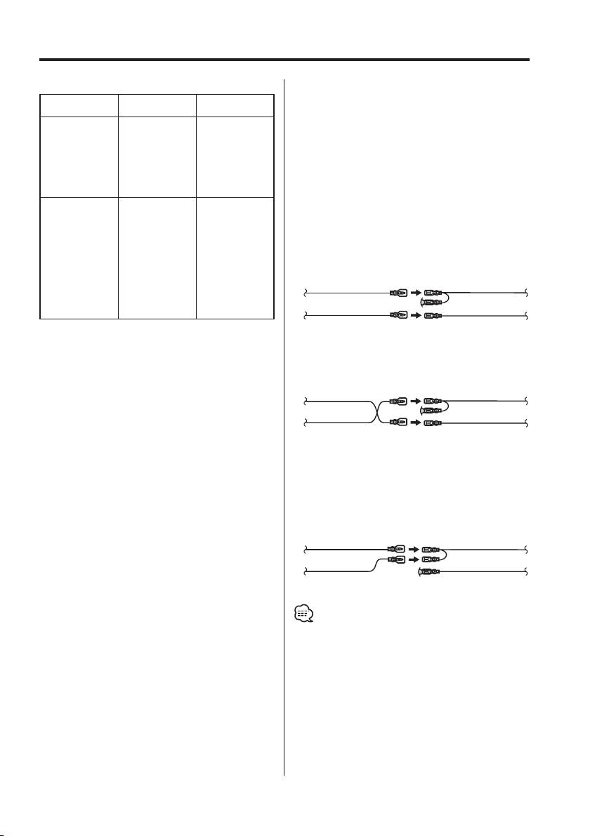
Connecting the ISO Connector
ISO Connectors
The pin arrangement for the ISO connectors depends
External Power
on the type of vehicle you drive. Make sure to make the
Connector
proper connections to prevent damage to the unit.
A-4 Yellow Battery
The default connection for the wiring harness is described
A-5 Blue/White Power Control
in 1 below. If the ISO connector pins are set as described
A-7 Red Ignition (ACC)
A-8 Black Earth (Ground)
in 2 or 3, make the connection as illustrated.
Connection
Please be sure to reconnect the cable as shown 2 below
Speaker
to install this unit to the Volkswagen vehicles etc.
Connector
B-1 Purple Rear Right (+)
1 (Default setting) The A-7 pin (red) of the vehicle’s
B-2 Purple/Black Rear Right (–)
ISO connector is linked with the ignition, and
B-3 Gray Front Right (+)
the A-4 pin (yellow) is connected to the constant
B-4 Gray/Black Front Right (–)
power supply.
B-5 White Front Left (+)
Ignition cable (Red)
A-7 Pin (Red)
B-6 White/Black Front Left (–)
B-7 Green Rear Left (+)
Unit Vehicle
B-8 Green/Black Rear Left (–)
Battery cable (Yellow)
A-4 Pin (Yellow)
2 The A-7 pin (red) of the vehicle’s ISO connector
is connected to the constant power supply, and
the A-4 pin (yellow) is linked to the ignition.
Ignition cable
(Red)
A-7 Pin (Red)
Unit Vehicle
Battery cable
A-4 Pin (Yellow)
(Yellow)
3 The A-4 pin (yellow) of the vehicle’s ISO
connector is not connected to anything, while
the A-7 pin (red) is connected to the constant
power supply (or both the A-7 (red) and A-4
(yellow) pins are connected to the constant
power supply).
Ignition cable (Red)
A-7 Pin (Red)
Unit Vehicle
Battery cable (Yellow)
A-4 Pin (Yellow)
• When the connection is made as in 3 above, the unit’s
power will not be linked to the ignition key. For that
reason, always make sure to turn off the unit’s power
when the ignition is turned off.
To link the unit’s power to the ignition, connect the
ignition cable (ACC...red) to a power source that can be
turned on and off with the ignition key.
English
|
23
B64-2807-00U.S.Inddtcsp23 03.12.11,6:27:31PM
Table of contents
- Contents
- Safety precautions
- Notes
- Notes on playing MP3/WMA
- About CDs
- General features
- Tuner features
- CD/MP3/WMA control features
- Menu system
- Accessories/ Installation Procedure
- Connecting Wires to Terminals
- Installation
- Removing the Unit
- Troubleshooting Guide
- Specifications
- Cодержание
- Меры предосторожности
- Примечания
- Примечания к проигрыванию MP3/WMA
- О CD
- Общие характеристики
- Функции тюнера
- Функции управления CD/MP3/WMA
- Система меню
- Принадлежности/ Процесс установки
- Подсоединение кабелей к гнездам для подключения
- Установка
- Cнятие аппарата
- Поиск и устранение неисправностей
- Технические характеристики
- Treść
- Środki ostrożności
- Uwagi
- Uwagi o odtwarzaniu MP3/WMA
- Uwagi dotyczące płyt kompaktowych
- Ogólne możliwości
- Możliwości tunera
- Możliwości sterowania CD/MP3/WMA
- Menu systemu
- Akcesoria/ Procedura instalowania
- Podłączanie przewodów do końcówek
- Instalacja
- Wyjmowanie aparatu
- Przewodnik wykrywania i usuwania usterek
- Dane techniczne
