Ingersoll-Rand 1103: instruction
Class: Tools, power tools and power equipment
Type:
Manual for Ingersoll-Rand 1103
04585022
Edition 2
June 2006
Air Ratchet Wrench
1103 and 1133
Product Information
EN
Product Information
SL
Specifikacije izdelka
ES
Especificaciones del producto
SK
Špecifikácie produktu
FR
Spécifications du produit
CS
Specifikace výrobku
IT
Specifiche prodotto
ET
Toote spetsifikatsioon
DE
Technische Produktdaten
HU
A termék jellemzői
NL
Productspecificaties
LT
Gaminio techniniai duomenys
DA
Produktspecifikationer
LV
Ierices specifikacijas
SV
Produktspecifikationer
PL
Dane techniczne narzędzia
NO
Produktspesifikasjoner
Rozmiar
FI
Tuote-erittely
RU
Технические характеристики
PT
Especificações do Produto
изделия
EL
Προδιαγραφές προϊόντος
ZH
产品信息
Save These Instructions
9
3
2
10
30d
48h
12
1
6m
PMAX
4
8
24h
7
11
3m
5
6
(Dwg. 16571804-2)
9
1
2
3
5
6
7
10
11
12
I-R #-
inch
3
3
3
I-R #-BS
NPT I-R # I-R # I-R #
cm
I-R #
cm
I-R #
cm
NPT
(mm)
C241-
C28241-
3/8 (10) 1/4 MSCF33 10 66 1 66 2 28 1
810
810-B
2 04585022_ed2

EN
Product Safety Information
Intended Use:
These Air Ratchet Wrenches are designed to remove and install threaded fasteners.
For additional information refer to Air Ratchet Wrenches Product Safety Information
Manual Form 04580361.
Manuals can be downloaded from www.irtools.com.
Power Management System
The power management system allows operator reduction of maximum output power in
either the forward or the reverse direction.
To adjust the power, rotate the Power Regulator to the desired level indicator.
The power level indicators are for reference and do not indicate a specific power. The
power output can be further reduced in forward or reverse by using the variable throttle.
Product Specifications
Vibration
Free
Recommended
Sound Level dB (A)
Drive
Level
Speed
Torque Range
(ISO15744)
(ISO8662)
Model(s)
† Pressure
Size rpm ft-lb (Nm)
‡ Power (L
)
w
m/s²
(L
)
p
1103 1/4” 270 5-23 (7-31) 86.6 97.6 4.6
1133 3/8” 270 5-25 (7-34) 86.6 97.6 4.6
† K
= 3dB measurement uncertanity
pA
‡ K
= 3dB measurement uncertanity
wA
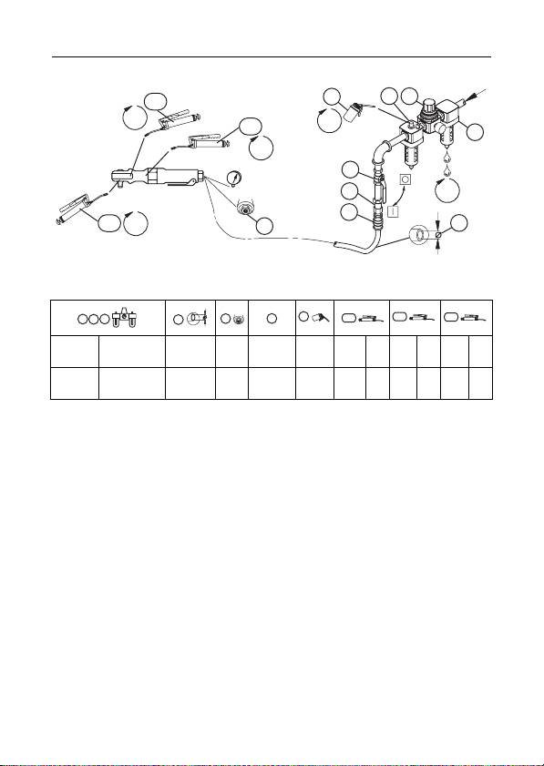
Installation and Lubrication
Size air supply line to ensure tool's maximum operating pressure (PMAX) at tool inlet.
Drain condensate from valve(s) at low point(s) of piping, air filter and compressor tank daily.
Install a properly sized Safety Air Fuse upstream of hose and use an anti-whip device
across any hose coupling without internal shut-off, to prevent hose whipping if a hose fails
or coupling disconnects. See drawing 16571804-2 and table on page 2.
Maintenance frequency is shown in circular arrow and defined as h=hours, d=days, and
m=months. Items identified as:
1. Air filter 8. Safety Air Fuse
2. Regulator 9. Oil
3. Lubricator 10. Grease - Inject between ratchet housing and yoke
4. Emergency shut-off valve to lubricate drive bushing.
5. Hose diameter 11. Grease - Disassemble ratchet head and lubricate
6. Thread size components.
7. Coupling 12. Grease - Disassemble gearing and lubricate
components.
04585022_ed2 EN-1
