MEDC SM87 LU1: инструкция
Раздел: Системы безопасности
Тип: Датчик
Инструкция к Датчику MEDC SM87 LU1

Technical Manual for the steady beacons - SM87LU1 & SM87LU3
Техническое руководство к обращению с непрерывно
действующими маячками — SM87LU1 и SM87LU3
Manuel technique pour les balises statiques - SM87LU1 & SM87LU3
Technische Anleitung für die Dauerleuchten SM87LU1 & SM87LU3
Manual técnico de las balizas fijas SM87LU1 y SM87LU3
Please note that every care has been taken to ensure the accuracy of our technical manual. We do not, however,
accept responsibility for damage, loss or expense resulting from any error or omission. We reserve the right to
make alterations in line with technical advances and industry standards.
Для обеспечения максимальной точности нашего технического руководства были предприняты
все возможные меры. Наша компания не несет ответственности за повреждения, ущерб или
расходы, связанные с возможным наличием в нем ошибок или пропусков. Мы оставляем
за собой право вносить в него изменения с учетом технического прогресса и изменения
промышленных стандартов.
Toutes les précautions ont été prises pour garantir la précision de cette notice technique. Toutefois, nous ne saurions
accepter de responsabilité à l’égard des dégâts, pertes ou frais résultant d’une quelconque erreur ou omission.
Nous nous réservons le droit d’apporter d’éventuelles modifications pouvant résulter de progrès techniques ou
de l’évolution des normes industrielles.
Wir möchten Sie darauf hinweisen, dass wir große Sorgfalt darauf verwendet haben, die Richtigkeit unserer
technischen Anleitung zu gewährleisten. Wir übernehmen jedoch keine Verantwortung für Schäden, Verluste
oder Kosten, die sich aus einem etwaigen Fehler oder einer Auslassung ergeben. Mit dem technischen Fortschritt
und Industrienormen einhergehende Änderungen behalten wir uns vor.
Observe que todos os cuidados foram tomados para assegurar a exatidão de nosso manual técnico. No entanto, não
nos responsabilizamos por danos, perdas ou despesas resultantes de qualquer erro ou omissão. Reservamo-nos o direito
de efetuar alterações em linha com os avanços tecnológicos e as normas da indústria.
© Cooper MEDC 2010 11/10

English
1.0 INTRODUCTION
These steady beacons have been designed for use in flammable atmospheres and harsh environmental conditions.
The marine grade alloy or stainless steel enclosures are suitable for use offshore or onshore, where light weight
combined with corrosion resistance and strength is required.
2.0 INSTALLATION
General
When installing and operating explosion-protected equipment, requirements for selection, installation and
operation should be referred to e.g. IEE Wiring Regulations and the ‘National Electrical Code’ in North America.
Additional national and/or local requirements may apply.
Ensure that all nuts, bolts and fixings are secure.
Ensure that only the correct listed or certified stopping plugs are used to blank off unused gland entry points
and that the NEMA/IP rating of the unit is maintained.
The beacon is mounted via the 4 off Ø9mm fixing holes in the base of the unit. The fixing holes have been
designed to accept an M8 screw or bolt.
MEDC recommend the use of stainless steel screws.
The unit has been designed and certified to operate at any attitude
Cable Termination
CAUTION: Before removing the cover assembly, ensure that the power to the unit is isolated and gas and/
or dust atmospheres are not present.
Unscrew the 4 off screws (5mm A/F hexagon key) holding the cover assembly to the base. Keep screws in a
safe accessible place as they are not retained in the cover.
Gently twist the cover clockwise and anti-clockwise whilst pulling it away from the base of the enclosure to gain
access to the interior.
Cable termination should be in accordance with specifications applying to the required application. MEDC
recommends that all cables and cores should be correctly identified. Please refer to the wiring diagram provided
with the product.
Ensure that only the correct listed or certified cable glands are used and that the assembly is shrouded and
correctly earthed.
All cable glands should be of an equivalent NEMA/IP rating to that of the beacon and integrated with the unit
such that this rating is maintained.
The internal earth terminal, where fitted, must be used for the equipment grounding connection and the external
terminal is for a supplementary bonding connection where local codes or authorities permit or require such a
connection.
Once termination is complete, carefully lower the cover assembly back onto the base, avoiding damage to
the mating surfaces. Ensure the o-ring is correctly seated in its groove during re-assembly. Replace and evenly
tighten the 4 off cover screws. Ensure the required gap (0.15mm max.) is maintained between the cover and
the base.
3.0 OPERATION
The operating voltage of the unit is stated on the certification label. The beacon can be initiated either directly
or remotely depending on the type ordered. Please see the wiring documentation supplied with the unit for
further information.
11/10 © Cooper MEDC 2010
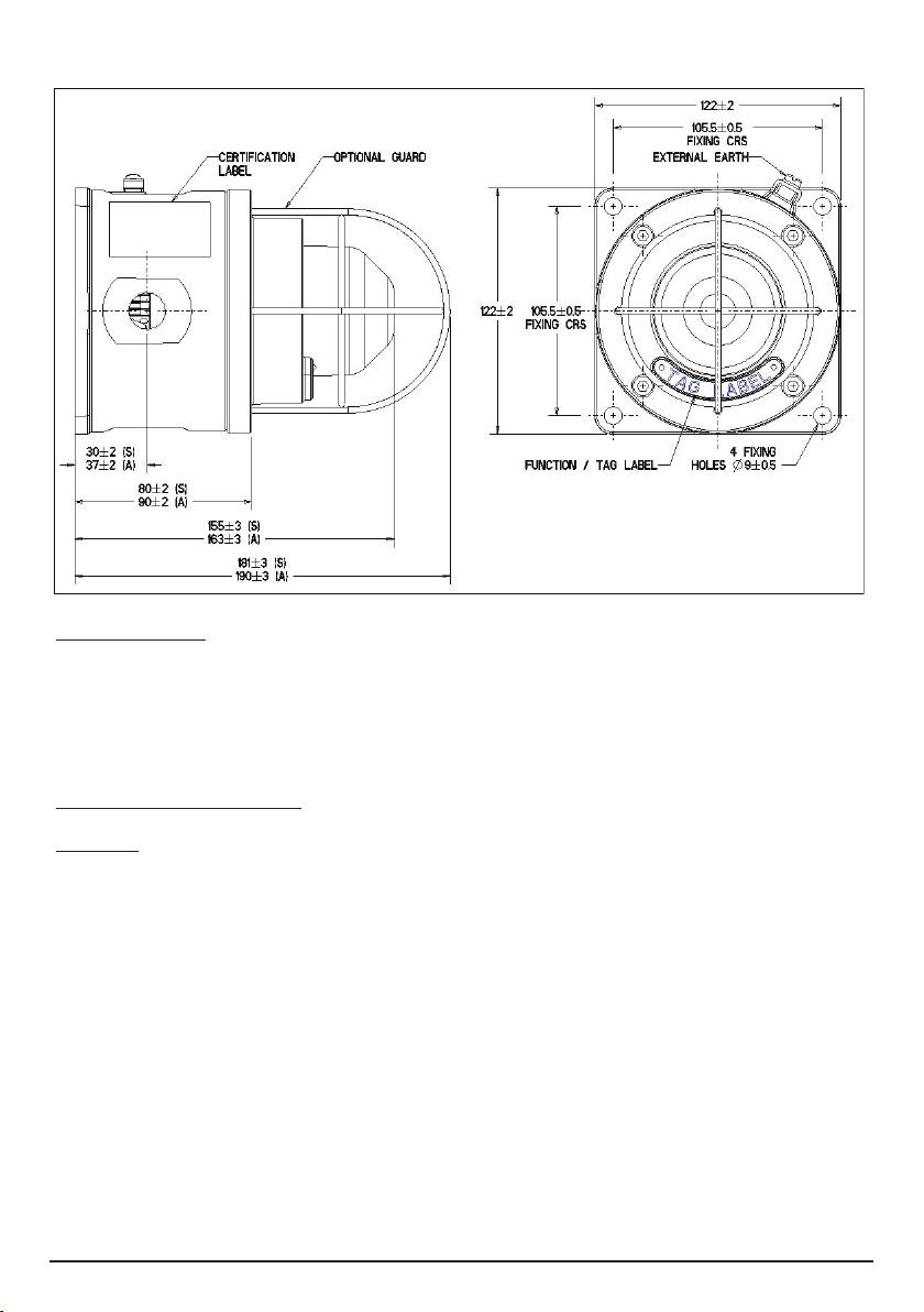
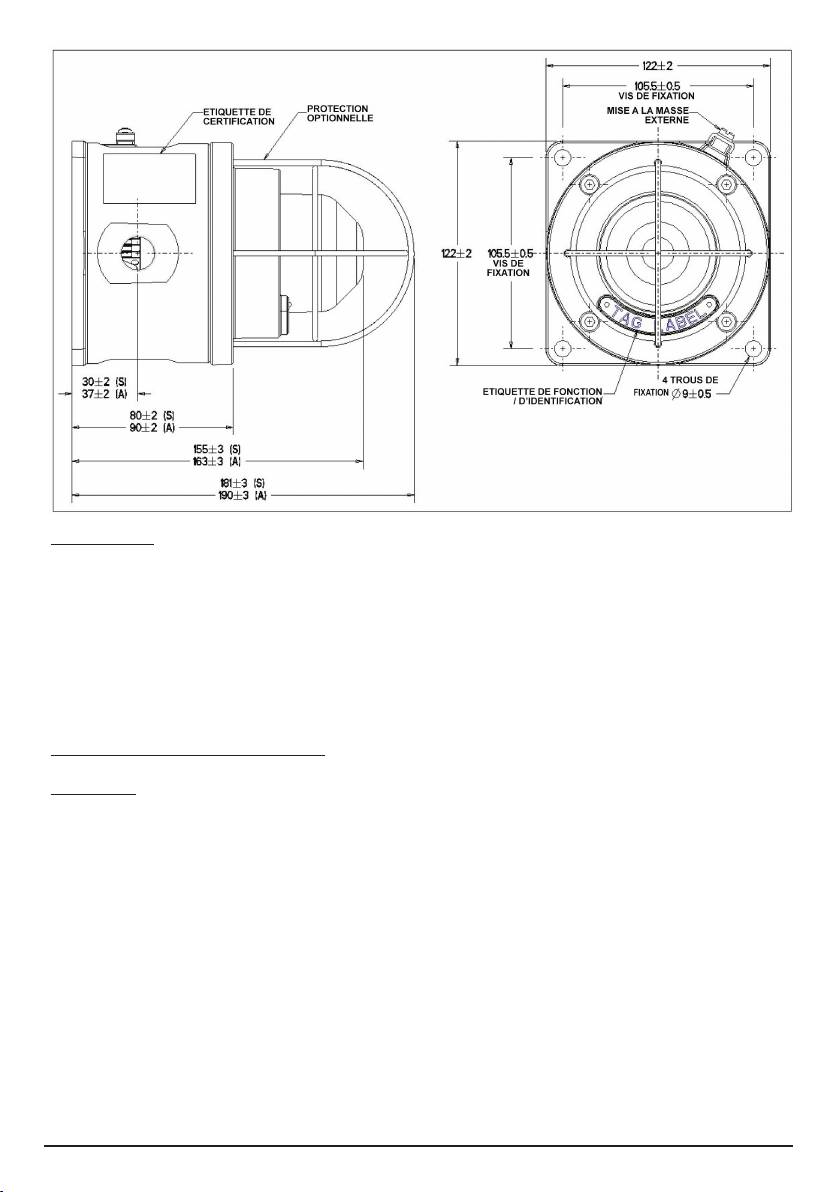
GENERAL ARRANGEMENT
4.0 MAINTENANCE
During the working life of the unit, it should require little or no maintenance. However, if abnormal or unusual
environmental conditions occur due to plant damage or accident etc., then visual inspection is recommended.
If the unit requires cleaning, then only clean exterior with a damp cloth to avoid electro-static charge build up.
If a unit fault should occur, then the unit can be repaired by MEDC. All parts of the unit are replaceable.
If you acquired a significant quantity of units, then it is recommended that spares are also made available.
Please discuss your requirements with the Technical Sales Engineers at MEDC.
5.0 CERTIFICATION/APPROVALS
IECEx units
Certified to IEC 60079-0, IEC 60079-1 and IEC 60079-31
Ex d unit (IEC certification No. IECEx BAS 09.0059)
Ex d IIC Tx (Tamb.) Gb
Ex tb IIIC Tx (Tamb.) Db IP66/IP67
3.0 OPERATION
The operating voltage of the unit is stated on the certification label. The beacon can be initiated either directly
or remotely depending on the type ordered. Please see the wiring documentation supplied with the unit for
further information.
GENERAL ARRANGEMENT
© Cooper MEDC 2010 10/10
4.0 MAINTENANCE
During the working life of the unit, it should require little or no maintenance. However, if abnormal or unusual
environmental conditions occur due to plant damage or accident etc., then visual inspection is recommended.
If the unit requires cleaning, then only clean exterior with a damp cloth to avoid electro-static charge build up.
If a unit fault should occur, then the unit can be repaired by MEDC. All parts of the unit are replaceable.
If you acquired a significant quantity of units, then it is recommended that spares are also made available.
Please discuss your requirements with the Technical Sales Engineers at MEDC.
© Cooper MEDC 2010 11/10
The IECEx certificate and product label carry the IECEx equipment protection level marking
Gb
Db
Where Gb signifies suitability for use in a Zone 1 surface industries area in the presence of gas.
Where Db signifies suitability for use in a Zone 21 surface industries area in the presence of dust.
ATEX units
Certified to EN60079-0, EN60079-1 and EN60079-31
Ex d unit (ATEX certification No. Baseefa03ATEX0222)
Ex d IIC Tx (Tamb.) Gb
Ex tb IIIC Tx (Tamb.) Db IP66/IP67
The ATEX certificate and product label carry the ATEX group and category marking:
II 2 GD
Where:
Signifies compliance with ATEX
II Signifies suitability for use in surface industries
2 Signifies suitability for use in a zone 1 area
G Signifies suitability for use in the presence of gases
D Signifies suitability for use in the presence of dust
5.0 CERTIFICATION/APPROVALS
IECEx units
Certified to IEC 60079-0, IEC 60079-1 and IEC 60079-31
Ex d unit (IEC certification No. IECEx BAS 09.0059)
Ex d IIC Tx (Tamb.) Gb
Ex tb IIIC Tx (Tamb.) Db IP66/IP67
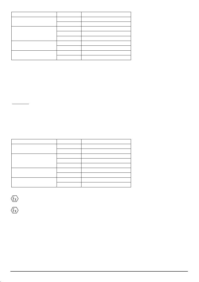
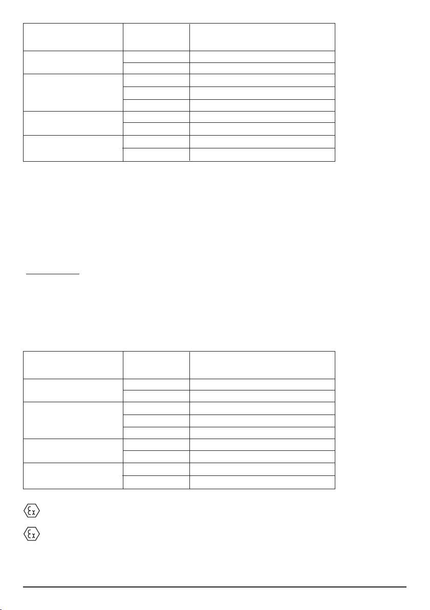
Unit type T-rating (Tx) Ambient temp range (Tamb.)
T85°C (-55°C to +55°C)
SM87LU1
T70°C (-55°C to +40°C)
T100°C (-55°C to +70°C)
SM87LU3 (Up to 10W)
T85°C (-55°C to +55°C)
T70°C (-55°C to +40°C)
T130°C (-55°C to +55°C)
SM87LU3 (11W to 25W)
T115°C (-55°C to +40°C)
T155°C (-55°C to +55°C)
SM87LU3 (26W to 40W)
T140°C (-55°C to +40°C)
© Cooper MEDC 2010 10/10
The IECEx certificate and product label carry the IECEx equipment protection level marking
Gb
Db
Where Gb signifies suitability for use in a Zone 1 surface industries area in the presence of gas.
Where Db signifies suitability for use in a Zone 21 surface industries area in the presence of dust.
ATEX units
Certified to EN60079-0, EN60079-1 and EN60079-31
Ex d unit (ATEX certification No. Baseefa03ATEX0222)
Ex d IIC Tx (Tamb.) Gb
Ex tb IIIC Tx (Tamb.) Db IP66/IP67
The ATEX certificate and product label carry the ATEX group and category marking:
Where:
SM87LU3 (11W to 25W)
SM87LU3 (26W to 40W)
II Signifies suitability for use in surface industries
2 Signifies suitability for use in a zone 1 area
G Signifies suitability for use in the presence of gases
D Signifies suitability for use in the presence of dust
SM87LU3 (Up to 10W)
II 2 GD
Signifies compliance with ATEX
SM87LU1
Unit type T-rating (Tx) Ambient temp range (Tamb.)
T100°C (-55°C to +70°C)
T130°C (-55°C to +55°C)
T115°C (-55°C to +40°C)
T155°C (-55°C to +55°C)
T140°C (-55°C to +40°C)
T85°C (-55°C to +55°C)
T70°C (-55°C to +40°C)
T85°C (-55°C to +55°C)
T70°C (-55°C to +40°C)
5.0 CERTIFICATION/APPROVALS
IECEx units
Certified to IEC 60079-0, IEC 60079-1 and IEC 60079-31
Ex d unit (IEC certification No. IECEx BAS 09.0059)
Ex d IIC Tx (Tamb.) Gb
Ex tb IIIC Tx (Tamb.) Db IP66/IP67
Unit type T-rating (Tx) Ambient temp range (Tamb.)
T85°C (-55°C to +55°C)
SM87LU1
T70°C (-55°C to +40°C)
T100°C (-55°C to +70°C)
SM87LU3 (Up to 10W)
T85°C (-55°C to +55°C)
T70°C (-55°C to +40°C)
T130°C (-55°C to +55°C)
SM87LU3 (11W to 25W)
T115°C (-55°C to +40°C)
T155°C (-55°C to +55°C)
SM87LU3 (26W to 40W)
T140°C (-55°C to +40°C)
© Cooper MEDC 2010 10/10
The IECEx certificate and product label carry the IECEx equipment protection level marking
Gb
Db
Where Gb signifies suitability for use in a Zone 1 surface industries area in the presence of gas.
Where Db signifies suitability for use in a Zone 21 surface industries area in the presence of dust.
ATEX units
Certified to EN60079-0, EN60079-1 and EN60079-31
Ex d unit (ATEX certification No. Baseefa03ATEX0222)
Ex d IIC Tx (Tamb.) Gb
Ex tb IIIC Tx (Tamb.) Db IP66/IP67
The ATEX certificate and product label carry the ATEX group and category marking:
Where:
SM87LU3 (11W to 25W)
SM87LU3 (26W to 40W)
II Signifies suitability for use in surface industries
2 Signifies suitability for use in a zone 1 area
G Signifies suitability for use in the presence of gases
D Signifies suitability for use in the presence of dust
SM87LU3 (Up to 10W)
II 2 GD
Signifies compliance with ATEX
SM87LU1
Unit type T-rating (Tx) Ambient temp range (Tamb.)
T100°C (-55°C to +70°C)
T130°C (-55°C to +55°C)
T115°C (-55°C to +40°C)
T155°C (-55°C to +55°C)
T140°C (-55°C to +40°C)
T85°C (-55°C to +55°C)
T70°C (-55°C to +40°C)
T85°C (-55°C to +55°C)
T70°C (-55°C to +40°C)
11/10 © Cooper MEDC 2010

The ATEX certificate and product label also carry the following mark:
This signifies unit compliance to the relevant European directives, in this case 94/9/EC, along with the number
of the notified body issuing the EC type examination certificate.
1180
© Cooper MEDC 2010 11/10

русский
1.0 ВВЕДЕНИЕ
Настоящие устройства с непрерывно действующими маячками предназначены для
использования в огнеопасной атмосфере и жестких условиях окружающей среды. Кожухи,
изготовленные из судостроительного сплава или нержавеющей стали, можно использовать
и в открытом море, и на суше, где сочетание легкого веса изделия с его коррозионной
устойчивостью и прочностью является незаменимым качеством.
2.0 УСТАНОВКА
Общая информация
Требования, предъявляемые к выбору, установке и эксплуатации взрывозащищенного
оборудования, должны соответствовать «Нормативным требованиям к монтажу электрических
схем Института инженеров-электриков (IEE)» и «Национальным электротехническим
нормативам» для Северной Америки. Необходимо учитывать также наличие дополнительных
федеральных и (или) местных требований.
Проследите, чтобы все гайки, болты и крепления были надежно затянуты.
Проследите, чтобы для заглушки неиспользуемых сальниковых вводов использовались только
правильно каталогизированные или сертифицированные заглушки и чтобы был выдержан
класс защиты NEMA/IP устройства.
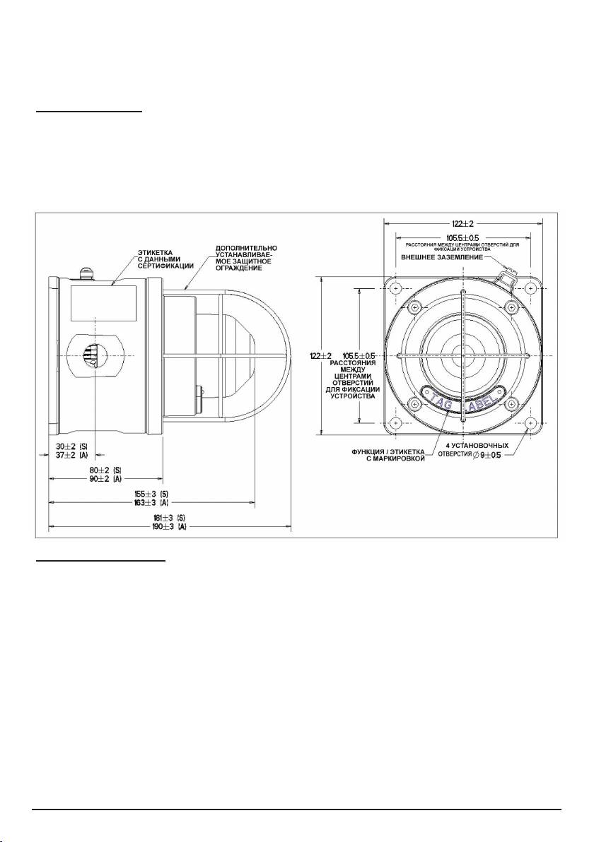
Маячок монтируется при помощи 4 установочных отверстий размером Ø9 мм в основании
устройства. Установочные отверстия рассчитаны под винты или болты размером M8.
MEDC рекомендует использовать винты из нержавеющей стали.
Блок предназначен и сертифицирован для работы в любом положении
Кабельный ввод
ОСТОРОЖНО! Прежде чем демонтировать крышку в сборе, проследите, чтобы
питание устройства было отключено, а газовая и/или пылесодержащая атмосфера
отсутствовала.
Выверните 4 винта (размер зева шестигранного ключа — 5 мм), удерживая крышку в сборе
на установочной поверхности. Держите винты в безопасном доступном месте, пока они не
установлены в крышку.
Осторожно поворачивайте крышку по часовой стрелке и против нее, при этом стаскивая ее
с установочной поверхности кожуха, чтобы получить доступ вовнутрь.
Кабельный ввод должен соответствовать спецификациям, разработанным для конкретной
прикладной задачи. MEDC рекомендует, чтобы все кабели и жилы кабелей были должным
образом идентифицированы. См. схему электропроводки, поставляемую вместе с
изделием.
Проследите, чтобы использовались только правильно каталогизированные или
сертифицированные кабельные уплотнения и чтобы узел был экранирован и правильно
заземлен.
Все кабельные уплотнения должны соответствовать классу защиты NEMA/IP маячка и быть
встроены в устройство, как того требует этот класс.
Внутренняя клемма заземления там, где она установлена, должна использоваться для
заземления оборудования, а внешняя клемма — для дополнительного заземления там, где
местные законы или власти позволяют или требуют наличия такого соединения.
По завершении заделки с большой осторожностью опустите крышку в сборе обратно на
11/10 © Cooper MEDC 2010
основание, стараясь не повредить сопрягающиеся поверхности. Проследите, чтобы при
повторной сборке кольцевое уплотнение было правильно установлено в свою канавку.
Установите на место и равномерно затяните 4 винта крышки. Проследите, чтобы между
крышкой и основанием был выдержан требуемый зазор (не более 0,15 мм).
3.0 ЭКСПЛУАТАЦИЯ
Рабочее напряжение устройства приведено на этикетке, содержащей данные сертификации.
Маячок может быть включен непосредственно или дистанционно в зависимости от типа
заданной инструкции. Более подробную информацию см. в документации по монтажным
соединениям, поставляемой вместе с устройством.
ОБЩАЯ КОМПОНОВКА
4.0 ТЕХОБСЛУЖИВАНИЕ
В течение всего срока службы устройству необходимо минимальное техобслуживание или
вообще не требуется никакого техобслуживания. Однако, если, например, из-за повреждения
или аварии установки возникают аномальные или необычные условия окружающей среды,
рекомендуется производить визуальный осмотр.
Если устройство нуждается в очистке, производите ее только для внешней его поверхности,
используя для этого кусок влажной ткани во избежание накопления электростатического
заряда.
Если в работе устройства происходят сбои, его можно отремонтировать в компании MEDC.
Может быть заменена любая деталь устройства.
Если вы приобретаете большое количество устройств, рекомендуется иметь необходимый
доступ к соответствующим запасным частям. Обсудите свои требования с инженерами службы
сбыта компании MEDC.
© Cooper MEDC 2010 11/10
3.0 ������������
������� ���������� ���������� ��������� �� ��������, ����������
������ ������������. ������ ����� ���� ������� ��������������� ���
������������ � ����������� �� ���� �������� ����������. �����
��������� ���������� ��. � ������������ �� ��������� �����������,
������������ ������ � �����������.
����� ����������
© Cooper MEDC 2010 10/10
4.0 ���������������
� ������� ����� ����� ������ ���������� ���������� �����������
��������������� ��� ������ �� ��������� �������� ���������������.
������, ����, ��������, ��-�� ����������� ��� ������ ��������� ���������
���������� ��� ��������� ������� ���������� �����, �������������
����������� ���������� ������.
���� ���������� ��������� � �������, ����������� �� ������ ��� �������
��� �����������, ��������� ��� ����� ����� ������� ����� �� ���������
���������� ������������������� ������.
���� � ������ ���������� ���������� ����, ��� ����� ��������������� �
�������� MEDC. ����� ���� �������� ����� ������ ����������.
���� �� ������������ ������� ���������� ���������, �������������
����� ����������� ������ � ��������������� �������� ������. ��������
���� ���������� � ���������� ������ ����� �������� MEDC.
5.0 СЕРТИФИКАЦИЯ/АТТЕСТАЦИЯ
Устройства класса IECEx
Сертифицированы на соответствие стандартам IEC 60079-0, IEC 60079-1 и IEC 60079-31
Блок Ex d (сертификация IEC № IECEx BAS 09.0059)
Ex d IIC Tx (Tокр.) Gb
Ex tb IIIC Tx (Tокр.) Db IP66/IP67
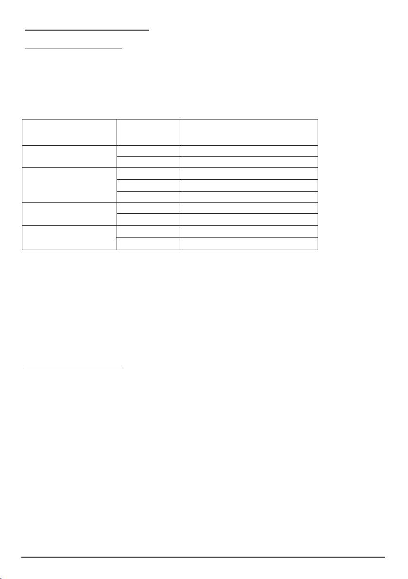
Тип блока Номинал Диапазон температур
T (Tx) окружающей среды (Tокр.)
SM87LU1 T85 °C (от -55 до +55 °C)
T70 °C (от -55 до +40 °C)
SM87LU3 (до 10 Вт) T100 °C (от -55 до +70 °C)
T85 °C (от -55 до +55 °C)
T70 °C (от -55 до +40 °C)
SM87LU3 T130 °C (от -55 до +55 °C)
(от 11 до 25 Вт) T115 °C (от -55 до +40 °C)
SM87LU3 T155 °C (от -55 до +55 °C)
(от 26 до 40 Вт) T140 °C (от -55 до +40 °C)
В сертификате IECEx и на этикетке изделия содержится маркировка IECEx уровня защиты
оборудования
Gb
Db
Где Gb означает возможность применения в наземных промышленных условиях Зоны 1 в
присутствии газа.
Где Db означает возможность применения в наземных промышленных условиях Зоны 21 в
присутствии пыли.
Устройства класса ATEX:
Сертифицированы на соответствие стандартам EN60079-0, EN60079-1 и EN60079-31
Блок Ex d (сертификация ATEX № Baseefa03ATEX0222)
Ex d IIC Tx (Tокр.) Gb
Ex tb IIIC Tx (Tокр.) Db IP66/IP67
11/10 © Cooper MEDC 2010
Тип блока Номинал Диапазон температур
T (Tx) окружающей среды (Tокр.)
SM87LU1 T85 °C (от -55 до +55 °C)
T70 °C (от -55 до +40 °C)
SM87LU3 (до 10 Вт) T100 °C (от -55 до +70 °C)
T85 °C (от -55 до +55 °C)
T70 °C (от -55 до +40 °C)
SM87LU3 T130 °C (от -55 до +55 °C)
(от 11 до 25 Вт) T115 °C (от -55 до +40 °C)
SM87LU3 T155 °C (от -55 до +55 °C)
(от 26 до 40 Вт) T140 °C (от -55 до +40 °C)
В сертификате ATEX и на этикетке изделия содержится маркировка, характеризующая группу
и категорию ATEX:
II 2 GD
Где:
означает соблюдение требований ATEX
II означает возможность использования в наземных промышленных условиях
2 означает возможность использования в условиях Зоны 1
G означает возможность использования в присутствии газов
D означает возможность использования в присутствии пыли
В сертификате ATEX и на этикетке изделия имеется также следующая отметка:
Она означает соответствие устройства имеющим отношение к данному вопросу европейским
директивам, в данном случае директиве 94/9/EC, и содержит количество уполномоченных
органов, выпускающих свидетельство о проверке образца Европейского сообщества.
© Cooper MEDC 2010 11/10
1180

Francais
1.0 INTRODUCTION
Ces balises statiques ont été conçues pour un usage dans les atmosphères inflammables et les conditions
environnementales difficiles. Les boîtiers en alliage de catégorie marine ou en acier inoxydable conviennent
à un usage en mer ou sur terre, où un poids léger combiné à une résistance à la corrosion et une solidité sont
exigés.
2.0 INSTALLATION
Généralités
Lors de l’installation et de la mise en service d’un appareil protégé contre les explosions, les spécifications de
sélection, d’installation et de fonctionnement doivent être consultées, par exemple les règlements de l’IEE en
matière de câblage et le « National Electric Code » en Amérique du Nord. Des spécifications nationales et/ou
locales additionnelles peuvent s’appliquer.
Assurez-vous que tous les écrous, les boulons et les attaches sont bien fixés.
Assurez-vous que seuls les bouchons listés ou certifiés sont utilisés pour neutraliser les presse-étoupes inutilisés,
et que l’indice NEMA/IP de l’unité est maintenu.
La balise est montée via 4 trous de fixation de Ø9 mm à la base de l’unité. Les trous de fixation ont été conçus
pour accepter une vis ou un boulon M8.
MEDC recommande l’usage de vis en acier inoxydable.
L’unité a été conçue et a été certifiée pour fonctionner selon n’importe quelle position
Terminaisons des câbles
AVERTISSEMENT : Avant d’enlever le couvercle, assurez-vous que l’alimentation est débranchée et que
l’atmosphère ne contient pas de gaz ou de poussières.
Dévissez les 4 vis (clé hexagonale A/F de 5 mm) retenant le couvercle à la base. Gardez les vis dans un endroit
accessible et sûr, dans la mesure où elles ne sont pas retenues à l’intérieur du couvercle.
Tournez doucement le couvercle de gauche à droite tout en l’éloignant de la base du boîtier afin d’accéder à
l’intérieur.
Les terminaisons des câbles doivent être conformes aux spécifications relatives au domaine d’application voulu.
MEDC recommande que tous les câbles et les âmes soient correctement identifiés. Veuillez vous référer au schéma
de câblage fourni avec le produit.
Assurez-vous que seuls les presse-étoupes correctement listés ou certifiés sont utilisés et que l’ensemble est fermé
et correctement relié à la masse.
Tous les presse-étoupes doivent posséder un indice NEMA/IP équivalent à celui de la balise et doivent être
intégrés à l’unité d’une manière qui maintienne cet indice.
La borne de masse interne, lorsqu’elle est installée, doit être utilisée pour la connexion à la masse de l’appareil,
et la borne externe sert de connexion de liaison supplémentaire lorsque les règlements ou les autorités locales
permettent ou exigent une telle connexion.
Une fois que les terminaisons ont été installées, replacez doucement le couvercle sur le boîtier en évitant d’abîmer
les surfaces de contact. Assurez-vous que le joint torique est correctement placé dans sa cannelure pendant le
réassemblage. Replacez et resserrez de manière égale les 4 vis du couvercle. Assurez-vous que l’écart requis
(0,15 mm maximum) est maintenu entre le couvercle et la base.
3.0 FONCTIONNEMENT
La tension nominale de l’unité est indiquée sur l’étiquette de certification. La balise peut être mise en marche
directement ou à distance selon la version commandée. Pour plus d’informations, veuillez vous référer à la
documentation de câblage fournie avec l’unité.
11/10 © Cooper MEDC 2010
4.0 ENTRETIEN
L’unité ne devrait exiger que très peu, ou pas, d’entretien au cours de sa durée de vie. Toutefois, si des conditions
environnementales anormales ou inhabituelles se produisent suite à un accident d’usine etc., une inspection
visuelle de l’appareil est recommandée.
Si l’unité doit être nettoyée, ne nettoyez que l’extérieur avec un chiffon humide pour éviter le développement
de charges électrostatiques.
Si une unité tombe en panne, celle-ci pourra être réparée par MEDC. Tous les composants de l’unité sont
remplaçables.
Si vous avez acquis de nombreuses unités, il est recommandé de commander des pièces de rechange. Veuillez
faire part de vos spécifications aux ingénieurs technico-commerciaux de MEDC.
5.0 CERTIFICATION/HOMOLOGATIONS
Unités IECEx
Certifiées aux normes IEC 60079-0, IEC 60079-1 et IEC 60079-31
Unité Ex d (n° de certification IEC IECEx BAS 09.0059)
Ex-d IIC Tx (Tamb.) Gb
Ex-tb IIIC Tx (Tamb.) Db IP66/IP67
© Cooper MEDC 2010 11/10
3.0 FONCTIONNEMENT
La tension nominale de l’unité est indiquée sur l’étiquette de certification. La balise peut être mise en marche
directement ou à distance selon la version commandée. Pour plus d’informations, veuillez vous référer à la
documentation de câblage fournie avec l’unité.
DISPOSITION GENERALE
© Cooper MEDC 2010 10/10
4.0 ENTRETIEN
L’unité ne devrait exiger que très peu, ou pas, d’entretien au cours de sa durée de vie. Toutefois, si des
conditions environnementales anormales ou inhabituelles se produisent suite à un accident d’usine etc., une
inspection visuelle de l’appareil est recommandée.
Si l’unité doit être nettoyée, ne nettoyez que l’extérieur avec un chiffon humide pour éviter le développement
de charges électrostatiques.
Si une unité tombe en panne, celle-ci pourra être réparée par MEDC. Tous les composants de l’unité sont
remplaçables.
Si vous avez acquis de nombreuses unités, il est recommandé de commander des pièces de rechange.
Veuillez faire part de vos spécifications aux ingénieurs technico-commerciaux de MEDC.
Type d’unité Niveau Plage de température
T (Tx) ambiante (Tamb.)
SM87LU1 T85 °C (-55°C à +55°C)
T70 °C (-55°C à +40°C)
SM87LU3 jusqu’à 10 W) T100 °C (-55 °C à +70°C)
T85 °C (-55 °C à +55°C)
T70 °C (-55 °C à +40°C)
SM87LU3 (11 W à 25 W) T130 °C (-55 °C à +55°C)
T115 °C (-55 °C à +40°C)
SM87LU3 (26 W à 40 W) T155 °C (-55 °C à +55°C)
T140 °C (-55 °C à +40°C)
Le certificat IECEx et l’étiquette de produit indiquent le niveau de protection IECEx de l’appareil
Gb
Db
Où Gb indique l’aptitude de l’appareil à un usage dans les industries à ciel ouvert de type Zone 1 avec présence
de gaz.
Où Db indique l’aptitude de l’appareil à un usage dans les industries à ciel ouvert de type Zone 21 avec
présence de poussière.
Unités ATEX
Certifiées aux normes EN 60079-0, EN 60079-1 et EN 60079-31
Unité Ex d (n° de certification ATEX Baseefa03ATEX0222)
Ex-d IIC Tx (Tamb.) Gb
Ex-tb IIIC Tx (Tamb.) Db IP66/IP67
Type d’unité Niveau Plage de température
T (Tx) ambiante (Tamb.
SM87LU1 T85 °C (-55°C à +55°C)
T70 °C (-55°C à +40°C)
SM87LU3 jusqu’à 10 W) T100 °C (-55 °C à +70°C)
T85 °C (-55 °C à +55°C)
T70 °C (-55 °C à +40°C)
SM87LU3 (11 W à 25 W) T130 °C (-55 °C à +55°C)
T115 °C (-55 °C à +40°C)
SM87LU3 (26 W à 40 W) T155 °C (-55 °C à +55°C)
T140 °C (-55 °C à +40°C)
Le certificat ATEX et l’étiquette de produit indiquent le groupe et la catégorie ATEX :
II 2 GD
Où :
indique la conformité de l’appareil aux normes ATEX
II indique l’aptitude de l’appareil à un usage dans les industries à ciel ouvert
2 indique l’aptitude de l’appareil à un usage dans un secteur de type zone 1
11/10 © Cooper MEDC 2010
G indique l’aptitude de l’appareil à un usage en présence de gaz
D indique l’aptitude de l’appareil à un usage en présence de poussière
Le certificat ATEX et l’étiquette du produit portent également l’inscription suivante :
Cela indique la conformité de l’unité aux directives européennes appropriées, 94/9/EC dans ce cas, ainsi que
le numéro de l’organisme distribuant le certificat d’examen de type EC.
© Cooper MEDC 2010 11/10
1180

Deutsch
1.0 EINFÜHRUNG
Diese Dauerleuchten wurden für die Verwendung in entzündlichen Atmosphären und unter rauen
Umgebungsbedingungen entwickelt. Die Gehäuse aus seewasserfesten Legierungen oder Edelstahl eignen sich
zur Verwendung auf See und an Land, wenn eine Kombination aus geringem Gewicht, Korrosionsbeständigkeit
und Festigkeit gefragt ist.
2.0 INSTALLATION
Allgemeines
Bei Installation und Betrieb explosionsgeschützter elektrischer Einrichtungen sind die entsprechenden
landesspezifischen Regelungen betreffs Auswahl, Installation und Betrieb (z. B.: „IEE Wiring Regulations“
[Installationsvorschriften der Vereinigung Britischer Elektroingenieure] und die NEC-Vorschriften in Nordamerika)
zu beachten. Zusätzlich können auch nationale und/oder lokale Bestimmungen Anwendung finden.
Stellen Sie sicher, dass alle Muttern, Schrauben und Befestigungselemente fest sitzen.
Stellen Sie sicher, dass nur die korrekt gelisteten oder zertifizierten Verschlussstopfen zum Verschließen
unbenutzter Anschlussstutzen-Öffnungen verwendet werden, und dass die IP-/NEMA-Schutzklasse der Einheit
erhalten bleibt.
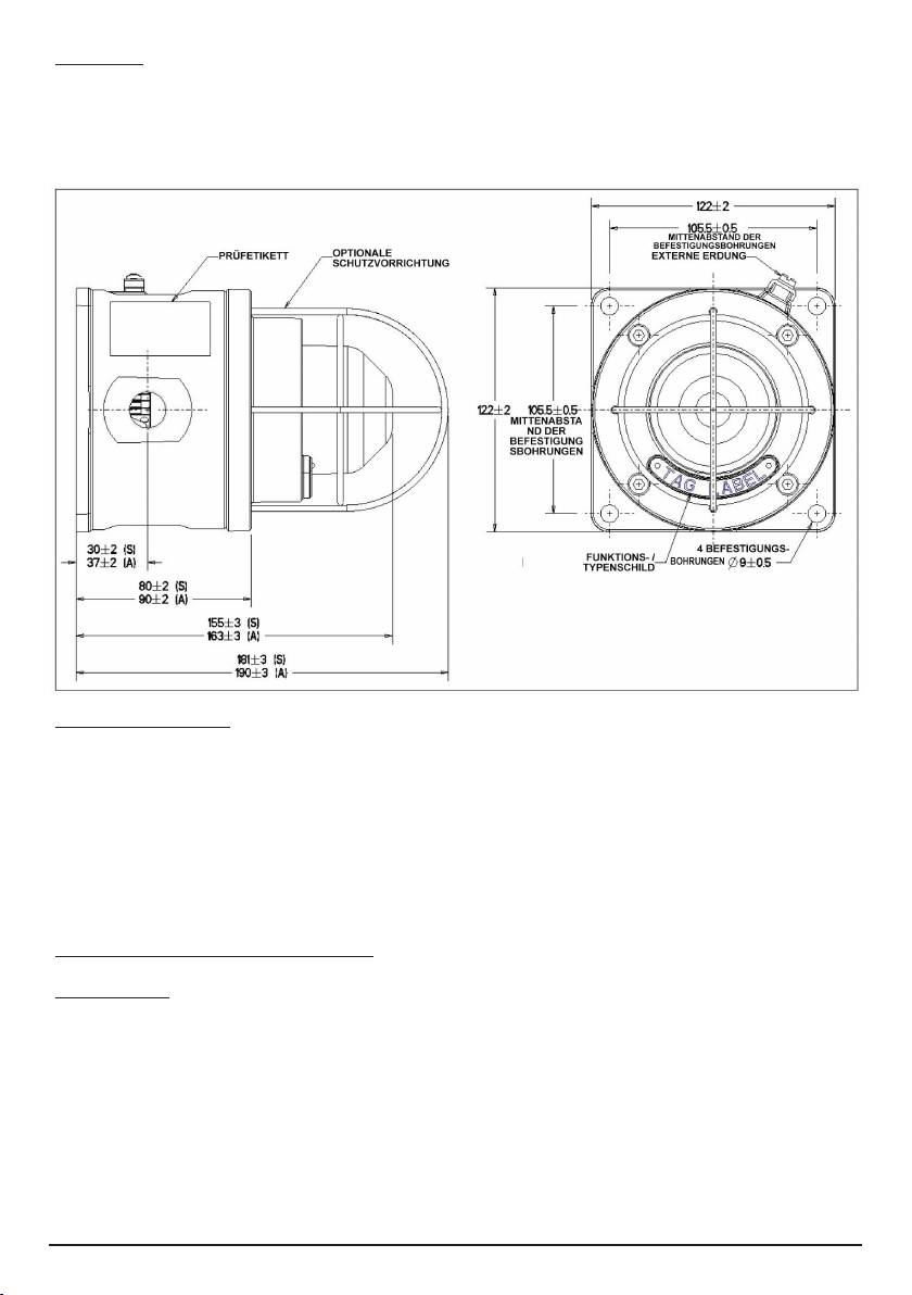
Die Dauerleuchte wird mithilfe der vier Ø9 mm-Bohrungen im Unterteil der Einheit montiert. Die
Befestigungsbohrungen wurden für M8 Schrauben oder -Bolzen konstruiert.
MEDC empfiehlt die Verwendung von Edelstahlschrauben.
Das Gerät wurde dafür entwickelt, in jeder Ausrichtung zu funktionieren, und ist auch entsprechend
zertifiziert.
Kabelendverschluss
VORSICHT: Stellen Sie vor Entfernung des Deckels sicher, dass das Gerät von der Spannungsversorgung
isoliert ist und weder eine Gas- noch eine Staubatmosphäre vorhanden ist.
Lösen Sie die vier Schrauben (5 mm A/F Sechskantstiftschlüssel), mit denen der Deckel am Unterteil befestigt ist.
Bewahren Sie die Schrauben sicher und leicht erreichbar auf, da sie nicht im Deckel verbleiben.
Um das Geräteinnere freizulegen, drehen Sie den Deckel vorsichtig im Uhrzeigersinn und gegen den
Uhrzeigersinn, und ziehen Sie ihn gleichzeitig vom Unterteil des Gehäuses weg, bis er sich löst.
Der Kabelendverschluss ist in Übereinstimmung mit den für die entsprechende Anwendung geltenden
Spezifikationen durchzuführen. MEDC empfiehlt, alle Kabel und Adern ordnungsgemäß zu kennzeichnen.
Nutzen Sie dazu den mit dem Produkt gelieferten Schaltplan.
Stellen Sie sicher, dass nur korrekt gelistete oder zertifizierte Anschlussstutzen benutzt werden, und dass die
Baugruppe ummantelt und ordnungsgemäß geerdet ist.
Alle Anschlussstutzen müssen über die gleiche IP-/NEMA-Schutzklasse wie die Dauerleuchte verfügen und so
in das Gerät integriert werden, dass diese Klasse aufrechterhalten wird.
Falls eingebaut, muss die interne Erdungsklemme zur Erdung des Ausrüstungsgegenstands verwendet werden,
und die externe Klemme ist für eine zusätzliche Masseverbindung bestimmt, die dort verwendet wird, wo die
örtlichen Vorschriften oder Behörden diese Verbindung zulassen oder vorschreiben.
Nach dem Kabelendverschluss senken Sie den Deckel wieder auf das Unterteil ab. Gehen Sie dabei vorsichtig vor,
um Schäden an den Kontaktflächen zu vermeiden. Stellen Sie sicher, dass der O-Ring beim Zusammenbau korrekt
in seiner Nut sitzt. Setzen Sie die vier Deckelschrauben ein, und ziehen Sie sie dann gleichmäßig an. Stellen Sie
sicher, dass der erforderliche Abstand (max. 0,15 mm) zwischen Deckel und Unterteil beibehalten wird.
11/10 © Cooper MEDC 2010
3.0 BETRIEB
Die Betriebsspannung der Einheit steht auf dem Prüfetikett. Die Dauerleuchte kann – je nach bestellter Ausführung
– entweder direkt oder per Fernbedienung eingeschaltet werden. Weitere Einzelheiten entnehmen Sie den mit
dem Produkt gelieferten Schaltplan und Verdrahtungsunterlagen.
ÜBERSICHTSZEICHNUNG
© Cooper MEDC 2010 11/10
3.0 BETRIEB
Die Betriebsspannung der Einheit steht auf dem Prüfetikett. Die Dauerleuchte kann – je nach bestellter
Ausführung – entweder direkt oder per Fernbedienung eingeschaltet werden. Weitere Einzelheiten
entnehmen Sie den mit dem Produkt gelieferten Schaltplan und Verdrahtungsunterlagen.
ÜBERSICHTSZEICHNUNG
© Cooper MEDC 2010 10/10
4.0 INSTANDHALTUNG
Während des Arbeitslebens des Geräts sollten nur geringe oder gar keine Instandhaltungsarbeiten
erforderlich sein. Wenn allerdings aufgrund eines Anlagenschadens oder Unfalls etc. ungewöhnliche
Umgebungsbedingungen auftreten, wird eine Sichtprüfung empfohlen.
Wenn das Gerät gereinigt werden muss, reinigen Sie es nur von außen mit einem feuchten Tuch, um eine
elektrostatische Aufladung zu vermeiden.
Sollte ein Fehler im Gerät auftreten, kann es von MEDC instandgesetzt werden. Alle Bauteile können ersetzt
werden.
Wenn Sie größere Stückzahlen erworben haben, wird die Lagerhaltung von Ersatzaggregaten empfohlen.
Bitte besprechen Sie Ihren Ersatzteilbedarf mit den Vertriebsingenieuren von MEDC.
4.0 INSTANDHALTUNG
Während des Arbeitslebens des Geräts sollten nur geringe oder gar keine Instandhaltungsarbeiten erforderlich
sein. Wenn allerdings aufgrund eines Anlagenschadens oder Unfalls etc. ungewöhnliche Umgebungsbedingungen
auftreten, wird eine Sichtprüfung empfohlen.
Wenn das Gerät gereinigt werden muss, reinigen Sie es nur von außen mit einem feuchten Tuch, um eine
elektrostatische Aufladung zu vermeiden.
Sollte ein Fehler im Gerät auftreten, kann es von MEDC instandgesetzt werden. Alle Bauteile können ersetzt
werden.
Wenn Sie größere Stückzahlen erworben haben, wird die Lagerhaltung von Ersatzaggregaten empfohlen. Bitte
besprechen Sie Ihren Ersatzteilbedarf mit den Vertriebsingenieuren von MEDC.
5.0 ZERTIFIZIERUNG / GENEHMIGUNGEN
IECEx Einheiten
Zertifiziert gemäß IEC 60079-0, IEC 60079-1 und IEC 60079-31
Ex d Einheit (IEC-Zertifizierungsnummer IECEx BAS 09.0059)
Ex d IIC Tx (Tumg.) Gb
Ex tb IIIC Tx (Tumg.) Db IP66/IP67
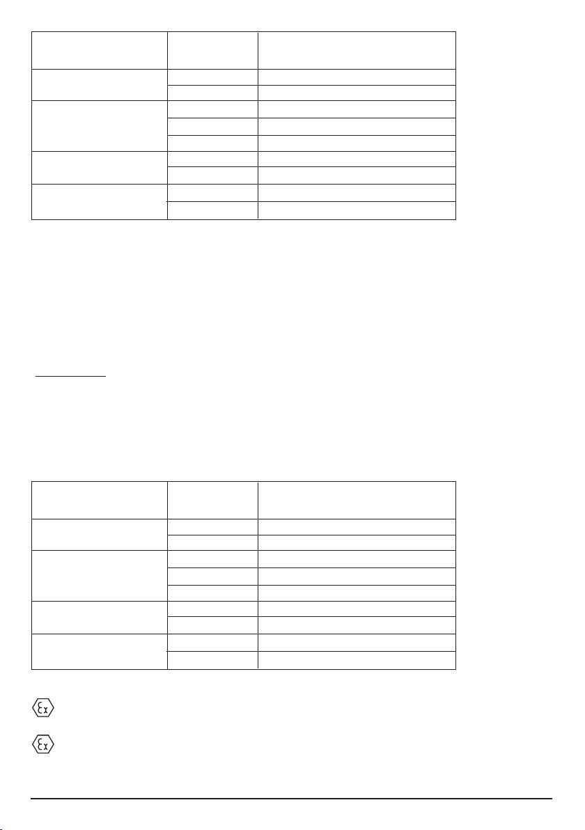
Gerätetyp Temperatur Umgebungstemperaturbereic
klasse (Tx) h (Tumg.)
SM87LU1 T85 °C (-55°C bis +55°C)
T70 °C (-55°C bis +40°C)
SM87LU3 (Bis 10 W) T100 °C (-55 °C bis +70°C)
T85 °C (-55 °C bis +55°C)
T70 °C (-55 °C bis +40°C)
SM87LU3 T130 °C (-55 °C bis +55°C)
(11 W bis 25 W) T115 °C (-55 °C bis +40°C)
SM87LU3 T155 °C (-55 °C bis +55°C)
(26 W bis 40 W) T140 °C (-55 °C bis +40°C)
Das IECEx-Zertifikat und das Produktetikett tragen die IECEx-Kennzeichnung zum Geräte-Schutzniveau:
Gb
Db
Dabei steht Gb für die Eignung zur Verwendung in einem Bereich der „Zone 1“, Übertageindustrien in gashaltigen
Bereichen.
Dabei steht Db für die Eignung zur Verwendung in einem Bereich der „Zone 21“, Übertageindustrien in
staubhaltigen Bereichen.
ATEX Einheiten
Zertifiziert gemäß EN 60079-0, EN 60079-1 und EN 60079-31
Ex d Einheit (ATEX-Zertifizierungsnummer Baseefa03ATEX0222)
Ex d IIC Tx (Tumg.) Gb
Ex tb IIIC Tx (Tumg.) Db IP66/IP67
Gerätetyp Temperatur Umgebungstemperaturbereic
klasse (Tx) h (Tumg.)
SM87LU1 T85 °C (-55°C bis +55°C)
T70 °C (-55°C bis +40°C)
SM87LU3 (Bis 10 W) T100 °C (-55 °C bis +70°C)
T85 °C (-55 °C bis +55°C)
T70 °C (-55 °C bis +40°C)
SM87LU3 T130 °C (-55 °C bis +55°C)
(11 W bis 25 W) T115 °C (-55 °C bis +40°C)
SM87LU3 T155 °C (-55 °C bis +55°C)
(26 W bis 40 W) T140 °C (-55 °C bis +40°C)
Das ATEX-Zertifikat und das Produktetikett tragen die ATEX-Gruppen und -Kategoriekennzeichnung:
II 2 GD
Dabei steht:
für die Einhaltung der ATEX-Vorschriften,
11/10 © Cooper MEDC 2010
II für die Eignung zur Verwendung in Übertageindustrien,
2 für die Eignung zur Verwendung in einem Bereich der „Zone 1“,
G für die Eignung zur Verwendung in gashaltigen Bereichen,
D für die Eignung zur Verwendung in staubhaltigen Bereichen.
Das ATEX-Zertifikat und das Produktetikett tragen außerdem folgendes Zeichen:
Dieses Zeichen bedeutet, dass das Gerät die anzuwendenden EU-Richtlinien erfüllt, in diesem Fall 94/9/
EG. Außerdem gibt es die Nummer der registrierten Behörde an, die die EG-Baumusterprüfbescheinigung
ausgefertigt hat.
© Cooper MEDC 2010 11/10
1180

Português
1.0 INTRODUCCIÓN
Estas balizas fijas han sido diseñadas para su uso en atmósferas inflamables y bajo condiciones ambientales
rigurosas. Las cajas de aleación de calidad marítima o de acero inoxidable son aptas para el uso en exteriores
o interiores, donde es necesario que sean livianas, que resistan la corrosión y que sean muy resistentes.
2.0 INSTALACIÓN
General
Al instalar y poner en funcionamiento equipos con protección contra explosiones, se deberán consultar los
requisitos para la selección, instalación y funcionamiento, por ejemplo, las normas de cableado del Instituto
de Ingenieros Eléctricos (IEE, por sus siglas en inglés) y el Código Eléctrico Nacional (NEC, por sus siglas en
inglés) de Norteamérica. Es posible que se apliquen otros requisitos nacionales o locales.
Asegúrese de que todas las tuercas, los pernos y las fijaciones estén firmemente ajustados.
Asegúrese de utilizar solamente los tapones de sellado correctos, enumerados o certificados, para obturar los
puntos de entrada de los collarines que no se usen y también de que se mantenga la calificación NEMA/IP
de la unidad.
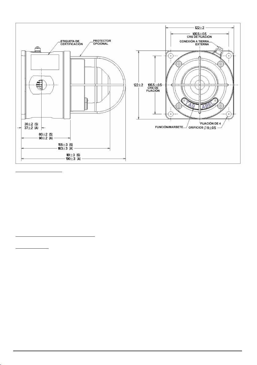
La baliza se monta a través de los 4 orificios de fijación de Ø9 mm que se encuentran en la base de la unidad.
Los orificios de fijación han sido diseñados para aceptar pernos o tornillos M8.
MEDC recomienda utilizar tornillos de acero inoxidable.
La unidad ha sido diseñada y certificada para que funcione a cualquier altitud.
Caja terminal
PRECAUCIÓN: Antes de quitar la tapa, asegúrese de que la alimentación eléctrica de la unidad esté aislada
y de que no haya presencia de gas o polvo.
Desatornille los 4 tornillos (5 mm de cabeza hexagonal A/F) mientras sostiene la tapa sobre la base. Guarde
los tornillos en un lugar seguro y accesible, ya que no se mantienen en la tapa.
Gire suavemente la tapa en sentido horario y antihorario, mientras tira de ella para sacarla de la base de la
caja y así obtener acceso al interior.
La caja terminal debe cumplir con las especificaciones correspondientes a la aplicación solicitada. MEDC
recomienda que todos los cables y conductores estén identificados correctamente. Consulte el diagrama de
conexiones suministrado con el producto.
Asegúrese de utilizar sólo los collarines correctos, enumerados o certificados y de que la unidad esté oculta y
puesta a tierra correctamente.
Todos los collarines de cables deben ser de una calificación NEMA/IP equivalente a la de la baliza y deben
estar integrados con la unidad, para mantener la calificación.
El borne de puesta a tierra interno, cuando esté fijado, se debe utilizar para la conexión a tierra del equipo y
el borne externo, para un empalme adicional, donde los códigos o autoridades locales permitan o exijan ese
tipo de conexiones.
Una vez finalizada la terminación, baje cuidadosamente la tapa sobre la base y evite dañar las superficies de
acoplamiento. Mientras vuelve a armar la unidad, asegúrese de que la junta tórica esté ubicada correctamente
en la ranura. Vuelva a colocar y ajuste firme y uniformemente los 4 tornillos de la tapa. Asegúrese de mantener
el espacio requerido (0,15 mm máximo) entre la tapa y la base.
3.0 FUNCIONAMIENTO
El voltaje de funcionamiento de la unidad se indica en la etiqueta de certificación. La baliza se puede encender
directamente o a distancia, según el tipo que se solicite. Para obtener más información, consulte la documentación
de cableado que se suministra con la unidad.
11/10 © Cooper MEDC 2010
4.0 MANTENIMIENTO
Durante su vida útil, la unidad necesitará poco o ningún tipo de mantenimiento. Sin embargo, si se presentan
condiciones ambientales anormales o poco frecuentes, debido a una avería o accidente en la planta, se
recomienda efectuar una inspección visual.
Si la unidad necesita limpieza, limpie solamente el exterior con un paño húmedo para evitar la acumulación
de cargas electrostáticas.
Si se presenta una falla en la unidad, MEDC puede repararla. Todas las piezas de la unidad son
reemplazables.
Si adquirió una cantidad importante de unidades, le recomendamos que tenga disponibles unidades de repuesto.
Los ingenieros de Ventas Técnicas de MEDC podrán asesorarlo según sus requisitos.
5.0 CERTIFICACIÓN/APROBACIONES
Unidades IECEx
Certificadas con IEC 60079-0, IEC 60079-1 e IEC 60079-31
Unidad Ex d (N.º de certificación IEC IECEx BAS 09.0059)
Ex d IIC Tx (Tamb.) Gb
Ex tb IIIC Tx (Tamb.) Db IP66/IP67
© Cooper MEDC 2010 11/10
3.0 FUNCIONAMIENTO
El voltaje de funcionamiento de la unidad se indica en la etiqueta de certificación. La baliza se puede
encender directamente o a distancia, según el tipo que se solicite. Para obtener más información, consulte la
documentación de cableado que se suministra con la unidad.
DISPOSICIÓN GENERAL
© Cooper MEDC 2010 10/10
4.0 MANTENIMIENTO
Durante su vida útil, la unidad necesitará poco o ningún tipo de mantenimiento. Sin embargo, si se presentan
condiciones ambientales anormales o poco frecuentes, debido a una avería o accidente en la planta, se
recomienda efectuar una inspección visual.
Si la unidad necesita limpieza, limpie solamente el exterior con un paño húmedo para evitar la acumulación
de cargas electrostáticas.
Si se presenta una falla en la unidad, MEDC puede repararla. Todas las piezas de la unidad son
reemplazables.
Si adquirió una cantidad importante de unidades, le recomendamos que tenga disponibles unidades de
repuesto. Los ingenieros de Ventas Técnicas de MEDC podrán asesorarlo según sus requisitos.
DISPOSICIÓN GENERAL
Tipo de unidad Calificación T Rango de temperatura
(Tx) ambiente (Tamb.)
SM87LU1 T85 °C (-55°C a +55°C)
T70 °C (-55°C a +40°C)
SM87LU3 (hasta 10 W) T100 °C (-55 °C a +70°C)
T85 °C (-55 °C a +55°C)
T70 °C (-55 °C a +40°C)
SM87LU3 T130 °C (-55 °C a +55°C)
(desde 11 W hasta 25 W) T115 °C (-55 °C a +40°C)
SM87LU3 T155 °C (-55 °C a +55°C)
(26 W a 40 W) T140 °C (-55 °C a +40°C)
El certificado IECEx y la etiqueta del producto indican la marca del nivel de protección IECEx del equipo
Gb
Db
Donde Gb significa que es apto para el uso en el área de industrias de superficie de Zona 1, en presencia de
gas.
Donde Db significa que es apto para el uso en el área de industrias de superficie de Zona 21, en presencia
de polvo.
Unidades ATEX
Certificadas con EN 60079-0, EN 60079-1 y EN 60079-31
Unidad Ex d (N.º de certificación ATEX Baseefa03ATEX0222)
Ex d IIC Tx (Tamb.) Gb
Ex tb IIIC Tx (Tamb.) Db IP66/IP67
Tipo de unidad Calificación T Rango de temperatura
(Tx) ambiente (Tamb.)
SM87LU1 T85 °C (-55°C a +55°C)
T70 °C (-55°C a +40°C)
SM87LU3 (hasta 10 W) T100 °C (-55 °C a +70°C)
T85 °C (-55 °C a +55°C)
T70 °C (-55 °C a +40°C)
SM87LU3 T130 °C (-55 °C a +55°C)
(desde 11 W hasta 25 W) T115 °C (-55 °C a +40°C)
SM87LU3 T155 °C (-55 °C a +55°C)
(26 W a 40 W) T140 °C (-55 °C a +40°C)
El certificado y la etiqueta de producto ATEX indican las marcas de grupo y categoría ATEX:
II 2 GD
Donde:
Significa que cumple con ATEX
II Significa que es apto para el uso en industrias de superficie
2 Significa que es apto para su uso en un área de Zona 1
11/10 © Cooper MEDC 2010

G Significa que es apto para el uso en presencia de gases
D Significa que es apto para el uso en presencia de polvo
El certificado ATEX y la etiqueta del producto, además, indican la siguiente marca:
Significa que la unidad cumple con las directivas europeas relevantes, en este caso 94/9/EC, junto con la
cantidad de los organismos notificados que emiten el certificado de examen tipo EC.
1180
© Cooper MEDC 2010 11/10

11/10 © Cooper MEDC 2010

© Cooper MEDC 2010 11/10

Cooper MEDC Ltd, Colliery Road, Pinxton, Nottingham NG16 6JF, United Kingdom.
Tel: +44 (0)1773 864100
E-Mail: medc.sales@cooperindustries.com medc.orders@cooperindustries.com MEDC Stock No.
Web: www.medc.com TM158-ISSC
11/10 © Cooper MEDC 2010
