MSI Wind Board 330: instruction
Class: Computer equipment, hardware, accessories
Type: Motherboard
Manual for MSI Wind Board 330
Wind Board 330
MS-7314 (v2.X) Mainboard
G52-73141X8
i

Copyright Notice
The material in this document is the intellectual property of MICRO-STAR
INTERNATIONAL. We take every care in the preparation of this document, but no
guarantee is given as to the correctness of its contents. Our products are under
continual improvement and we reserve the right to make changes without notice.
Trademarks
All trademarks are the properties of their respective owners.
NVIDIA, the NVIDIA logo, DualNet, and nForce are registered trademarks or trade-
marks of NVIDIA Corporation in the United States and/or other countries.
AMD, Athlon™, Athlon™ XP, Thoroughbred™, and Duron™ are registered trade-
marks of AMD Corporation.
®
®
Intel
and Pentium
are registered trademarks of Intel Corporation.
®
PS/2 and OS
/2 are registered trademarks of International Business Machines
Corporation.
®
Windows
NT/XP are registered trademarks of Microsoft Corporation.
®
Netware
is a registered trademark of Novell, Inc.
®
Award
is a registered trademark of Phoenix Technologies Ltd.
®
AMI
is a registered trademark of American Megatrends Inc.
Revision History
Revision Revision History Date
V1.0 First release for Europe November 2008
Technical Support
If a problem arises with your system and no solution can be obtained from the user’s
manual, please contact your place of purchase or local distributor. Alternatively,
please try the following help resources for further guidance.
Visit the MSI website for FAQ, technical guide, BIOS updates, driver updates,
and other information: http://global.msi.com.tw/index.php?
func=service
Contact our technical staff at: http://ocss.msi.com.tw
ii
Safety Instructions
1. Always read the safety instructions carefully.
2. Keep this User’s Manual for future reference.
3. Keep this equipment away from humidity.
4. Lay this equipment on a reliable flat surface before setting it up.
5. The openings on the enclosure are for air convection hence protects the equip-
ment from overheating. DO NOT COVER THE OPENINGS.
6. Make sure the voltage of the power source and adjust properly 110/220V be-
fore connecting the equipment to the power inlet.
7. Place the power cord such a way that people can not step on it. Do not place
anything over the power cord.
8. Always Unplug the Power Cord before inserting any add-on card or module.
9. All cautions and warnings on the equipment should be noted.
10.Never pour any liquid into the opening that could damage or cause electrical
shock.
11. If any of the following situations arises, get the equipment checked by service
personnel:
† The power cord or plug is damaged.
† Liquid has penetrated into the equipment.
† The equipment has been exposed to moisture.
† The equipment does not work well or you can not get it work according to
User’s Manual.
† The equipment has dropped and damaged.
† The equipment has obvious sign of breakage.
12. DO NOT LEAVE THIS EQUIPMENT IN AN ENVIRONMENT UNCONDITIONED, STOR-
0
0
AGE TEMPERATURE ABOVE 60
C (140
F), IT MAY DAMAGE THE EQUIPMENT.
CAUTION: Danger of explosion if battery is incorrectly replaced.
Replace only with the same or equivalent type recommended by the
manufacturer.
iii

FCC-B Radio Frequency Interference Statement
This equipment has been
tested and found to comply
with the limits for a Class B
digital device, pursuant to Part
15 of the FCC Rules. These limits are designed to provide reasonable protection
against harmful interference in a residential installation. This equipment generates,
uses and can radiate radio frequency energy and, if not installed and used in accor-
dance with the instructions, may cause harmful interference to radio communications.
However, there is no guarantee that interference will not occur in a particular
installation. If this equipment does cause harmful interference to radio or television
reception, which can be determined by turning the equipment off and on, the user is
encouraged to try to correct the interference by one or more of the measures listed
below.
† Reorient or relocate the receiving antenna.
† Increase the separation between the equipment and receiver.
† Connect the equipment into an outlet on a circuit different from that to
which the receiver is connected.
† Consult the dealer or an experienced radio/television technician for help.
Notice 1
The changes or modifications not expressly approved by the party responsible for
compliance could void the user’s authority to operate the equipment.
Notice 2
Shielded interface cables and A.C. power cord, if any, must be used in order to
comply with the emission limits.
VOIR LA NOTICE D’INSTALLATION AVANT DE RACCORDER AU RESEAU.
Micro-Star International
MS-7314
This device complies with Part 15 of the FCC Rules. Operation is subject to the
following two conditions:
(1) this device may not cause harmful interference, and
(2) this device must accept any interference received, including interference that
may cause undesired operation.
iv
WEEE (Waste Electrical and Electronic Equipment) Statement
v
vi
vii

CONTENTS
Copyright Notice................................................................................................ii
Trademarks........................................................................................................ii
Revision History................................................................................................ii
Technical Support.............................................................................................ii
Safety Instructions..........................................................................................iii
FCC-B Radio Frequency Interference Statement.........................................iv
WEEE (Waste Electrical and Electronic Equipment) Statement.....................v
English...........................................................................................................En-1
Mainboard Specifications...........................................................................En-2
Quick Components Guide...........................................................................En-4
Memory.....................................................................................................En-5
Power Supply............................................................................................En-7
Back Panel.................................................................................................En-8
Connectors..............................................................................................En-10
Jumper....................................................................................................En-15
Slot..........................................................................................................En-16
BIOS Setup..............................................................................................En-17
Software Information...............................................................................En-23
Deutsch.........................................................................................................De-1
Spezifikationen.........................................................................................De-2
Komponenten-Übersicht...........................................................................De-4
Speicher...................................................................................................De-5
Stromversorgung......................................................................................De-7
Rücktafel..................................................................................................De-8
Anschlüsse............................................................................................De-10
Steckbrücke............................................................................................De-15
Steckplätze.............................................................................................De-16
BIOS Setup.............................................................................................De-17
Software-Information..............................................................................De-23
viii

Français..........................................................................................................Fr-1
Spécifications............................................................................................Fr-2
Guide rapide des composants...................................................................Fr-4
Mémoire.....................................................................................................Fr-5
Connecteurs d’alimentation........................................................................Fr-7
Panneau arrière.........................................................................................Fr-8
Connecteurs.............................................................................................Fr-10
Cavalier....................................................................................................Fr-15
Slot...........................................................................................................Fr-16
Réglages BIOS..........................................................................................Fr-17
Information de Logiciel..............................................................................Fr-23
Русский .........................................................................................................Ru-1
Характеристики ......................................................................................Ru-2
Руководство по размещению компонентов .........................................Ru-4
Память ....................................................................................................Ru-5
Разъем питания ......................................................................................Ru-7
Задняя панель ........................................................................................Ru-8
Коннекторы............................................................................................Ru-10
Перемычки .............................................................................................Ru-15
Слоты .....................................................................................................Ru-16
Настройка BIOS......................................................................................Ru-17
Сведения о программном обеспечении ...............................................Ru-23
ix

English
Wind Board 330
User’s Guide
English
En-1
MS-7314 Mainboard
Mainboard Specifications
Processor Support
®
- Intel
ATom CPU 330
Supported FSB
- 533 MHz
Chipset
®
- North Bridge: Intel
945GC chipset
®
- South Bridge: Intel
ICH7 chipset
Memory Support
- DDR2 533 SDRAM (2GB Max)
- 1 DDR2 DIMM (240pin / 1.8V), single channel
(For more information on compatible components, please visit
http://global.msi.com.tw/index.php?func=testreport)
LAN
®
- Supports Realtek
RTL8101E 10/100 Mb/s
- Supports ACPI Power Management
Audio
®
- Chip integrated by Realtek
ALC888, supports 5.1-channel audio-
out
®
TM
- Supports Windows
Vista
premium compliance
IDE
®
- 1 IDE port by Intel
ICH7
- Supports Ultra DMA 66/100 mode
- Supports PIO, Bus Master operation mode
SATA
®
- 2 SATAII ports by Intel
ICH7
- Supports 2 SATAII devices
- Supports storage and data transfers at up to 3 Gb/s
En-2
Connectors
English
Back panel
- 1 PS/2 mouse port
- 1 PS/2 keyboard port
- 1 serial port (COM1)
- 1 VGA port
- 1 parallel port supporting SPP/EPP/ECP mode
- 4 USB 2.0 Ports
- 1 RJ-45 LAN jack
- 3 flexible audio jacks
On-Board Pinheaders / Connectors
- 2 USB 2.0 pinheaders
- 1 Front Panel Audio pinheader
- 1 Chassis intrusion pinheader
- 1 Speaker pinheader
Slots
- 1 PCI slot, supports 3.3V/ 5V PCI bus Interface
Form Factor
- Mini-ITX (17.0cm X 17.0cm)
Mounting
- 4 mounting holes
En-3
MS-7314 Mainboard
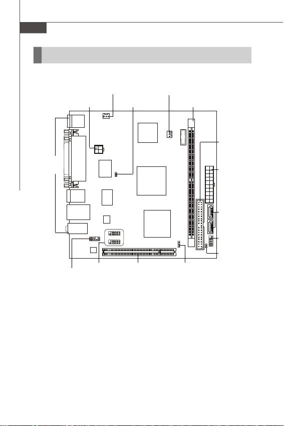
Quick Components Guide
SYS_FAN1, En-12 SYS_FAN2, En-12
JPW1, En-7
JCI1, En-13
DDR2 DIMMs, En-5
IDE1, En-10
Back Panel,
En-8
ATX1, En-7
SATA, En-11
JFP1, En-13
JBR1, En-11
JUSB1~2,
PCI,
JBAT1,
JAUD1,
En-14
En-16
En-15
En-12
En-4
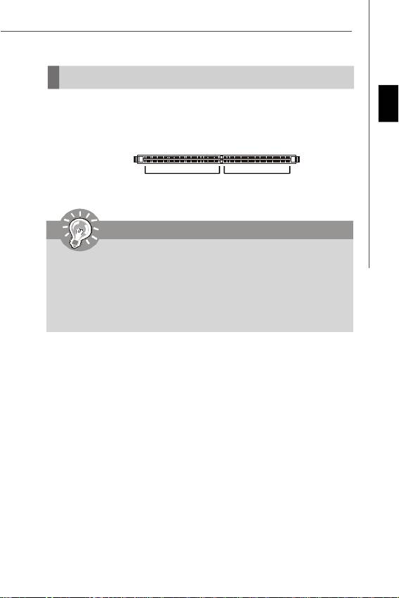
Memory
The DIMM slot is used for installing memory module.
For more information on compatible components, please visit http://global.msi.com.
English
tw/index.php?func=testreport
DDR2
240-pin, 1.8V
64x2=128 pin 56x2=112 pin
Important
-DDR2 memory module is not interchangeable with DDR and the DDR2 stan-
dard is not backwards compatible. You should always install DDR2 memory
module in the DDR2 DIMM slot.
- For more information on compatible components, please visit http://global.
msi.com.tw/index.php?func=testreport
- Due to the CPU limitation, the installed 667 MHz memory will be dropped to
533 MHz for system stability.
En-5
MS-7314 Mainboard
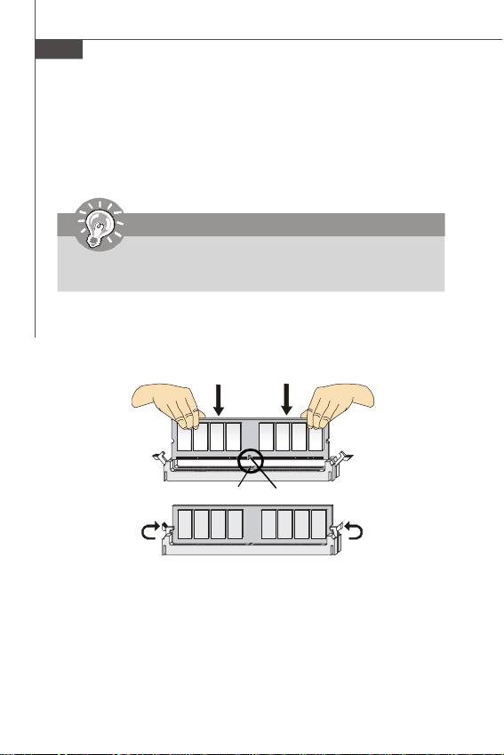
Installing Memory Modules
1. The memory module has only one notch on the center and will only fit in the right
orientation.
2. Insert the memory module vertically into the DIMM slot. Then push it in until the
golden finger on the memory module is deeply inserted in the DIMM slot. The plastic
clip at each side of the DIMM slot will automatically close when the memory module
is properly seated.
Important
You can barely see the golden finger if the memory module is properly inserted
in the DIMM slot.
3. Manually check if the memory module has been locked in place by the DIMM slot
clips at the sides.
Volt
Notch
En-6
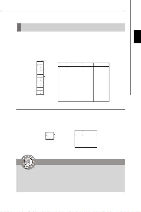
Power Supply
ATX 20-Pin Power Connector: ATX1
English
This connector allows you to connect to an ATX power supply. To connect to the ATX
power supply, make sure the plug of the power supply is inserted in the proper
orientation and the pins are aligned. Then push down the power supply firmly into the
connector.
Pin Definition
10
20
PIN SIGNAL
PIN SIGNAL
1 3.3V
11 3.3V
2 3.3V
12 -12V
3 GND
13 GND
4 5V
14 PS_ON
5 GND
15 GND
6 5V
16 GND
7 GND
17 GND
8 PW_OK
18 -5V
1
11
9 5V_SB
19 5V
ATX1
10 12V
20 5V
ATX 4-pin Power Connector: JPW1
This power connector is used to provide power to the CPU.
Pin Definition
1 3
PIN SIGNAL
JPW1
1 GND
2 GND
42
3 12V
4 12V
Important
1. For more information on compatible components, please visit http://global.
msi.com.tw/index.php?func=testreport
2. Make sure that all the connectors are connected to proper ATX power
supplies to ensure stable operation of the mainboard.
3. Power supply of 400 watts (and lower) is strongly recommended for system
stability.
En-7
MS-7314 Mainboard
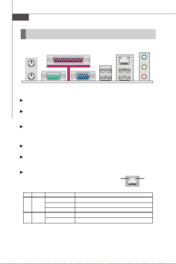
Back Panel
LAN
Parallel Port
Mouse
Line-In
Line-Out
Keyboard
Serial Port USB Port
USB Port
Mic
VGA Port
Mouse/Keyboard
®
®
The standard PS/2
mouse/keyboard DIN connector is for a PS/2
mouse/keyboard.
Parallel Port
A parallel port is a standard printer port that supports Enhanced Parallel Port (EPP)
and Extended Capabilities Parallel Port (ECP) mode.
Serial Port
The serial port is a 16550A high speed communications port that sends/ receives 16
bytes FIFOs. You can attach a serial mouse or other serial devices directly to the
connector.
VGA Port
The DB15-pin female connector is provided for monitor.
USB Port
The USB (Universal Serial Bus) port is for attaching USB devices such as keyboard,
mouse, or other USB-compatible devices.
LAN
The standard RJ-45 LAN jack is for connection to the
GreenYellow
Local Area Network (LAN). You can connect a network
cable to it.
LED Color LED State Condition
Off LAN link is not established.
Left Yellow On (steady state) LAN link is established.
On (brighter & pulsing)The computer is communicating with another computer on the LAN.
Right
Green Off 10 Mbit/sec data rate is selected.
On 100 Mbit/sec data rate is selected.
En-8

Audio Ports
These audio connectors are used for audio devices. It is easy to differentiate be-
tween audio effects according to the color of audio jacks.
Line-In (Blue) - Line In is used for external CD player, tapeplayer or
English
other audio devices.
Line-Out (Green) - Line Out, is a connector for speakers or headphones.
Mic (Pink) - Mic, is a connector for microphones.
Important
The Realtek audio provided to offer support for 5.1-channel audio operation
and can turn rear audio connectors from 2-channel to 4-/ 5.1-channel audio.
En-9
MS-7314 Mainboard
Connectors
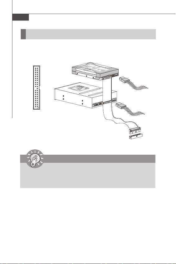
IDE Connector: IDE1
This connector supports IDE hard disk drives, optical disk drives and other IDE devices.
IDE1
Important
If you install two IDE devices on the same cable, you must configure the
drives separately to master / slave mode by setting jumpers. Refer to IDE
device’s documentation supplied by the vendors for jumper setting
instructions.
En-10
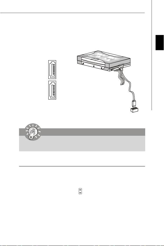
Serial ATA Connector: SATA1~2
This connector is a high-speed Serial ATA interface port. Each connector can con-
nect to one Serial ATA device.
English
SATA1
SATA2
Important
Please do not fold the Serial ATA cable into 90-degree angle. Otherwise,
data loss may occur during transmission.
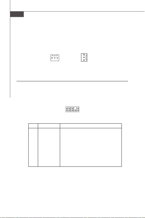
Speaker Connector: JBR1
This connector connects to the speaker of the case.
SPK-
2
SPK+
1
JBR1
En-11
MS-7314 Mainboard
Fan Power Connectors: SYS_FAN1/ SYS_FAN2
The fan power connectors support system cooling fan with +12V. When connecting
the wire to the connectors, always note that the red wire is the positive and should
be connected to the +12V; the black wire is Ground and should be connected to GND.
SENSOR
+12V
GND
SENSOR
+12V
GND
SYS_FAN2SYS_FAN1
Front Panel Audio Connector: JAUD1
This connector allows you to connect the front panel audio and is compliant with
®
Intel
Front Panel I/O Connectivity Design Guide.
JAUD1
2
10
1
9
Pin Definition
PIN SIGNAL DESCRIPTION
1 MIC_L Microphone - Left channel
2 GND Ground
3 MIC_R Microphone - Right channel
4 NC
5 LINE out_R Analog Port - Right channel
6 MIC_JD Jack detection return from front panel microphone JACK1
7 Front_JD Jack detection sense line from the High Definition Audio CODEC
jack detection resistor network
8 NC No control
9 LINE out_L Analog Port - Left channel
10 LINEout_JD Jack detection return from front panel JACK2
En-12
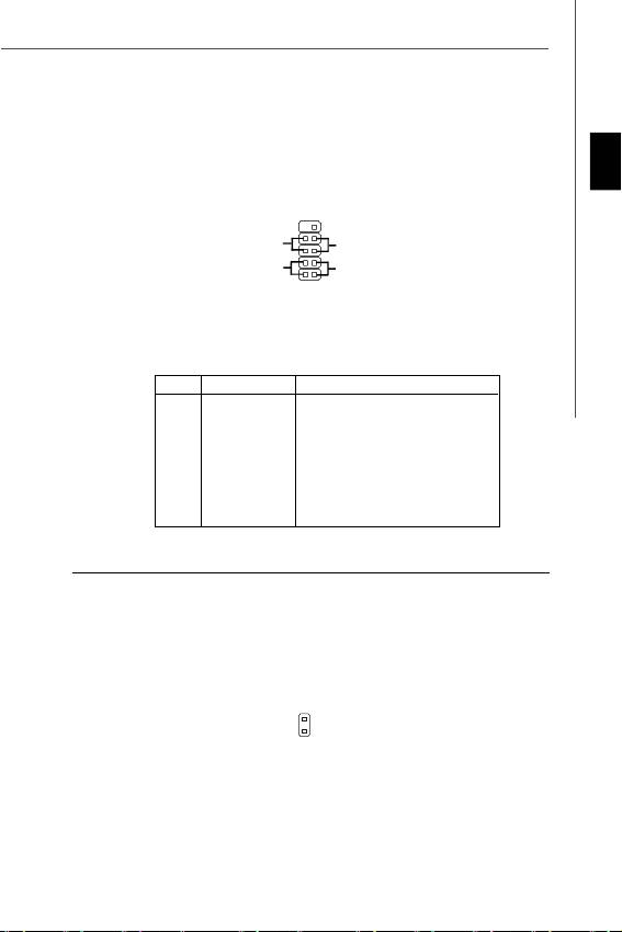
Front Panel Connector: JFP1
This connector is for electrical connection to the front panel switches and LEDs. The
®
JFP1 is compliant with Intel
Front Panel I/O Connectivity Design Guide.
English
910
Power
-
+
Reset
Switch
+
-
Switch
Power
-
HDD
LED
+
LED
2
1
JFP1
JFP1 Pin Definition
PIN SIGNAL DESCRIPTION
1 HD_LED + Hard disk LED pull-up
2 FP PWR/SLP MSG LED pull-up
3 HD_LED - Hard disk active LED
4 FP PWR/SLP MSG LED pull-up
5 RST_SW - Reset Switch low reference pull-down to GND
6 PWR_SW + Power Switch high reference pull-up
7 RST_SW + Reset Switch high reference pull-up
8 PWR_SW - Power Switch low reference pull-down to GND
9 RSVD_DNU Reserved. Do not use.
Chassis Intrusion Connector: JCI1
This connector connects to the chassis intrusion switch cable. If the chassis is
opened, the chassis intrusion mechanism will be activated. The system will record
this status and show a warning message on the screen. To clear the warning, you
must enter the BIOS utility and clear the record.
CINTRU
1
GND
2
JCI1
En-13
MS-7314 Mainboard
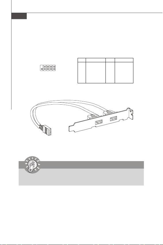
Front USB Connector: JUSB1~2
®
These connectors, compliant with Intel
I/O Connectivity Design Guide, is ideal for
connecting high-speed USB interface peripherals such as USB HDD, digital cameras,
MP3 players, printers, modems and the like.
Pin Definition
PIN SIGNAL PIN SIGNAL
1 VCC 2 VCC
9
1
3 USB0- 4 USB1-
10
2
5 USB0+ 6 USB1+
JUSB1/2
7 GND 8 GND
9 Key (no pin) 10 NC
USB 2.0 Bracket
(optional)
Important
Note that the pins of VCC and GND must be connected correctly to avoid
possible damage.
En-14
Jumper
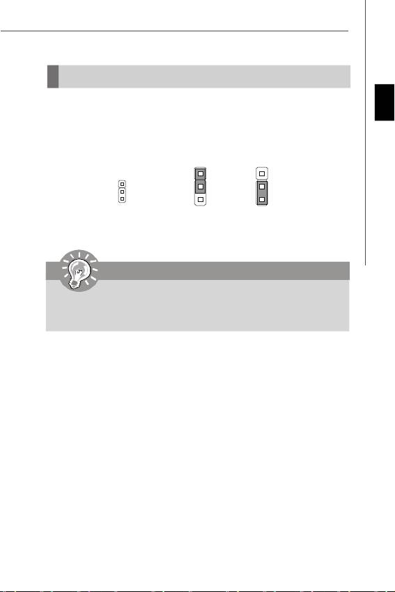
Clear CMOS Jumper: JBAT1
English
There is a CMOS RAM onboard that has a power supply from an external battery to
keep the data of system configuration. With the CMOS RAM, the system can auto-
matically boot OS every time it is turned on. If you want to clear the system configuration,
set the jumper to clear data.
1
1
1
3
3
JBAT1
Keep Data Clear Data
Important
You can clear CMOS by shorting 2-3 pin while the system is off. Then return
to 1-2 pin position. Avoid clearing the CMOS while the system is on; it will
damage the mainboard.
En-15
MS-7314 Mainboard
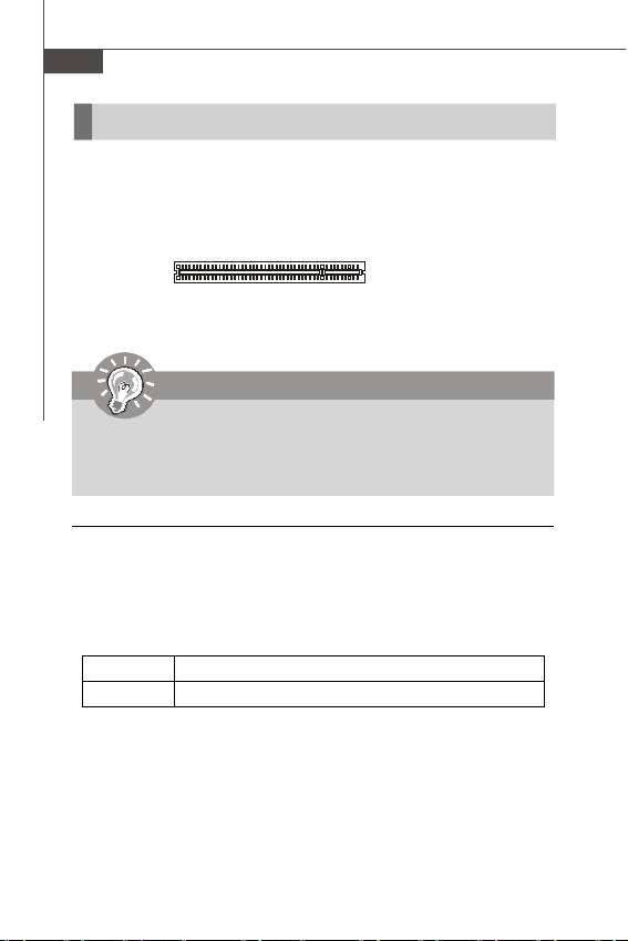
Slot
PCI (Peripheral Component Interconnect) Slot
The PCI slot supports LAN card, SCSI card, USB card, and other add-on cards that
comply with PCI specifications.
32-bit PCI Slot
Important
When adding or removing expansion cards, make sure that you unplug the
power supply first. Meanwhile, read the documentation for the expansion card
to configure any necessary hardware or software settings for the expansion
card, such as jumpers, switches or BIOS configuration.
PCI Interrupt Request Routing
The IRQ, acronym of interrupt request line and pronounced I-R-Q, are hardware lines
over which devices can send interrupt signals to the microprocessor. The PCI IRQ
pins are typically connected to the PCI bus pins as follows:
Order 1 Order 2 Order 3 Order 4
PCI Slot 1 INT A# INT B# INT C# INT D#
En-16
BIOS Setup
This chapter provides basic information on the BIOS Setup program and allows you
to configure the system for optimum use. You may need to run the Setup program
English
when:
* An error message appears on the screen during the system booting up, and requests
you to run BIOS SETUP.
* You want to change the default settings for customized features.
Important
1.The items under each BIOS category described in this chapter are under
continuous update for better system performance. Therefore, the description
may be slightly different from the latest BIOS and should be held for reference
only.
2.Upon boot-up, the 1st line appearing after the memory count is the BIOS
version. It is usually in the format:
A7314IMS V4.0 110208 where:
1st digit refers to BIOS maker as A = AMI, W = AWARD, and P = PHOENIX.
2nd - 5th digit refers to the model number.
6th refers to the Chipset vender as A = AMD, I = Intel, V = VIA, N = Nvidia, U =
ULi.
7th - 8th digit refers to the customer as MS = all standard customers.
V4.0 refers to the BIOS version.
110208 refers to the date this BIOS was released.
En-17

MS-7314 Mainboard
Entering Setup
Power on the computer and the system will start POST (Power On Self Test) process.
When the message below appears on the screen, press <DEL> key to enter Setup.
Press DEL to enter SETUP
If the message disappears before you respond and you still wish to enter Setup,
restart the system by turning it OFF and On or pressing the RESET button. You may
also restart the system by simultaneously pressing <Ctrl>, <Alt>, and <Delete> keys.
Getting Help
After entering the Setup menu, the first menu you will see is the Main Menu.
Main Menu
The main menu lists the setup functions you can make changes to. You can use the
arrow keys (↑↓ ) to select the item. The on-line description of the highlighted setup
function is displayed at the bottom of the screen.
Sub-Menu
If you find a right pointer symbol (as shown in the right view)
appears to the left of certain fields that means a sub-menu
containing additional options can be launched from this field.
You can use control keys (↑↓ ) to highlight the field and press <Enter> to call up the
sub-menu. Then you can use the control keys to enter values and move from field to
field within a sub-menu. If you want to return to the main menu, just press <Esc >.
General Help <F1>
The BIOS setup program provides a General Help screen. You can call up this screen
from any menu by simply pressing <F1>. The Help screen lists the appropriate keys
to use and the possible selections for the highlighted item. Press <Esc> to exit the
Help screen.
En-18
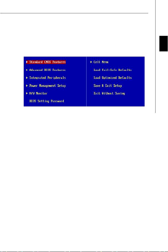
The Main Menu
®
®
Once you enter AMI
or AWARD
BIOS CMOS Setup Utility, the Main Menu will appear
on the screen. The Main Menu allows you to select from the setup functions and two
exit choices. Use arrow keys to select among the items and press <Enter> to accept
English
or enter the sub-menu.
Standard CMOS Features
Use this menu for basic system configurations, such as time, date etc.
Advanced BIOS Features
Use this menu to setup the items of special enhanced features.
Integrated Peripherals
Use this menu to specify your settings for integrated peripherals.
Power Management Setup
Use this menu to specify your settings for power management.
H/W Monitor
This entry shows your PC health status.
BIOS Setting Password
Use this menu to set the Password.
Cell Menu
Use this menu to specify your settings for frequency/voltage control and overclocking.
Load Fail-Safe Defaults
Use this menu to load the default values set by the BIOS vendor for stable system
performance.
Load Optimized Defaults
Use this menu to load the default values set by the mainboard manufacturer specifically
for optimal performance of the mainboard.
Save & Exit Setup
Save changes to CMOS and exit setup.
Exit Without Saving
Abandon all changes and exit setup.
En-19
MS-7314 Mainboard
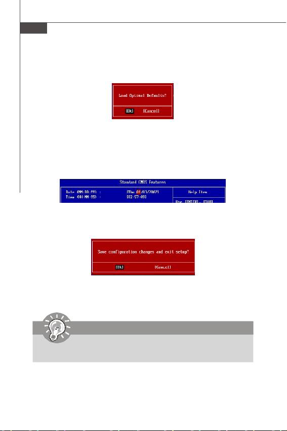
When enter the BIOS Setup utility, follow the processes below for general use.
1. Load Optimized Defaults : Use control keys (↑↓) to highlight the Load
Optimized Defaults field and press <Enter> , a message as below appears:
Select [Ok] and press Enter to load the default settings for optimal system
performance.
2. Setup Date/ Time : Select the Standard CMOS Features and press <Enter> to
enter the Standard CMOS Features-menu. Adjust the Date, Time fields.
3. Save & Exit Setup : Use control keys (↑↓) to highlight the Save & Exit Setup
field and press <Enter> , a message as below appears:
Select [Ok] and press Enter to save the configurations and exit BIOS Setup utility.
Important
The configuration above are for general use only. If you need the detailed
settings of BIOS, please read the manual in English version on MSI website.
En-20
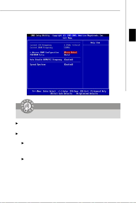
4. Cell Menu Introduction : This menu is for advanced user who want to overclock
the mainboard.
English
Important
Change these settings only if you are familiar with the chipset.
Current CPU / DRAM Frequency
These items show the current clocks of CPU and Memory speed. Read-only.
Advance DRAM Configuration
Press <Enter> to enter the sub-menu.
Configure DRAM Timing by SPD
Setting to [Auto] enables DRAM timings and the following related items automatically
to be determined by BIOS based on the configurations on the SPD (Serial Presence
Detect) EEPROM on the DRAM module.
CAS# Latency (CL)
When the Configure DRAM Timing by SPD sets to [Manual], the field is
adjustable. This controls the CAS latency, which determines the timing delay (in
clock cycles) before SDRAM starts a read command after receiving it.
En-21

MS-7314 Mainboard
tRCD
When the Configure DRAM Timing by SPD sets to [Manual], the field is
adjustable. When DRAM is refreshed, both rows and columns are addressed
separately. This setup item allows you to determine the timing of the transition
from RAS (row address strobe) to CAS (column address strobe). The less the
clock cycles, the faster the DRAM performance.
tRP
When the Configure DRAM Timing by SPD sets to [Manual], this field is
adjustable. This setting controls the number of cycles for Row Address Strobe
(RAS) to be allowed to precharge. If insufficient time is allowed for the RAS to
accumulate its charge before DRAM refresh, refresh may be incomplete and
DRAM may fail to retain data. This item applies only when synchronous DRAM is
installed in the system.
tRAS
When the Configure DRAM Timing by SPD sets to [Manual], this field is
adjustable. This setting determines the time RAS takes to read from and write to
memory cell.
FSB/DRAM Ratio
This item will allow you to adjust the ratio of FSB to memory.
Auto Disable DRAM/PCI Frequency
When set to [Enabled], the system will remove (turn off) clocks from empty DIMM and
PCI slots to minimize the electromagnetic interference (EMI).
Spread Spectrum
When the mainboard’s clock generator pulses, the extreme values (spikes) of the
pulses create EMI (Electromagnetic Interference). The Spread Spectrum function
reduces the EMI generated by modulating the pulses so that the spikes of the pulses
are reduced to flatter curves. If you do not have any EMI problem, leave the setting at
Disabled for optimal system stability and performance. But if you are plagued by EMI,
set to Enabled for EMI reduction. Remember to disable Spread Spectrum if you are
overclocking because even a slight jitter can introduce a temporary boost in clock
speed which may just cause your overclocked processor to lock up.
Important
1.If you do not have any EMI problem, leave the setting at [Disabled] for
optimal system stability and performance. But if you are plagued by EMI,
select the value of Spread Spectrum for EMI reduction.
2.The greater the Spread Spectrum value is, the greater the EMI is reduced,
and the system will become less stable. For the most suitable Spread
Spectrum value, please consult your local EMI regulation.
3.Remember to disable Spread Spectrum if you are overclocking because
even a slight jitter can introduce a temporary boost in clock speed which
may just cause your overclocked processor to lock up.
En-22

Software Information
Take out the Driver/Utility CD that is included in the mainboard package, and place it
into the CD-ROM drive. The installation will auto-run, simply click the driver or utility
English
and follow the pop-up screen to complete the installation. The Driver/Utility CD con-
tains the:
Driver menu - The Driver menu shows the available drivers. Install the driver by your
desire and to activate the device.
Utility menu - The Utility menu shows the software applications that the mainboard
supports.
WebSite menu- The WebSite menu shows the necessary websites.
Important
Please visit the MSI website to get the latest drivers and BIOS for better system
performance.
En-23
Table of contents
- Wind Board 330 User’s Guide English
- Wind Board 330
- Wind Board 330 Guide d’utilisation
- Wind Board 330 Руководство пользователя
