Alexika RET control-visc – page 2
Manual for Alexika RET control-visc
21
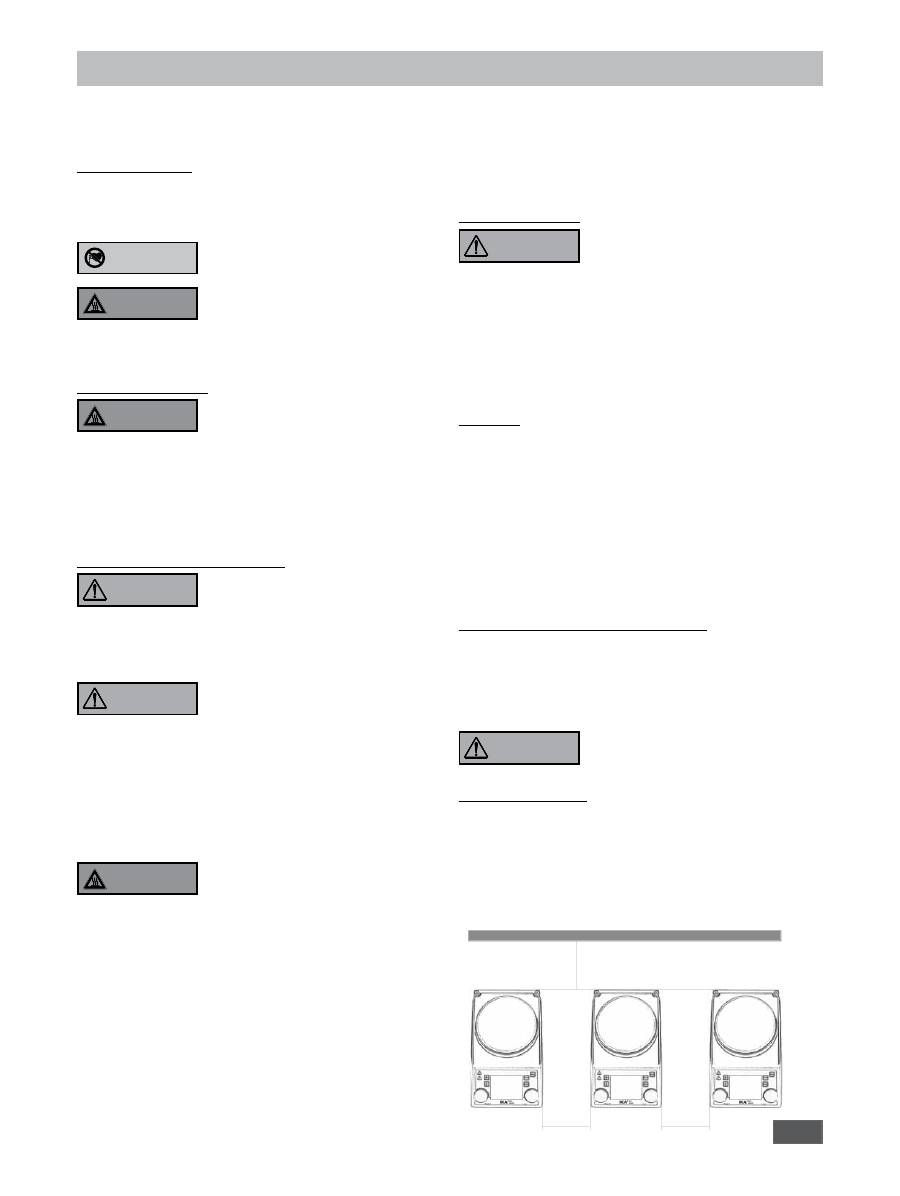
>100 mm
>100 mm
>100 mm
Safety instructions
•
Please read the instruction manual in full before use and
follow the safety instructions.
• Keep the instruction manual in a place where it can be accessed
easily.
General instructions
•
Ensure that only trained staff use the device.
•
Be sure to comply with all safety instructions, directives and all
matters of health, safety and accident prevention in the workplace.
• The plug must be earthed (grounded contact).
Caution - magnetism!
Beware of possible effects from the
magnetic field (pacemakers, data media,
etc.).
Burns hazard!
Exercise caution when touching housing
components and the heating plate. The
heating plate can reach temperatures of up to 320°C. Watch for
residual heat after appliance has been switched off.
The device should only be transported once it has cooled!
Device configuration
Do
not
operate the device in explosive
atmospheres, in the presence of hazard-
ous materials or under water.
• Install the device on a flat, stable, clean, non-slip, dry and fire-
resistant surface.
• The device feet must be clean and undamaged.
• The power supply cable and cables to the external sensors must
not be allowed to come into contact with the heated mounting
plate.
• Prior to each use, always check the device and accessories for
damage. Never use damaged parts.
Permissible media / Contamination / Side reactions
Caution!
Only media whose flashpoint
lies above the set safety temperature
limit (50°C - 380°C) may be processed
or heated with this device.
The set safety temperature limit must be at least 25°C below the
flashpoint of the medium in use.
Pay attention to the risks associated
with:
- flammable materials
- flammable media with low steam pressure
- glass breakage
- incorrect vessel size
- overfilling of medium
- unstable vessel.
• Only process pathogenic materials in closed vessels under a suit
-
able extractor hood. Please contact
IKA
®
if you have any ques-
tions.
Only work with media for which the en-
ergy input during processing is harmless.
This also needs to take into account
other sources of energy such as, for example, light irradiation.
• At high speeds the mounting plate is liable to warming, even if
the device is not in heating mode.
• Bear in mind the possibility of contamination or unwanted chem
-
ical reactions.
• There is the possibility that friction from rotating accessory parts
can result in contamination of the medium being processed.
• Bear in mind the following when using PTFE-coated magnetic
rods:
Chemical reactions of PTFE occur in contact with molten
or solute alkali metals and alkaline earth metals as well as with
fine powders of metals in groups 2 and 3 of the periodic table
ATTENTION
DANGER
at temperatures above 300-400°C. Only elementary fluorine,
chlorine trifluoride and alkali metals attack it; halogenated hy-
drocarbons have a reversible swelling effect
.
(Source: Römpp “Chemie-Lexikon” and “Ullmann” Vol. 19)
• Only glass-coated magnetic rods should be used in conjunction
with solute alkali metals or alkaline earth metals or at tempera-
tures above 250°C.
Performing trials
Always
wear personal protective
equipment in accordance with the hazard
class of the media being worked with.
Otherwise there is the risk of the following:
- spraying and evaporation of liquids
- ejection of parts
- release of toxic or inflammable gases.
• If any of the following happens, reduce the speed:
- medium sprays out of vessel due to excessive speed
- process is not smooth
- vessel moves around on the mounting plate.
Accessories
• Safe operation can only be ensured when working with acces
-
sories as described in the “
Accessories
” section.
• Only put together accessories with the power supply cable dis
-
connected.
• Refer to the operating instructions for the accessories.
• Immerse the external temperature sensor (PT1000, ETS-D, etc.)
at least 20 mm into the medium.
• The PT1000 external temperature sensor must always be inside
the medium.
• Accessories must be connected securely to the device and must
not come loose on their own. The centre of gravity of the device
must be located within the mounting plate.
Power supply / switching off the device
• The specified settings on the rating plate must coincide with the
actual power supply.
• The plug for the power supply connection must be easy to access
and remove.
• The device is only disconnected from the power supply when the
power or device plug is removed.
After an interruption to the power sup-
ply, the device starts up again in Mode B.
Protection of the device
• The device must only be opened by trained, skilled personnel.
• Do not cover the device, even partially, with elements such as
metallic plates or sheets otherwise it may overheat.
• Avoid knocks or impact to the device or accessories.
• Ensure the mounting plate remains clean.
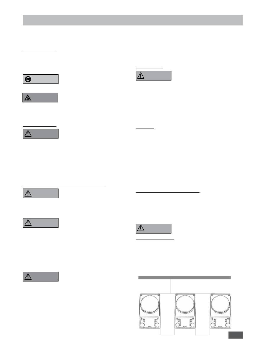
•
Observe minimum distances between devices, between the device
and the wall, and above and below the device (min. 800 mm).
WARNING
DANGER
WARNING
WARNING
DANGER
WARNING
22
Unpacking
• Unpacking
- Unpack the device carefully
- Any damage should be notified immediately to the shipping
agent (post office, railway network or transport company)
• Scope of delivery
- RET control visc heated magnetic stirrer
- Power supply cable
- Operating instructions
- Screwdriver (safety circuit)
- USB cable
- Protective cover:
H104
- Magnetic rods:
IKAFLON
30
and
40
mm
- Temperature sensor:
PT 100.70
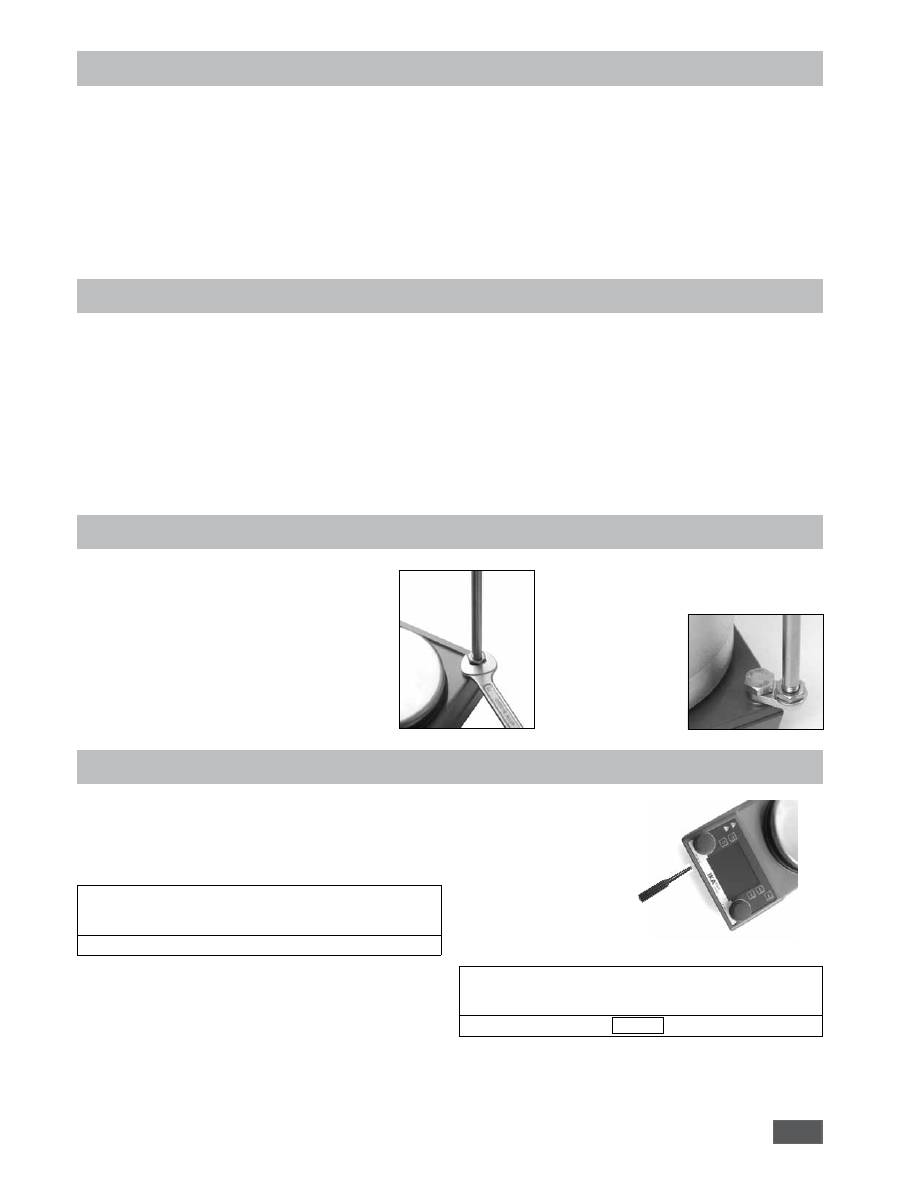
Correct use
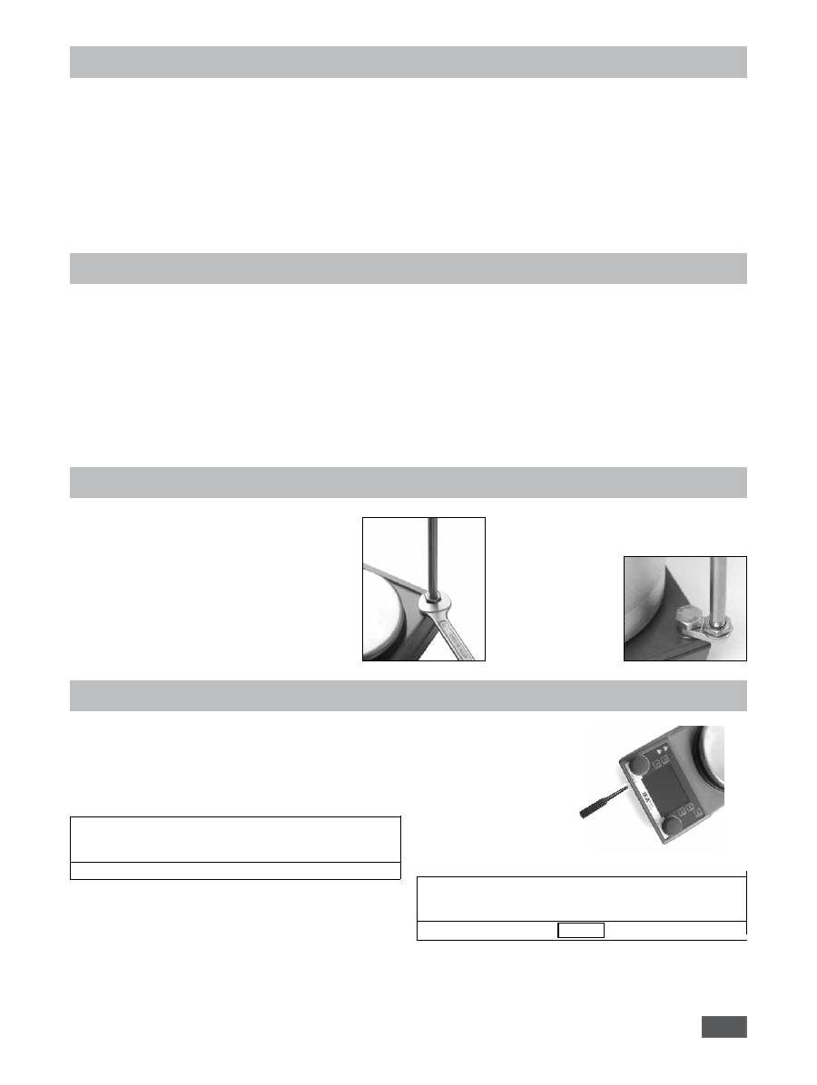
Assembling the support rod
Note:
When using bath attachments with a diameter
over 180 mm, use sup-
port rod H 16 V in con-
junction with an H
16.1 extension.
The set safety temperature is displayed permanently (
7
).
Factory settings: approx. 380°C
Range: 50 - 380°C
Setting the safety temperature limit
a
Set the main switch
(A)
to the ON position
a
Set the temperature limit using the screwdriver (supplied)
at point
(B)
i
The set value is displayed on the screen
The adjustable maximum heating plate temperature of 340°C is
at least 10°C under the set safety temperature limit.
Caution: the set safety temperature limit must always be
at least 25°C below the flashpoint of the medium in use.
Functional test: safety circuit switch-off
a
Heat the device to a temperature of over 50°C.
a
Set the safety temperature limit as far to the left as possible (50°C)
and set the main switch (A) to the ON position
i
The display will show: Err 25
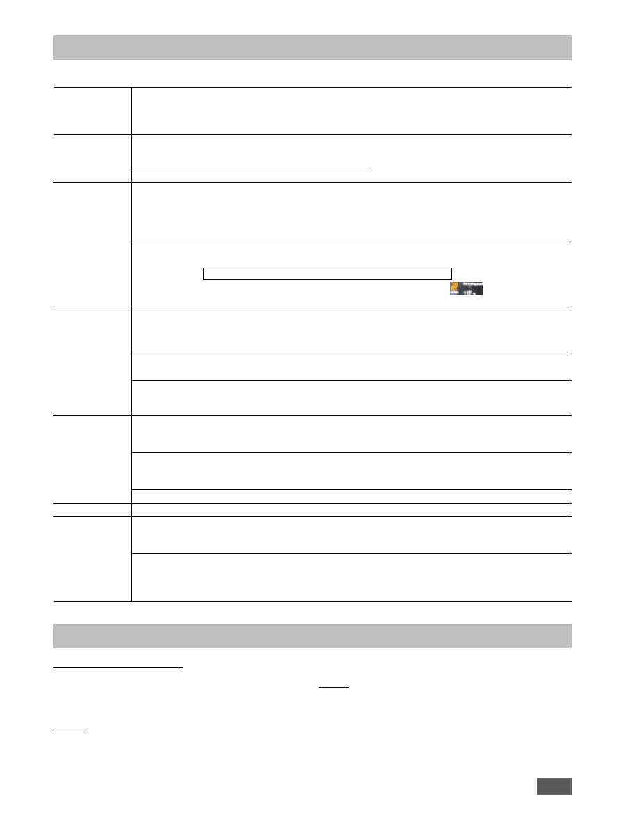
Setting the safety temperature limit
Be careful not to turn the adjustment screw too far to the left or
right or this will damage the potentiometer.
• Use
- for mixing and/or heating liquids.
• Area of use (only indoors)
- laboratories
- schools
- pharmacies
- universities
The device is suitable for use in all areas apart from domestic areas
and areas directly connected to a low-voltage supply which also
serves domestic areas.
The safety of the user cannot be guaranteed if the device is used
in conjunction with accessories which are not supplied or recom-
mended by the manufacturer, if the device is used contrary to the
intended purpose against the manufacturer’s instructions or if the
device itself or PCB has been subjected to modifications by third
parties.
•
Remove the threaded plug
(P)
• Remove the protective cap from the support rod
• Place the washer between the housing and the nut
• Screw in the support rod manually until it cannot be
tightened further
• Tighten the nut using an SW17 open-end spanner
• Assemble the accessories using a boss head clamp
23
Remove the protective film from the mounting plate before use! The “Back” menu key is used to change between menu items.
Start-up
Stirring
Heating
Connecting an ex-
ternal thermometer
(directtemperature
control in the me-
dium)
Weighing
pH measurement
Timer
F
Set the main switch (A) to the OFF position
F
Insert the power supply cable into the mains socket (K)
F
Set the main switch (A) to the ON position
a
Standard mode A is selected (see “Operating modes”)
F
Set the speed using the rotary knob (D)
a
The set value is shown on the display (F)
F
Press the rotary knob (D) to start the stirring function
i
a
The symbol (16) appears when the motor is active
F
Set the safety temperature limit (see “Setting the safety temperature limit”)
F
Set the target temperature using the rotary knob (C)
a
The set value is shown on the display (J)
F
Set the temperature control mode (see “Setting the temperature control mode”)
F
Press the rotary knob (C) to start the heating function
The target and current temperature are shown permanently on the display (J):
i
a
When the heating function is switched on, the heating symbol (4) is displayed
The maximum adjustable heating plate temperature setting is 340°C
i
a
Whenever the mounting plate is at a temperature above 50°C, the display (J) shows and the current tem-
perature is shown, even if the device is switched off.
F
Set the main switch (A) to the OFF position
F
Connect the safety contact thermometer compliant with DIN 12878 Class 2 or temperature sensor PT 100 (individual
sensor) or PT1000 (double sensor) to socket (L)
F
Set the main switch (A) to the ON position
i
Temperature sensor PT 100
a
The current temperature (5) shown on the display (J) corresponds to the tempera-
ture of the medium. The “Probe” symbol (11) lights up.
i
Temperature sensor PT 1000
a
The current temperature (5) for the temperature sensor shown on the display (J)
corresponds to the temperature of the medium. The “External temperature probe”
symbol (11) appears. The temperature of the carrier fluid (3) is also displayed.
F
Press the (G) key
F
Wait until the system is stable (once the system is stable, a “g” appears after the digit 0).
F
Place the weight in the centre of the heating plate and wait until the system is stable once again.
i
a
The maximum display range is up to 2,000 g
a
The weighing range is max. 5,000 g
a
It is only possible to use the weighing mode when the heating or stirring functions are not active
i
a
The weighing module can be calibrated (see section entitled “Calibrating the weighing module”)
a
see section entitled “Calibration of the pH probe and pH measurement”
F
Press the (H) key
F
Set the time in hours, minutes and seconds by turning the knob (D) and confirm by pressing it; the timer function
starts to count down the remaining time once the heating or stirring function has started (see “Timer function”)
i
Once the timer reaches 0, the heating function is switched off, even if the motor has only just been started.
If the heating is activated during the timer sequence, only the heating is switched off, but the motor continues
to run (delay in boiling).
Operation
(brief instructions)
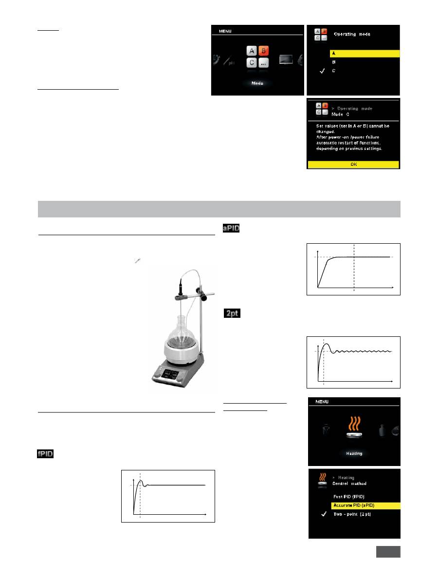
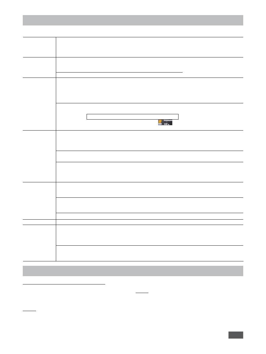
Setting the operating mode
Operating the device in A, B, or C
Factory setting: Mode A
The set mode is shown permanently on the display (10).
Mode A
All the settings are retained when the device is switched off or
disconnected from the mains. When the device is switched on,
the status of the stirring and heating functions is set to (OFF).
Mode B
All the settings are retained when the device is switched off or
disconnected from the mains. When the device is switched on,
the status of the stirring and heating functions is set to whatever
it was before the device was last switched off (ON or OFF).
24
Mode C
In this mode, the device can be used either with or without a
temperature sensor.
When the device is switched on using the main switch, the
stirring and heating functions are started in the last set status
and at the last set values. The set nominal values in operating
modes A and B cannot be modified.
Changing the operating mode
-
Scroll down to the “Mode” icon in the menu
-
Open the submenu by pressing the rotary knob (D)
-
Use the rotary knob (D) to select the desired mode and
confirm by pressing the rotary knob (D)
-
A short description of the operating mode is then shown
on the display
-
Confirm selection of the operating mode by pressing the
rotary knob (D) once more.
Functions
When using the PT100, the selected temperature control mode is
shown on the digital display by the
(11) symbol.
The target temperature (2) and the
current temperature (5) shown on
the display refer to the temperature
of the medium. The heating plate
temperature is limited by the set
safety temperature (7). The medium
temperature is controlled by means
of a microcontroller. The medium
temperature is measured by the PT100
temperature sensor and is heated
up as quickly as possible without
overshooting to the set temperature.
The microcontroller is capable of
adjusting automatically to the different
heating capacities of various vessels
and their contents. As a result, the heat
is distributed in an optimum fashion
with no temperature drift or ripples.
Regulation of the temperature of the medium
using PT100 temperature sensor
The user is able to set the device to three different methods
depending on their specific needs. The selected temperature
control method is displayed alongside the symbol (
11
).
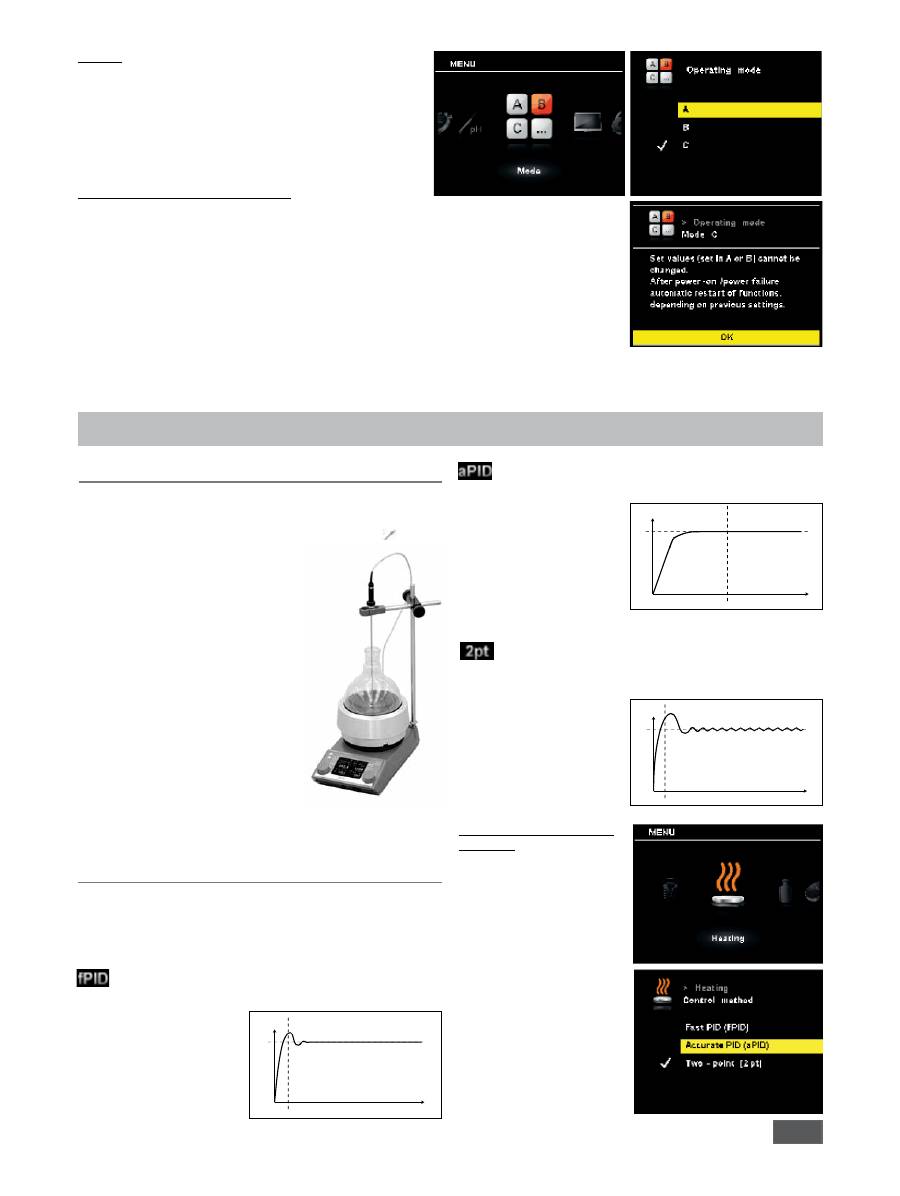
Control methods
Changing between the
control methods
-
Scroll down to the
“Heating” icon in the menu
-
Open the control method
submenu by pressing the
rotary knob (D)
-
Use the rotary knob (D) to
select the desired mode
and confirm by pressing
the rotary knob (D)
-
A short description of the
operating mode is then
shown on the display
-
Confirm selection by
pressing the rotary knob (D)
once more.
PID
: For use with very sensitive materials which need to be
handled carefully.
Advantages:
• very accurate warming
of the liquid
• no exceeding the target
temperature
Disadvantages:
• slow heating operating
T
Set
t
Fast PID:
combines the advantages of the PID and two-point
methods (very fast
heating and high
accuracy; possible
overheating).
Two-point
:
For media which is not too sensitive.
Advantages:
• Heating much more
rapid than
PID
Disadvantages:
• Possible overheating of
up to 10 K
T
Set
t
T
Set
t
25
Operation with the PT1000 double
sensor is indicated on the digital
display by the
symbol. One
temperature sensor is located in the
heat carrier fluid and the other is
located in the reaction medium. The
set target temperature (2) refers to
the temperature of the medium. The
higher temperature is automatically
attributed to the heat carrier fluid and
shown on the display as an additional
current temperature with the symbol
(3).
The actual temperature of the reaction
medium is shown as the current
temperature (5). The heating plate
temperature (and therefore the heat
carrier fluid temperature) are limited by the set heating plate
safety temperature limit (7). The reaction medium temperature
is limited by the set temperature limits (carrier fluid/reaction
temperature limit).
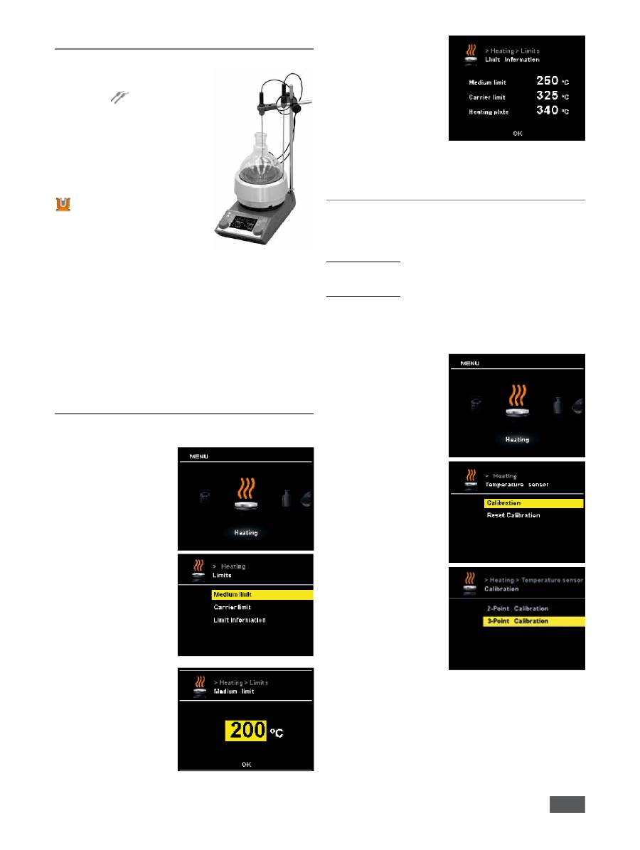
see section entitled “Limits”
Limits
In order to ensure that neither the reaction fluid nor the carrier
fluid overheat, the user can set separate temperature limits.
• Scroll to the “Heating” icon
in the menu
• Open the submenu by
pressing the rotary knob (D)
• Open the “Limits” submenu
followed by “Medium
limit” and then set the
temperature limit for the
reaction fluid.
• Confirm the set limit by
pressing the rotary knob (D)
• Open the “Carrier limit”
submenu and set the limit
temperature for the carrier
fluid.
• Confirm the set limit by
pressing the rotary knob (D)
Regulation of the temperature of the medium
using PT1000 double temperature sensor
• Open the “Limit
information” submenu.
All set limit temperatures,
including the safety limit
temperature of the heating
plate, as displayed on one
screen.
• Close the submenu by
pressing the rotary knob (D)
Calibrating the temperature sensor
In order to use tolerances to limit temperature deviations, the
user can calibrate the temperature sensor in conjunction with the
device.
2-point calibration:
Calibration using two temperatures
3-point calibration:
Most accurate way of calibrating the temperature sensor at three
different temperatures
Note:
A calibration carried out by the user is indicated on the display
with the symbol (11) shown in
red
.The calibration of the PT100
and PT1000.50 double
sensor are carried out
separately.
• Scroll to the “Heating” icon
in the menu
• Open the submenu by
pressing the rotary knob (D)
• Open the “Temperature
sensor” submenu and
then “Calibration”, finally
confirming by pressing the
rotary knob (D)
• Select either 2-point
calibration or 3-point
calibration and confirm by
pressing the rotary knob (D)
In this function, the speed can be pre-set before starting the
calibration.

26
g
g
Stirring bar breakaway
If the device detects that a stirring bar has broken away, the
stirring function is interrupted temporarily in order to pick up
the bar. The system then returns to the previously set speed.
When the system detects a bar breakaway, this is indicated with
a special symbol (
instead of symbol 16). If another stirring
bar breakaway occurs within the next 3 minutes (as long as the
target speed has not been modified), once the bar is recovered
the system only goes up to a speed of 100 rpm. In the case of
4 consecutive stirring bar breakaways -with less than 3 minutes’
normal speed between them - the error message ER 41 is
displayed. The speed is reduced to 200 rpm and the heating is
switched off.
In such cases, the testing conditions will need to be reconsidered.
NOTE:
The user is responsible for ensuring the suitability/function
of the stirring bar breakaway monitoring for the current
conditions: stirring bar, speed, vessel, medium, etc.
Stirring bar breakaway monitoring does not work if the
stirring bar already breaks away before the system has
reached the set target speed!
The higher the torque to be transferred, the more safely the
stirring bar breakaway monitoring works.
In a glass beaker with water, the stirring bar breakaway for a
bar from 40 mm (d=8 mm) upwards can be seen from 300 -
1,200 rpm. Longer stirring bars, larger bar surface areas, e.g.
Trika, or higher speeds increase the torque to be transferred.
• Scroll to the “Stirring” icon
in the menu
• Open the submenu by
pressing the rotary knob (D)
• Open the “Stirring bar
breakaway” submenu and
confirm by pressing the
rotary knob (D)
• Acknowledge the informa
-
tion screen displayed by
pressing the rotary knob (D)
g
Intermittent mode
Intermittent mode consists of regular, cyclical interruption of
the stirring function. The run time and interval can both be set.
When switching on the device, the time for each is displayed if
intermittent mode is activated
• Scroll to the “Stirring” icon
in the menu
• Open the submenu by
pressing the rotary knob (D)
• Open the “Interval”
submenu and confirm by
pressing the rotary knob (D)
• Enter the run time and stop
time using the rotary knob
(D) and finally confirm the
two by pressing it again.
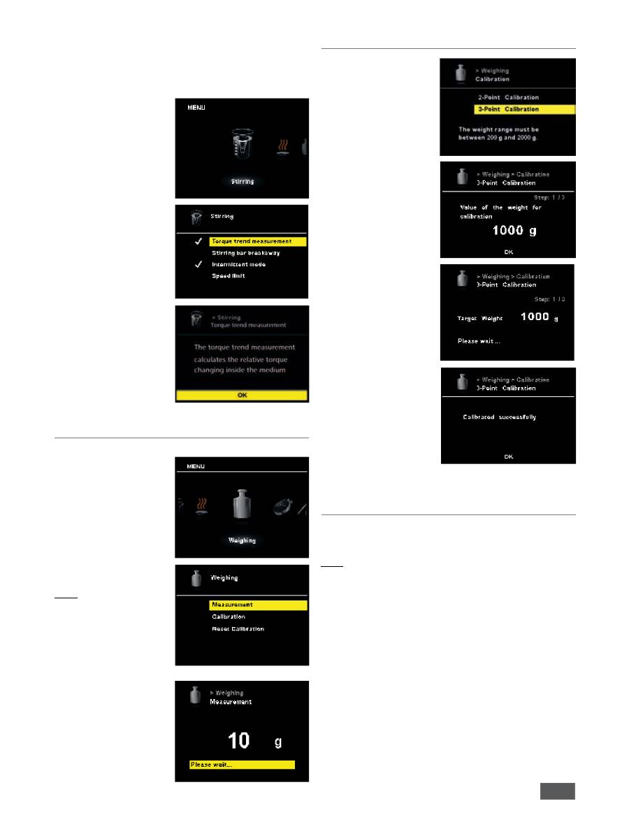
Torque trend measurement
The torque trend measurement is used to deduce the change in
viscosity of the reaction medium.
The devices are
not
designed to measure absolute viscosity. They
only measure and display the relative change in the viscosity of the
medium from a starting point specified by the user.
Once the speed of the motor and magnetic rod in the medium
have stabilised to the target speed, the viscosity measurement is
started at 100%.
Consequently, an increase in the measured torque trend is indicated
by a value > 100% and a reduction in values < 100%.
The value can always be reset to 100% by pressing the “Back” (F)
membrane key.
Note:
Torque trend measurement only works for a constant set
speed for the duration of the measurement.
As a result, intermittent mode cannot be used in
conjunction with torque trend measurement.
27
The current control variable is saved as the reference 100% ΔP
and shown on the digital display. The change in the viscosity is
then shown in %. Depending on whether the viscosity increases
or decreases, the percentage rises or falls above or below 100%
respectively.
• Scroll to the “Stirring” icon
in the menu
• Open the submenu by
pressing the rotary knob
(D)
• Open the “Torque trend
measurement” submenu
and confirm by pressing
the rotary knob (D)
• Acknowledge the informa
-
tion screen displayed
Weighing module
The weighing module is a function which allows the user to
perform simple weighing
tasks.
•
To start the weighing pro-
cess, press the (G) button
on the front membrane or
alternatively select Weig-
hing from the menu. Press
the rotary knob (D) to start
the weighing function.
Note:
The heating and stirring
functions must be deacti-
vated.
•
It may take several
moments for the system to
stabilise.
Once the system is stable,
a “g” will be shown
alongside the measured
value.
Weighing - Calibration
• Open the “Calibration”
submenu and confirm by
pressing the rotary knob
(D)
• Enter the calibration
weight and confirm by
pressing the rotary knob
(D)
• Place the calibration
weight on the mounting
plate and wait until the
device indicates that the
calibration process has
been completed.
This process needs to be
repeated two or three
times before closing cali-
bration mode
Once the calibration
process has been
completed successfully, the
weighing module is ready
for use.
Regularly re-calibrate the
device.
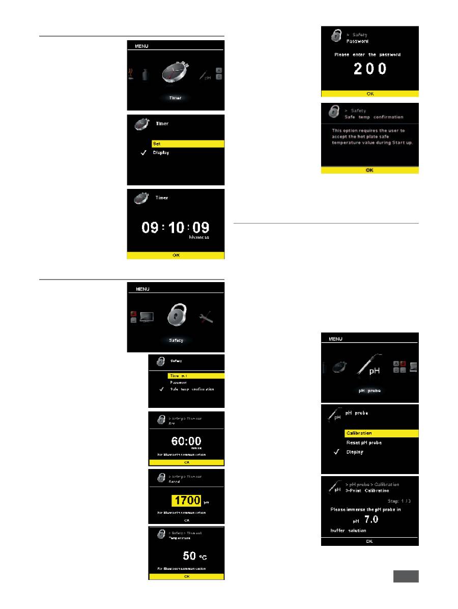
Timer / Counter
The Timer function allows the user to stop the heating process
after a certain time has lapsed. The Timer function can be set for
up to 99 hours, 59 minutes and 59 seconds.
Note:
The time starts to count down when starting both functions
(heating and/or stirring).
Once the heating function is activated, the timer function only
refers to heating. The stirring function continues to operate as
previously, thereby avoiding a delay in boiling in the liquid. The
motor is only switched off when the heating function is not
active. The stirring function is stopped if the heating function is
not started during the timer cycle and the time runs out.
NOTE:
By entering a value of
00:00:00
(hh:mm:ss), the counter is
activated. The counter shows the time elapsed during the current
experiment.
28
Setting of the timer
•
To start the timer function,
press the (H) button on
the front membrane or
alternatively select “Timer”
from the submenu.
The timer settings are
opened by clicking on
“Set”. The timer can be set
by turning the rotary knob
(D).
• Set the hours and press the
rotary knob (D)
• Set the minutes and press
the rotary knob (D)
• Set the seconds and press
the rotary knob (D)
The selected timer (count-
down) time is shown on
the display.
Safety settings
The user has several options
in the safety settings menu,
and the device functions can
be set according to the user’s
individual requirements.
•
To start, select “Safety” in
the submenu and confirm
by pressing the rotary knob
(D).
The “Timer” function is used to
define how long an interruption
in communications between the
magnetic stirrer and the wireless
controller box can be before there
is a reaction in the magnetic stirrer.
If the set time limit is exceeded,
the pre-selected temperature and
speed values become active.
Please refer to the separate in-
struction manual for the wireless
controller box for more details.
In the other menu items, the
user can enter limit values for the
temperature and speed.
•
Select “Password” from the
submenu and confirm by
pressing the rotary knob
(D).
Enter a combination of
digits as your password and
confirm by pressing the
rotary knob (D).
This information screen
informs the user that they
must confirm the hot
plate safe temperature
value when starting up the
device.
• Safety circuit confirmation
at device start-up: the hot
plate safe temperature
value must be confirmed by pressing the rotary knob (D).
pH measurement
The device has an integrated pH measuring feature for
determining the pH of different liquids.
The pH sensor must be calibrated before being used to attempt a
pH measurement.
The calibration is used to adjust the pH probe and the device
so that they work together correctly. As part of the process,
the neutral and pH gradient are specified for the measurement
chain. To complete the calibration, use pH
4, pH5 and pH7 buffer
solutions in accordance with DIN 19266.
Note:
a pH calibration can only be carried out with an inserted
temperature sensor.
• Scroll
down to the “pH
probe” icon in the menu
• Open the submenu by
pressing the rotary knob (D)
• Open the “Calibration”
submenu and confirm by
pressing the rotary knob (D)
• Place the pH probe and
temperature sensor in the
required buffer solution.
• Once the value is stable,
confirm it by pressing the
rotary knob (D).
• Follow the instructions on
the display and place the
pH probe and temperature
sensor in the next buffer
solution.
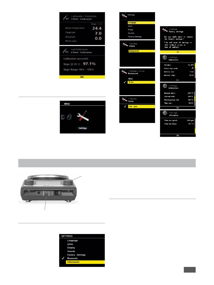
29
Confirm once more the
value displayed.
• In the case of a 3-point
calibration, a third buffer
solution must be used.
pH measurements can be
carried out once the cali-
bration has been comple-
ted successfully.
Please note:
the use of the temperature
sensor is limited by the
maximum permissible tem-
perature.
Ensure that the
temperature of the liquid does not exceed the maximum
permissible temperature.
Settings
The “Settings” menu can
be used to change how
the device operates in
accordance with the user’s
requirements.
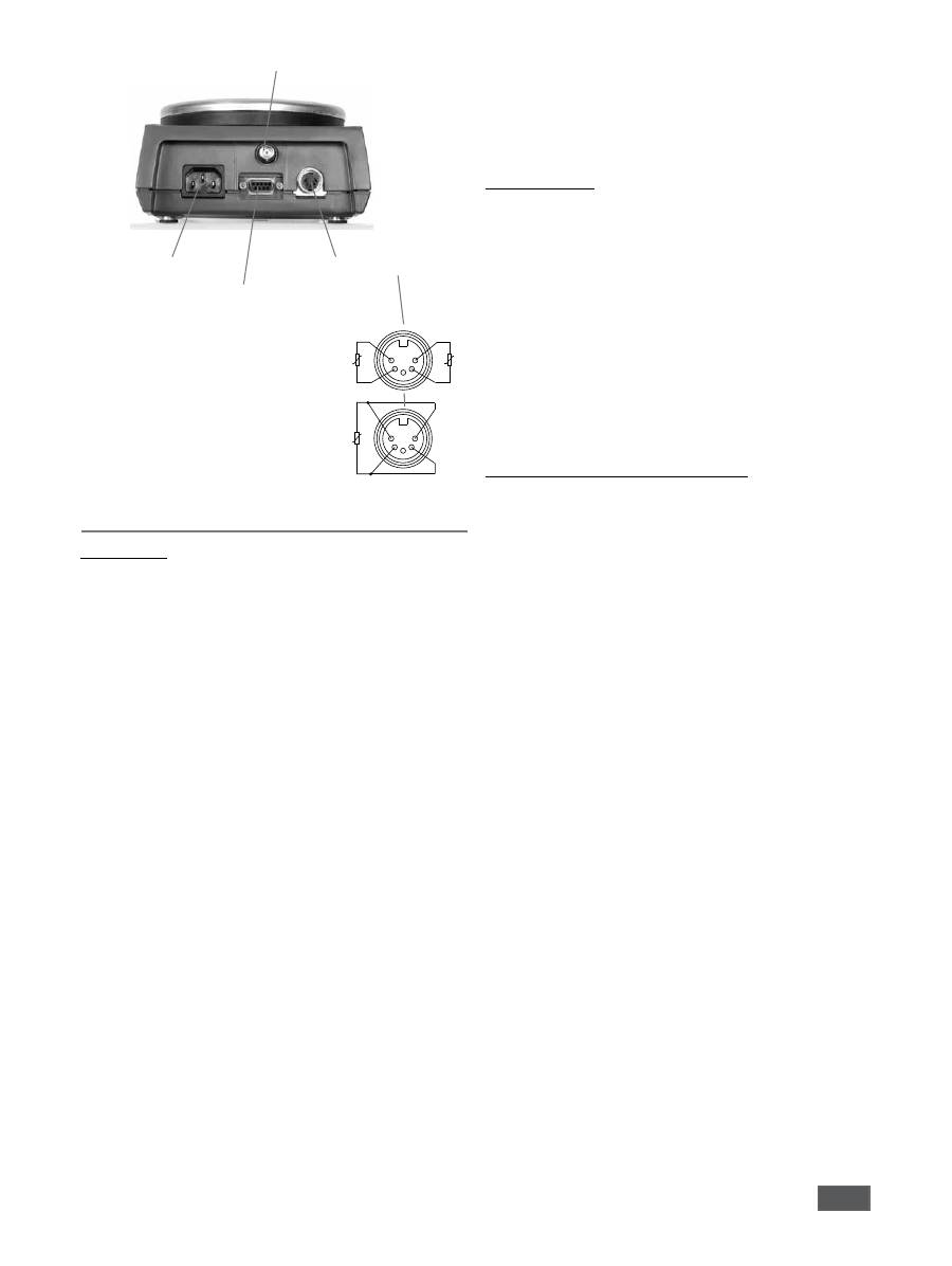
Connections and interfaces
Micro-USB
Bluetooth
Bluetooth
The device allows the user to establish a connection to a wireless
controller box.
The device can then be
operated via a wireless
controller box within a
range of 10 m (without
obstructions).
Establishing a connection
Please refer to the separate instruction manual for the wireless
controller box for more details.
30
Power supply
connection
PT 100 / PT 1000 plug
RS 232
BNC connector
(only for pH probe)
Pt1000-2
5
3
1
4
2
Pt1000-1
Pt100
5
3
1
4
2
9-pin connector
Serial RS 232 interface and USB
Configuration
The RS 232 serial interface can be used to operate the device
using a computer and a suitable user program (labworldsoft).
In order to increase safety when operating the RET using a
PC, a watchdog function can be activated which monitors
the continuous data flow (see section entitled: “Watchdog
function”).
• The functions of the interface circuit between the laboratory
device and the automation system are a selection from the
signals specified in the EIA standard RS232 as per DIN 66020
Part 1. The assignment of the different signals can be seen in
the image.
• Standard RS 232, corresponding to DIN 66259 Part 1 is valid
for the electronic characteristics of the interface circuits and
assignment of signal states.
• Transmission process: asynchronous character transmission in
start-stop operation.
• Transmission type: full duplex
• Character format: character composition according to data
format in DIN 66022 for start-stop operation. 1 start bit,
7 character bits, 1 parity bit (even), 1 stop bit.
• Transmission speed: 9,600 bit/s
• Data flow control: hardware handshake RTS/CTS
RTS: (PIN 7) LOW (positive voltage)
/ COMPUTER can transmit
RTS: (PIN 7) HIGH (negative voltage)
/ COMPUTER cannot transmit
CTS: (PIN 8) LOW (positive voltage)
/ COMPUTER ready-to-receive
CTS: (PIN 8) HIGH (negative voltage)
/ COMPUTER not ready-to-receive
• Access method: data transmission from the device to the
computer only occurs after a request from the computer.
Command syntax
The following points should be noted for the instruction set:
• Commands are generally sent from the computer (master) to
the lab device (slave).
• The lab device only responds to requests from the computer.
• Commands and parameters, as well as consecutive parameters,
must be separated by at least o n e space (code: hex 0x20).
• Each individual command including parameters and data and
all responses are completed with CR LF (code: hex 0x0D and
0x0A) and can have a maximum length of 10 characters.
• The dot is used for decimal separators in a floating-point value
(code: hex 0x2E).
The details given above generally comply with the recommendations
of NAMUR (NAMUR recommendations for the design of electrical
plug-in connectors for analogue and digital signals in laboratory
MSR devices. Rev. 1.1).
Summary of available NAMUR commands
Abbreviations used:
X,y = numbering parameter (integer)
m = variable value, integer
n = variable value, floating-point number
X = 1 medium temperature(external temperature sensor)
X = 2 hot plate temperature
X = 3 hot plate safety temperature
X = 4 speed
X = 5 viscosity trend
X = 7 heat transfer medium temperature
X = 80 pH value
X = 90 Weight value
X = 54 Error 5 response time in seconds (180 <= n <= 1200)
X = 55 Intermittent mode cycle time in seconds
( 10 <= n <= 600 )
X = 56 Intermittent mode, duration of interruption in seconds
( 5 <= n <= 60 )

31
NAMUR commands
Function
Display
(additional)
IN_NAME
Title request
IN_PV_X X=1;2;3;4;5;7;80;90 Current value reading
IN_SOFTWARE
Software ID number, date, version request
IN_SP_X
X=1;2;3;4;7;8;12;
42;54;55;56;
Set target value reading
IN_TYPE
Lab device identification request
OUT_NAME name
Output of identification name. (Max. 6 characters; default: IKAMAG)
OUT_SP_12@n
Setting WD safety limit temperature with set value echo
OUT_SP_42@n
Setting WD safety limit speed with set value echo
OUT_SP_X n
X=1;2;4;7;
54;55;56
Setting of target value to n
OUT_WD1@m
Watchdog mode 1: if event WD1 should occur, the heating and stirring functions are
switched off and ER 2 is displayed. Set watchdog time to m (20 - 1,500) seconds,
with watchdog time echo. This command launches the watchdog function and must
be transmitted within the set watchdog time.
OUT_WD2@m
Watchdog mode 2: if event WD2 should occur, the speed target value is changed to
the WD safety speed limit and the temperature target value is changed to the WD
safety temperature limit value. The warning WD is displayed. The WD2 event can be
reset with OUT_WD2@0 - this also stops the watchdog function. Set watchdog time
to m (20 - 1,500) seconds, with watchdog time echo. This command launches the
watchdog function and must be transmitted within the set watchdog time.
RESET
Switches off the device function.
START_X X=1;2;4;5;7
X=80; 90
Switching on of device - (remote) function
Activation of the previous watchdog function. If no target value is entered within
60 seconds, the (old function) heating is switched off.
Remote
STOP_X X=1;2;4;5;7
X=80; 90
Switching off of device - (remote) function The variables set with OUT_SP_X remain
saved. Includes command RMP_STOP.
Remote
32
“Watchdog” functions; monitoring of the serial data flow
If, once this function has been activated (see NAMUR commands),
there is no retransmission of the command from the computer
within the set time (“watchdog time”), the heating and stirring
functions are switched off in accordance with the set “watchdog”
function or are changed to the set target values.
The data transmission may be interrupted by, for example, a crash
in the operating system, a power failure in the PC or an issue with
the connection table between the computer and REC control.
“Watchdog” - mode 1
If there is an interruption in data communications (longer than
the set watchdog time), the heating and stirring functions are
switched off and ER 2 is displayed.
“Watchdog” - mode 2
If there is an interruption in data communications (longer than
the set watchdog time), the speed target value is changed to
the WD safety speed limit and the temperature target value is
changed to the WD safety temperature limit value. The warning
WD is displayed.
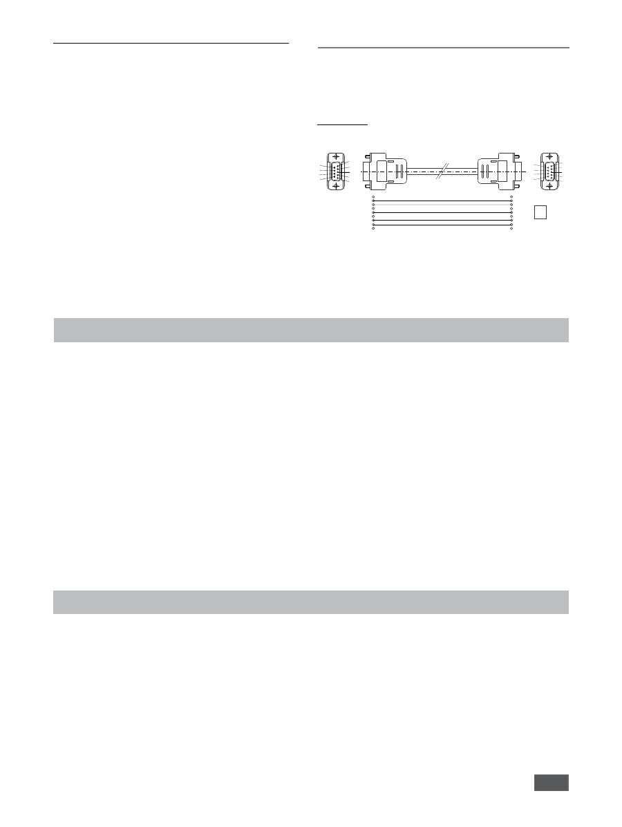
Connection possibilities between the RET control
and external devices
The following adapters and adapter cables are available from
IKA
®
for connecting the RET control to external devices.
PC 1.1 cable
The PC 1.1 cable is used to connect the 9-pin plug to a computer.
Accessories
Troubleshooting
The device will indicate that there is a fault by displaying an error
message “Er X” (see table) on the screen.
Heating will be switched off permanently (exception: WD - see
table).
The stirring function continues to operate at the pre-set speed if
there is a fault in the heating circuit (exception: WD - see table).
In order to reset the device after a fault, it may need to be discon-
nected from the power supply for several seconds. The period the
device is switched off may also need to be longer if the tempera-
tures need to be counterbalanced (residual heat display may no
longer be active; see “Residual heat display”).
The safety circuit test takes place within 20 seconds of switching
on the device; after the test, the other monitoring functions are
activated.
If a fault cannot be eliminated directly, you must perform a
RESET
(see “Settings” menu)
. If the faults still cannot be elimi-
nated, the appliance must be inspected by a technical service
technician.
• Magnetic rods:
ø 6 mm; max. length 15 mm
ø 7 mm; max. length 60 mm
ø 10 mm; max. length 80 mm
•
RS 1
Set of magnetic stirring bars
•
RSE
Stirring bar remover
•
H 1000
Beaker
1 l
•
H 1500
Beaker
1.5 l
•
H 3000
Beaker
3 l
•
H 5000
Beaker
5 l
•
H 8000
Beaker
8 l
•
H 135.3
Flask carrier
•
H 135.310
Quarter 20 ml reaction vessel
•
H 135.311
Quarter 30 ml reaction vessel
•
H 135.312
Quarter 40 ml reaction vessel
•
H 135.313
Quarter 4 ml reaction vessel
•
H 135.314
Quarter 8 ml reaction vessel
•
H 135.315
Quarter 16 ml reaction vessel
•
H 135.4
Reaction block for 100 ml round flask
•
H 135.410
Insert for 10 ml round flask
•
H 135.411
Insert for 25 ml round flask
•
H 135.412
Insert for 50 ml round flask
•
H 135.5
Reaction block for 500 ml round flask
•
H 135.510
Insert for 200 ml round flask
•
H 135.511
Insert for 250 ml round flask
•
H 135.512
Insert for 300 ml round flask
•
H 135.6
Reaction block for 1,000 ml round flask
•
H 135.610
Insert for 500 ml round flask
•
H 16 V
Support rod
•
H 16.1
Extension
•
H 38
Holding rod
•
H 44
Boss head clamp
•
PT100.50
Temperature sensor
•
PT100.51
Temperature sensor, glass coated
•
PT1000.50
Double temperature sensor
•
PT1000.51
Double temperature sensor, glass coated
for further accessories see
www.ika.com
.
1
RxD 2
TxD 3
4
GND 5
6
RTS 7
CTS 8
9
PC
1
2
3
4
5
6
7
8
9
1
2 RxD
3 TxD
4
5 GND
6
7 RTS
8 CTS
9
5
4
3
2
1
9
8
7
6

33
Error messages and troubleshooting table
Fault
Description
Causes
Effect
Solutions
Er 2
In remote operation (PC) mode
with activated watchdog func-
tion in mode 1: no commu-
nication between PC and RET
control
• PC does not transmit any data
within the set watchdog time
• Connection to PC interrupted
Heating switched off
Motor switched off
• Change watchdog time
• Transmit data from PC within set
watchdog time (OUT_WDx@m)
• Check cable and plug
Er 3
Device internal temperature
exceeds 80°C
• Heat accumulation between
heating plate and housing
• Permitted ambient temperature
exceeded
Heating switched off
• Switch device off, leave to cool
and switch on again
• Change experiment
• Observe maximum permissible
ambient temperature
Er 4
Difference between target and
actual speed exceeds 300 rpm
• Motor blocked or overloaded
Heating switched off
Motor switched off
• Reduce load torque or use smaller
magnetic rods
• Reduce target speed
Er 5
No temperature increase in
sensor at continuous tempera-
ture difference (after approx.
3 mins)
• Sensor not in medium
• Volume of medium to be mea
-
sured too large
• Heat conductivity of medium to
be measured too low
• Heat conductivity of the vessel is
too low
• In the case of indirect heating,
the overall heat conductivity
resistance is too large
Heating switched off
• Place the sensor in the medium
• Reduce the volume of the media
• Use a carrier fluid with better heat
conductivity properties
• Replace the glass vessel with a
metal pot
Er 6
Interruption in safety circuit
• Defective connection cable
Heating switched off
• Replace cable
Er 13
SAFE TEMP P adjustable safety
circuit defective
• Target/current different of the
adjustable safety circuit for mini-
mum temperature monitoring
Heating switched off
• After switching on, change the
SAFE TEMP to a different value; if
this solves the issue, the previous
value can be reset by switching
the device off and on again
Er 14
Short circuit in temperature
sensor 1
• Short circuit in temperature sen
-
sor plug
• Short circuit in the cable or tem
-
perature sensor
Heating switched off
• Check the plug
• Replace the temperature sensor
Er 21
Fault during heating plate sa-
fety test
• Safety relay does not open
Heating switched off
• Switch device off, leave to cool
and switch on again
Er 22
Fault during heating plate sa-
fety test
• S_CHECK cannot generate
H_S_TEMP
Heating switched off
• Switch device off, leave to cool
and switch on again
Er 24
The temperature of the heating
plate exceeds SAFE TEMP H
(Hotplate)
• SAFE TEMP H (Probe) has been
set to lower than the current
temperature of the heating plate
• Disconnection of heating plate
control temperature sensor
Heating switched off
• Leave the heating plate to cool
• Set the SAFE TEMP H (Hotplate)
higher
Er 25
Heating switching element
monitoring
• Heater control circuit switch
(TRIAC) short-circuited
• Safety relay has interrupted the
heating circuit
• Heater or the supply line is dis
-
connected
• Interruption in heating plate
safety temperature sensor
Heating switched off
• Switch device off, leave to cool
and switch on again
Er 26
Difference between internal
heating plate control and safe-
ty temperature sensor too large
• Irregular temperature distribu
-
tion across heating plate due to
sporadic heat dissipation
• Defective control or safety tem
-
perature sensor
Heating switched off
• Switch device off, leave to cool
and switch on again
• Ensure regular heat dissipation
when using metal blocks, etc.
on the flat surface of the heating
plate
Er 31
Defective monitoring of the
heating control circuit (TRIAC)
Heating switched off
• Contact customer service
Er 41
Bar breakaway
• The bar has broken away four
times in a row without an explicit
change in the target value
Target speed reduced
by at least 300 rpm
Heating switched off
• Select a lower target speed
• Select a smaller stirring bar

34
Maintenance and cleaning
The device should operate without the need for maintenance,
however it is subject to natural wear and tear on parts and their
statistical failure rate.
Cleaning
Remove the device from the mains
before cleaning.
Only use cleaning materials recommended by
IKA
®
.
Dirt
Cleaning agent
Dyes
Isopropyl alcohol
Building materials
Water containing detergent/isopropyl alcohol
Cosmetics
Water containing detergent/isopropyl alcohol
Food
Water containing detergent
Fuels
Water containing detergent
- Ensure no liquid enters the device during cleaning.
- Wear protective gloves when cleaning the device.
- Please consult with
IKA
®
before using any cleaning or decon-
tamination methods not specifically recommended.
Ordering spare parts
When ordering spare parts, please make sure to indicate the fol-
lowing:
- device type
- device manufacturing number; see rating plate
- software version (second value displayed when switching on
the device)
- position number and description of spare part; see
www.ika.
com
.
Repairs
Please only send devices in for repair that have been
cleaned and are free of materials which might present
health hazards.
For this, use the “
certificate of compliance
” form which you can
obtain from
IKA
®
or can download a version for printing from the
IKA
®
website at
www.ika.com
.
If your appliance requires repair, return it in its original packaging.
Storage packaging is not sufficient when sending the device - also
use appropriate transport packaging.

35
Technical data
Rated voltage
V AC
220 - 230±10%
or
V AC
115±10%
or
V AC
100±10%
Frequency
Hz
50/60
Display
TFT
Timer
h
99 h 59 min 59 sec
Stirring
Motor:
ball bearing mounted, brushless EC motor
Max. motor power consumption
W
22
Max. motor output
W
12
Speed range
rpm
0; 50 to 1,700
Target speed setting resolution
rpm
1
Actual speed display resolution
rpm
1
Speed variation
%
2
(without load, 115/230 V, at 1,700 rpm, RT 25 °C)
Stirring capacity (H
2
O)
l
20
Heating
Heating plate material
Stainless steel 1.4301
Heating plate diameter
mm
135
Heat output (100/115/230 V)
W
600±5%
Temperature range
°C
RT - 340
Target temperature setting resolution
K
0.1
Actual temperature display resolution
- of the medium temperature
K
0.1
- of the carrier fluid temperature
K
1
Adjustable heating plate safety circuit
°C
50 - 380 (±5°C)
Safety circuit setting resolution
K
1
Temperature sensor in medium
PT 100 or 2xPT 1000, DIN EN 60751 Class A
Temperature sensor deviation
K
<=±
[
0.15 + 0.002°(T)
]
(PT 100 or 2xPT 1000, DIN EN 60751 Class A)
Deviation in section of temperature measurements
K
<=±0.3 < 100°C
K
<=±0.5 > 100°C
Deviation in section of temperature measurements + sensor
K
<=±0.45 at 0°C
K
<=±0.85 at 100°C
Deviation in heating plate temperature
K
±3 without vessel; heating plate at 100°C
Control hysteresis with temperature sensor
K
±0.2
(500 ml water, 600 ml glass beaker,
30 mm bar, 800 rpm, PT 100.50, 50°C)
Heating plate control hysteresis
K
±3 without vessel; heating plate at 100°C
Permissible ambient temperature
°C
+5 to +40
Permissible relative humidity
%
80
Permissible operating time
%
100
Protection class according to DIN EN 60529
IP 42
Weighing range
g
0 - 5,000
Weighing range tolerance
g
< 500: ±1
> 500: ±5
Level of contamination
2
Overvoltage category
II
Protection class
1 (protective earth)
Use above sea level
m
max. 2,000
Dimensions (W x D x H)
mm
160 x 270 x 85
Weight
kg
2.7
Subject to technical changes
36
FR
Table des matières
Page
Éléments de commande et écran
2
Table des matières
36
Déclaration de conformité CE
36
Garantie
36
Explication des symboles
36
Consignes de sécurité
37
Déballage
38
Utilisation conforme
38
Montage de la tige du trépied
38
Réglage de la limite de la température de sécurité
38
Explication des symboles
DANGER
PRUDENCE
AVERTISSEMENT
Le présent symbole signale des informations
cruciales pour votre sécurité et votre santé
. Le non-res-
pect de ces indications peut nuire à la santé et causer des blessures.
Le présent symbole signale des informations importantes
pour le bon fonctionnement technique de
l’appareil
.
Le non-respect de ces indications peut endommager l’appareil.
Le présent symbole signale des informations
importantes pour le bon fonctionnement de l’appa-
reil et pour sa manipulation
.
Le non-respect peut avoir pour conséquence des résultats de mesure
imprécis.
ATTENTION - remarque sur une mise en danger en raison du magnétisme.
DANGER - Remarque sur une mise en danger en raison d’une surface chaude.
Avertissement de danger générique.
ATTENTION
DANGER
Déclaration de conformité CE
Nous déclarons sous notre seule responsabilité que ce produit est conforme aux réglementations des directives 2006/95/CE et
2004/108/CE et est en parfait accord avec les normes et documents normatifs suivants :
DIN EN IEC 61010-1, -2-010, -2-051 et DIN EN IEC 61326-1.
Garantie
Conformément aux conditions de vente et de livraison d’
IKA
®
, la garantie a une durée de 24 mois. En cas de demande de garantie,
s’adresser au distributeur ou expédier l’appareil accompagné de la facture et de la raison de la réclamation directement à notre usine.
Les frais de port sont à la charge du client.
La garantie ne s’étend pas aux pièces d’usure et n’est pas valable pour les erreurs causées par une manipulation non conforme, un en-
tretien et une maintenance insuffisants ou le non-respect des instructions du présent mode d’emploi.
Utilisation
39
Réglage des modes d’exploitation
39
Fonctions
40
Ports et interfaces
45
Accessoires
48
Défauts
48
Entretien et nettoyage
50
Caractéristiques techniques
51
37
>100 mm
>100 mm
>100 mm
Consignes de sécurité
•
Lire entièrement le mode d’emploi avant la mise en service
et respecter les consignes de sécurité.
• Conserver le mode d’emploi de manière à ce qu’il soit accessible à
tous.
Indications générales
•
Veiller à ce que seul un personnel formé travaille avec l’appareil.
• Respecter les consignes de sécurité, les directives, ainsi que les
mesures de prévention des accidents.
•
La prise doit être mise à la terre (contact à conducteur de protection).
Attention - magnétisme !
Tenir compte des effets du champ magné-
tique (pacemaker, support de données...).
Risque de brûlure !
Toucher prudemment les pièces du loge
ment et la plaque chauffante. La plaque
chauffante peut atteindre une chaleur supérieure à 320 °C. Atten-
tion à la chaleur résiduelle après la mise hors tension!
L’appareil doit être transporté à froid !
Installation de l’appareil
N’utilisez pas
l’appareil dans des atmos-
phères explosives, avec des matières dan-
gereuses et sous l’eau.
• Placez l’appareil à un endroit dégagé sur une surface plane, stable,
propre, non glissante, sèche et non inflammable.
• Les pieds de l’appareil doivent être propres et ne pas être abîmés.
• Le câble secteur et les câbles des sondes externes ne doivent pas
entrer en contact avec la plaque d’appui chauffante.
• Avant chaque utilisation, contrôlez l’état de l’appareil et des
accessoires. N’utilisez pas de pièces endommagées.
Milieux autorisés/Impuretés/ Réactions
Attention!
Avec cet appareil, ne peu-
vent être traités et chauffés que des
agents dont le point d’inflammation dé-
passe la température de sécurité limite
(50 ... 380 °C).
La limite de température de sécurité fixée doit toujours être au
moins de 25 °C inférieure au point d’inflammation de l’agent utilisé.
Attention aux risques suivants :
- Des matériaux inflammables
- Des milieux combustibles à faible pression de vapeur
- bris de verre
- dimensionnement du récipient erroné
- niveau de remplissage du milieu trop élevé
- état du récipient non stable.
• Ne traitez des substances pathogènes que dans des récipients fer
-
més et sous une hotte d’aspiration adaptée. En cas de questions,
contactez
IKA
®
.
Ne traitez que des substances pour lesquel-
les l’apport d’énergie pendant l’opération
ne pose pas problème. Ceci s’applique
également aux autres apports d’énergie, par ex. la radiation lu-
mineuse.
• En cas de vitesses de rotation élevées, la plaque de composants
peut s’échauffer même sans chauffage par l’aimant d’entraîne
-
ment.
• Attention aux salissures et réactions chimiques éventuelles non
souhaitées.
•
Éventuellement, des particules d’abrasion provenant de l’appareil ou
des pièces en rotation puissent se retrouver dans le milieu à traiter.
• En cas d’utilisation de barreaux aimantés revêtu, tenir compte de
ce qui suit :
Les réactions chimiques du PTFE se produisent au
contact avec des métaux alcalins et alcalino-terreux fondus ou
dissous ainsi qu’avec des poudres fines des métaux du 2ème et
3ème groupe du système périodique à des températures supé-
rieures à 300-400 °C. Seul le fluor élémentaire, le trifluorure de
ATTENTION
DANGER
chlore et les métaux alcalins l’affectent; les hydrocarbures halo-
gènes ont un effet de gonflement réversible
.
Source : Römpps Chemie-Lexikon et « Ullmann » Vers.
19)
• En cas d’utilisation des métaux alcalins et alcalino-terreux dissous
et à des températures supérieures à 250 °C, il est essentielle de
n’utiliser que de barreaux aimantés !
Réalisations des essais
Portez
l’équipement de protection per-
sonnel en fonction de la classe de danger
de la substance à traiter. Sinon, il y a dan-
ger de :
- Pulvérisation et évaporation de liquides
- éjection de pièces
- Libération de gaz toxiques ou inflammables.
• Réduisez la vitesse de rotation si :
- la substance est projetée hors du récipient, parce que la vitesse
de rotation est trop élevée
- le fonctionnement est irrégulier
- le récipient se déplace sur la plaque d’appui.
Accessoires
• Un travail en toute sécurité n’est garanti qu’avec les accessoires
décrits dans le chapitre «
Accessoires
».
• Ne montez d’accessoires que lorsque la fiche secteur est débran
-
chée.
• Respectez le mode d’emploi des accessoires.
• Immerger la sonde de température externe (PT1000, ETS-D ....)
dans le milieu à une profondeur d’au moins 20 mm.
• La sonde de température externe PT1000 branchée doit toujours
se trouver dans le milieu.
• Les accessoires doivent être correctement connectés de façon sûre
à l’appareil et ne doivent pas se détacher seuls. Le barycentre de la
structure doit se trouver dans la surface d’appui.
Alimentation en tension/coupure de l’appareil
• L’indication de la tension de la plaque signalétique doit coïncider
avec la tension du réseau.
• La prise de courant utilisée pour le branchement sur secteur doit
être facile d’accès.
• Il n’est possible de couper l’alimentation en courant de l’appareil
qu’en débranchant la prise secteur ou de l’appareil.
Après une interruption de l’alimentation
électrique, l’appareil redémarre automa-
tiquement en mode B.
Pour protéger l’appareil
• L’appareil ne doit être ouvert que par un spécialiste.
• Ne couvrez pas l’appareil, même pas partiellement, par exemple
avec des plaques ou des films métalliques. Le résultat est une sur-
chauffe.
• Évitez les chocs et les coups sur l’appareil ou sur les accessoires.
• Veillez à obtenir une plaque d’appui propre !
• Respecter les distances minimales entre les appareils, entre l’appa
-
reil et le mur et au-dessus de la structure (min. 800 mm).
AVERTISSEMENT
DANGER
AVERTISSEMENT
AVERTISSEMENT
AVERTISSEMENT
DANGER
38
Déballage
• Déballage
- Déballez l’appareil avec précaution
- En cas de dommages, établissez immédiatement un constat
correspondant (poste, chemin de fer ou transporteur)
• Étendue de la livraison
- Agitateur magnétique réchauffable RET control visc
- Câble secteur
- Mode d’emploi
- Tournevis (circuit de sécurité)
- Câble USB
- Capot de protection
H104
- Barreau aimanté
IKAFLON
30
et
40
mm
- Sonde de température
PT 100.70
Utilisation conforme
Montage de la tige de trépied
Remarque :
Pour travailler avec les cuves de plus de 180 mm Ø,
veuillez utiliser la tige
de trépied H de 16 V
avec la console H 16.1.
La limite de la température de sécurité définie s’affiche en
permanence
(7
).
Réglage par défaut : env. 380 °C
Plage de réglage : 50 - 380 °C
Réglage de la limite de la température de sécurité
a
Portez l’interrupteur de l’appareil
(A)
en position ON
a
Régler la limite de la température de sécurité au point
(B)
en utilisant le tournevis fourni
i
Affichage de la valeur réglée à l’écran
La température maximale de la plaque chauffante de 340 °C Max est
au moins 10 °C inférieure à la limite de température de sécurité réglée.
Attention : La limite de température de sécurité réglée
doit toujours être au moins de 25 °C inférieure au point
d’inflammation de l’agent à traiter.
Test de fonctionnalité du disjoncteur de sécurité
a
Chauffez l’appareil à plus de 50 °C.
a
Placez la limite de la température de sécurité en butée gauche
(50 °C) Portez l’interrupteur de l’appareil (A) en position ON
i
Affichage sur l’écran Err 25
Réglage de la limite de la température de sécurité
Ne tournez pas la vis au-delà des butées gauche et droite sous
peine de détruire le potentiomètre.
• Utilisation
- Pour mélanger et / ou chauffer des liquides.
• Zone d’utilisation (uniquement en intérieur)
- Laboratoires
- Écoles
- Pharmacies
- Universités
L’appareil est adapté à une utilisation dans toutes les zones, ex-
ceptées les zones résidentielles qui sont directement raccordées à
un réseau d’alimentation basse tension alimentant des zones rési-
dentielles.
La protection des l’utilisateur n’est plus assurée si l’appareil est uti-
lisé avec des accessoires non fournis ou non recommandés par le
fabricant, ou si l’appareil est utilisé de manière non conforme, en
ne respectant pas les prescriptions du fabricant, ou si des modifi-
cations ont été effectuées sur l’appareil ou le circuit imprimé par
un tiers.
•
Enlever le bouchon fileté
(P)
• Détachez le capuchon de protection de la tige du
trépied
• Mettez la rondelle entre le boîtier et l’écrou
• Vissez la tige du trépied à la main jusqu’à la butée
• Vissez l’écrou avec une clé à fourche de 17
• Monter les accessoires avec de manchons en croix
39
Retirez le film protecteur de la plaque d’appui ! Le changement dans le menu est effectué à l’aide de la touche de menu « Back ».
Mise en
service
Agiter
Chauffer
Raccordement
du thermomètre
externe
(régulation directe
de la température
dans le milieu)
Peser
Mesure du pH
Minuteur
F
Amener l’interrupteur de l’appareil (A) en position OFF
F
Brancher le câble secteur dans la prise secteur (K)
F
Amener l’interrupteur de l’appareil (A) en position ON
a
Le mode standard A est défini (voir « modes d’exploitation »)
F
Régler la vitesse de rotation du moteur avec le bouton de commande (D)
a
La valeur réglée s’affiche à l’écran (F)
F
Démarrer la fonction d’agitation en appuyant sur le bouton de commande (D)
i
a
Le symbole (16) s’affiche quand le moteur est activé
F
Régler la limite de la température de sécurité (voir « Réglage de la limite de la température de sécurité »)
F
Régler la température de consigne avec le bouton de commande (C)
a
La valeur réglée s’affiche à l’écran (J)
F
Régler le mode de régulation de température (voir « Réglage du mode de régulation de température »)
F
Démarrer la fonction de chauffage en appuyant sur le bouton de commande (C)
La température de consigne et la température réelle s’affichent en permanence à l’écran (J) :
i
a
Lorsque le chauffage est allumé, le symbole de chauffage (4) s’affiche
Le température max. de la plaque chauffante est de 340 °C
i
a
Tant que la température de la surface d’appui dépasse 50 °C,
et la température courante de la plaque chauf-
fante s’affichent sur l’écran (J), même lorsque l’appareil est éteint
F
Amener l’interrupteur de l’appareil (A) en position OFF
F
Connecter le thermocontact de sécurité selon DIN 12878 classe 2 ou la sonde de température PT 100 (sonde indivi-
duelle et/ou sonde double PT1000) à la douille (L)
F
Amener l’interrupteur de l’appareil (A) en position ON
i
Sonde de température PT 100
a
La température réelle (5) affichée sur l’écran (J) correspond à la température
du milieu. Le symbole « échantillon » (11) s’allume.
i
Sonde de température PT 1000
a
La température réelle (5) de la sonde de température affichée sur l’écran (J) cor-
respond à la température du milieu. Le symbole « sonde de température externe »
(11) s’allume.
Dans le même temps, la température du liquide porteur (3) s’affiche.
F
Appuyer sur la touche (G)
F
attendre que le système soit stable (une fois que le système est stable, un « g » s’affiche derrière le chiffre 0.
F
Placer le poids au milieu de la plaque chauffante et attendre que le système soit stable.
i
a
La plage d’affichage maximale est de 2000 g
a
La plage de pesage maximale est de 5000 g
a
La fonction Peser peut être activée uniquement quand les fonctions Chauffer et Agiter sont désactivées
i
a
Le module de pesage peut être calibré (voir le chapitre « Étalonnage du module de pesage »)
a
Voir le chapitre « Étalonnage de la sonde pH et mesure du pH »
F
Appuyer sur la touche (H)
F
Régler le temps désiré en heures, minutes et secondes en tournant le bouton rotatif (D) et confirmer en appuyant.
Après le démarrage des fonction Chauffer ou Agiter, la fonction minuterie commence en comptant en arrière (voir
« fonction minuterie »)
i
Lorsque la minuterie atteint 0, la fonction Chauffer est toujours désactivée, même si le moteur a été démarré en premier.
Si le chauffage est activé pendant le fonctionnement de la minuterie, seulement le chauffage est désactivé, le
moteur continue de tourner (retard d’ébullition).
Utilisation
(notice)
Réglage des modes d’exploitation
Exploitation de l’appareil avec les modes A, B ou C
Réglage d’usine : Mode A
Le mode réglé s’affiche à l’écran (10) en permanence.
Mode A
Tous les valeurs définies sont conservées après l’arrêt ou le
débranchement de l’appareil. Après la mise en marche de l’appareil,
l’état des fonctions Chauffer et Agiter est désactivé (OFF).
Mode B
Tous les valeurs définies sont conservées après l’arrêt ou le
débranchement de l’appareil. Après la mise en marche de
l’appareil, l’état des fonctions Chauffer et Agiter avant le dernier
arrêt est reprise (ON ou OFF).
40
Mode C
Ce mode permet de travailler avec ou sans sonde de
température.
Après la mise en marche de l’appareil avec l’interrupteur de
l’appareil, les fonctions Agiter et Chauffer démarrent avec le
dernier état et les dernières valeurs. Les valeurs de consigne
réglées pour les modes de fonctionnement A et B ne peuvent
pas être modifiées.
Changement des modes d’exploitation
-
Faites défiler le menu jusqu’à l’icône « Mode »
-
Ouvrez le sous-menu en appuyant sur le bouton rotatif (D)
-
Sélectionnez le mode en tournant le bouton rotatif (D) et con-
firmez le mode sélectionné en appuyant sur le bouton rotatif
(D)
-
Une brève description du mode sélectionné s’affiche
-
Confirmez le mode en appuyant sur le bouton rotatif (D).
Fonctions
Le mode de régulation de la température sélectionné pendant le
fonctionnement avec PT100 est signalé par le symbole
(11)
dans l’affichage digital.
La température de consigne (2) affichée
et la température réelle (5) se réfèrent
à la température du milieu. La tempé-
rature de la plaque chauffante est limi-
tée par la température de sécurité (7)
réglée. La régulation de la température
du milieu s’effectue via un microcon-
trôleur. Cela permet de chauffer la tem-
pérature du milieu détectée par la PT
100 le plus rapidement possible et sans
dépassement à la température réglée.
Le microcontrôleur s’adapte automa-
tiquement aux différentes capacités
thermiques des différentes récipients
à poser utilisés et à leur contenu. Cela
garantit toujours une régulation opti-
male de la température sans dérive en
température et ondulation.
Réglage de la température du milieu avec la
sonde de température PT100
L’utilisateur peut personnaliser la régulation de température selon
ses besoins dans trois modes différents. Le mode de régulation de
température sélectionné s’affiche en plus du symbole (
11).
Modes de régulation
Changement des modes de
régulation
-
Faites défiler le menu
jusqu’à l’icône « Chauffer »
-
Ouvrez le sous-menu Mé-
thode de régulation en
appuyant sur le bouton
rotatif (D)
-
Sélectionnez le mode en
tournant le bouton rota-
tif (D) et confirmez le mode
sélectionné en appuyant
sur le bouton rotatif (D)
-
Une brève description du
mode sélectionné s’affiche
-
Confirmez le mode en
appuyant sur le bouton
rotatif (D).
PID
: pour les milieux très sensibles qui doivent être traités avec
prudence.
Avantage :
• chauffage très précis du
liquide
• aucun dépassement de
la température
Désavantage :
• fonctionnement de
chauffage le plus lente
T
Set
t
Fast PID:
Combine les avantages de PID et de la régulation
à 2 points
(chauffage très
rapide et de
haute précision
de régulation, les
dépassements
sont possibles).
Régulation à 2 points
:
Pour les milieux qui ne sont pas trop sensibles.
Avantage :
• Le chauffage est beau
-
coup plus rapide que le
PID
Désavantage :
• Dépassement de la
température du milieu
jusqu’à 10 °K
T
Set
t
T
Set
t
