HEIDENHAIN ND 1400 Quick Start: Operation
Operation: HEIDENHAIN ND 1400 Quick Start
Operation
7. Encoder setup
11. Calibrate stage squareness
Probing points
• Touch the ENCODERS setup menu
This calibration is not necessary when
When probing part features using a
item and then touch the AXIS field to
NLEC error correction is used.
touch probe:
select the desired encoder axis.
• Align the squareness calibration
• Approach the surface at 90 degrees.
• Enter all the required encoder
artifact to the reference axis.
• Approach the surface without
parameters.
• Measure the artifact angle. Refer to
changing direction in the last 5 mm.
• Calibrate analog encoders by touching
the angle measurement instructions
• Do not drag the probe across the
the CAL button. TTL encoders do not
later in this document if necessary.
surface.
require calibration.
• Display the SETUP MENU and then
• Do not probe sharp edge transitions.
• Repeat setup for all axes.
touch the SQUARENESS menu item.
• Enter the measured angle into the
8. Display formatting
OBSERVED ANGLE field and then
• Touch the DISPLAY setup menu item.
enter the certified artifact angle into
• Enter the desired display resolutions
the STANDARD ANGLE field.
and other parameters.
• Press the FINISH key to complete the
calibration.
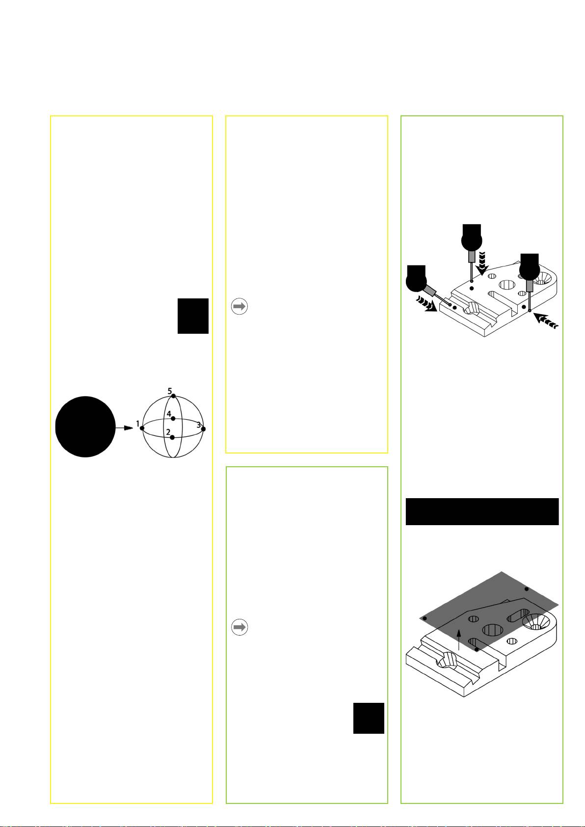
9. Qualify the touch probe
• Touch the PROBE HOLDER
icon to display the probe
Note:
properties screen for the
Many more setup functions are available
selected probe.
beyond the minimum parameters
discussed here. Refer to the ND 1400
• Touch the TEACH button to initiate
User Guide for detailed instructions.
probe qualification.
Leveling and aligning the part
• Probe 4 points around the sphere
Perform level and skew alignments to
circumference, and then 1 at the top.
eliminate measurement errors resulting
from misaligned parts.
1. Align the part on the stage
Align the reference edge of the part to a
measurement axis.
2. Level the part
• Press the FINISH button to conclude
• Touch the MEASURE tab to display
Preparing to measure
the probe qualification.
the 3D measure icons, and then touch
the PLANE icon.
1. Power up the ND 1400
10. Error correction
• Check connections to the ND 1400.
Linear (LEC), segmented linear (SLEC)
• Press the POWER SWITCH to power
and nonlinear (NLEC) error correction
the ND 1400. The DRO screen will be
methods can be used to compensate
displayed after system initialization.
for encoder and machine errors.
• Probe a minimum of 3 points on the
Refer to the ND 1400 User Guide for
desired part reference-plane surface
2. Find machine zero (optional)
instructions.
and then press the FINISH key.
Move the stage to cross reference
marks or find hard stops if your system
was set up to establish machine zero at
startup.
Note:
A repeatable machine zero is required
when SLEC or NLEC error correction
is used. Refer to the User’s Guide for
detailed information.
3. Select a unit of measure
Touch the UNIT OF MEASURE
icon to toggle between inches
• Touch the ALIGN and ZERO buttons
and mm.
on the DRO screen to level the plane
at Z = 0.
3
Operation
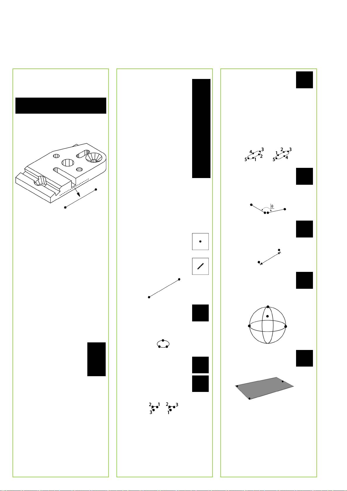
3. Perform a skew alignment
Selecting a projection plane
5. Measure a slot
• Touch the MEASURE tab to display
Projection planes are selected
Touch the SLOT icon and
the 2D measure icons, and then touch
by the user or automatically
probe 5 points in the following
the LINE icon.
by the ND 1400. Touch the
sequence:
PROJECTION button and then
• Two points on a long side
touch a projection plane icon:
• One point in the closest end
• 3D: no projection plane is
• One point in the center of the
selected.
second long side
• Probe a minimum of 2 points on the
• XY, YZ or ZX planes
• Last point on the remaining
reference edge surface of the part
• Auto; ND 1400 selects a
end
and then press the FINISH key.
projection plane based on the
Points can be probed in
probed points.
sequence in either direction.
6. Measure an angle
Touch the ANGLE icon and
probe a minimum of 2 points
on each of the two legs. Press
Measuring features
the FINISH key after each leg.
Features are measured by touching a
feature icon or the MEASURE MAGIC
icon in the 2D or 3D MEASURE tab,
probing points and then pressing the
• Touch the ALIGN button on the DRO
ENTER and FINISH keys.
7. Measure a distance
screen to align the reference edge.
Touch the DISTANCE icon and
1. Measure a point
probe 1 point on each end of
Creating a zero datum
Touch the POINT icon and
the distance.
Probe, construct or create a reference
probe a point.
point and press the ZERO buttons for
each axis on the DRO screen.
2. Measure a line
Touch the LINE icon and probe
a minimum of 2 points.
Presetting a datum
8. Measure a sphere
Probe, construct or create a reference
Touch the SPHERE icon and
point, touch the axis values shown on
probe a minimum of 4 points
the DRO screen and enter preset values
around the surface of the
using the numeric keypad.
sphere in any order.
3. Measure a circle
Saving the reference frame
Touch the CIRCLE icon and
The reference frame for measurements
probe a minimum of 3 points
must be saved once the part is
in any order around the
leveled, aligned and a datum has been
circumference in any order.
established.
• Touch the REFERENCE
FRAME icon and then touch
9. Measure a plane
the SAVE arrow icon. The
4. Measure an arc
Touch the PLANE icon and
reference frame will be
Touch the CIRCLE icon once
probe a minimum of 3 points
saved and given a number.
to display the ARC icon, then
on the surface of the plane.
touch the ARC icon and probe
a minimum of 3 points in
sequence from beginning to
end of the arc.
4
Operation
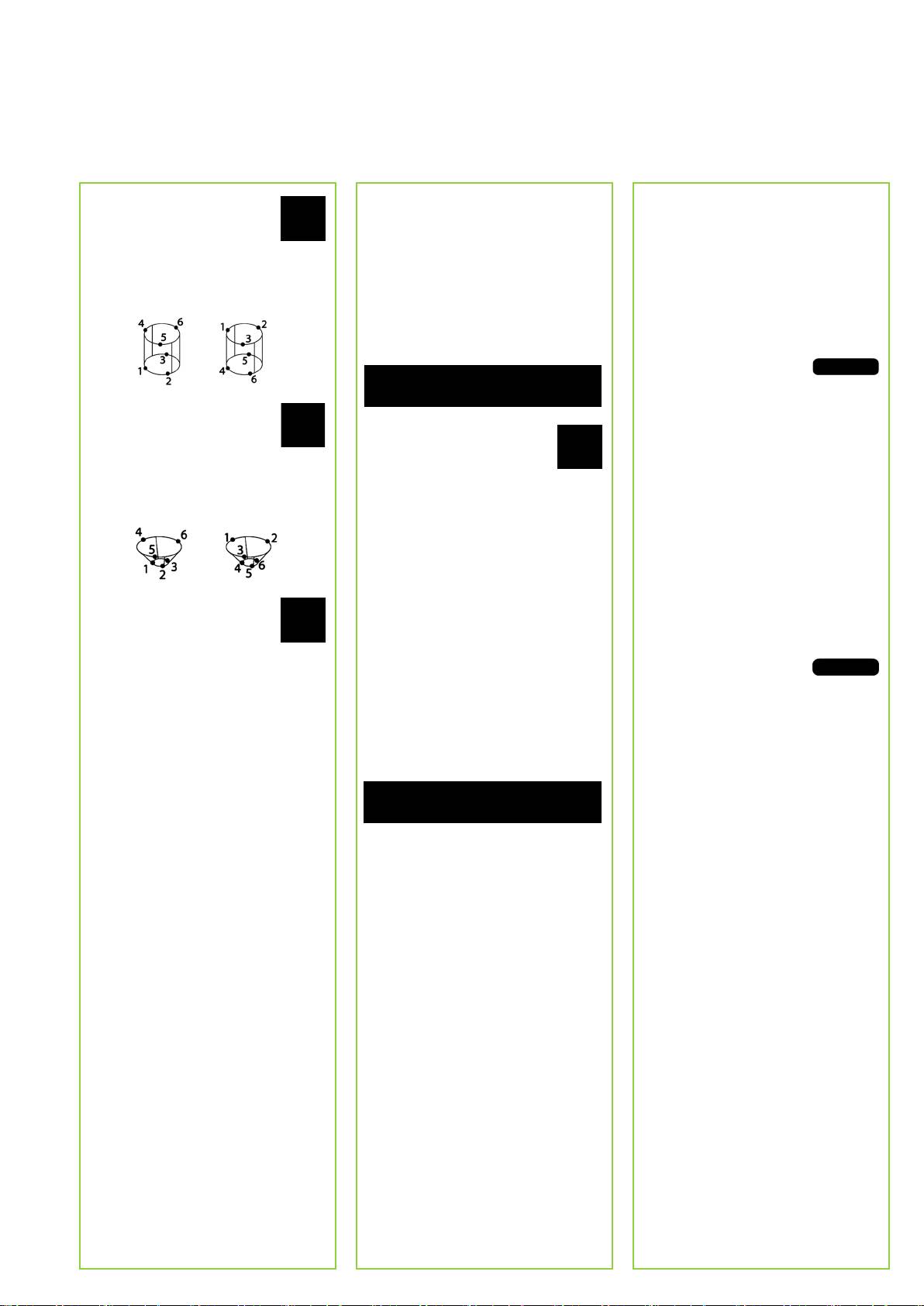
10. Measure a cylinder
Creating Features
Viewing measurement data
Touch the CYLINDER icon and
Features are created by selecting the
Probed data points with form errors
probe 3 points around one end
feature type to be created, entering the
are viewed by selecting a feature in
circumference, 3 points around
required feature data and then pressing
the feature list and touching the VIEW
the other end circumference
the FINISH key.
button.
and then any desired additional
points.
1. Specify the feature type
1. Select a feature
Touch the MEASURE tab and then touch
Touch the desired feature in the feature
a measure icon to specify the type of
list.
feature to be created.
2. Press the VIEW button
Form errors are displayed as
lines extending from data
11. Measure a cone
points to the feature. The
Touch the CONE icon and
2. Enter the feature data
two greatest form errors
probe 3 points around one end
Touch the ENTER DATA icon
are shown in red.
circumference, 3 points around
and then enter data into fields
the other end circumference
shown on the screen.
and then any desired additional
Applying Tolerances
points.
3. Complete the creation
Tolerances are applied by selecting
Press the FINISH key to complete
a feature, touching the TOL button,
the feature creation. The new created
selecting a tolerance type and entering
feature will be shown in the feature list.
tolerance data.
1. Select a feature
12. Use Measure Magic
Constructing Features
Touch the desired feature in the feature
Touch the MEASURE MAGIC
Features are constructed by selecting
list.
icon and probe points on a
the feature type to be constructed,
feature. The feature type will
selecting the parent features and then
2. Press the TOL button
be determined based on the
pressing the FINISH key.
Tolerance types are
pattern and sequence of point
displayed at the bottom
probing.
1. Specify the feature type
of the screen as tolerance
Touch the MEASURE tab and then touch
icons.
a measure icon to specify the type of
feature to be constructed.
3. Select a tolerance
Touch a tolerance icon to select the
desired tolerance type and then touch
the word TOLERANCE at the top left
corner of the screen to select a specific
2. Select the parent features
tolerance.
Touch the desired parent features in the
feature list. Check marks will be shown
4. Enter tolerance data
near the parent features.
Enter NOMINAL and TOLERANCE data
into data fields provided in the tolerance
3. Complete the construction
screen.
Press the FINISH key to complete the
construction. The new constructed
5. View the result
feature will be shown in the feature list.
Green squares near features in the
feature list indicate passed tolerances.
Red squares and outlined characters
on the DRO screen indicate failed
tolerances.
5
Operation
Programming
Saving programs
Reporting Results
Programs are recorded sequences
Programs can be saved to a USB drive.
Reports of results can be sent to a USB
of measurement and other operator
• Plug an empty USB drive into the
printer, USB flash drive or a PC. The
activities stored by the ND 1400 to
USB port on the side of the ND 1400.
report type and destination are specified
be played back later when inspecting
• Touch the PROGRAM tab and touch
in the PRINT setup screen.
identical parts. This guide discusses
the program name.
recording, running, saving, loading and
• Touch the COPY PROGRAM
deleting programs.
icon.
Note:
Refer to the ND 1400 user guide on our
• Press the FINISH key to return to the
web site at: www.heidenhain.de for
Note:
DRO.
details.
Programs can also be copied and edited.
Refer to the User’s Guide for detailed
Loading programs
• Press the SEND key to report
information.
Programs can be loaded from a USB
results.
drive.
1. Record a program
• Plug the USB drive into the USB port
• Touch the PROGRAM tab.
on the side of the ND 1400.
• Touch the C: DRIVE icon
to change drives. The A:
(USB) DRIVE icon and list of
programs stored on the USB
• Touch the round red RECORD icon.
drive will be shown,
• Enter a program name and press the
• Touch the desired program
FINISH key to begin recording.
name in the list and then
• Perform measurement and other
touch the LOAD PROGRAM
steps as usual. Program recording is
icon. The highlighted
indicated by a red program tab.
program will be loaded to the
• To end recording, press the
local (C:) drive.
PROGRAM tab and then press the
• Touch the DRIVE icon. The
square black STOP icon. The new
C: DRIVE will be shown with
program will be stored.
the loaded program in the C:
DRIVE program list.
The loaded program can now be
selected and run.
• Press the FINISH key to end the
programming session and return to
3. Deleting a program
the DRO.
• Touch the PROGRAM tab.
• Touch a program name.
2. Running a program
• Press the CANCEL key. The program
• Touch the PROGRAM tab.
will be deleted.
• Touch a program name.
• Press the black triangular RUN icon.
The feature type and points probed
Note:
will be displayed as points are probed.
Use caution when deleting programs,
• After establishing a reference frame,
and store a backup of the program first.
press the VIEW soft key to see point
Deleted programs cannot be restored.
targeting while points are probed.
• The program will stop automatically
• Press the FINISH key to end the
when all program steps have been
programming session and return to
played. A message box will be
the DRO.
displayed.
• Touch the message box to end the
programming session and return to
the DRO.
6
Table of contents
- ND 1400 QUADRA-CHEK
- ND 1400 QUADRA-CHEK English Setup
- Setup
- Operation
- ND 1400 QUADRA-CHEK Deutsch Setup
- Setup
- Bedienung
- ND 1400 QUADRA-CHEK Français Paramétrage
- Paramétrage
- Fonctionnement
- ND 1400 QUADRA-CHEK Italiano Configurazione
- Configurazione
- Funzionamento
- ND 1400 QUADRA-CHEK Español Ajustes
- Ajustes
- Operación
- ND 1400 QUADRA-CHEK Svenska Inställning
- Inställning
- Handhavande
- ND 1400 QUADRA-CHEK Nederlands Instellen
- Instellen
- Bediening
- ND 1400 QUADRA-CHEK Česky Nastavení
- Nastavení
-
- ND 1400 QUADRA-CHEK Português Configurar
- Configurar
- Funcionamento
- ND 1400 QUADRA-CHEK Język polski Setup
- Setup
-
- ND 1400 QUADRA-CHEK Русский
-
-
- ND 1400 QUADRA-CHEK Türkçe Ayarlar
- Ayar
-
- ND 1400 QUADRA-CHEK Nihongo
-
-
- ND 1400 QUADRA-CHEK
-
-
- ND 1400 QUADRA-CHEK
-
-
- ND 1400 QUADRA-CHEK
