InSinkErator H3300: инструкция
Раздел: Бытовая, кухонная техника, электроника и оборудование
Тип: Кулер для воды
Инструкция к Кулеру для воды InSinkErator H3300
Installation Manual
English
Manual de instalación
Español
Manuel d’installation
Français
Installationshandbuch
Deutsch
Installatiehandleiding
Nederlands
Manual de Instalação
Português
Руководство по установке
Русский
Installationsvejledning
Dansk
Manuale di installazione
Italiano
Instrukcja instalacji
Polski
설치 매뉴얼
한국
2
8
14
20
26
32
38
44
50
56
62
68
F-HC3300C
F-HC3300BR
F-H3300C
F-H3300BR
F-HC1100C
F-HC1100BR
F-GN1100C
F-GN1100BR
SWT-FLTR-1,
-2, -3, -4
SWT-3, -7
steaming
hot water
tap
fi ltered 98°C
water on tap
安装手册
中文
74
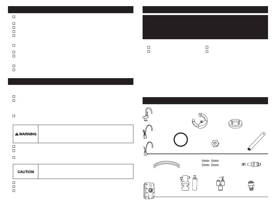
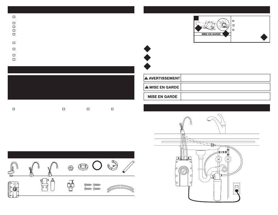
IN THIS PACKAGE
Filter Head & Cartridge
(SWT-FLTR only)
9.5mm White Tubes (2)
HC1100-1, -3
GN1100-1, -3
John Guest Fitting
(Australia only)
19mm Screws (4)
Y-Quick Connector
H3300-1, -3,
HC3300-1, -3
Semicircular
Mounting Plate
Rubber O-Ring
Hex Nut
Hex Tool
Brass Seat
(HC3300, H3300)
SWT-FLTR-1, -3
SWT-3
Back Flow Protection Valve
(Australia/New Zealand only)
Plug (1)
■
For your satisfaction and safety, read all instructions, cautions and warnings before installing or using this
steaming hot water tap.
■
Make sure that all electrical wiring and connections conform to local codes.
■
A standard, earth (grounded) electrical outlet is required under the sink for the tap’s electrical power.
■
The wall outlet powering your tap must have electrical power supplied to it continuously.
■
This outlet must be fused and should not be controlled by the same wall switch that operates the food waste
disposer. Fuse/circuit breaker required is 10 amp for 230 volt (10 amp for 220-240 volt UK) and 15 amp for
120 volt.
■
To ensure proper operation, this unit is not intended to be flushed with chlorine. If you suspect elevated levels
of chlorine in your water, it is recommended to use our water filtration system.
■
In Australia, all plumbing and electrical work must be completed by a qualified tradesperson.
■
To prevent damage or unit not operating properly, the water pressure must be between 172 kPa - 862 kPa
(1.7 bar - 8.6 bar; 25 psi - 125 psi). Ambient (room) temperature between 10ºC and 38ºC. In Australia, an
Australian water mark approved 350 kPa set pressure limiting valve and dual check valve must be used.
■
Moving parts inside the tank causing a rattling noise is normal.
■
If the supply cord is damaged, it must be replaced by the manufacturer, its service agent or similarly qualified
persons in order to avoid a hazard.
WHAT YOU SHOULD KNOW BEFORE YOU BEGIN
ADDITIONAL CONSIDERATIONS
Equipment You May Need:
Equipment Required:
■
Drill
■
Compression fitting, T-fitting
or saddle valve
■
Adjustable spanner
■
Anchors for plasterboard
■
Hole saw
■
Basin nut wrench
■
Hole punch
If you intend to use the sprayer hole in the sink for the hot water tap, you may need a 3.18mm plug or a 6.35mm
cap (
not supplied
) for the sink spray hose line.
See Step 1B.
If you need to cut a mounting hole in the stainless
steel sink, you may need a hole punch or a 35mm - 38mm hole saw made for cutting stainless steel.
What if you don’t have a sprayer hole or don’t want to use it?
Many householders replace the soap dispenser in their sink with a steaming hot water tap. If drilling a hole into a
stainless steel sink or worktop, you can cut a mounting hole for the tap with a hole saw for stainless steel, or you
can use a hole punch.
Hole size requirements: – HC1100, HC3300 and H3300, a 35mm - 38mm hole is required.
– GN1100, hole requirement is 32mm - 38mm.
Consult a professional before drilling into a surface other than stainless steel.
WHAT YOU NEED TO GET STARTED
■
Phillips and flat blade screwdrivers
■
Pencil
■
Tape Measure
■
Spirit level
In Australia and New Zealand, the installation must conform to AS3500.4.1 or AS/NZS 3500.4.2 (Clause 9.b).
Important:
Always arrange the power cord so that it cannot come in contact with hot surfaces.
■
Use this water heater only for its intended use as described in this manual.
■
This appliance is not intended for use by persons (including children) with reduced physical, sensory or mental
capabilities, or lack of experience and knowledge, unless they have been given supervision or instruction
concerning use of appliance by a person responsible for their safety. Children should be supervised to ensure
that they do not play with hot water tap. To reduce the risk of injury, close supervision is required when an
appliance is used near children.
■
Do not operate this product if it has been or appears to be damaged in any manner or after the product
malfunctions, or is dropped. Return the complete product immediately to your retail dealer for inspection, and
if necessary, adjustment or repair.
■
Do not disconnect the product from the power supply by pulling on the cord.
■
Do not use the product for other than its intended use as described in these instructions. The use of accessory
attachments other than those recommended by the manufacturer may cause safety hazards.
■
The recommended connection may be made to an existing cold water line with a branch terminating with a
shutoff valve, a pressure relief and dual check non-return valve sited adjacent to the product.
■
The filter is attached to cold water only.
■
Systems certified for cyst reduction may be used on disinfected water that may contain filterable cysts.
■
The filter is made in the USA.
Electric Shock Hazard:
To reduce the risk of electric shock, do not immerse or expose
the product, flexible cord or plug to rain, moisture or any liquid or when standing in
or on damp or wet surfaces. If any electrical product falls into water, UNPLUG it
immediately. DO NOT REACH INTO THE WATER.
Important:
Prior to reconnecting to
the power supply, the product should be inspected by a qualified technician.
Property Damage:
The flexible vent and outlet tubes must be correctly
connected to the tap supplied by the manufacturer. They must not be obstructed
or connected to a normal type tap or any other type.
Important:
Do not allow the
unit to continuously boil.
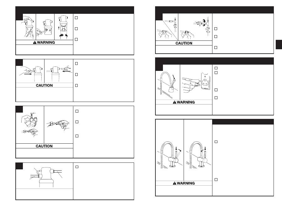
2
Property Damage:
Do not pinch or break copper tubing.
Do not distort the last 25mm of tubing.
HC1100/GN1100
■
Unpack hot water tap components.
■
On a firm, flat surface, carefully
straighten the copper tubing.
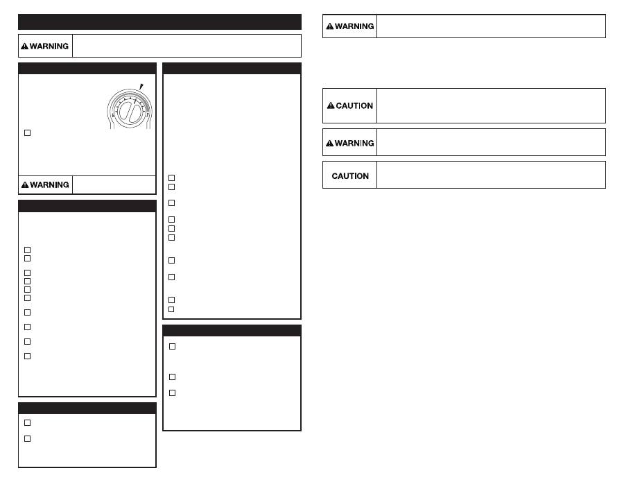
A
These instructions are separated
into main sections, indicated by
numbers, and subsections,
indicated by capital letters. The
manual is set-up this way to
allow you to take a break at any
point after completing a section
or subsection without affecting
the installation process.
Provides a step-by-step narrative describing the installation step, with tick boxes that can be marked as you
progress through the installation.
Contains simple illustrations that provide visual instruction to support the narrative.
CAUTIONS and WARNINGS that will require your attention during the step.
1
2
3
1
2
3
HOW TO USE THIS INSTRUCTION MANUAL
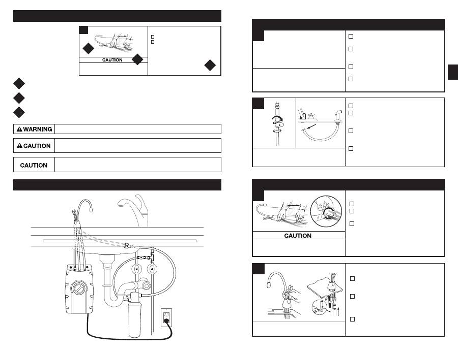
OVERVIEW OF A COMPLETED SET-UP
B
PREPARATION
START HERE
PROPER INSTALLATION SHOULD TAKE ABOUT 2-4 HOURS
■
Identify locations for the tap, tank and
filter (if applicable).
■
Check to make sure there is proper
clearance (see chart at left) for tap
handles to be fully opened.
■
Check to make sure counter is not too
thick (see chart at left).
■
Make sure there is an earth (grounded)
electrical outlet under the sink.
■
Turn off water supply.
■
If using the sink sprayer hose hole,
remove nut that connects sprayer hose
at bottom of tap.
■
Using adjustable spanner, remove nut
connecting sprayer washer flange in
sprayer hole.
■
Close hose opening with either a plug
or a cap
(not supplied).
1
The wall outlet for the tap must have power
supplied to it continuously and must be fused.
It should not be controlled by the same wall
switch that operates the food waste disposer.
If you have to drill through sink or
worktop, you may need to rent or
purchase the appropriate tools.
Required minimum from centre of hole to wall
Maximum counter thickness is 76mm.
A
3
A potentially hazardous situation, which, if not avoided, could result in death or serious injury.
Caution, used with the safety alert symbol, indicates a hazardous situation which, if not
avoided, could result in minor or moderate injury.
Caution, without the safety alert symbol, is used to address practices not related to
personal injury.
Property Damage:
Do not pinch or break copper tubing.
Do not distort the last 25mm of tubing.
HC1100/GN1100
■
Unpack hot water tap components.
■
On a firm, flat surface, carefully
straighten the copper tubing.
■
Ensure that the black O-ring is properly
seated in the base of the tap head (the
groove on the underside of the tap).
A
INSTALLING THE TAP - HC1100/GN1100
2
HC1100/GN1100
■
Feed tubes down through the hole
in the sink or countertop until the base
is at rest.
■
From under the sink, place the
semi-circular mounting plate and hex
nut onto the threaded stud. Ensure tap
head is at desired angle.
■
Insert screwdriver into hole on side of
hex tool (creating a “T”), and use tool
to tighten nut and secure tap.
B
An assistant may be needed to hold
the tap in place while securing.
HC3300 ............. 64mm
H3300 ............... 64mm
HC1100 ............. 67mm
GN1100 ............. 83mm
Property Damage:
Do not pinch or break copper tubing.
Do not distort the last 25mm of tubing.
HC3300/H3300
■
Unpack hot water tap components.
■
The recommended installation for this
tap is the tap handle on the right.
The unique design allows the handle
to be fully functional when placed to
the right or left of the hot water tap.
Determine preferred handle placement
before installing.
A
INSTALLING THE TAP - HC3300/H3300
2
HC3300/H3300
■
Insert rubber O-ring into groove on
brass seat.
■
Place brass seat, O-ring side down,
over hole in sink or worktop.
HC3300/H3300
■
Holding brass seat in place, feed
tubes down through the hole in sink
or worktop until base touches
brass seat.
■
Rotate brass seat until the two retaining
studs fit into the holes on the tap base
and base sits firmly on brass seat.
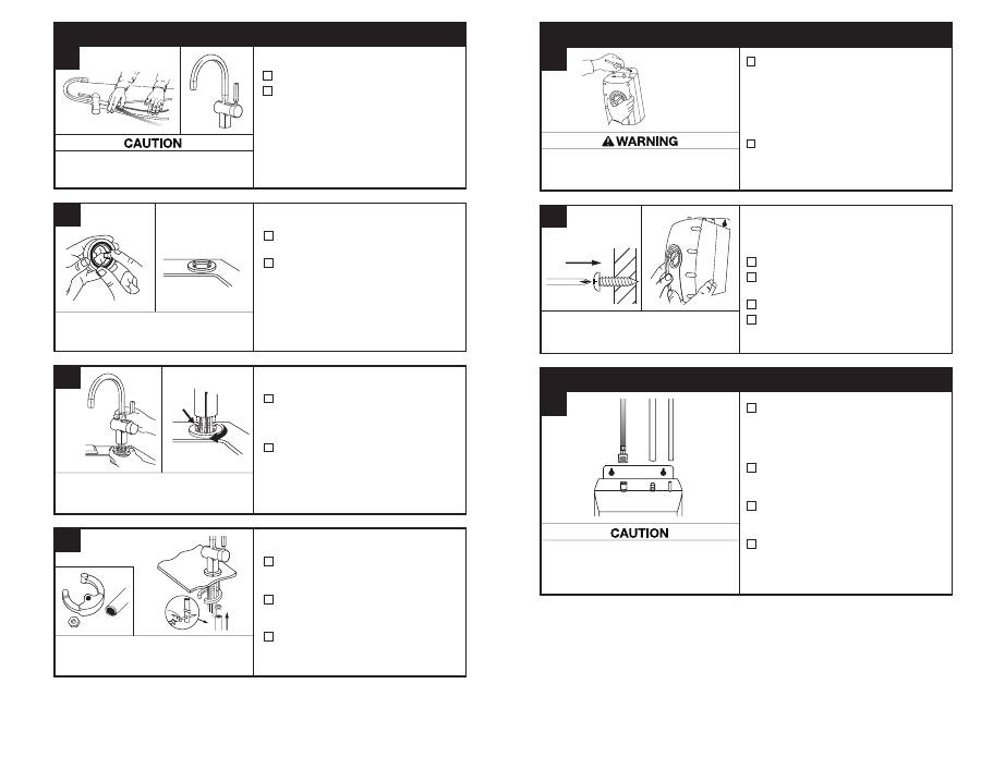
HC3300/H3300
■
From under the sink, place the
semicircular mounting plate onto
the threaded stud.
■
Place hex nut onto the threaded stud.
Ensure tap handle is on preferred side
and that tap head is at desired angle.
■
Insert screwdriver into hole on side of
hex tool (creating a “T”), and use tool
to tighten nut and secure tap.
B
C
D
Wetting O-ring with water prior to
inserting into brass seat helps hold
ring in place during installation.
To ease feeding of tubes through hole, first
insert blue tube with quick-connect attachment
and then insert the remaining tubes.
Semi-circular mounting plate should
encircle all descending tubes and
extend beyond sink hole when tight.
4
Mount tank vertically in an area that allows clearance
on the underside of the tank for drainage, if
necessary. DO NOT over-tighten screws.
■
Pre-drill 3mm pilot holes at marks.
■
Turn screws into pre-drilled holes,
leaving 6.4mm exposed.
■
Hang the tank on the screws.
■
Tighten the screws with only 1/2
turn clockwise.
Screws provided are for use in wood studs or
cabinets only. Use wall anchors (not supplied)
for installation into plasterboard.
CONNECTING TAP TO TANK
MOUNTING THE TANK
■
Select a spot under the sink to mount
tank vertically within reach of both
plumbing and electrical connections.
The tank should be within 400mm or
less of tap water lines and within
760mm or less of a standard earth
(grounded) outlet.
■
While holding tank in place on the spot
selected for installation, use a pencil to
mark locations for 2 hanging screws.
Personal Injury/Property Damage:
Tank must be
located within 400mm of tap and within 760mm or
less of a standard earth (grounded) outlet. DO NOT
extend plumbing or electrical lines.
■
Without depressing the grey button,
place the snap-connect fitting at the
end of the
blue
tube onto the left
plastic fitting on the tank, pushing until
it clicks into place. (1)
■
Slip the flexible
white
tube over
barbed middle fitting and slide down
approximately 12mm. (2)
■
Slip the
small white
tube over the
far right smooth fitting and slide down
approximately 12mm. (3)
■
Visually check for pinched or
crimped tubes.
Hose clamps are not needed for any of the connections.
Tank must be
mounted level
to ensure
proper operation.
Leave 12mm for
hanging tank.
Property Damage:
Pinched or blocked water lines
may cause damage to the water tank. Check to
make sure tubes are connected properly and are
pushed in as mentioned.
3 4
B
A
A
(1)
(2)
(3)
■
Mark hole locations for filter head
and bracket in a spot that allows for
filter replacement.
■
Drill 3mm starter holes and attach
bracket to wall with wood screws,
turning until snug.
■
Remove red filter cap, insert filter
cartridge into filter head and twist
clockwise until “LOCK” arrow on the
filter aligns with arrow on bracket.
Personal Injury:
Do not locate filter above an outlet or other
electrical device. Install head and bracket so that connections
require no stretching, kinking or pinching of tubing.
5
A
■
Determine length of tubing required,
then cut to length making sure the cut
is perpendicular and burr-free.
■
Insert a
white
9.5mm tube into inlet
side of filter head
until it stops. Press
in again to ensure a secure fit.
■
Insert the other
white
tube into outlet
side of filter head
until it stops. Press
in again to ensure a secure fit.
Property Damage:
Tube runs need to form to
the cabinet’s contours to allow storage space with
no sharp bends. Tubes need clean, perpendicular,
burr-free cuts to ensure a true fit.
From water
supply line
To tap
HC1100
From filter or
water supply line
■
HC1100 only:
Remove plug from
“Y” quick connector by holding grey
release ring and gently pulling plug out.
■
Insert the copper tube(s) from the
tap into the 9.5mm to 6.35mm
quick-connector.
Press in again to
ensure a secure fit.
■
Connect the
white
tube from the
right outlet on the filter head into the
quick-connector until it stops.
Press
in again to ensure a secure fit.
Property Damage:
Do not extend the
copper lines farther than the 40cm provided.
■
To redirect filter replacement water
discharge, place 150mm clear tube
over vent hole on the left side of
filter head.
It is normal for approximately 60 ml of
water to discharge when filter is removed.
D
Discharge tube
From water
supply line
To tap
INSTALLING FILTRATION
5
Plug
Plug
B
C
HC3300, H3300,
GN1100
From filter or
water supply line
Scalding Hazard:
The tap dispenses water up to
98ºC, which can instantly cause scalds or burns.
Use care when operating this appliance.
Scalding Hazard:
The tap dispenses water up to
98ºC, which can instantly cause scalds or burns.
Use care when operating this appliance.
■
Turn on the cold water supply.
■
Depress the tap’s
HOT
handle and hold
it until water flows from the spout. Run
the water for at least 3 minutes to flush
lines (both the hot and cold handles on
HC1100 independently).
■
Check all connections to ensure they are
tight and that there are no leaks.
■
Plug in tank and ensure that green light
on front of tank is illuminated.
Note: See box below for special
instructions on operation of HC3300
and H3300 taps.
Featuring two-step hot side activation with
automatic shut off and cool side two-step
activation, which keeps the tap open when
dispensing cool water.
■
HC3300: To dispense instant hot water,
first
press down on the tap handle and
then push the handle backward in the
direction of the red indicator on the top
of the handle. To dispense cool water,
first
press down on the tap handle
and then pull the handle forward in the
direction of the blue indicator on the
handle.
Featuring two-step hot side activation with
automatic shut off.
■
H3300: To dispense instant hot water,
first
press down on the tap handle and
then push the handle backward in the
direction of the red indicator on the top
of the handle.
Water will be cold at first. Allow 12-15 minutes for water to reach target temperature.
Gurgling or hissing is normal during the initial heating cycle.
FILL TANK & THEN CONNECT POWER
7
A
Operating Instructions for HC3300 and H3300 taps
Dispensing Hot Water
(HC3300, H3300)
Dispensing Cool Water
(HC3300)
Property Damage:
Join remaining
tube to cold water supply only.
AUS/NZ: See instructions provided with valve kit
At the other end of the white tube from the filter,
press on the:
■
(UK/IRL) 9.5mm to 15mm quick-connector
and connect to a 15mm water supply.
■
(AUS/NZ) 3/8" to 1/4" bspt John Guest
fitting and connect to a female 1/4" bpst
fitting water supply.
■
Press in again to ensure a secure fit.
FINAL WATER CONNECTION
6
UK/IRL
AUS/NZ
Back flow
protection valve
Wall mount
clip
A
Electric Shock Hazard:
To prevent electrical shock, disconnect power before servicing
unit. Use only a properly earthed (grounded) and polarized electric outlet.
Scalding Hazard:
Do not allow water
to boil. May result in severe burns.
■
Only use mild cleaners to clean the tap
and plastic components.
■
Cleaners with acids, abrasives, alkaline,
and organic solvents will result in
deterioration of the plastic components
and void the warranty.
CLEANING THE TAP AND TANK
Anytime the steaming hot water tap is not used for
extended periods of time, unplug and drain unit. If
it is below freezing you will need to unplug the unit
and drain it.
■
Disconnect power from unit (unplug unit).
■
Push hot water tap lever and allow water
to flow until it is cool.
■
Shut the cold water tap off at the valve.
■
Disconnect tubes from the tank.
■
Unhook tank from wall.
■
Hold tank upside down and drain the
water into the sink.
■
Towel dry any water drippings from
tank area.
■
Reinstall tank to wall and
reconnect tubes.
■
Remove and discard filter cartridge,
if applicable.
■
To put back into working order, install
new filter cartridge (if applicable) and
turn on cold water supply at valve.
Depress the hot water dispenser faucet
lever and hold until water flows from the
spout. Reconnect the electrical cord.
Factory temperature pre-set is
96˚C.
To reset the thermostat
to 96°C, turn the indicator one
notch to the right of vertical.
After adjusting, depress the tap
handle for 20 seconds for water
to re-heat to the new setting.
■
To adjust water temperature, turn
thermostat dial on the front of the tank
clockwise to increase temperature
or turn anticlockwise to decrease
temperature. Repeat if necessary.
All changes should be minimal.
Replace filter cartridge when there is an obvious
decrease in water flow to the tap or if there is an
objectionable taste or odour to the water.
When the inlet and outlet ports have been closed
and the filter’s internal pressure has been relieved,
water (about 60ml) will discharge from vent line.
If the new filter cartridge cannot be inserted,
insert the old one and turn until it stops, remove it
and then retry the new cartridge.
It is recommended that carbon filters be replaced
every 6 months.
FILTER GUIDE AND REPLACEMENT
Filter replacement instructions:
■
Replace with an InSinkErator
®
filter.
■
Place pan or dish towel under the filter to
catch water drainage during change.
■
Slowly turn the cartridge anticlockwise
completely until it stops (1/4 turn).
■
Pull cartridge straight down and discard.
■
Insert new cartridge into filter head.
■
Top surface of cartridge will become
flush with the bottom of the filter head
when fully engaged.
■
Turn the cartridge clockwise until it stops
(1/4 turn).
■
Align the in/out arrow on the head and
bracket assembly to the in/out arrow on
the cartridge.
■
Open tap to expel trapped air.
■
Run water for 3 minutes before usage.
■
Regularly inspect the unit for any signs
of leakage. If there are signs of water
damage, immediately remove the unit
from service.
■
To avoid water damage from leakage,
replace all cut, loose or split tubing
.
■
A drain pan, plumbed to an appropriate
drain or outfitted with a leak detector,
should be used in those applications
where any leakage could cause
property damage.
PROPERTY DAMAGE
SEASONAL STORAGE/DRAINAGE
CARE AND USE
approx. 96°C
ADJUSTING THE THERMOSTAT
6
Property Damage:
To avoid water damage, replace any loose or split tubing. Periodically
inspect the unit for any signs of leakage and immediately remove from service any unit
suspected of leaking.
Personal Injury:
This tank is a non-pressurised tank. DO NOT modify this system. DO
NOT close vent tube or connect other types of taps or valves to the tank. Use only the
InSinkErator tap supplied. Use only parts provided. Contact an authorised InSinkErator
Service agent for repairs or replacement components.
This appliance must be earthed (grounded).
This steaming hot water tap is equipped with a cord that has a
grounding conductor and earth ground pin. The plug must be connected to an appropriate outlet that is properly
installed and earthed (grounded) in accordance with all local codes and ordinances. Do not modify the plug
provided with the appliance – if it will not fit the outlet, have a proper outlet installed by a qualified electrician.
Check with a qualified electrician or tradesman if you are in doubt as to whether the steaming hot water tap is
properly earthed (grounded).
Fire Hazard:
To minimise possibility of fire, DO NOT store flammable items such as rags,
paper or aerosol cans near the tank. DO NOT store or use petrol or other flammable
vapours and liquids in the vicinity of this or any other appliance.
A steaming hot water tap, like any water heater, has a limited life and will eventually fail. To avoid
possible property damage and personal injury, this steaming hot water tap should be regularly
examined for leakage and/or corrosion and replaced when necessary. A drain pan, plumbed to
an appropriate drain or outfitted with a leak detector, should be used in those applications where
any leakage could cause property damage. To check for corrosion, examine the appearance of
the dispensed water in a clear glass once every three (3) months. If there is any discoloration or
rusty appearance, unplug and drain unit as described in the Seasonal Storage/Drainage section
on page 6 of this manual. If the water discoloration remains after draining and refilling unit,
discontinue use and contact an authorized InSinkErator service agent.
Electric Shock Hazard:
Using an ungrounded (no earth ground) or improperly
connected appliance can result in serious injury or death from electrical shock.
Tap:
2-year warranty
SWT-FLTR (tank used with filter):
2-year warranty
SWT (tank used without filter):
1-year warranty
This warranty is provided by InSinkErator, a division of Emerson Electric Co., (
“InSinkErator” or “Manufacturer” or
“we” or “our” or “us”) to the original consumer owner of the InSinkErator product with which this warranty is provided
(the
“InSinkErator Product”), and any subsequent owner of the residence in which the Product was originally installed
(
“Customer” or “you” or “your”).
InSinkErator warrants to Customer that your InSinkErator Product will be free from defects in materials and workmanship,
subject to the exclusions described below, for the
“Warranty Period”, commencing on the later of: (a) the date your
InSinkErator Product is originally installed, (b) the date of purchase, or (c) the date of manufacture as identified by your
InSinkErator Product serial number. You will be required to show written documentation supporting (a) or (b). If you are
unable to provide documentation supporting either (a) or (b), the Warranty Period commencement date will be determined
by Manufacturer, in its sole and absolute discretion, based upon your InSinkErator Product serial number.
What is Covered
This warranty covers defects in materials or workmanship, subject to the exclusions below, in InSinkErator Products used
by a consumer Customer for residential use only, and includes all replacement parts and labor costs. YOUR SOLE AND
EXCLUSIVE REMEDY UNDER THIS LIMITED WARRANTY SHALL BE LIMITED TO REPAIR OR REPLACEMENT OF THE
INSINKERATOR PRODUCT.
What is not Covered
This limited warranty does not extend to and expressly excludes:
• Losses or damages or the inability to operate your InSinkErator Product resulting from conditions beyond the
Manufacturer’s control including, without limitation, accident, alteration, misuse, abuse, neglect, negligence
(other than Manufacturer’s), failure to install, maintain, assemble, or mount the InSinkErator Product in accordance
with Manufacturer’s instructions or local electrical and plumbing codes.
• Wear and tear expected to occur during the normal course of use, including without limitation, cosmetic rust,
scratches, dents or comparable and reasonably expected losses or damages.
In addition to the above exclusions, this warranty does not apply to InSinkErator Products installed in a commercial or
industrial application.
No Other Express Warranty Applies
This warranty is the sole and exclusive warranty provided to the Customer identified above. No other express warranty,
written or verbal, applies. No employee, agent, dealer, or other person is authorized to alter this limited warranty or make
any other warranty on behalf of Manufacturer. The terms of this warranty shall not be modified by the Manufacturer, the
original owner, or their respective successors or assigns.
What we will do to Correct Problems
If your InSinkErator Product does not operate in accordance with the documentation provided to you, or you have questions
concerning your InSinkErator Product or how to determine when service is needed, please see attached Service Agency List.
The following information must be provided as part of your warranty claim: your name, address, phone number, your
InSinkErator Product model and serial number, and if necessary, upon request, written confirmation of either: (a) the date
shown on your installation receipt, or (b) the date shown on your purchase receipt.
Manufacturer or its authorized service representative will determine, in its sole and absolute discretion, if your InSinkErator
Product is covered under this warranty. You will be given the contact information for your closest authorized InSinkErator
Service Center. Please contact your InSinkErator Service Center directly to receive in home warranty repair or replacement
service. Only an authorized InSinkErator service representative may provide warranty service. InSinkErator is not responsible
for warranty claims arising from work performed on your InSinkErator Product by anyone other than an authorized
InSinkErator service representative.
If a covered claim is made during the Warranty Period, Manufacturer will, through its authorized service representative, either
repair or replace your InSinkErator Product. Cost of replacement parts or a new InSinkErator Product, and cost of labor for
repair or installation of the replacement InSinkErator Product are provided at no cost to you. Repair or replacement shall
be determined by Manufacturer or its authorized service representative in their sole discretion. All repair and replacement
services will be provided to you at your home. If Manufacturer determines that your InSinkErator Product must be replaced
rather than repaired, the warranty on the replacement InSinkErator Product will be limited to the unexpired term remaining in
the original Warranty Period.
Limitation of Liability
TO THE EXTENT PERMITTED BY LAW, IN NO EVENT SHALL MANUFACTURER OR ITS AUTHORIZED SERVICE
REPRESENTATIVES BE LIABLE FOR ANY INCIDENTAL, SPECIAL, INDIRECT, OR CONSEQUENTIAL DAMAGES, INCLUDING
ANY ECONOMIC LOSS, WHETHER RESULTING FROM NONPERFORMANCE, USE, MISUSE OR INABILITY TO USE THE
INSINKERATOR PRODUCT OR THE MANUFACTURER’S OR ITS AUTHORIZED SERVICE REPRESENTATIVE’S NEGLIGENCE.
MANUFACTURER SHALL NOT BE LIABLE FOR DAMAGES CAUSED BY DELAY IN PERFORMANCE AND IN NO EVENT,
REGARDLESS OF THE FORM OF THE CLAIM OR CAUSE OF ACTION (WHETHER BASED IN CONTRACT, INFRINGEMENT,
NEGLIGENCE, STRICT LIABILITY, OTHER SORT OR OTHERWISE), SHALL MANUFACTURER’S LIABILITY TO YOU EXCEED
THE PRICE PAID BY THE ORIGINAL OWNER FOR THE INSINKERATOR PRODUCT.
The term "consequential damages" shall include, but not be limited to, loss of anticipated profits, business interruption, loss
of use or revenue, cost of capital or loss or damage to property or equipment.
WARRANTY INFORMATION
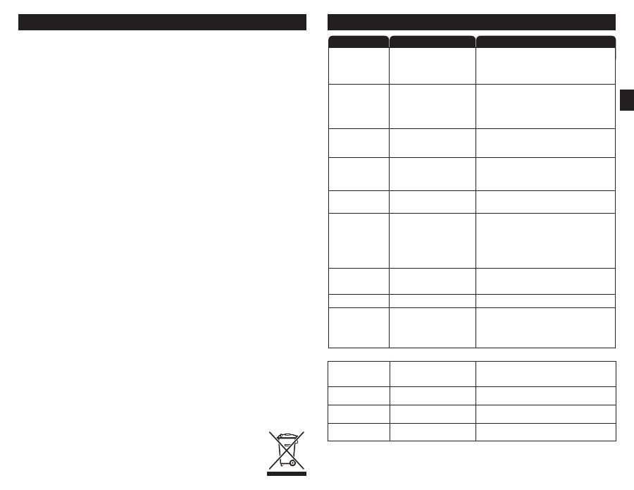
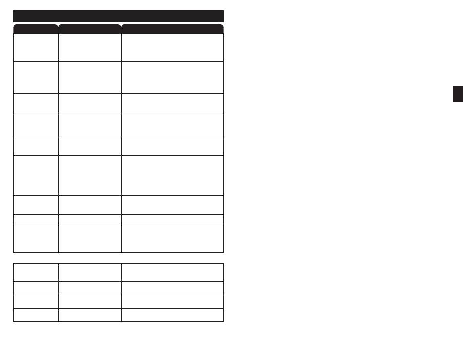
TROUBLESHOOTING
WHAT TO DO
Water and steam
spits forcefully from
spout without turning
on the tap.
• Unit is boiling.
May be normal during initial set-up.
• Depress tap lever to release some water from the tank.
• Adjust water temperature using dial on tank front.
Remember that at higher altitudes, water boils at
lower temperatures.
Water is not hot.
• The unit may not be plugged in.
• The electric outlet is inoperative.
• Make sure the unit is connected to a properly earthed
(grounded) electric outlet.
• Make sure the circuit breaker or fuses are
functioning properly.
• Check that the outlet is not switched off.
Water is too hot
or not hot enough.
• Thermostat is not adjusted to
your needs.
• Adjust the thermostat slowly, then depress or twist tap
handle for 20 seconds to bring in fresh water to be heated
at the new setting. Allow 5-7 minutes for water to reach
new temperature.
Water comes out of vent
instead of spout
• Outlet tube is blocked.
• Check that outlet tube is not kinked, twisted or pinched.
• Unscrew spout end piece and clean out any debris.
Water is dripping
from the spout/vent
intermittently.
• The expansion chamber is not
draining properly due to low
water pressure.
• The spout is blocked.
• Unplug the unit. If the dripping does not stop after a few
minutes, check the supply valve to ensure it is fully open
and there are no obstructions in the water line reducing
the pressure below 172 kPa (1.7 bar; 25 psi).
i.e., a poorly
mounted saddle valve, a clogged water filter, or a partially
opened shut-off valve.
• Unscrew spout end piece and clean out any debris.
Water is dripping
from the spout/vent
constantly.
• Debris in the water line may be
in the tap valve seat causing a
slow water leak.
• Unscrew spout end piece and clean out any debris.
• Depress or twist lever 7-10 times to flush tap & lines.
Divided stream.
• Debris in the end piece.
• Unscrew spout end piece and clean out any debris.
PROBLEM
POSSIBLE CAUSE
LED green light on
front of tank does
not illuminate.
• The unit may not be plugged in.
• The electric outlet is inoperative.
• Make sure that the circuit breaker or fuses are
functioning properly.
• Check that the outlet is not switched off.
Water discoloration/
rusty appearance.
• Corrosion of unit.
• Unplug and drain as described in the Seasonal Storage/
Drainage Section on page 6 of this manual. If the water
discoloration remains after draining and refilling unit,
discontinue use and contact an authorised InSinkErator
service agent.
FILTRATION ISSUES
Water taste or odour.
New filter does not fit.
The filter leaks.
No water flow or low
water flow.
• Filter water flow direction is wrong.
• Filter needs to be flushed out.
• Life of filter has expired.
• Head and bracket not fully rotated.
• Filter O-ring breach.
• Head and bracket not fully rotated.
• Filter O-ring breach.
• Life of filter has expired.
• Review filter tube connection instructions.
• Depress or twist the tap and run until the water is cold.
• If there is no change, replace filter cartridge.
• Take out the new filter, put in old filter.
• Remove, inspect, reinstall filter cartridge.
• Test unit by reinstalling old filter and rotating to full stop.
Check for leaks.
• Replace filter cartridge.
See page 6.
7
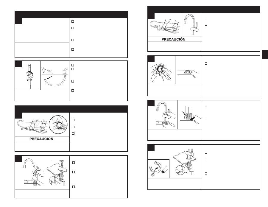
Daños materiales:
No apriete o quiebre la
tubería de cobre. No deforme los últimos
25 mm (1 pulgada) de la tubería.
HC1100/GN1100
■
Desempaquete los componentes del
dispensador de agua caliente.
■
Coloque la tubería de cobre en un lugar
firme y plano, alineándola cuidadosamente.
■
Cerciórese de que la junta tórica negra esté
correctamente asentada en la base de la
cabeza del dispensador (la ranura en la
parte interna del dispensador).
A
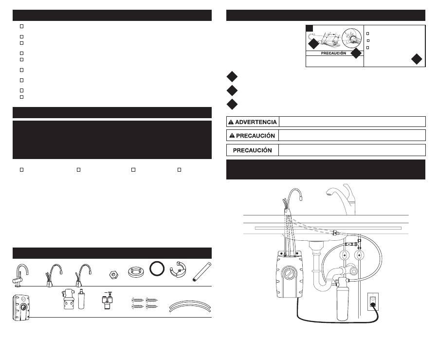
EN ESTE PAQUETE
HC1100-2, -4
GN1100-2, -4
H3300-2, -4
HC3300-2, -4
Placa de montaje
semicircular
Junta
tórica
de goma
Llave
hexagonal
Tuerca
hexagonal
Asiento de bronce
(HC3300, H3300)
Cabeza del filtro
y cartucho
Tubo blanco de 9,5 mm
(0,37 pulgadas) (2)
Tornillos de 19 mm
(0,75 pulgadas) (4)
SWT-FLTR-2, -4
Conector rápido en “Y”
Tapón (1)
■
Para su satisfacción y seguridad, lea todas las instrucciones, cuidados, advertencias y peligros antes de instalar o utilizar
este dispensador de agua caliente.
■
Cerciórese de que todo el cableado y conexiones eléctricas cumplen con los códigos locales.
■
Un tomacorriente estándar con conexión a tierra (con puesta a tierra), es necesario debajo del fregadero para la corriente
eléctrica del dispensador.
■
El tomacorriente de la pared que acciona su dispensador debe tener suministro continuo de energía eléctrica.
■
Este tomacorriente debe tener fusibles y no debe ser controlado por el mismo interruptor de pared que opera el triturador
de desperdicios de comida. El fusible/disyuntor requerido es 10 amperios para 230 voltios y 15 amperios para 120 voltios.
■
Para asegurar una operación apropiada, esta unidad no fue proyectada para enjuagarse con cloro. Si usted sospecha de
elevados niveles de cloro en el agua, le recomendamos que use nuestro sistema de filtración de agua.
■
Para prevenir daños o que la unidad no funcione correctamente, la presión del agua debe estar entre 172 kPa - 862 kPa
(1,7 bar - 8,6 bar; 25 psi - 125 psi). Temperatura ambiental (habitación) entre 10 ºC (50 °F) y 38 ºC (100,4 °F).
■
El movimiento de partes dentro del depósito que causa un ruido que repiquetea es normal.
■
Si el cordón de suministro está dañado, debe ser substituido por el fabricante, agente de servicio o personas calificadas
similares, de modo que se eviten riesgos.
QUÉ DEBE SABER ANTES DE EMPEZAR
Equipo que puede necesitar:
Equipo necesario:
■
Taladro
■
Accesorios de compresión,
Conexión-T o válvula de montaje
■
Llave ajustable
■
Soportes para muro
■
Sierra perforadora
■
Llave de lavabo
■
Perforador
Si usted trata de usar el orificio del vaporizador en el fregadero para el dispensador de agua caliente, puede necesitar un
enchufe de 3,18 mm (0,13 pulgadas) o una tapa de 6,35 mm (0,25 pulgadas) (
no suministrado
) para la línea de manguera
del vaporizador del fregadero.
Vea el Paso 1B.
Si usted necesita cortar un orificio de montaje en el fregadero de acero
inoxidable, puede necesitar un perforador o una sierra perforadora de 35 mm (1,38 pulgadas) a 38 mm (1,5 pulgadas) para
cortar acero inoxidable.
QUÉ NECESITA PARA COMENZAR
■
Destornilladores Phillips y de punta plana
■
Lápiz
■
Cinta métrica
■
Nivel
8
Las instrucciones están divididas en secciones
principales, que se indican con números, y
en subsecciones, que se indican con letras
mayúsculas. El manual está organizado de este
modo para que usted pueda tomar un descanso
en cualquier momento luego de finalizar una
sección o subsección sin que esto afecte al
proceso de instalación.
Proporciona una descripción paso a paso del proceso de instalación, con casillas de verificación que se pueden marcar
conforme a su progreso en la instalación.
Contiene ilustraciones sencillas que proporcionan instrucciones visuales y respaldan la descripción.
Describe las PRECAUCIONES y ADVERTENCIAS a las que deberá prestar atención durante la instalación.
2
3
1
2
3
CÓMO UTILIZAR ESTE MANUAL DE INSTRUCCIONES
¿Qué sucede si no tiene un orificio del pulverizador o no desea utilizarlo?
Muchos propietarios sustituyen el dispensador de jabón de su fregadero por un dispensador de agua caliente. Si perfora
un orificio en un fregadero de acero inoxidable o en la superficie del mesado, puede cortar un orificio de montaje para el
dispensador con una sierra perforadora para acero inoxidable o usando un perforador.
Requisitos del tamaño del orificio: – HC1100, HC3300 y H3300: se requiere un orificio de 35 mm
(1,38 pulgadas) a 38 mm (1,5 pulgadas).
– GN1100: se requiere un orificio de 32 mm (1,26 pulgadas)
a 38 mm (1,5 pulgadas).
Consultar a un profesional antes de perforar en una superficie que no sea de acero inoxidable.
DESCRIPCIÓN GENERAL DE UNA
CONFIGURACIÓN COMPLETA
1
Precaución, empleado junto con el símbolo de alerta, indica una situación riesgosa, la cual,
si no se evita, puede provocar heridas leves o moderadas.
Una situación potencialmente peligrosa que, si no se evita, puede ocasionar lesiones graves
o incluso la muerte.
Precaución, empleado sin el símbolo de alerta, hace referencia a prácticas que no presentan
riesgos de generar lesiones personales.
9
B
PREPARACIÓN
EMPIECE AQUÍ
■
Identifique ubicaciones para el dispensador,
depósito y filtro (si corresponde).
■
Verifique para cerciorarse de que hay espacio
adecuado (vea el gráfico a la izquierda) para
manipular el dispensador para ser abierto
completamente.
■
Verifique para cerciorarse de que el espacio
no esté demasiado lleno (vea el gráfico a
la izquierda).
■
Cerciórese de que haya un tomacorriente
eléctrico con conexión a tierra (con puesta
a tierra) debajo del fregadero.
■
Cierre el suministro de agua.
■
Si usa la manguera vaporizadora en el
orificio del fregadero, retire la tuerca que
conecta el vaporizador en la parte inferior
del dispensador.
■
Usando la llave regulable, retire la tuerca
de conexión de la brida de la arandela del
vaporizador en el orificio del vaporizador.
■
Cierre la abertura de la manguera con un
tapón o una tapa
(no suministrado).
1
El tomacorriente de la pared para el dispensador
debe tener suministro continuo de energía eléctrica
y tener fusible. No debe estar controlado por el
mismo interruptor de pared que opera el triturador
de desperdicios de comida.
Si tiene que taladrar a través del fregadero o
el mesado, es posible que necesite alquilar o
comprar las herramientas apropiadas.
Mínimo requerido del centro del orificio a la pared
El espacio máximo disponible es de 76 mm (2,99 pulgadas).
A
Daños materiales:
No apriete o quiebre la
tubería de cobre. No deforme los últimos
25 mm (1 pulgada) de la tubería.
HC1100/GN1100
■
Desempaquete los componentes del
dispensador de agua caliente.
■
Coloque la tubería de cobre en un lugar
firme y plano, alineándola cuidadosamente.
■
Cerciórese de que la junta tórica negra esté
correctamente asentada en la base de la
cabeza del dispensador (la ranura en la
parte interna del dispensador).
INSTALACIÓN DEL DISPENSADOR - HC1100/GN1100
2
HC1100/GN1100
■
Pase los tubos a través del orificio del
fregadero o del mesado hasta que la base
quede apoyada.
■
Por debajo del fregadero, coloque la placa
de montaje semicircular y la tuerca hexagonal
sobre el perno roscado. Cerciórese de que
la cabeza del dispensador está en el ángulo
deseado.
■
Introduzca el destornillador en el orificio del
lado de la llave hexagonal (formando una “T”)
y use dicha llave para ajustar la tuerca y fijar
el dispensador.
Puede ser necesaria la ayuda de un asistente para sujetar
el dispensador en el lugar mientras lo asegura.
Daños materiales:
No apriete o quiebre la tubería de cobre.
No deforme los últimos 25 mm (1 pulgada) de la tubería.
HC3300/H3300
■
Desempaquete los componentes del
dispensador de agua caliente.
■
Se recomienda instalar el dispensador con
la palanca hacia la derecha.
Su diseño exclusivo permite que la palanca
sea totalmente funcional ya sea que se la
coloque a la derecha o a la izquierda del
dispensador de agua caliente. Determine la
ubicación preferida de la palanca antes de
su instalación.
INSTALACIÓN DEL DISPENSADOR - HC3300/H3300
2
HC3300/H3300
■
Coloque la junta tórica de goma en la ranura
del asiento de bronce.
■
Coloque el asiento de bronce, con la junta
tórica hacia abajo, en el orificio del fregadero
o del mesado.
HC3300/H3300
■
Mientras sostiene el asiento de bronce en su
lugar, pase los tubos a través del orificio del
fregadero o del mesado hasta que la base
toque el asiento de bronce.
■
Gire el asiento de bronce hasta que los dos
pernos de retención se introduzcan en los
orificios de la base del dispensador y ésta
se asiente firmemente sobre el asiento
de bronce.
HC3300/H3300
■
Por debajo del fregadero, coloque la placa de
montaje semicircular sobre el perno roscado.
■
Coloque la tuerca hexagonal sobre el
perno roscado. Cerciórese de que la
palanca del dispensador esté en el lado
preferido y que la cabeza del dispensador
esté en el ángulo deseado.
■
Introduzca el destornillador en el orificio del
lado de la llave hexagonal (formando una “T”)
y use dicha llave para ajustar la tuerca y fijar
el dispensador.
B
C
D
Humedezca la junta tórica con agua antes de insertarla
en el asiento de bronce para ayudar a que la junta se
mantenga en su lugar durante la instalación.
Para que sea fácil introducir los tubos a través del orificio,
primero inserte el tubo azul con el acoplamiento de conexión
rápiday luego introduzca el resto de los tubos.
La placa de montaje semicircular debe rodear todos
los tubos descendentes y debe sobresalir del orificio
del fregadero cuando esté ajustada.
LA INSTALACIÓN CORRECTA DEBE DURAR
APROXIMADAMENTE CERCA DE 2 A 4 HORAS
HC3300 ........ 64 mm (2,5 pulgadas)
H3300 ........... 64 mm (2,5 pulgadas)
HC1100 ......... 67 mm (2,63 pulgadas)
GN1100 ......... 83 mm (3,25 pulgadas)
A
A
B
10
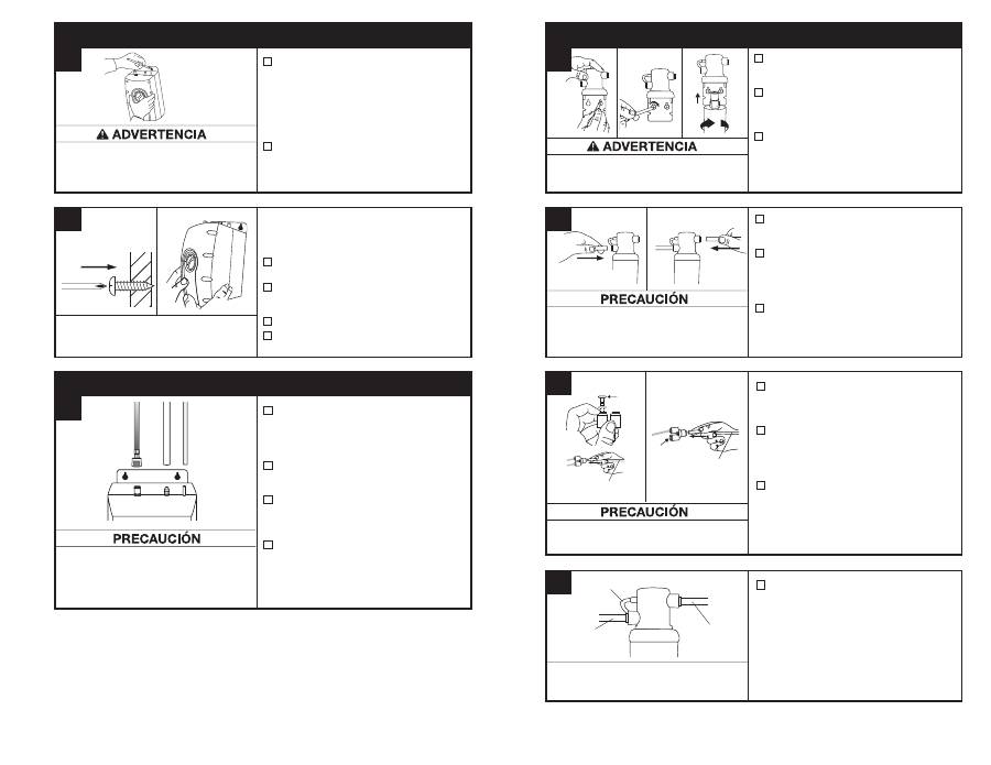
Monte el depósito verticalmente en un área que deje
espacio en la parte inferior del depósito para drenaje,
si es necesario. NO APRIETE demasiado los tornillos.
■
Pre-taladre orificios guía de 3 mm
(0,12 pulgadas) en las marcas.
■
Gire los tornillos en los orificios previamente
taladrados, dejando expuestos 6,4 mm
(0,25 pulgadas).
■
Cuelgue el depósito en los tornillos.
■
Ajuste los tornillos con sólo 1/2 giro en
sentido horario.
Los tornillos proporcionados se deben usar solamente
en travesaños de madera o en gabinetes. Use soportes
de pared (no suministrados) para la instalación en
el muro.
MONTAJE DEL DEPÓSITO
■
Seleccione un punto debajo del fregadero
para montar el depósito verticalmente dentro
del alcance de la tubería y de las conexiones
eléctricas. El depósito debe estar a 400 mm
(15,75 pulgadas) o menos de las líneas de agua
del dispensador y a 760 mm (29,92 pulgadas)
o menos de un tomacorriente estándar con
conexión a tierra (con puesta a tierra).
■
Mientras sostiene el depósito en su lugar en el
punto seleccionado para la instalación, marque
con un lápiz la ubicación para los 2 tornillos
para colgar.
Lesiones personales/Daños materiales:
El depósito se debe
ubicar a 400 mm (15,75 pulgadas) del dispensador y a 760 mm
(29,92 pulgadas) o menos del tomacorriente estándar con
conexión a tierra (con puesta a tierra). NO extienda las tuberías
ni las líneas eléctricas.
■
Sin presionar el botón gris, coloque el
adaptador de encaje a presión en el extremo
del tubo
azul
sobre el ajuste de plástico
izquierdo en el depósito y empuje hasta que
haga clic en el lugar. (1)
■
Deslice el tubo
blanco
flexible sobre el ajuste
intermedio dentado y deslice hacia abajo
aproximadamente 12 mm (0,47 pulgadas). (2)
■
Deslice el
tubo blanco
pequeño sobre el
adaptador liso extremo derecho y deslice
hacia abajo aproximadamente 12 mm
(0,47 pulgadas). (3)
■
Verifique visualmente si los tubos están
comprimidos o con pliegues.
Las abrazaderas de manguera no son necesarias
para ninguna de las conexiones.
El depósito se debe
montar nivelado para
asegurar una operación
correcta.
Deje 12 mm (0,47
pulgadas) para
colgar el depósito.
Daños materiales:
Las líneas de agua comprimidas
o bloqueadas pueden provocar daños en el depósito
de agua. Verifique para cerciorarse de que los tubos
están conectados correctamente y están presionados,
tal como se mencionó.
3
B
A
■
Marque las ubicaciones del orificio para la
cabeza del filtro y el soporte en un punto
que permita el reemplazo del filtro.
■
Perfore orificios con broca de 3 mm
(0,12 pulgadas) y fije el soporte a la pared
con tornillos para madera, girando hasta
ajustarlo.
■
Retire la tapa roja del filtro, introduzca el
cartucho del filtro en la cabeza del filtro y
gire en sentido horario, hasta que la flecha
“CERRAR” del filtro esté alineada con la
flecha del soporte.
Lesiones personales:
No coloque el filtro citado anteriormente
sobre un tomacorriente o dispositivo eléctrico. Instale la cabeza
y el soporte de manera que las conexiones no necesiten estirar,
enroscar ni apretar la tubería.
5
A
■
Determine la longitud de la tubería requerida,
luego corte en la longitud necesaria en forma
perpendicular y libre de rebabas.
■
Introduzca un tubo
blanco
de 9,5 mm
(0,37 pulgadas) del lado de la entrada de
la cabeza del filtro
hasta que se detenga.
Presiónelo nuevamente para cerciorarse
de que está bien ajustado.
■
Introduzca el otro tubo
blanco
en la boca
de salida de la cabeza del filtro hasta que
se detenga.
Presiónelo nuevamente para
cerciorarse de que está bien ajustado.
Daños materiales:
El tubo necesita correr para formar el
contorno del gabinete y permitir espacio de almacenaje sin curvas
agudas. Los tubos necesitan cortes limpios, perpendiculares, libres
de rebabas para asegurar un ajuste adecuado.
De la línea de
suministro de agua
Al dispensador
HC1100
HC3300, H3300,
GN1100
Del filtro o de la línea de
suministro de agua
Del filtro o de la línea de
suministro de agua
■
Solo HC1100:
Retire el tapón del empalme
de conexión rápida en “Y” sosteniendo el
anillo de liberación gris y jalando suavemente
el tapón.
■
Introduzca los tubos de cobre del dispensador
en el conector rápido de 9,5 mm (0,37 pulgadas)
a 6,35 mm (0,25 pulgadas).
Presiónelo
nuevamente para cerciorarse de que está
bien ajustado.
■
Conecte el tubo
blanco
de la boca de
entrada derecha en la cabeza del filtro dentro
del conector rápido hasta que se detenga.
Presiónelo nuevamente para cerciorarse
de que está bien ajustado.
Daños materiales:
No extienda las líneas de cobre más
allá de los 40 cm (15,74 pulgadas) establecidos.
■
Para redireccionar la descarga del agua de
reemplazo del filtro, coloque el tubo claro de
150 mm (5,91 pulgadas) sobre el respiradero
en el lado izquierdo de la cabeza del filtro.
Es normal que se descargue aproximadamente
60 ml (0,01 gal) de agua cuando se retira el filtro.
Tubo de descarga
De la línea de
suministro de agua
Al dispensador
INSTALACIÓN DE LA FILTRACIÓN
Tapón
Tapón
CONEXIÓN DEL DISPENSADOR AL DEPÓSITO
4
A
B
C
D
(1)
(2)
(3)
■
Utilice sólo limpiadores suaves para limpiar
el dispensador y los componentes plásticos.
■
Los limpiadores con ácidos, abrasivos,
solventes alcalinos y orgánicos dañan los
componentes plásticos y anulan la garantía.
LIMPIEZA DEL DISPENSADOR Y DEL DEPÓSITO
Riesgo de descarga eléctrica:
Para prevenir descargas eléctricas, desconecte la
corriente eléctrica antes de reparar la unidad. Utilice solamente un tomacorriente eléctrico
debidamente polarizado y con conexión a tierra (puesta a tierra).
11
Riesgo de escaldado:
No deje
que el agua hierva. Ello podría
ocasionar quemaduras graves.
La temperatura preestablecida de fábrica
es de 96 °C (204,8 °F).
Para reajustar el
termostato a 96 °C (204,8 °F),
gire el indicador un poco a la derecha
del vertical.
Después de ajustar, presione
la perilla del dispensador durante 20
segundos para que el agua se vuelva a
calentar según el nuevo ajuste.
■
Para ajustar la temperatura
del agua, gire el dial del
termostato en el frente del depósito en sentido
horario para incrementar la temperatura o
gire en sentido antihorario para disminuir la
temperatura. Repita si es necesario. Todos los
cambios deben ser mínimos.
Reemplace el cartucho del filtro cuando haya una disminución
evidente en el flujo de agua del dispensador o si hay un sabor
u olor desagradable en el agua.
Una vez que haya cerrado los orificios de entrada y
salida, y que la presión interna del filtro haya disminuido,
el agua (cerca de 60 ml [2 onzas]) fluirá desde la tubería
de ventilación.
Si no se puede colocar el nuevo cartucho del filtro,
introduzca el anterior y gírelo hasta que se asiente, a
continuación, retírelo y vuelva a insertar el cartucho nuevo.
Es recomendable que los filtros de carbón se reemplacen
cada 6 meses.
GUÍA DE FILTRO Y REEMPLAZO
Instrucciones para reemplazo de filtro:
■
Reemplace con un filtro InSinkErator
®
.
■
Coloque una cacerola o un secador de platos
debajo del filtro para contener el drenaje del
agua durante el cambio.
■
Gire lentamente el cartucho en sentido
antihorario completamente hasta que se
detenga (1/4 de giro).
■
Jale del cartucho en línea recta y hacia abajo,
y deséchelo.
■
Introduzca el nuevo cartucho en la cabeza
del filtro.
■
Cuando el cartucho esté completamente
encajado, la superficie superior de éste
quedará a ras de la parte inferior de la cabeza
del filtro.
■
Gire el cartucho en sentido horario hasta que
se detenga (1/4 de giro).
■
Alinee la flecha de entrada/salida de la cabeza
y el ensamblado del soporte con la flecha de
entrada/salida del cartucho.
■
Abra el dispensador para expulsar el
aire contenido.
■
Deje correr el agua durante 3 minutos antes
de usarla.
■
Examine regularmente la unidad por cualquier
señal de fuga. Si hay señales de daño causado
por el agua, retire inmediatamente la unidad
de servicio.
■
Para evitar daños causados por el agua de
la fuga, sustituya toda tubería cortada, floja
o rajada
.
■
Se recomienda instalar un depósito de
desagüe conectado a un desagüe adecuado o
equipado con un detector de fugas en aquellas
aplicaciones en las que las fugas pueden
ocasionar daños materiales.
CUIDADO Y USO
aprox. 96 °C
(204,8 °F)
AJUSTE DEL TERMOSTATO
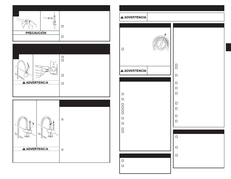
Riesgo de escaldado:
El dispensador suministra
agua hasta 98 ºC (208,4 ºF), lo cual puede provocar
instantáneamente escaldaduras o quemaduras. Tenga
especial cuidado cuando use esta operación.
Riesgo de escaldado:
El dispensador suministra
agua hasta 98 ºC (208,4 ºF), lo cual puede provocar
instantáneamente escaldaduras o quemaduras. Tenga
especial cuidado cuando use esta operación.
Daños materiales:
Acople el tubo restante
sólo al suministro de agua fría.
Debido a que los tamaños de tubería del suministro de
agua son diferentes en cada país, se incluyen hasta
cinco conexiones rápidas de ajuste de agua:
9,5 mm
(3/8") a 12,7 mm (1/2"), 9,5 mm (3/8") a 6,35 mm (1/4")
y 9,5 mm (3/8") a 12,7 mm (1/2") NPT
■
En el otro extremo del tubo blanco del filtro,
presione sobre uno de los ajustes mencionados
anteriormente para resolver sus necesidades y
conectar al suministro de agua.
■
Presiónelo nuevamente para asegurarse
de que está bien ajustado.
■
Abra el suministro de agua fría.
■
Presione la palanca
CALIENTE
del dispensador
y manténgala hasta que el flujo de agua
salga por el surtidor. Deje correr el agua
por lo menos por 3 minutos para enjuagar
las líneas (ambas palancas caliente y fría
independientemente en el HC1100).
■
Inspeccione todas las conexiones para
asegurarse de que estén ajustadas
correctamente y que no haya fugas.
■
Enchufe el depósito y cerciórese de que la luz
verde enfrente del depósito esté encendida.
Nota: Vea el cuadro que sigue para obtener
instrucciones especiales sobre la operación
de los dispensadores HC3300 y H3300.
El agua estará fría al inicio.
Deje de 12 a 15 minutos para que el agua alcance la temperatura deseada.
Es normal que se oigan ruidos sibilantes o de borboteo durante el ciclo de calentamiento inicial.
CONEXIÓN FINAL DEL AGUA
A
Instrucciones de operación para los dispensadores
HC3300 y H3300
Utilización del agua caliente
(HC3300, H3300)
Utilización del agua fría
(HC3300)
LLENADO DEL TANQUE Y CONEXIÓN
DEL SUMINISTRO ELÉCTRICO
A
ALMACENAMIENTO TEMPORAL/DRENAJE
DAÑOS A LA PROPIEDAD
6 7
Cuenta con activación del lado caliente de dos
pasos con cierre automático y activación del lado
frío de dos pasos, lo que mantiene el dispensador
abierto al momento de suministrar agua fría.
■
HC3300: Para utilizar agua caliente
instantánea, primero
presione hacia abajo
la palanca del dispensador y luego empuje
la palanca hacia atrás en el sentido del
indicador rojo que se encuentra en la parte
superior de la palanca. Para utilizar agua fría,
primero
presione hacia abajo la palanca del
dispensador y luego tire de la palanca hacia
adelante en el sentido del indicador azul de la
palanca.
Cuenta con activación del lado caliente de dos
pasos con cierre automático.
■
H3300: Para utilizar agua caliente instantánea,
primero
presione hacia abajo la palanca del
dispensador y luego empuje la palanca hacia
atrás en el sentido del indicador rojo que se
encuentra en la parte superior de la palanca.
Cada vez que el dispensador de agua caliente no se utilice
por periodos prolongados, desenchufe y drene la unidad. Si
la temperatura está por debajo de los cero grados, deberá
desenchufar la unidad y drenarla.
■
Desconecte la energía de la unidad
(desconecte la unidad).
■
Empuje la palanca del dispensador de agua caliente
y deje que el agua fluya hasta que esté fría.
■
Cierre el dispensador de agua fría en la válvula.
■
Desconecte los tubos del depósito.
■
Desenganche el depósito de la pared.
■
Sostenga el depósito volteado hacia abajo y
drene el agua dentro del fregadero.
■
Seque con una toalla los restos de agua del
área del depósito.
■
Reinstale el depósito en la pared y reconecte
los tubos.
■
Retire y deseche el cartucho del filtro, si corresponde.
■
Para colocar nuevamente en perfecto
funcionamiento la unidad, instale el nuevo
cartucho del filtro (si corresponde) y abra el
suministro de agua fría en la válvula. Pulse
la palanca del grifo del dispensador de agua
caliente y manténgala así hasta que el flujo de
agua salga por el surtidor. Reconecte el cable
de alimentación eléctrico.
Riesgo de descarga eléctrica:
Utilizar un aparato conectado incorrectamente o sin
conexión a tierra (ninguna puesta a tierra), puede ocasionar lesiones graves o incluso
la muerte por descarga eléctrica.
Daños materiales:
Para evitar daños causados por el agua, reemplace cualquier
tubería suelta o rajada. Periódicamente, inspeccione la unidad por cualquier señal de
fuga e, inmediatamente, retire de servicio cualquier unidad sospechosa de fuga.
12
Lesiones personales:
Este depósito es un depósito no presurizado. NO modifique
este sistema. NO cierre el tubo de ventilación ni conecte otro tipo de dispensadores
o válvulas al depósito. Use sólo el dispensador InSinkErator suministrado. Use sólo
las piezas suministradas. Comuníquese con un agente de Servicio InSinkErator
autorizado para reparar o reemplazar los componentes.
Este aparato debe tener conexión a tierra (puesto a tierra).
Este dispensador de agua caliente está equipado con un
cordón que tiene un conductor a tierra y una espiga puesta a tierra. El enchufe debe estar conectado a un tomacorriente
apropiado que esté instalado correctamente y con conexión a tierra (puesta a tierra) de acuerdo con todos los reglamentos
y códigos locales. No cambie el enchufe que viene con el aparato. Si no coincide con el tipo de tomacorriente, pídale a
un electricista calificado que instale un tomacorriente adecuado. Consulte con un electricista calificado o especialista
en reparaciones si tiene dudas sobre el dispensador de agua caliente, si es que está con una adecuada conexión a tierra
(puesta a tierra).
Riesgo de incendio:
Para disminuir las posibilidades de que se produzca un incendio,
NO guarde productos inflamables, tales como trapos, papel o aerosol enlatados, cerca
del depósito. NO almacene ni utilice gasolina u otros vapores o líquidos inflamables
cerca de este ni de ningún otro aparato.
Un dispensador de agua caliente, como cualquier calentador de agua, tiene una vida limitada y
eventualmente fallará. Para evitar posibles daños materiales o lesiones personales, este dispensador
de agua caliente debe ser regularmente examinado por fugas y reemplazado cuando sea necesario.
Se recomienda instalar un depósito de desagüe conectado a un desagüe adecuado o equipado con
un detector de fugas en aquellas aplicaciones en las que las fugas pueden ocasionar daños materiales.
Para buscar signos de corrosión, examine el aspecto del agua dispensada en un vaso transparente
una vez cada tres (3) meses. Si se aprecia coloración o apariencia de oxidado, desenchufe y drene
la unidad como se indica en la sección Almacenamiento temporal/drenaje de la página 11 de este
manual. Si persiste la coloración del agua luego del drenaje y el llenado de la unidad, discontinúe
el uso y comuníquese con un agente de servicio autorizado de InSinkErator.
Esta es una garantía que InSinkErator, una división de Emerson Electric Co., (
“InSinkErator”, “Fabricante”, “nosotros”, “nos”
o
“nuestro”) brinda al cliente original propietario del producto InSinkErator (el “Producto InSinkErator”) y a cualquier otro
propietario posterior de la residencia en la que se instaló originalmente el Producto (
“Cliente”, “usted” o “su”).
InSinkErator le garantiza al Cliente que su Producto InSinkErator no tendrá defectos en el material o la mano de obra, sujetos
a las exclusiones descritas a continuación, durante el
“Período de garantía”, que comienza luego de: (a) la fecha en la que
se instaló originalmente su Producto InSinkErator, (b) la fecha de compra o (c) la fecha de fabricación indicada por el número
de serie de su Producto InSinkErator. Deberá presentar la documentación escrita correspondiente para justificar (a) o (b). En
caso de que no pueda presentar la documentación para justificar (a) o (b), la fecha de inicio del Período de Garantía quedará
a consideración del Fabricante, bajo su único y absoluto criterio, basado en el número de serie del Producto InSinkErator.
Qué cubre la garantía
Esta garantía cubre los defectos en el material o la mano de obra, sujetos a las exclusiones descritas a continuación, en
lo que respecta a los Productos InSinkErator a los que el Cliente confiera un uso doméstico únicamente, e incluye todas
las piezas de repuesto y los gastos de reparación. SU ÚNICO Y EXCLUSIVO RECURSO SEGÚN LOS TÉRMINOS DE ESTA
GARANTÍA LIMITADA SERÁ LA REPARACIÓN O EL REEMPLAZO DEL PRODUCTO INSINKERATOR.
Qué no cubre la garantía
Esta garantía limitada no se extiende y excluye expresamente lo siguiente:
•
Pérdidas, daños o incapacidad de operar el Producto InSinkErator, como resultado de circunstancias fuera del control
del Fabricante, sin limitaciones, tales como: accidente, alteración, mal uso, abuso, abandono, negligencia (de otra
persona que no sea el Fabricante), instalación, mantenimiento, ensamblaje o montaje inadecuados del Producto
InSinkErator que no respeten las instrucciones del Fabricante o los códigos eléctricos y/o de plomería locales.
•
Desgaste como resultado del uso normal del producto, lo que incluye sin limitaciones, oxidación de la superficie,
rayones, abolladuras o pérdidas o daños similares y razonables.
Además de las exclusiones antes descritas, esta garantía no se aplica en caso de que los Productos InSinkErator se instalen
para fines industriales o comerciales.
No se aplica ninguna otra garantía expresa
Esta es la única y exclusiva garantía que se le brinda al Cliente descrito anteriormente. No se aplica ninguna otra garantía
expresa, oral o escrita. No se autoriza a ningún empleado, agente, distribuidor u otra persona a alterar esta garantía limitada
o a brindar cualquier otra garantía en nombre del Fabricante. Ninguna persona podrá modificar los términos de esta garantía,
independientemente de si se trata del Fabricante, el propietario original o sus respectivos sucesores o beneficiarios.
Qué haremos para solucionar los problemas
Si su Producto InSinkErator no funciona de acuerdo con la documentación que usted recibió, o si tiene dudas acerca de
su Producto InSinkErator o no sabe cómo determinar cuándo necesita servicio técnico, consulte el Listado de Agencias de
Servicio adjunto.
En el reclamo de garantía debe especificar la siguiente información: su nombre, dirección, número de teléfono, modelo y
número de serie de su Producto InSinkErator y, si es necesario o si se lo solicitan, una confirmación por escrito de: (a) la
fecha que figura en su recibo de instalación, o (b) la fecha que figura en su recibo de compra.
El Fabricante o el representante de servicio autorizado determinarán, bajo su único y absoluto criterio, si esta garantía cubre
su Producto InSinkErator. Se le proporcionará la información de contacto del Centro de Servicio Autorizado de InSinkErator
más cercano. Comuníquese directamente con dicho centro para recibir servicios de reparación o reemplazo cubiertos por
la garantía en su hogar. El representante de servicio autorizado de InSinkErator es el único capaz de brindarle el servicio
de garantía. InSinkErator no se hace responsable por los reclamos de garantía que surjan como consecuencia de trabajos
realizados en su Producto InSinkErator por cualquier otra persona que no sea el representante de servicio autorizado de
InSinkErator.
Si un reclamo cubierto se realiza durante el Período de Garantía, el Fabricante reparará o reemplazará su Producto
InSinkErator por intermedio de su representante de servicio autorizado. Usted no deberá afrontar el costo de las piezas de
repuesto o de un nuevo Producto InSinkErator, ni el costo de mano de obra para la reparación o instalación del Producto
InSinkErator de reemplazo. El Fabricante o su representante de servicio autorizado, bajo su exclusivo criterio, determinarán
si es necesaria la reparación o el reemplazo del producto. Recibirá todos los servicios de reparación o reemplazo en su
hogar. Si el Fabricante determina que se debe reemplazar su Producto InSinkErator en vez de repararlo, la garantía del
Producto InSinkErator de reemplazo se limitará al plazo vigente de la garantía original.
Limitación de responsabilidad
EN LA MEDIDA EN QUE LO PERMITA LA LEY, EL FABRICANTE O SUS REPRESENTANTES DE SERVICIO AUTORIZADOS
NO SERÁN RESPONSABLES POR DAÑOS INCIDENTALES, ESPECIALES, INDIRECTOS O CONSECUENTES, TALES COMO
DAÑOS PATRIMONIALES, YA SEA QUE SEAN CONSECUENCIA DEL INCUMPLIMIENTO, USO, MAL USO O INCAPACIDAD
DE USAR EL PRODUCTO INSINKERATOR, O DE LA NEGLIGENCIA DEL FABRICANTE O SUS REPRESENTANTES DE
SERVICIO AUTORIZADOS. EL FABRICANTE NO SERÁ RESPONSABLE POR LOS DAÑOS CAUSADOS POR EL RETRASO
EN EL RENDIMIENTO Y EN NINGÚN CASO, SIN IMPORTAR EL TIPO DE RECLAMO O LAS MEDIDAS IMPLEMENTADAS
(AUNQUE SE BASEN EN EL CONTRATO, UNA CONTRAVENCIÓN, LA NEGLIGENCIA, LA RESPONSABILIDAD ESTRICTA,
OTRO AGRAVIO, ETC.), SU RESPONSABILIDAD EXCEDERÁ EL PRECIO QUE EL PROPIETARIO ORIGINAL HAYA PAGADO
POR EL PRODUCTO INSINKERATOR.
El término “daños consecuentes” debe incluir, entre otros, la pérdida de ganancias anticipadas, la
interrupción de los negocios, la falta de uso o ingresos, el costo del capital, o la pérdida o daño a la
propiedad o al equipo.
INFORMACIÓN DE GARANTÍA
Dispensador:
2 años de garantía
SWT-FLTR (depósito utilizado con el filtro): 2 años de garantía
SWT (depósito utilizado sin el filtro):
1 año de garantía
SOLUCIÓN DE PROBLEMAS
SOLUCIÓN
El agua y el vapor escupen
enérgicamente del surtidor
sin conectar el dispensador.
• La unidad está en ebullición.
Puede ser normal durante la
configuración inicial.
• Presione la palanca del dispensador para liberar algo de agua
del depósito.
• Ajuste la temperatura del agua usando el dial en el frente
del depósito.
Recuerde que en altitudes elevadas, el agua hierve a bajas temperaturas.
El agua no está caliente.
• Puede ser que la unidad no
esté enchufada.
• El tomacorriente no funciona.
• Cerciórese de que la unidad esté conectada adecuadamente
a un tomacorriente con conexión a tierra (con puesta a tierra).
• Cerciórese de que el disyuntor o los fusibles están
funcionando correctamente.
• Verifique que el tomacorriente no está desconectado.
El agua está muy caliente o
no calienta lo suficiente.
• El termostato no está ajustado a
sus necesidades.
• Ajuste el termostato lentamente, luego presione la palanca del
dispensador por 20 segundos para calentar agua fresca en la nueva
configuración. Deje de 5 a 7 minutos para que el agua alcance la
nueva temperatura.
El agua sale del respiradero
en vez del surtidor.
• El tubo de salida está bloqueado.
• Verifique que el tubo de salida no esté deformado, doblado
ni apretado.
• Desatornille el extremo del surtidor y limpie los residuos.
El agua está goteando
del surtidor/respiradero
intermitentemente.
• La cámara de expansión no está
drenando correctamente debido
a la baja presión de agua.
• El surtidor está bloqueado.
• Desconecte la unidad. Si el goteo no se detiene después de algunos
minutos, verifique en la válvula de suministro para cerciorarse de que
está totalmente abierta y no hay obstrucciones en la línea de agua
que reduzcan la presión debajo de 172 kPa (1,7 bar; 25 psi);
esto es,
una válvula de montaje deficientemente montada, un filtro de agua
obstruido o una válvula de cierre parcialmente abierta.
• Desatornille el extremo del surtidor y limpie los residuos.
El agua está goteando
del surtidor/respiradero
constantemente.
• Los desechos en la línea de agua
pueden estar asentados en la válvula
del dispensador, y provocar así una
fuga lenta de agua.
• Desatornille el extremo del surtidor y limpie los residuos.
• Pulse o gire la palanca del grifo de 7 a 10 veces para limpiar el grifo
y las tuberías.
El chorro de agua no
es uniforme.
• Desechos al extremo de la pieza.
• Desatornille el extremo del surtidor y limpie los residuos.
PROBLEMA
CAUSA POSIBLE
El LED de luz verde al
frente del depósito no
está encendido.
• Puede ser que la unidad no esté
enchufada.
• El tomacorriente no funciona.
• Cerciórese de que el disyuntor o los fusibles están
funcionando correctamente.
• Verifique que el tomacorriente no está desconectado.
Decoloración del agua/
apariencia de oxidado.
• Corrosión de la unidad.
• Desenchufe y drene hasta el momento indicado en la sección
Almacenamiento temporal/drenaje de la página 11 de este manual.
Si persiste la decoloración de agua luego del drenaje y el llenado
de la unidad, discontinúe el uso y comuníquese con un agente de
servicio autorizado de InSinkErator.
PROBLEMAS DE FILTRACIÓN
Gusto u olor del agua.
El nuevo filtro no cabe.
El filtro tiene fuga.
No hay flujo de agua o bajo
flujo de agua.
• La dirección del flujo de agua del filtro
es incorrecta.
• El filtro necesita ser enjuagado.
• La vida útil del filtro caducó.
• La cabeza y el soporte no giran
totalmente.
• Rotura de la junta tórica del filtro.
• La cabeza y el soporte no
giran totalmente.
• Rotura de la junta tórica del filtro.
• La vida útil del filtro caducó.
• Revise las instrucciones de conexión del tubo del filtro.
• Pulse o gire la palanca y deje correr el agua hasta que salga fría.
• Si no hay cambios, reemplace el cartucho del filtro.
• Saque el filtro nuevo y ponga el filtro antiguo.
• Retire, inspeccione, reinstale el cartucho del filtro.
• Vuelva a instalar el filtro anterior y gire hasta que se detenga por
completo. Verifique si hay fugas.
• Reemplace el cartucho del filtro.
Vea la página 11.
13
Dommage matériel :
Ne pincez pas ou ne brisez pas le tube
en cuivre. Ne déformez pas les derniers 25 mm du tube.
HC1100/GN1100
■
Déballez les composants de la fontaine
d’eau chaude.
■
Sur une surface ferme et plane, redressez
le tube en cuivre avec précaution.
■
Assurez-vous que le joint torique noir est
correctement assis dans la base de la tête
de la fontaine (cannelure sur la face inférieure
de la fontaine).
A
DANS CE COLIS
HC1100-2, -4
GN1100-2, -4
H3300-2, -4
HC3300-2, -4
Plaque de montage
semi-circulaire
Joint torique en
caoutchouc
Ecrou
hexagonal
Outil
hexagonal
Siège en laiton
(HC3300, H3300)
Tête de cartouche de filtre
Tubes blancs de 9,5 mm (2)
Vis de 19 mm (4)
SWT-FLTR-2, -4
Raccord rapide Y
Bouchon (1)
■
Pour assurer votre satisfaction et votre sécurité, veuillez lire toutes les instructions, mises en garde et avertissements
avant d’installer ou d’utiliser cette fontaine d’eau très chaude.
■
Assurez-vous que le câblage et les raccordements électriques sont conformes aux codes locaux.
■
Une prise électrique standard mise à la terre est requise sous l’évier pour l’alimentation électrique de la fontaine.
■
La prise murale à laquelle est raccordée votre fontaine doit être alimentée en permanence en énergie électrique.
■
Cette prise doit incorporer un fusible et ne devrait pas être commandée par l’interrupteur mural qui commande la mise en
marche du broyeur de déchets alimentaires. Le fusible/disjoncteur doit être de 10 A pour une tension de 230 volts et de
15 A pour une tension de 120 volts.
■
Pour un fonctionnement adéquat, cette unité ne doit pas être nettoyée au chlore. Si vous pensez que la teneur en chlore
de votre eau est élevée, nous vous recommandons d’utiliser notre système de filtration d’eau.
■
Pour éviter d’endommager l’unité ou de l’utiliser de façon inadéquate, la pression doit se situer entre 172 et 862 kPa
(1,7 bar - 8,6 bars; 25 psi - 125 psi). La température ambiante (de la pièce) doit se situer entre 10 ºC et 38 ºC.
■
Le cliquetis produit par les pièces mobiles à l’intérieur du réservoir est normal.
■
Si le cordon électrique est endommagé, il doit être remplacé par le fabricant, son prestataire de services ou un professionnel
qualifié afin d’éviter tout danger.
CE QUE VOUS DEVRIEZ SAVOIR AVANT DE COMMENCER
Outils dont vous pourriez avoir besoin :
Outils requis :
■
Perceuse
■
Raccord à compression,
raccord en T ou vanne à étrier
■
Clé à molette
■
Pièces d’ancrage pour cloisons sèches
■
Scie cylindrique
■
Clé pour lavabo
■
Emporte-pièce
Si vous avez l’intention d’utiliser le trou de la douchette de votre évier pour la fontaine d’eau chaude, vous aurez probablement
besoin d’un bouchon de 3,18 mm ou d’un capuchon de 6,35 mm (
non fournis
) pour le conduit de la douchette.
Voir Etape 1B.
Si vous devez découper un trou de montage dans un évier en acier inoxydable, vous aurez peut-être besoin d’un emporte-pièce
ou d’une scie cylindrique de 35 mm à 38 mm pour couper l’acier.
CE DONT VOUS AVEZ BESOIN POUR COMMENCER
■
Tournevis Phillips et tournevis à pointe plate
■
Crayon
■
Ruban à mesurer
■
Niveau
Ces instructions sont réparties dans des
paragraphes principaux numérotés et dans
des sous-paragraphes désignés par des
lettres capitales. Ce manuel se présente
ainsi pour vous permettre de faire une
pause après n’importe quel paragraphe ou
sous-paragraphe, sans incidence sur le
processus d’installation.
Chaque étape d’installation est décrite point par point et associée à des cases que vous pouvez cocher à mesure que vous
progressez dans le processus d’installation.
Des figures simples illustrent l’instruction pour appuyer la description.
MISES EN GARDE et AVERTISSEMENTS qui devront retenir votre attention pendant l’étape.
2
3
1
2
3
COMMENT UTILISER CE MANUEL D’INSTRUCTIONS
Vous n’utilisez pas le trou de la douchette ou vous ne souhaitez pas l’utiliser ?
De nombreux propriétaires remplacent le distributeur de savon de leur évier par une fontaine d’eau chaude instantanée. Si vous
devez percer un trou dans un évier en acier inoxydable ou un plan de travail afin de monter la fontaine, vous pouvez découper ce
trou avec une scie cylindrique pour acier inoxydable ou un emporte-pièce.
Exigences en matière de dimensions des trous : – HC1100, HC3300 et H3300 : le trou doit être de 35 à 38 mm.
– GN1100 : le trou doit être de 32 à 38 mm.
Consultez un professionnel avant de percer un trou dans un matériau autre que de l’acier inoxydable.
APERCU D’UNE INSTALLATION TERMINEE
1
14
Situation éventuellement dangereuse qui, si elle n’est pas évitée, peut entraîner des
blessures graves, voire fatales.
« Avertissement » utilisé avec le symbole d’alerte Sécurité ; signale une situation dangereuse
qui, si elle n’est pas évitée, pourrait entraîner des blessures mineures ou modérées.
« Avertissement » utilisé sans le symbole d’alerte Sécurité ; se rapporte à des pratiques
qui ne sont pas liées à des blessures.
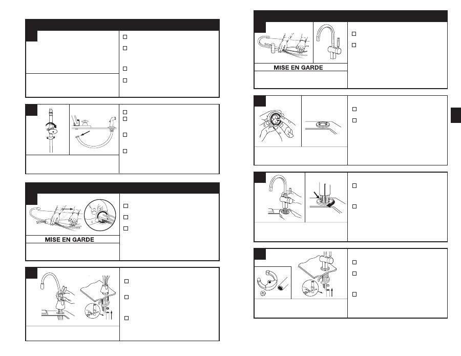
B
PRÉPARATION
COMMENCEZ ICI
■
Déterminez les emplacements de la fontaine,
du réservoir et du filtre (le cas échéant).
■
Assurez-vous de prévoir un dégagement
adéquat (voir tableau à gauche) pour autoriser
l’ouverture complète des manettes de la
fontaine.
■
Vérifiez si le comptoir n’est pas trop épais
(voir tableau à gauche).
■
Assurez-vous qu’il y a une prise de courant
mise à la terre sous l’évier.
■
Coupez l’alimentation d’eau.
■
Si vous utilisez le trou du tuyau de la
douchette, enlevez l’écrou qui raccorde
le tuyau à la base de la fontaine.
■
A l’aide d’une clé à molette, enlevez l’écrou
fixant la bride de la rondelle de la douchette
dans le trou de la douchette.
■
Bouchez l’ouverture du tuyau avec un
bouchon ou un capuchon
(non fourni).
1
La prise murale utilisée pour la fontaine doit être
en permanence alimentée en énergie électrique et
incorporer un fusible. Elle ne doit pas être commandée
par l’interrupteur mural qui commande la mise en
marche du broyeur de déchets alimentaires.
Si vous devez percer l’évier ou le comptoir, vous devrez
peut-être louer ou acheter les outils appropriés.
Minimum requis du centre du trou au mur
L’épaisseur maximum du plan de travail est de 76 mm.
A
Dommage matériel :
Ne pincez pas ou ne brisez pas le tube
en cuivre. Ne déformez pas les derniers 25 mm du tube.
HC1100/GN1100
■
Déballez les composants de la fontaine
d’eau chaude.
■
Sur une surface ferme et plane, redressez
le tube en cuivre avec précaution.
■
Assurez-vous que le joint torique noir est
correctement assis dans la base de la tête
de la fontaine (cannelure sur la face inférieure
de la fontaine).
A
INSTALLATION DE LA FONTAINE - HC1100/GN1100
2
HC1100/GN1100
■
Faites passer les tubes par le trou de l’évier
ou du plan de travail jusqu’à ce que la base
soit bien assise.
■
De sous l’évier, placez le support de montage
semi-circulaire et l’écrou hexagonal sur le
goujon fileté. Assurez-vous que la tête de la
fontaine est à l’angle souhaité.
■
Insérez le tournevis dans le trou situé sur le
côté de l’outil hexagonal (en formant un « T »),
et servez-vous de cet outil pour serrer l’écrou
et fixer la fontaine.
B
Vous aurez peut-être besoin qu’une personne vous aide à
maintenir la fontaine en place pendant que vous la fixez.
Dommage matériel :
Ne pincez pas ou ne brisez pas le tube
en cuivre. Ne déformez pas les derniers 25 mm du tube.
HC3300/H3300
■
Déballez les composants de la fontaine
d’eau chaude.
■
Pour cette fontaine, il est recommandé
d’installer la manette à droite.
Toutefois, la conception unique de cette
fontaine permet à la manette d’être
totalement fonctionnelle qu’elle soit placée
à droite ou à gauche. Vous devez déterminer
l’emplacement de la manette que vous
préférez avant l’installation.
A
INSTALLATION DE LA FONTAINE - HC3300/H3300
2
HC3300/H3300
■
Insérez le joint torique en caoutchouc dans
la cannelure du siège en laiton.
■
Placez le siège en laiton, côté joint torique
dirigé vers le bas, sur le trou de l’évier ou
du plan de travail.
HC3300/H3300
■
Tout en maintenant le siège en laiton en
place, faites passer les tubes par le trou
de l’évier ou du plan de travail jusqu’à ce
que la base contacte le siège en laiton.
■
Faites tourner le siège en laiton jusqu’à ce
que les deux goujons de retenue s’engagent
dans les trous de la base de la fontaine et
que la base soit bien assise sur le siège
en laiton.
HC3300/H3300
■
De sous l’évier, placez le support de montage
semi-circulaire sur le goujon fileté.
■
Placez l’écrou hexagonal sur le goujon fileté.
Assurez-vous que la manette de la fontaine
est du côté que vous souhaitez et que la tête
de la fontaine est à l’angle voulu.
■
Insérez le tournevis dans le trou situé sur le
côté de l’outil hexagonal (en formant un « T »),
et servez-vous de cet outil pour serrer l’écrou
et fixer la fontaine.
B
C
D
Le fait de mouiller le joint torique avant de
l’insérer dans le siège en laiton le maintiendra
en place pendant l’installation.
Pour faciliter le passage des tubes dans le trou,
insérez d’abord le tube bleu à raccord rapide,
puis insérez les tubes restants.
La plaque de montage semi-circulaire devrait
encercler tous les tubes descendants et se prolonger
au-delà du trou de l’évier après avoir été fixée.
UNE INSTALLATION ADEQUATE DEVRAIT
PRENDRE 2 A 4 HEURES ENVIRON.
15
HC3300 ................. 64mm
H3300 .................... 64mm
HC1100 .................. 67mm
GN1100 .................. 83mm
