Ridgid micro IR-100: instruction
Class: Tools, power tools and power equipment
Type:
Manual for Ridgid micro IR-100
micro
IR-100
EN
p. 1
FR
p. 15
ES
p. 29
DE
p. 43
NL
p. 57
IT
p. 71
PT
p. 85
SV
p. 99
DA
p. 113
NO
p. 127
FI
p. 141
PL
p. 155
CZ
p. 169
SK
p. 183
RO
p. 197
HU
p. 211
EL
p. 225
HR
p. 239
SL
p. 253
SR
p. 267
RU
p. 281
TR
p. 295
RIDGE TOOL COMPANY

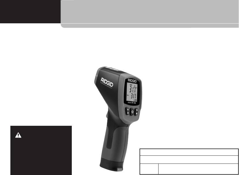
micro IR-100
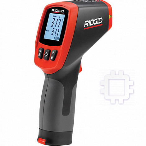
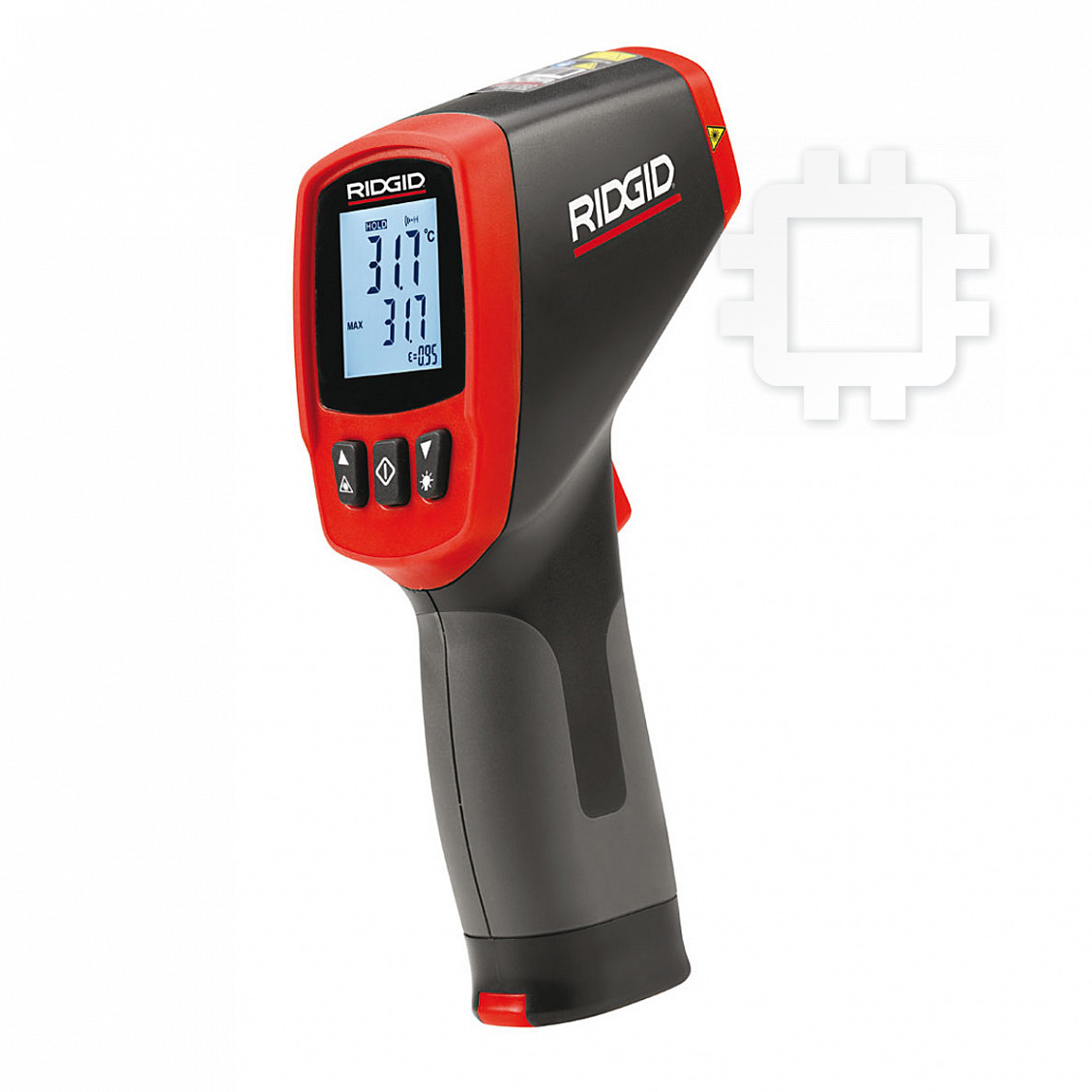
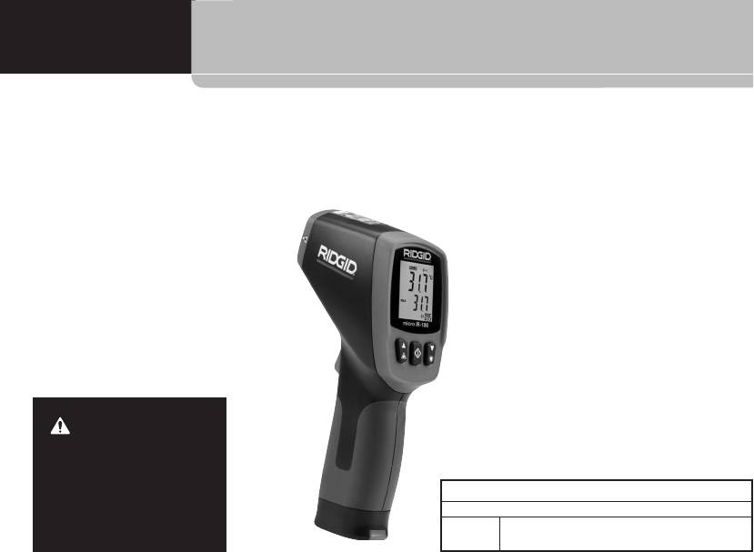
micro IR-100
Non-Contact Infrared Thermometer
WARNING
Read this operator’s manual
carefully before using this tool.
Failure to understand and fol-
low the contents of this manual
micro IR-100 Non-Contact Infrared Thermometer
may result in electrical shock,
Record Serial Number below and retain product serial number which is located on nameplate.
fire and/or serious personal in-
Serial
jury.
No.

micro IR-100 Non-Contact Infrared Thermometer
Table of Contents
Recording Form for Machine Serial Number .........................1
Menu Button Use..................................................................12
Safety Symbols.........................................................................3
High Alarm ............................................................................12
Low Alarm.............................................................................12
General Safety Rules
Temperature Display Units-C/F ............................................12
Work Area Safety ...................................................................4
Electrical Safety......................................................................4
Cleaning ..................................................................................12
Personal Safety ......................................................................4
Storage....................................................................................12
Equipment Use and Care .......................................................4
Service and Repair .................................................................13
Service....................................................................................5
Disposal ..................................................................................13
Specific Safety Information
Infrared Thermometer Safety .................................................5
Battery Disposal.....................................................................13
Description, Specifications and Standard Equipment
Lifetime Warranty ....................................................Back Cover
Description..............................................................................5
*Original Instructions
Specifications .........................................................................6
Parts .......................................................................................7
LCD Display Icons ..................................................................7
Standard Equipment...............................................................7
Laser Classification .................................................................8
FCC Statement..........................................................................8
Electromagnetic Compatibility (EMC) ....................................8
Changing/Installing Batteries..................................................8
Pre-Operation Inspection ........................................................9
Set-Up and Operation
Set-Up ..................................................................................10
Operation
Turning ON and OFF (Taking Measurements)......................11
micro IR-100 Controls
Continuous Measurement (Scanning) Mode ........................11
Laser Enabled/Disabled........................................................11
Backlight ...............................................................................12
2
Ridge Tool Company

micro IR-100 Non-Contact Infrared Thermometer
Safety Symbols
In this operatorʼs manual and on the product, safety symbols and signal words are used to communicate important safety information. This
section is provided to improve understanding of these signal words and symbols.
This is the safety alert symbol. It is used to alert you to potential personal injury hazards. Obey all safety messages that follow this
symbol to avoid possible injury or death.
DANGER
DANGER indicates a hazardous situation which, if not avoided, will result in death or serious injury.
WARNING
WARNING indicates a hazardous situation which, if not avoided, could result in death or serious injury.
CAUTION
CAUTION indicates a hazardous situation which, if not avoided, could result in minor or moderate injury.
NOTICE
NOTICE indicates information that relates to the protection of property.
This symbol means read the operatorʼs manual carefully before using the equipment. The operatorʼs manual contains important
information on the safe and proper operation of the equipment.
This symbol means this device contains a Class 2 Laser.
This symbol means do not stare into the laser beam.
This symbol warns of the presence and hazard of a laser beam.
Ridge Tool Company
3
CAUTION
LASER RADIATION
DO NOT STARE INTO BEAM
MAXIMUM OUTPUT < 1mW
WAVELENGTH 630-670nm
CLASS 2 LASER PRODUCT
EN 60825-1:1994/A11:1996/A2:2001/A1:2002

micro IR-100 Non-Contact Infrared Thermometer
General Safety Rules
• Use personal protective equipment. Always wear eye protec-
tion. Protective equipment such as dust mask, non-skid safety
WARNING
shoes, hard hat, or hearing protection used for appropriate con-
Read all safety warnings and instructions. Failure to follow the
ditions will reduce personal injuries.
warnings and instructions may result in electric shock, fire
• Do not overreach. Keep proper footing and balance at all
and/or serious injury.
times. This enables better control of the power tool in unex-
SAVE THESE INSTRUCTIONS!
pected situations.
The CE declaration of conformity (890-011-320) will accompany
Equipment Use and Care
this manual as a separate booklet when required.
• Do not force equipment. Use the correct equipment for your
application. The correct equipment will do the job better and
Work Area Safety
safer at the rate for which it is designed.
• Keep your work area clean and well lit. Cluttered or dark areas
• Do not use equipment if the switch does not turn it ON and
invite accidents.
OFF. Any tool that cannot be controlled with the switch is danger-
• Do not operate equipment in explosive atmospheres, such
ous and must be repaired.
as in the presence of flammable liquids, gases or dust. E-
• Disconnect the batteries from the equipment before making
quipment can create sparks which may ignite the dust or fumes.
any adjustments, changing accessories, or storing. Such
• Keep children and by-standers away while operating equip-
preventive safety measures reduce the risk of injury.
ment. Distractions can cause you to lose control.
• Store idle equipment out of the reach of children and do not
allow persons unfamiliar with the equipment or these in-
Electrical Safety
structions to operate the equipment. Equipment can be dan-
•
Avoid body contact with earthed or grounded surfaces such as
gerous in the hands of untrained users.
pipes, radiators, ranges and refrigerators. There is an increased
• Maintain equipment. Check for misalignment or binding of mov-
risk of electrical shock if your body is earthed or grounded.
ing parts, missing parts, breakage of parts and any other condi-
• Do not expose equipment to rain or wet conditions. Water
tion that may affect the equipmentʼs operation. If damaged, have
entering equipment will increase the risk of electrical shock.
the equipment repaired before use. Many accidents are caused
by poorly maintained equipment.
Personal Safety
• Use the equipment and accessories in accordance with
• Stay alert, watch what you are doing and use common
these instructions, taking into account the working condi-
sense when operating equipment. Do not use equipment
tions and the work to be performed. Use of the equipment for
while you are tired or under the influence of drugs, alcohol
operations different from those intended could result in a haz-
or medication. A moment of inattention while operating equip-
ardous situation.
ment may result in serious personal injury.
4
Ridge Tool Company
micro IR-100 Non-Contact Infrared Thermometer
• Use only accessories that are recommended by the manu-
entanglement, burns and other serious injury. Protective equip-
facturer for your equipment. Accessories that may be suitable
ment may be required.
for one piece of equipment may become hazardous when used
If you have any question concerning this RIDGID product:
with other equipment.
• Contact your local RIDGID distributor.
• Keep handles dry and clean; free from oil and grease. Allows
• Visit www.RIDGID.com or www.RIDGID.eu to find your local
for better control of the equipment.
RIDGID contact point.
Service
• Contact RIDGID Technical Services Department at rtctechser-
• Have your equipment serviced by a qualified repair person
vices@emerson.com, or in the U.S. and Canada call (800) 519-
using only identical replacement parts. This will ensure that
3456.
the safety of the tool is maintained.
Description, Specifications
Specific Safety Information
And Standard Equipment
Description
WARNING
This section contains important safety information that is
The RIDGID
®
micro IR-100 Non-Contact Infrared Thermometer pro-
specific to this tool.
vides simple, quick, and accurate surface temperature readings at
Read these precautions carefully before using the RIDGID
®
the push of a button. You simply squeeze the trigger and point the
micro IR-100 Non-Contact Infrared Thermometer to reduce the
ultra-sharp dual class II lasers at the surface being measured. The
risk of eye injury or other serious personal injury.
micro IR-100 provides an immediate temperature measurement on
a clear, easy-to-read backlit LCD display. In addition to numerous
SAVE THESE INSTRUCTIONS!
other uses, this rugged, compact instrument enables professional
Keep this manual with the tool for use by the operator.
tradesman to diagnose heating and ventilation problems, perform
preventative monitoring of electrical motors and systems, trou-
Infrared Thermometer Safety
bleshoot steam traps and quickly check fuses or circuit breakers for
• Do not look into the laser beam. Looking into the laser beam
overheating without contact.
may be hazardous to the eyes. Do not look at the laser beam with
The micro IR-100 uses optics to sense emitted, reflected and trans-
optical aids (such as binoculars or telescopes).
mitted energy, which is collected and focused onto a detector. The
• Do not direct the laser beam towards other people. Make
unitʼs electronics translate the information into a temperature read-
sure the laser is aimed above or below eye level. Laser beams
ing, which is displayed. Lasers are used to assist in aiming.
may be hazardous to the eyes.
• Take appropriate precautions when working near electrical,
moving or hot parts. Close contact may cause electrical shock,
Ridge Tool Company
5
micro IR-100 Non-Contact Infrared Thermometer
Weight...........................................0.6 lbs (0.3 kg)
Specifications
Features
Temperature Range ......................-58°F to 1472°F
• Rapid Detection Function
• Backlight LCD Display
(-50°C to 800°C)
• Dual Class II Laser Sighting
• Trigger Lock
Distance To Spot Ratio .................20 to 1
• Automatic Data Hold
• Set High and Low Alarms
Measuring Accuracy .....................-58°F ~68°F (50°C ~20°C) :
• MAX Temperature Displays
±4.5°F (2.5°C)
• Precise Non-Contact Measurements
68°F ~1472°F (20°C ~800°C)
• Automatic Selection Range and Display Resolution 0.1°F (0.1°C)
±1.0% or ±1.8°F (1.0°C)
Repeatability...................................-58°F ~68°F (50°C ~20°C) :
±2.3°F (1.3°C)
68°F ~1472°F (20°C ~800°C)
±0.5% or ±0.9°F (0.5°C)
Response Time ..............................150ms
Spectral Response.........................8~14um
Emissivity .......................................Fixed, 0.95
Over Range Indication ...................LCD will show “----”
Diode Laser ..................................Output <1mW, Wavelength
630~670nm, Class 2 Laser
Product
Temperature Display.....................Current Temperature, MAX
Temperature
Measuring Units............................Fahrenheit, Celsius
Operating Temperature.................32°F to 122°F (0°C to 50°C)
Storage Temperature ....................14°F to 140°F (-10°C to 60°C)
Display Resolution ..........................0.1°F (0.1°C)
Relative Humidity..........................10%~90% RH Operating,
<80% RH Storage
Batteries ....................................... 9V Battery (1), NEDA 1604A
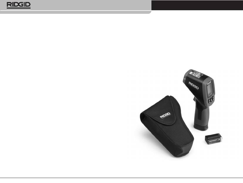
Figure 1 – micro IR-100 Non-Contact Infrared Thermometer
or IEC 6LR61, or Equivalent
IP Rating .......................................IP54
6
Ridge Tool Company
micro IR-100 Non-Contact Infrared Thermometer
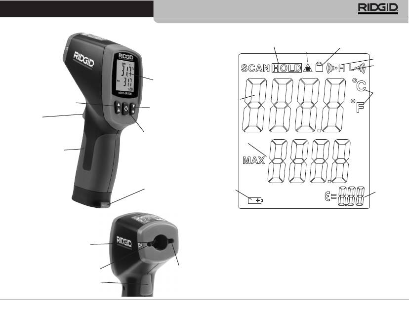
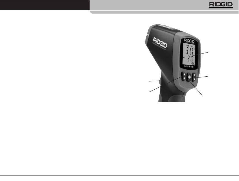
Parts
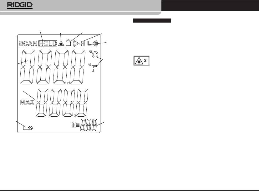
LCD Display Icons
Data Hold
Laser Enable
Lock
High Alarm
Low Alarm
LCD Display
Celsius/-
Current
Fahrenheit
Up Button/Laser Enable
Temperature
Temperature
Down Button/-
Value
Units
Backlight
Trigger
Menu Button
Maximum
Temperature
Handle Grip
Value
Battery
Compartment
Low
Battery
Emissivity
Value
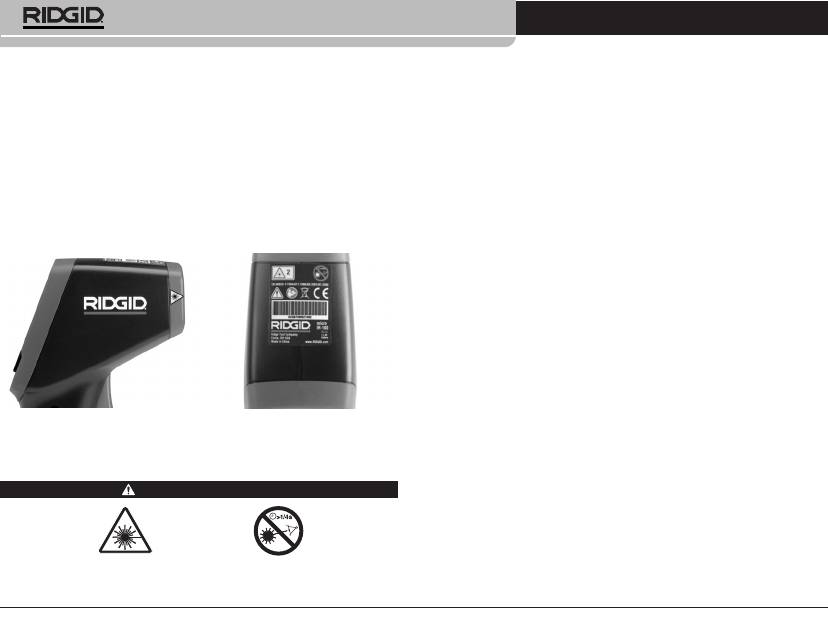
Figure 2 – micro IR-100 Parts
Figure 3 – micro IR-100 Display Icons
Infrared Sensor
Standard Equipment
• micro IR-100
• Battery 1 x 9V
• Carrying Case
• Operator's Manual
Laser
Laser
Trigger
Ridge Tool Company
7
micro IR-100 Non-Contact Infrared Thermometer
NOTICE
This equipment is used to make temperature measure-
Electromagnetic Compatibility (EMC)
ments. Incorrect use or improper application may result in incorrect
The term electromagnetic compatibility is taken to mean the capa-
or inaccurate measurements. Selection of appropriate measure-
bility of the product to function smoothly in an environment where
ment methods for the conditions is the responsibility of the user.
electromagnetic radiation and electrostatic discharges are present
and without causing electromagnet interference to other equipment.
Laser Classification
NOTICE
The RIDGID micro IR-100 conforms to all applicable
The RIDGID micro IR-100 generates a visible laser beam
EMC standards. However, the possibility of it causing interference
that is emitted from the front of the device.
in other devices cannot be precluded.
The device complies with class 2 lasers according to: EN 60825-
1:1994/A11:1996/A2:2001/A1:2002
FCC Statement
This equipment has been tested and found to comply with the lim-
its for a Class B digital device, pursuant to part 15 of the FCC Rules.
These limits are designed to provide reasonable protection against
harmful interference in a residential installation.
This equipment generates, uses, and can radiate radio frequency
energy and, if not installed and used in accordance with the instruc-
tions, may cause harmful interference to radio communications.
However, there is no guarantee that interference will not occur in a
particular installation.
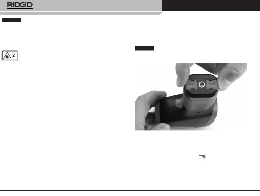
Figure 4 – Removing Battery Compartment
If this equipment does cause harmful interference to radio or tele-
vision reception, which can be determined by turning the equip-
Changing/Installing Batteries
ment off and on, the user is encouraged to try to correct the
interference by one or more of the following measures:
The micro IR-100 is supplied without a battery installed. If the bat-
tery indicator (Figure 3) displays , the battery needs to be re-
• Reorient or relocate the receiving antenna.
placed. Remove the battery prior to long term storage to avoid
• Increase the separation between the equipment and receiver.
battery leakage.
• Consult the dealer or an experienced radio/TV technician for
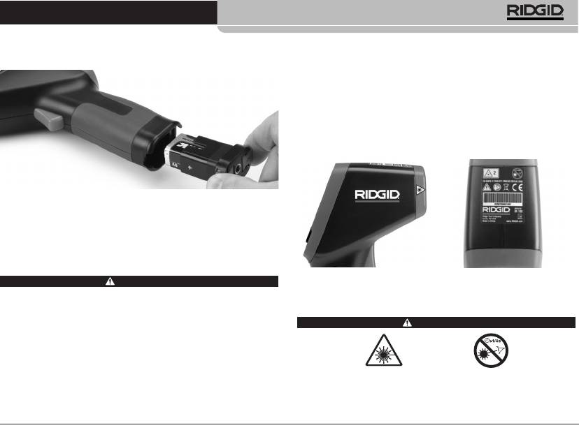
1. Squeeze the battery clips and remove battery compartment
help.
from the thermometer (See Figure 4). If needed, remove bat-
tery.
8
Ridge Tool Company
micro IR-100 Non-Contact Infrared Thermometer
2. Install 9V alkaline battery (6LR61), observing the correct po-
3. Check that the warning labels are present, firmly attached and
larity as indicated on the battery compartment.
readable. (See Figure 6.)
4. If any issues are found during the inspection, do not use the in-
frared thermometer until it has been properly serviced.
5. Following the Operation Instructions, turn the infrared ther-
mometer ON, make a measurement and confirm the same
measurement with another instrument (contact thermometer,
etc.). If the correlation between the measurements is not ac-
ceptable, do not use the infrared thermometer until it has been
properly serviced.
Figure 5 – Battery Holder and Polarity Marking
3. Squeeze the clips and firmly insert into thermometer. The
holder will only go in one way. Do not force. Confirm securely
attached.
Pre-Operation Inspection
Figure 6 – Warning Labels
WARNING
Before each use, inspect your infrared thermometer and cor-
rect any problems to reduce the risk of injury or incorrect
Set-Up and Operation
measurements.
Do not look into the laser beam. Looking into the laser beam
WARNING
may be hazardous to the eyes.
1. Clean any oil, grease or dirt from equipment. This aids inspec-
tion.
2. Inspect the micro IR-100 for any broken, worn, missing, mis-
Do not look into the laser beam. Looking into the laser beam
aligned or binding parts, or any other condition which may pre-
may be hazardous to the eyes. Do not look at the laser beam
vent safe and normal operation.
with optical aids (such as binoculars or telescopes).
Ridge Tool Company
9

micro IR-100 Non-Contact Infrared Thermometer
Do not direct the laser beam towards other people. Make sure
the laser is aimed above or below eye level. Laser beams may
be hazardous to the eyes.
Take appropriate precautions when working near electrical,
moving or hot parts. Close contact may cause electrical shock,
entanglement, burns and other serious injury. Protective equip-
ment may be required.
Set up and operate the infrared thermometer according to
these procedures to reduce the risk of injury or incorrect meas-
urements.
Set-Up
1. Check for an appropriate work area as indicated in the General
Safety Section.
2. Inspect the object being measured to and confirm that you have
Figure 7 – Field Of View
correct equipment for the application. See the Specifications
section for range, accuracy and other information.
The spot should always be smaller than the surface. The
smaller the surface, the closer the micro IR-100 should be to
There are a variety of factors that can affect the accuracy of
the surface. For the best accuracy, the surface should be twice
the micro IR-100, including:
as large as the spot.
Field of view – The micro IR-100 uses two lasers to project
Emissivity – Emissivity is a term use to describe energy emit-
points on either side of the area to be measured. These points
ting characteristics of materials and has a value ranging from
indicate the approximate diameter of the area (the “Spot”) that
0 to 1. The micro IR-100 uses a fixed emissivity of 0.95 to cal-
the temperature is being measured in. As the micro IR-100
culate temperatures. This value is appropriate for the great ma-
moves further (D) away from the surface, that area and spot
jority of uses, including most painted surfaces.
size (S) increases. The area is approximately 0.05 times the
distance to the surface. (See Figure 7.)
Shiny or polished surfaces have a low emissivity and will give
inaccurate readings. One way to compensate for this is to apply
masking tape or flat black paint to the surface. Allow the tape
or paint to come to the same temperature as the surface and
measure the temperature of the tape or paint.
Temperature – While the micro IR-100 compensates for vari-
ation from ambient temperature, large changes in ambient and
measured temperatures can reduce accuracy. When signifi-
10
Ridge Tool Company
D:S=20:1
25.4mm @
508mm
508mm @
1016mm
S
1.0in@ 20in
2.0in@ 40in
D
Surface
micro IR-100 Non-Contact Infrared Thermometer
cant changes in ambient temperature (more than 30°F or 17°C)
micro IR-100 Controls
are encountered, allow fifteen minutes for the micro IR-100 to
adjust for best accuracy.
Obstructions – Steam, dust, smoke and other obstructions
like glass or plastic between the micro IR-100 and the surface
being measured can decrease accuracy. These obstruct the
unit optics or give false readings (measure the temperature of
the glass instead of the surface). Do not use when obstructions
LCD Display
are present.
Consider these factors prior to operating the micro IR-100.
3. Make sure that all equipment has been properly inspected.
Down Button/-
Operation
Trigger
Backlight
Turning ON and OFF (Taking Measurements)
Laser
1. Hold the micro IR-100 by the handle grip and point it at the
Menu Button
surface to be measured. Keep away from any electrical, mov-
ing or hot parts. Make sure that the unit is pointed in a safe di-
Figure 8 – micro IR-100 Display/Buttons
rection away from any bystanders before turning ON.
2. Squeeze the trigger to turn the micro IR-100 ON. When the
Continuous Measurement (Scanning) Mode
trigger is squeezed, the SCAN icon will be ON, and the micro
The micro IR-100 can be locked ON to allow measurements with-
IR-100 will continuously update the displayed current temper-
out holding the trigger. Make sure that the unit is pointed in a safe
ature value and display the maximum temperature value since
direction away from any bystanders before turning ON. Turn the
the unit was turned ON.
micro IR-100 ON by squeezing and holding the trigger. While hold-
The micro IR-100 can be moved slowly over the surface to lo-
ing the trigger, press and release the menu button. The SCAN and
cate hot or cool areas. See the High Alarm and Low Alarm sec-
Lock icons will be ON. Release the trigger, and the micro IR-100 will
tions for information on high and low alarm settings.
continuously update the measured temperature until the trigger
switch is squeezed and released again.
3. When the trigger is released, the HOLD icon will be ON. The
micro IR-100 will automatically turn OFF after seven seconds
Laser Enabled/Disabled
unless the unit is in Continuous Measurement mode.
If needed, the lasers used for aiming can be turned off to help con-
serve battery life. If this is done, extra care must be used when aim-
Ridge Tool Company
11

micro IR-100 Non-Contact Infrared Thermometer
ing the micro IR-100 to ensure good readings. To enable or disable,
turn the Low Alarm feature ON/OFF as indicated on the current
while squeezing the trigger, press and release the laser enable but-
temperature value line. Press and release the menu button again.
ton. The Laser Enable icon will be ON when the laser is enabled.
The Low Alarm icon will continue to flash, and the Low Alarm tem-
perature will appear. Use the up/down buttons to change the Low
Backlight
Alarm temperature as desired. Squeeze the trigger to exit the Set-
If using in a low lit area, the micro IR-100 is equipped with a display
tings mode and save your selection.
backlight. To turn the backlight ON and OFF, with the unit ON, press
Temperature Display Units - °C/°F
the backlight button.
The micro IR-100 can display temperatures in either degrees Cel-
Menu Button Use
sius (C) or Fahrenheit (F). To change the display unit, squeeze and
After squeezing the trigger, pressing and releasing the menu but-
release the trigger, and then press and release the menu button until
ton will allow you to cycle through the following settings in this order:
the temperature unit on the screen is flashing. Use the up/down but-
High Alarm ON/OFF, High Alarm Temperature Setting, Low Alarm
tons to switch between F or C as desired. Squeeze the trigger to
ON/OFF, Low Alarm Temperature Setting, Temperature Display
exit the Settings mode and save your selection.
Units.
Cleaning
High Alarm
Do not immerse the RIDGID micro IR-100 Non-Contact Infrared
High Alarm will give an audible tone when the current temperature
Thermometer in water. Wipe off dirt with a damp soft cloth. Do not
exceeds a preset limit. To turn the High Alarm ON, squeeze and re-
use aggressive cleaning agents or solutions. Treat the instrument
lease the trigger, and then press and release the menu button until
as you would a telescope or camera.
the High Alarm icon is flashing. Use the up/down buttons to turn
the High Alarm feature ON/OFF as indicated on the current temper-
ature value line. Press and release the menu button again. The
Storage
High Alarm icon will continue to flash, and the High Alarm temper-
The RIDGID micro IR-100 Infrared Thermometer must be stored in
ature will appear. Use the up/down buttons to change the High
a dry secure area between -10°C (14°F) and 60°C (140°F).
Alarm temperature as desired. Squeeze the trigger to exit the Set-
Store the tool in a locked area out of the reach of children and peo-
tings mode and save your selection.
ple unfamiliar with the micro IR-100.
Low Alarm
Remove the battery before any long period of storage or shipping
Low Alarm will give an audible tone when the current temperature
to avoid battery leakage.
falls below a preset limit. To turn the Low Alarm ON, squeeze and
release the trigger, and then press and release the menu button
until the Low Alarm icon is flashing. Use the up/down buttons to
12
Ridge Tool Company
micro IR-100 Non-Contact Infrared Thermometer
Service and Repair
Battery Disposal
For EC countries: Defective or used batteries must be recycled ac-
WARNING
cording to the guideline 2006/66/EEC.
Improper service or repair can make the RIDGID micro IR-100
Non-Contact Infrared Thermometer unsafe to operate.
Service and repair of the micro IR-100 must be performed by a
RIDGID Independent Authorized Service Center.
For information on your nearest RIDGID Independent Service Cen-
ter or any service or repair questions:
• Contact your local RIDGID distributor.
• Visit www.RIDGID.com or www.RIDGID.eu to find your local
RIDGID contact point.
• Contact RIDGID Technical Services Department at rtctechser-
vices@emerson.com, or in the U.S. and Canada call (800) 519-
3456.
Disposal
Parts of the RIDGID micro IR-100 Non-Contact Infrared Thermo-
meter contain valuable materials and can be recycled. There are
companies that specialize in recycling that may be found locally.
Dispose of the components in compliance with all applicable regu-
lations. Contact your local waste management authority for more in-
formation.
For EC Countries: Do not dispose of electrical equipment
with household waste!
According to the European Guideline 2002/96/EC for
Waste Electrical and Electronic Equipment and its imple-
mentation into national legislation, electrical equipment
that is no longer usable must be collected separately and disposed
of in an environmentally correct manner.
Ridge Tool Company
13

micro IR-100 Non-Contact Infrared Thermometer
14
Ridge Tool Company
micro IR-100
Thermomètre infrarouge à distance
micro IR-100
AVERTISSEMENT
Familiarisez-vous bien avec le mode
d’emploi avant d’utiliser l’appareil.
L’incompréhension ou le non-respect
Thermomètre infrarouge à distance micro IR-100
des consignes ci-après augmenter-
Pour future référence, notez ci-dessous le numéro de série de l’appareil indiqué sur sa plaque
aient les risques de choc électrique,
signalétique.
d’incendie et/ou d’accident grave.
N° de
série

Thermomètre infrarouge à distance micro IR-100
Table des matières
Fiche dʼenregistrement du n° de série de lʼappareil ...........15
Utilisation de la touche «Menu» ...........................................26
Alarme température élevée ..................................................26
Symboles de sécurité ............................................................17
Alarme basse température ...................................................27
Consignes générales de sécurité
Unités dʼaffichage de température (°C/°F)............................27
Sécurité des lieux .................................................................18
Nettoyage................................................................................27
Sécurité électrique................................................................18
Sécurité individuelle..............................................................18
Stockage .................................................................................27
Utilisation et entretien du matériel ........................................18
Révisions et réparations........................................................27
Service après-vente..............................................................19
Recyclage de lʼappareil..........................................................28
Consignes de sécurité particulières
Recyclage des piles ...............................................................28
Sécurité du thermomètre infrarouge.....................................19
Garantie à vie ......................................................Page de garde
Description, caractéristiques et équipements de base
Description............................................................................19
* Traduction de la notice originale
Caractéristiques....................................................................20
Composants .........................................................................21
Icônes dʼaffichage ACL.........................................................22
Equipements de base...........................................................22
Classification du laser ...........................................................22
Enoncé FCC............................................................................22
Compatibilité électromagnétique (EMC) ..............................23
Remplacement et installation des piles ...............................23
Inspection préalable...............................................................23
Préparation et utilisation de lʼappareil
Préparation ...........................................................................24
Fonctionnement
Activation, désactivation, prises de température ..................25
Commandes du micro IR-100
Mode «Scanning» (balayage de températures en continu)...26
Activation/désactivation du laser ..........................................26
Eclairage de fond..................................................................26
16
Ridge Tool Company

Thermomètre infrarouge à distance micro IR-100
Symboles de sécurité
Des symboles et mots clés spécifiques, utilisés à la fois dans ce mode dʼemploi et sur lʼappareil lui-même, servent à signaler dʼimportants
risques de sécurité. Ce qui suit permettra de mieux comprendre la signification de ces mots clés et symboles.
Ce symbole sert à vous avertir aux dangers physiques potentiels. Le respect des consignes qui le suivent vous permettra dʼéviter
les risques de blessures graves ou mortelles.
DANGER
Le terme DANGER signifie une situation dangereuse potentielle qui, faute dʼêtre évitée, provoquerait la mort ou de graves
blessures corporelles.
AVERTISSEMENT
Le terme AVERTISSEMENT signifie une situation dangereuse potentielle qui, faute dʼêtre évitée, serait suscep-
tible dʼentraîner la mort ou de graves blessures corporelles.
ATTENTION
Le terme ATTENTION signifie une situation dangereuse potentielle qui, faute dʼêtre évitée, serait susceptible dʼen-
traîner des blessures corporelles légères ou modérées.
AVIS IMPORTANT
Le terme AVIS IMPORTANT signifie des informations concernant la protection des biens.
Ce symbole indique la nécessité de lire le manuel soigneusement avant dʼutiliser le matériel. Le mode dʼemploi renferme dʼimpor-
tantes informations concernant la sécurité dʼutilisation du matériel.
Ce symbole signale que lʼappareil renferme un laser de Classe 2.
Ce symbole interdit de regarder dans le faisceau laser.
Ce symbole indique la présence dʼun faisceau laser et des dangers
associés.
Ridge Tool Company
17
DANGER
RAYONNEMENT LASER
NE PAS REGARDER DANS LE FAISCEAU
SORTIE MAXIMUM < 1mW
LONGUEUR D’ONDE 630-670nm
PRODUIT LASER DE CLASSE 2
EN 60825-1:1994/A11:1996/A2:2001/A1:2002
*
* ATTENTION
Présence de faisceau laser. Ne pas regarder dans le faisceau.
Débit maximum : 1 mW. Longueur dʼonde : 630-670 nm.
Laser Classe 2

Thermomètre infrarouge à distance micro IR-100
Consignes générales de sécurité
Sécurité individuelle
• Soyez attentif, faites attention à ce que vous faites et faites
AVERTISSEMENT
preuve de bon sens. Nʼutilisez pas dʼappareil électrique lorsque
Familiarisez-vous avec l’ensemble du mode d’emploi. Le non-
vous êtes sous lʼinfluence de drogues, de lʼalcool ou de médica-
respect des consignes d’utilisation et de sécurité ci-après aug-
menterait les risques de choc électrique, d’incendie et/ou de
ments. Lors de lʼutilisation dʼun appareil électrique, un instant dʼi-
grave blessure corporelle.
nattention risque dʼentraîner de graves lésions corporelles.
• Prévoyez les équipements de protection individuelle néces-
CONSERVEZ CES INSTRUCTIONS !
saires. Portez systématiquement une protection oculaire. Le port
Lorsque cela sera nécessaire, la déclaration de conformité CE (890-
dʼun masque à poussière, de chaussures de sécurité antidéra-
011-320) sera jointe à ce manuel sous la forme d'un livret distinct.
pantes, dʼun casque de chantier ou de protecteurs dʼoreilles sʼim-
pose lorsque les conditions lʼexigent.
Sécurité des lieux
• Ne vous mettez pas en porte-à-faux. Maintenez une bonne
• Assurez-vous de la propreté et du bon éclairage des lieux.
position de travail et un bon équilibre à tout moment. Cela
Les zones encombrées ou mal éclairées sont une invitation aux
vous permettra de mieux contrôler lʼappareil en cas dʼimprévu.
accidents.
• Nʼutilisez pas dʼinstruments électriques en présence de
Utilisation et entretien de l’appareil
matières explosives telles que liquides, gaz ou poussières
• Ne forcez pas lʼappareil. Prévoyez un appareil adapté aux
combustibles. Les appareils électriques produisent des étin-
travaux envisagés. Lʼappareil approprié fera le travail plus effi-
celles susceptibles dʼenflammer les poussières et émanations
cacement et avec un plus grand niveau de sécurité lorsquʼil
combustibles.
tourne au régime prévu.
• Eloignez les enfants et les curieux lors de lʼutilisation dʼun
• Nʼutilisez pas lʼappareil si son interrupteur marche/arrêt ne
appareil électrique. Les distractions risquent de vous faire per-
fonctionne pas correctement. Tout appareil qui ne peut pas être
dre le contrôle de lʼappareil.
contrôlé par son interrupteur est dangereux et doit être réparé.
Sécurité électrique
• Retirez le bloc-piles de lʼappareil avant de le régler, de
• Evitez tout contact physique avec les objets reliés à la terre
changer ses accessoires ou de le ranger. De telles mesures
tels que canalisations, radiateurs, cuisinières et réfrigéra-
préventives limiteront les risques de blessure.
teurs. Tout contact avec la terre augmenterait les risques de
• Rangez tout appareil non utilisé hors de la portée des en-
choc électrique.
fants et des individus qui nʼont pas été familiarisés avec ce
• Nʼexposez pas lʼappareil à la pluie ou aux intempéries. Toute
type de matériel ou son mode dʼemploi. Les appareils élec-
pénétration dʼeau à lʼintérieur dʼun appareil électrique aug-
triques peuvent devenir dangereux sʼils tombent entre les mains
menterait les risques de choc électrique.
dʼutilisateurs non initiés.
18
Ridge Tool Company
Thermomètre infrarouge à distance micro IR-100
• Veillez à lʼentretien de lʼappareil. Examinez-le pour signes
CONSERVEZ CES INSTRUCTIONS !
de désalignement, de grippage, dʼabsence ou de bris de ces
Gardez le présent manuel à portée de main de lʼutilisateur.
composants, et de toute autre anomalie qui risquerait de
nuire à son bon fonctionnement. Le cas échéant, faire ré-
Sécurité du thermomètre infrarouge
parer lʼappareil avant de lʼutiliser. De nombreux accidents sont
provoqués par des appareils mal entretenus.
• Ne pas regarder dans le faisceau laser de lʼinstrument. Le
faisceau laser est capable dʼendommager la vue. Ne pas re-
• Servez-vous de lʼappareil et de ses accessoires selon les
garder vers le faisceau laser avec des jumelles, un télescope ou
consignes ci-présentes en tenant compte des conditions
autres aides oculaires.
de travail et des travaux envisagés. Lʼutilisation de ce matériel
à des fins autres que celles prévues pourrait sʼavérer dangereux.
• Ne jamais orienter le faisceau laser vers autrui. Sʼassurer que
le laser est orienté plus haut ou plus bas que le niveau des yeux.
• Utilisez exclusivement les accessoires prévus par le fabri-
Tout faisceau laser est capable dʼendommager la vue.
cant pour votre type dʼappareil particulier. Lʼutilisation dʼac-
cessoires adaptés à dʼautres types dʼappareil risque de sʼavérer
• Soyez particulièrement attentif lors des travaux à proximité
dangereuse.
dʼéléments électriques, mécaniques ou brûlants. Un contact
• Assurez la parfaite propreté de lʼappareil. Cela permettra de
rapproché risque de provoquer des chocs électriques, un
mieux le contrôler.
enchevêtrement, des brûlures ou autres graves blessures. Des
équipements de protection peuvent sʼavérer nécessaires.
Révisions
En cas de questions concernant ce produit RIDGID :
• Confiez les révisions de ce matériel a un réparateur qualifié
• Consultez votre distributeur RIDGID
utilisant exclusivement des pièces de rechange identiques
à celles dʼorigine. Cela assurera la sécurité intrinsèque du
• Consultez les sites www.RIDGID.com ou www.RIDGID.eu pour
matériel.
localiser le représentant RIDGID le plus proche.
• Consultez les services techniques de RIDGID par mail adressé
à rtctechservices@emerson.com, ou, à partir des Etats-Unis et
Consignes de sécurité spécifiques
du Canada, en composant le (800) 519-3456.
AVERTISSEMENT
La section suivante contient d’importantes consignes de sécu-
Description, caractéristiques
rité qui s’adressent spécifiquement à ce type d’instrument.
techniques et équipements de base
Afin de limiter les risques d’incendie et de choc électrique ou
autres blessures graves, lisez le mode d’emploi soigneuse-
Description
ment avant d’utiliser le thermomètre infrarouge RIDGID
®
micro
Le thermomètre infrarouge RIDGID
®
micro IR-100 fournit des me-
IR-100.
sures de température de surface à la fois simples, rapides et pré-
cises avec un seul appui de touche. Appuyez simplement sur la
Ridge Tool Company
19

Thermomètre infrarouge à distance micro IR-100
gâchette en visant la surface avec les deux lasers classe II ultra
Laser à diodes ..............................Puissance < 1mW, longueur
précis. La température relevée sʼaffiche instantanément sur lʼécran
dʼonde 630 à 670 nm, laser
à éclairage de fond du micro IR-100. En plus de nombreuses autres
Classe 2
applications, cet instrument compact et robuste permet au profes-
Affichage de températures............Température actuelle,
sionnel de diagnostiquer les problèmes de chauffage et de ventila-
température maximum
tion, dʼeffectuer le contrôle préventif des moteurs et systèmes
Unités de mesure .........................Fahrenheit, Celsius
électriques, de dépanner les soupapes à vapeur, et de rapidement
Température opérationnelle ..........0°C à 50°C
vérifier la température dʼun boîtier à fusible ou coupe-circuit, le tout
sans avoir à toucher les éléments concernés.
Température de stockage .............-10°C à 60°C
Résolution dʼécran ..........................0,1°C
Le micro IR-100 fait appel à un système optique pour relever lʼén-
ergie émise, réfléchie et transmise, pour ensuite la renvoyer sur un
Humidité relative...........................1Fonctionnement : 10% à
détecteur. Le système électronique de lʼinstrument traduit alors ces
90%, stockage : <80%
informations sous forme de lecture de température affichée à
Piles..............................................1 pile 9V type NEDA 1604a,
lʼécran. Les lasers servent à viser la cible avec un maximum de
IEC 6LR61 ou équivalente
précision.
Grade IP .......................................IP54
Poids.............................................0,6 livres (300g)
Caractéristiques techniques
Plage de températures .................-50°C à 800°C
Avantages
Rapport distance/point de mire.....20 : 1
• Fonction « mesure rapide »
Précision de mesure.....................-50°C à 20°C : ± 4,5%
• Visée à deux lasers Classe II
ou 2,5°C
• Mémoire de données automatique
20°C à 800°C : ± 1%
• Affichage des températures maxi relevées
ou 1,0°C
• Mesures précises sans contact
Prise de contrôle ............................-50°C à 20°C : ± 2,3#
ou 1,3°C
• Sélection de portée et résolution dʼaffichage automatique 0,1°C
20°C à 800°C : ±0,5%
• Affichage LCD à éclairage de fond
ou 0,5°C
• Gâchette à verrouillage
Temps de réponse..........................150 m/s
• Réglage des paramètres dʼalarme de température élevée et
Réponse spectrale .........................8 à 14 um
basse température
Emissivité .......................................(Fixe) 0,95
Indicateur hors portée ....................Affichage LCD : « ---- »
20
Ridge Tool Company

Thermomètre infrarouge à distance micro IR-100
Composants
Affichage LCD
Augmenter/Activer laser
Diminuer/Eclairage
de fond
Gâchette
Menu
Poignée
Logement
de pile
Figure 1 – Thermomètre infrarouge à distance micro IR-100
Figure 2 – Composants du micro
IR-100
Sonde Infrarouge
Laser
Laser
Gâchette
Ridge Tool Company
21
Thermomètre infrarouge à distance micro IR-100
Icônes d’affichage LCD
AVIS IMPORTANT
Cet instrument est destiné aux mesures de
température. Toute utilisation incorrecte ou mal appropriée pourrait
Alarme
Mémoire
Laser activé
Verrouillage
entraîner des résultats incorrects et des manques de précision. Le
température
choix des méthodes de mesure appropriées reste la seule respon-
élevée
sabilité de lʼutilisateur.
Alarme
basse
température
Classification du laser
Le RIDGID micro IR-100 produit un faisceau laser émis
Température
Celsius/
actuelle
Fahrenheit
depuis le haut de lʼinstrument.
Cet instrument est conforme aux normes suivantes visant les lasers
Classe 2 : EN 60825 – 1 :1994/A11. 1996/A2, 2001/A1, 2002.
Avertissement FCC
Température
maximum
Cet instrument a été testé et trouvé conforme aux limites applica-
bles aux appareils numériques Classe B selon lʼarticle 15 de la ré-
glementation FCC. Ces limites assurent un minimum de protection
contre les parasites dans les installations domestiques.
Ce matériel produit, utilise et risque de rayonner des fréquences
Pile
radio et, sʼil nʼest pas installer et utilisé conformément aux instruc-
Emissivité
tions, risque de provoquer des parasites nuisibles aux communica-
tions radio.
Il nʼy a cependant aucune garantie que des parasites nʼauront pas
Figure 3 – Icônes dʼaffichage du micro IR-100
lieu dans une installation particulière.
Au cas où ce matériel provoquerait des parasites nuisibles à la ré-
ception radio ou télévision, chose vérifiable par la mise en marche
Equipements de base
et lʼarrêt de lʼinstrument, lʼutilisateur serait conseillé dʼentrepren-
• micro IR-100
• Pile 9V
dre lʼune ou plusieurs des mesures suivantes afin dʼéliminer le
• Mallette de transport
• Mode dʼemploi
problème :
• Réorienter ou déplacer lʼantenne de réception.
• Accroître la distance entre le matériel et le récepteur.
22
Ridge Tool Company

Thermomètre infrarouge à distance micro IR-100
• Demander conseil au concessionnaire ou à un réparateur
1. Comprimez les languettes du porte-pile et retirez-le du ther-
radio/télé compétent.
momètre (Figure 4). Le cas échéant, retirez la pile existante.
2. Installez une pile alcaline de 9V type 6LR61 en respectant la
Compatibilité électromagnétique (EMC)
polarité indiquée dans le porte-pile.
Le terme « compatibilité électromagnétique » sous-entend le fonc-
tionnement normal dʼun appareil en présence de radiations électro-
magnétiques et décharges électrostatiques sans provoquer de
parasites électromagnétiques nuisibles aux autres appareils envi-
ronnants.
AVIS IMPORTANT
Le RIDGID micro IR-100 est conforme aux
normes EMC applicables. Cependant, la possibilité du parasitage
des appareils environnants ne peut pas être exclue.
Figure 5 – Indications de polarité sur le porte-pile
3. Comprimez les languettes du porte-pile et réintroduisez-le
dans le thermomètre. Le porte-pile ne peut être introduit que
dans un sens. Ne pas forcer. Assurez-vous de son emboîte-
ment complet.
Inspection préalable
AVERTISSEMENT
Examinez le thermomètre infrarouge avant chaque utilisation
et corrigez toute anomalie éventuelle afin de limiter les risques
Figure 4 – Retrait du porte-pile
de blessure et de prises de mesure incorrectes.
Ne pas regarder dans le faisceau laser. Le faisceau laser risque
d’endommager la vue.
Remplacement des piles
Le micro IR-100 est fournie sans pile installée. Si le témoin de
1. Nettoyez lʼinstrument afin dʼen faciliter lʼinspection.
charge apparaît (Figure 3), il sera nécessaire de remplacer la
2. Examinez le micro IR-100 pour signes de composants brisés,
pile. Retirez la pile avant le stockage prolongé de lʼinstrument pour
usés, manquants mal alignés ou grippés, ainsi que pour toute
éviter les fuites dʼélectrolyte.
Ridge Tool Company
23
Thermomètre infrarouge à distance micro IR-100
autre anomalie qui pourrait nuire au bon fonctionnement et à la
laser à l’aide d’un instrument optique tel qu’un télescope ou
des jumelles.
sécurité de lʼinstrument.
Ne jamais orienter le faisceau laser vers autrui. S’assurer que
3. Assurez-vous de la présence et de la lisibilité des étiquettes
le laser est orienté plus haut ou plus bas que le niveau des
dʼavertissement (Figure 6).
yeux. Un faisceau laser peut endommager la vue.
4. Nʼutilisez pas le thermomètre infrarouge avant dʼavoir corrigé
Prenez les précautions nécessaires lors des travaux à proxim-
toute anomalie éventuelle.
ité d’éléments électriques, mécaniques ou brûlants. Un con-
tact rapproché risque de provoquer des chocs électriques, un
5. Allumez le thermomètre infrarouge selon les instructions,
enchevêtrement, des brûlures ou autres graves blessures. Des
prenez une mesure, puis confirmez-la à lʼaide dʼun autre in-
équipements de protection peuvent s’avérer nécessaires.
strument (thermomètre à contact, etc.). Si la corrélation entre
Préparez et utilisez le thermomètre infrarouge selon les con-
les deux mesures nʼest pas acceptable, il sera nécessaire de
signes suivantes afin de limiter les risques de blessure et de
faire réviser le thermomètre infrarouge avant de vous en servir.
mesures erronées.
Préparation
1. Trouvez une zone de travail appropriée en respectant la sec-
tion Consignes générales de sécurité.
2. Examinez lʼobjet à mesurer afin de vous assurer que vous dis-
posez du matériel approprié. Reportez-vous à la section Carac-
téristiques techniques pour, entre autres informations, les limites
de portée et de précision.
Plusieurs facteurs peuvent influencer la précision du micro IR-
100, notamment :
Figure 6 – Etiquettes dʼavertissement
Champ de vision – Le micro IR-100 fait appel à deux lasers
pour projeter des points de part et dʼautre de la zone à mesurer.
Préparation et utilisation de l’appareil
Ces points délimitent la surface approximative de la zone de
prise de température. Le diamètre de cette zone (S) augmente
AVERTISSEMENT
au fur et à mesure de lʼéloignement du micro IR-100 de la sur-
face (D) en question. La surface de la zone est approximative-
ment égale à 5% de la distance entre le thermomètre et la
surface visée (Figure 7).
Ne jamais regarder dans le faisceau laser. Le faisceau laser
peut endommager la vue. Ne jamais regarder dans le faisceau
24
Ridge Tool Company
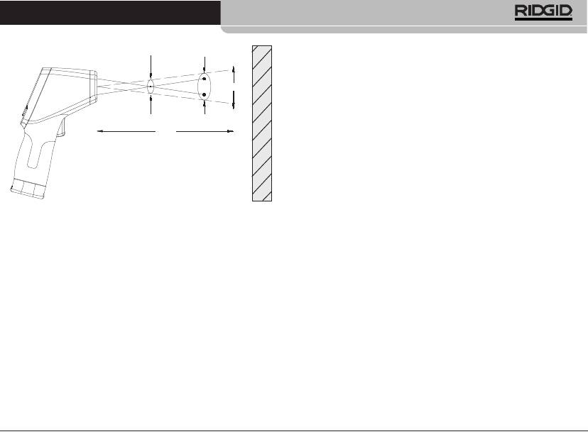
Figure 7 – Champ de vision
Le diamètre de la zone de prise de température doit toujours
sʼinscrire dans la surface mesurée. Plus la surface est petite,
plus il sera nécessaire de se rapprocher dʼelle. Une précision
optimale sera obtenue lorsque la surface mesurée est au moins
deux fois plus grande que la zone de prise de température.
Emissivité – Le terme «émissivité» sert à décrire les carac-
téristiques dʼémission dʼénergie dʼune matière sur une échelle
de 0 à 1. Le micro IR-100 utilise une émissivité fixe de 0,95
pour calculer les températures. Cette valeur est adaptée à la
grande majorité des possibilités dʼutilisation, y compris la ma-
jorité des surfaces peintes.
Les surfaces brillantes ou polies ont une faible émissivité et
produisent des résultats erronés. Un moyen de parer à cet in-
convénient est dʼapposer une bande adhésive sur la surface ou
de peindre la surface en noir mat. Permettez à la bande adhé-
sive ou à la peinture dʼatteindre la température de la surface
avant de prendre la température à cet endroit.
D:S=20:1
25.4mm @
508mm
508mm @
1016mm
S
1.0in@ 20in
2.0in@ 40in
D
Thermomètre infrarouge à distance micro IR-100
Température – Même si le micro IR-100 tient compte des vari-
ations de température ambiante, de grandes variations de tem-
pérature ambiante ou de température mesurée peuvent limiter
sa précision. Afin dʼobtenir un maximum de précision en
présence de variations importantes de température ambiante
(supérieures à 17°C), permettez au micro IR-100 de sʼaccli-
mater pendant une quinzaine de minutes.
Obstacles – Lʼinterposition dʼobstacles tels que vapeur, pous-
Surface
sière, fumée verre ou matières plastiques entre le micro IR-
100 et la surface à mesurer peut nuire à la précision des
relevés. De tels obstacles peuvent occulter lʼoptique de lʼinstru-
ment ou produire des lectures erronées (mesure de la tem-
pérature du verre au lieu de celle de la surface). Ne pas utiliser
cet instrument en présence de tels obstacles.
Tenez compte de ces facteurs avant dʼutiliser le micro IR-100.
3. Assurez-vous quʼune inspection appropriée de lʼensemble du
matériel a bien été effectuée.
Fonctionnement
Activation, désactivation, prises de
température
1. Tenez le micro IR-100 par sa poignée et orientez-le vers la
surface à mesurer. Eloignez-le de tout élément électrique,
mécanique ou brûlant. Assurez-vous que lʼinstrument nʼest
pas orienté vers autrui avant de lʼactiver.
2. Appuyez sur la gâchette pour activer le micro IR-100. En ap-
puyant sur la gâchette, lʼicône SCAN sʼallume et le micro IR-
100 affiche à la fois et en continu la prise de température en
cours et la température maximale relevée depuis lʼactivation
de lʼinstrument.
Ridge Tool Company
25

Thermomètre infrarouge à distance micro IR-100
TIl sʼagit de déplacer le micro IR-100 lentement sur une sur-
surez-vous que lʼinstrument nʼest pas orienté vers autrui avant de
face pour localiser dʼéventuels points chauds ou froids. Re-
lʼactiver. Appuyez sur la gâchette pour activer le micro IR-100. Tout
portez-vous à la section Alarme de température élevée/Alarme
en tenant la gâchette appuyée, appuyez momentanément sur la
de basse température pour de plus amples détails sur lʼutilisa-
touche Menu. Les icônes SCAN et Lock (verrouillage) sʼallumeront.
tion des alarmes haute et basse température.
Lâchez la gâchette, et le micro IR-100 continuera de mesurer la
température actuelle jusquʼà ce que vous appuyez à nouveau mo-
3. Lorsque lʼon lâche la gâchette, lʼicône HOLD sʼallume. Le micro
mentanément sur la gâchette.
IR-100 sʼéteindra automatiquement au bout de sept secondes
sʼil nʼest pas en mode de mesure en continu.
Activation et désactivation du laser
Les lasers de visée peuvent éventuellement être éteints afin dʼaider
micro IR-100 Controls
à conserver la pile. Le cas échéant, il convient de faire particulière-
ment attention lorsque lʼon vise le micro IR-100 afin dʼassurer des
lectures précises. Pour activer ou désactiver les lasers, tenez la
gâchette appuyée, puis appuyez sur la touche Laser. Lorsque le
laser est activé, son icône sʼallume.
Eclairage de fond
Ecran LCD
Lʼécran du micro IR-100 est équipé dʼun éclairage de fond pour
servir dans les endroits mal éclairés. Pour allumer ou éteindre lʼé-
clairage de fond lorsque lʼinstrument est activé, appuyez sur la
touche dʼéclairage de fond.
Utilisation de la touche Menu
Diminuer /
Gâchette
Eclairage de fond
Avec la gâchette appuyée, appuyez momentanément sur la touche
Menu pour naviguer entre les paramètres suivants : activa-
tion/désactivation dʼalarme de température élevée, réglage
Laser
Menu
dʼalarme de température élevée, activation/désactivation dʼalarme
de basse température, réglage dʼalarme de basse température,
unités de mesure de température (dans lʼordre).
Figure 8 – Touches et écran du micro IR-100
Alarme de température élevée
Mesure en continu (scanner)
Lʼalarme de température élevée émettra une tonalité audible dès
Il est possible de verrouiller la gâchette pour que le micro IR-100
que la température présente dépasse une limité préétablie. Pour
prenne des mesures en continu sans avoir à la tenir appuyée. As-
activer lʼalarme de température élevée, appuyez momentanément
26
Ridge Tool Company
Thermomètre infrarouge à distance micro IR-100
sur la gâchette, puis aussi souvent que nécessaire sur la touche
Nettoyage
Menu pour que lʼicône dʼalarme de température élevée sʼaffiche en
Ne jamais immerger le thermomètre infrarouge RIDGID micro IR-
clignotant. Servez-vous des flèches haute et basse pour activer ou
100 dans lʼeau. Essuyez-le à lʼaide dʼun chiffon doux humecté. Ne
désactivé lʼalarme comme indiqué sur la ligne de température
pas utiliser de produits de nettoyage abrasifs. Traitez lʼinstrument
actuelle. Appuyez à nouveau momentanément sur la touche Menu.
comme sʼil sʼagissait dʼun télescope ou dʼun appareil photo.
Lʼicône dʼalarme de température élevée continuera à clignoter et
la température limite sera affichée. Servez-vous des flèches haute
et basse pour régler la température dʼalarme au souhait. Appuyez
Stockage
sur la gâchette pour quitter le mode de réglage et sauvegarder vos
Le thermomètre infrarouge RIDGID micro IR-100 doit être remisé
paramètres.
dans un lieu sec et sécurisé, et à une température ambiante située
entre –10°C (14°F) et 60°C (140°F).
Alarme de basse température
Rangez lʼinstrument dans un endroit sécurisé, hors de la portée
Lʼalarme de basse température émettra une tonalité audible dès
des enfants et de tout individu étranger au fonctionnement du micro
que la température présente tombe en dessous dʼune limité
IR-100.
préétablie. Pour activer lʼalarme de basse température, appuyez
momentanément sur la gâchette, puis aussi souvent que néces-
Afin de parer aux fuites éventuelles, retirez le piles de lʼinstrument
saire sur la touche Menu pour que lʼicône dʼalarme de basse tem-
avant son expédition ou son stockage prolongé.
pérature sʼaffiche en clignotant. Servez-vous des flèches haute et
basse pour activer ou désactivé lʼalarme comme indiqué sur la ligne
Révisions et réparations
de température actuelle. Appuyez à nouveau momentanément sur
la touche Menu. Lʼicône dʼalarme de basse température continuera
AVERTISSEMENT
à clignoter et la température limite sera affichée. Servez-vous des
La sécurité d’emploi du RIDGID micro IR-100 dépend d’un en-
flèches haute et basse pour régler la température dʼalarme au
tretien approprié.
souhait. Appuyez sur la gâchette pour quitter le mode de réglage et
Toute révision ou réparation du micro IR-100 doit être confiée à un
sauvegarder vos paramètres.
réparateur RIDGID agréé.
Unités d’affichage de température (°C ou °F)
Pour obtenir les coordonnées du réparateur RIDGID le plus proche
ou pour toutes questions visant lʼentretien et la réparation de lʼin-
Le thermomètre infrarouge RIDGID micro IR-100 peut afficher les
strument :
températures en degrés Celsius (°C) ou Fahrenheit (°F) au choix.
Pour changer dʼunités dʼaffichage, appuyez momentanément sur la
• Consultez votre distributeur RIDGID.
gâchette, puis momentanément sur la touche Menu aussi souvent
• Consultez les sites www.RIDGID.com ou www.RIDGID.eu pour
quʼil faudra pour que lʼunité de température affichée à lʼécran se
localiser le représentant RIDGID le plus proche.
mette à clignoter. Servez-vous des flèches haute et basse pour
• Consultez les services techniques de RIDGID par mail
changer dʼunités de température affichée. Appuyez sur la gâchette
adressé à rtctechservices@emerson.com, ou, à partir des
pour quitter le mode de réglage et sauvegarder vos paramètres.
Etats-Unis et du Canada, en composant le (800)519-3456.
Ridge Tool Company
27
Thermomètre infrarouge à distance micro IR-100
Recyclage de l’instrument
Recyclage des piles
Certains composants du thermomètre infrarouge RIDGID micro IR-
Pays de la CE : Les piles défectueuses ou hors dʼusage doivent
100 contiennent des matières de valeur susceptibles dʼêtre recy-
être recyclées selon la norme 2006/66/EEC.
clées. Il se peut que certaines des entreprises de recyclage
concernées se trouvent localement. Disposez de ces composants
selon la réglementation en vigueur. Pour de plus amples renseigne-
ments, consultez votre centre de recyclage local.
A lʼattention des pays de la CE : Ne pas jeter les com-
posants électriques à la poubelle !
Selon la norme européenne 2002/96/EC visant les
déchets de matériel électrique et électronique et son ap-
plication vis-à-vis de la législation nationale, tout matériel
électrique non utilisable doit être collecté à part et recyclé dʼune
manière écologiquement responsable.
28
Ridge Tool Company
micro IR-100
Termómetro infrarrojo sin contacto
micro IR-100
ADVERTENCIA
Antes de utilizar este aparato, lea
detenidamente su Manual del Ope-
rario. Pueden ocurrir descargas e-
léctricas, incendios y/o graves les-
Termómetro infrarrojo sin contacto micro IR-100
iones si no se comprenden y siguen
Apunte aquí el número de serie del aparato ubicado en su placa de características.
las instrucciones de este manual.
No. de
serie
Termómetro infrarrojo sin contacto micro IR-100
Índice
Ficha para apuntar el Número de Serie del aparato ...........29
Empleo de los botones del Menú .........................................40
Alarma Alta ...........................................................................40
Simbología de seguridad.......................................................31
Alarma Baja ..........................................................................41
Normas de seguridad general
Escalas de medición térmica: °C ó °F ..................................41
Seguridad en la zona de trabajo ..........................................32
Limpieza..................................................................................41
Seguridad eléctrica...............................................................32
Seguridad personal ..............................................................32
Almacenamiento.....................................................................41
Uso y cuidado del equipo .....................................................32
Servicio y reparaciones.........................................................41
Servicio.................................................................................33
Eliminación del aparato.........................................................42
Normas de seguridad específica
Eliminación de la pila.............................................................42
Seguridad del Termómetro infrarrojo ....................................33
Garantía vitalicia.............................................carátula posterior
Descripción, especificaciones y equipo estándar
Descripción...........................................................................33
* Traducción del manual original
Especificaciones...................................................................34
Piezas y partes .....................................................................35
Íconos en la pantalla LCD ....................................................36
Equipo estándar ...................................................................36
Clasificación del láser............................................................36
Declaración de la FCC ...........................................................36
Compatibilidad electromagnética (CEM) .............................37
Reemplazo o instalación de la pila.......................................37
Inspección previa al funcionamiento ...................................37
Preparativos y funcionamiento
Preparativos .........................................................................38
Funcionamiento
Encendido y apagado (toma de temperaturas) ....................39
Mandos del micro IR-100
Modalidad de medición continua (escanear)........................40
Láser activado/desactivado ..................................................40
Alumbrado de fondo de la pantalla.......................................40
30
Ridge Tool Company
Termómetro infrarrojo sin contacto micro IR-100
Simbología de seguridad
En este manual del operario y en el aparato mismo encontrará símbolos y palabras de advertencia que comunican información de
seguridad importante. En esta sección se explica el significado de estos símbolos.
Este es el símbolo de una alerta de seguridad. Sirve para prevenir al operario de las lesiones corporales que podría sufrir.
Obedezca todas las instrucciones que acompañan a este símbolo de alerta para evitar lesiones o muertes.
PELIGRO
Este símbolo de PELIGRO advierte de una situación de riesgo o peligro que, si no se evita, podría ocasionar muertes o
graves lesiones.
ADVERTENCIA
Este símbolo de ADVERTENCIA advierte de una situación de riesgo o peligro que, si no se evita, podría ocasionar
la muerte o lesiones graves.
CUIDADO
Este símbolo de CUIDADO advierte de una situación de riesgo o peligro que, si no se evita, podría ocasionar lesiones
leves o moderadas
AVISO
Un AVISO advierte de la existencia de información relacionada con la protección de un bien o propiedad.
Este símbolo significa que, antes de usar el aparato, es indispensable leer detenidamente su manual del operario. El manual del
aparato contiene importante información acerca del funcionamiento apropiado y seguro del equipo.
Este símbolo señala que este dispositivo contiene un láser clase 2.
Este símbolo señala que no se debe fijar la vista en el rayo láser.
Este símbolo advierte de la presencia y peligrosidad de un rayo láser.
Ridge Tool Company
31
PRECAUCION
RADIACION LASER
NO MIRE AL RAYO
POTENCIA MAXIMA < 1mw
LONGITUD DE ONDA 630-670 nm
PRODUCTO LASER CLASE 2
EN 60825-1:1994/A11:1996/A2:2001/A1:2002
Termómetro infrarrojo sin contacto micro IR-100
Normas de seguridad general
Seguridad personal
• Manténgase alerta, preste atención a lo que está haciendo
ADVERTENCIA
y use sentido común cuando haga funcionar este aparato.
Lea todas estas advertencias e instrucciones. Pueden ocurrir
No lo use si está cansado o se encuentra bajo la influencia
golpes eléctricos, incendios y/o lesiones corporales graves si
no se siguen todas las instrucciones y respetan las adverten-
de drogas, alcohol o medicamentos. Sólo un breve descuido
cias detalladas a continuación.
mientras hace funcionar el aparato puede ocasionar lesiones
personales graves.
¡GUARDE ESTAS INSTRUCCIONES!
• Use el equipo de protección personal que corresponda.
Si lo desea, puede solicitar la declaración CE de conformidad (890-
Siempre use protección para sus ojos. Al usar mascarilla para
011-320) como complemento independiente de este manual
el polvo, calzado de seguridad antideslizante, casco duro o pro-
tección para los oídos, según las circunstancias, usted evitará
Seguridad en la zona de trabajo
lesionarse.
• Mantenga su zona de trabajo ordenada, limpia y bien ilumi-
• No extienda su cuerpo para alcanzar algo. Mantenga sus
nada. Las áreas oscuras o atestadas de cosas provocan acci-
pies firmes en tierra y un buen equilibrio en todo momento.
dentes.
Así se ejerce mejor control sobre el aparato en situaciones ines-
• No haga funcionar este aparato en presencia de combusti-
peradas.
bles tales como líquidos, gases o polvo inflamables. Este
aparato puede generar chispas, las que podrían inflamar el polvo
Uso y cuidado del equipo
o las emanaciones combustibles.
• No fuerce el aparato. Use el equipo apropiado para la tarea
• Mientras haga funcionar este aparato, mantenga apartados
que realizará. El aparato adecuado hará el trabajo mejor y de
a niños y espectadores. Cualquier distracción puede hacerle
manera más segura, al ritmo para el cual fue diseñado.
perder el control del aparato.
• Si el interruptor del aparato no lo enciende o no lo apaga, no
lo haga funcionar. Cualquier aparato que no pueda ser contro-
Seguridad eléctrica
lado mediante su interruptor es peligroso y debe ser reparado.
• Evite el contacto de su cuerpo con artefactos conectados a
• Extráigale la pila al aparato antes de efectuarle ajustes, de
tierra tales como cañerías, radiadores, estufas o cocinas y
cambiarle accesorios o de guardarlo. Esta medida preventiva
refrigeradores. Aumenta el riesgo de que se produzca un
evita accidentes.
choque eléctrico cuando su cuerpo ofrece conducción a tierra.
• Almacene los aparatos que no estén en uso fuera del
• No exponga este aparato a la lluvia o a la humedad. Si al dis-
alcance de niños y no permita que los hagan funcionar per-
positivo le entra agua, aumenta el riesgo de que ocurran descar-
sonas sin capacitación o que no hayan leído estas instruc-
gas eléctricas.
ciones. Cualquier aparato es peligroso en manos de inexpertos.
32
Ridge Tool Company

Termómetro infrarrojo sin contacto micro IR-100
• Hágale buen mantenimiento a este aparato. Revísele sus
¡GUARDE ESTAS INSTRUCCIONES!
piezas movibles por si están desalineadas o agarrotadas. Cer-
Mantenga este manual junto al aparato, a la mano del operario.
ciórese de que no tenga piezas quebradas y que no existen
condiciones que puedan afectar su buen funcionamiento. Si está
Seguridad del Termómetro infrarrojo
dañado, antes de usarlo, hágalo componer. Los equipos en
malas condiciones causan accidentes.
• No mire el rayo láser. Le hará mal a sus ojos. Tampoco mire el
rayo láser con aparatos ópticos como binoculares o telescopios.
•Utilice este dispositivo y sus accesorios en conformidad
con estas instrucciones, teniendo en cuenta las condi-
• No dirija el rayo láser hacia los demás. Asegure que el rayo
ciones imperantes y las tareas que realizará. Cuando se em-
láser se apunte por encima o por debajo del nivel de los ojos. Los
plea un equipo para efectuar operaciones que no le son propias,
rayos láser pueden ser dañinos para los ojos.
se crean situaciones peligrosas.
• Tome las precauciones pertinentes cuando vaya a trabajar
• Con este aparato, utilice únicamente los accesorios reco-
cerca de objetos eléctricos, en movimiento o calientes. La
mendados por su fabricante. Los accesorios aptos para us-
cercanía a uno de ellos podría causar descargas eléctricas, en-
arse con un aparato determinado pueden resultar peligrosos si
ganches, quemaduras y otras lesiones graves. Es posible que
se utilizan con otros aparatos diferentes.
necesite vestir equipos de seguridad personal.
• Mantenga los mangos y mandos del aparato limpios y secos,
Si tiene cualquier pregunta acerca de este producto de RIDGID:
libres de aceite y grasa. Así se ejerce un mejor control sobre el
• Contacte al distribuidor de RIDGID en su localidad.
aparato.
• Por internet visite el sitio www.RIDGID.com ó www.RIDGID.eu
Servicio
para averiguar dónde se encuentran los centros autorizados de
• El servicio del aparato debe encomendarse únicamente a
RIDGID más cercanos.
un técnico calificado que emplea repuestos idénticos. Así
• Llame al Departamento de Servicio Técnico de RIDGID
se garantiza la continua seguridad del aparato.
desde EE.UU. o Canadá al (800) 519-3456 o escriba a
rtctechservices@emerson.com .
Normas de seguridad específica
Descripción, especificaciones y
ADVERTENCIA
equipo estándar
Esta sección entrega información de seguridad específica
para esta herramienta.
Descripción
Antes de usar este Termómetro infrarrojo sin contacto micro
El Termómetro infrarrojo sin contacto micro IR-100 de RIDGID
®
en-
IR-100, lea estas precauciones detenidamente para evitar le-
trega, con sólo pulsarle un botón, lecturas rápidas y precisas de la
siones oculares y otras de carácter grave.
temperatura que tiene la superficie de un objeto. Usted simple-
mente aprieta el gatillo del aparato y apunta los dos intensos
Ridge Tool Company
33

Termómetro infrarrojo sin contacto micro IR-100
láseres clase II hacia la superficie a la cual se desea tomarle la
Láser diódico ................................Salida <1mW, longitud de
temperatura. El micro IR-100 entrega de inmediato la medición de
onda 630~670nm, producto
la temperatura en su nítida pantalla LCD. Este instrumento com-
láser clase 2
pacto y robusto, además de servir para otras múltiples aplicaciones,
Visualización de la temperatura .....última temperatura,
permite a técnicos en reparaciones diagnosticar problemas de cale-
temperatura MAX
facción y ventilación, realizar revisiones preventivas de motores y
Unidades de medición....................en °Celsius o °Fahrenheit
sistemas eléctricos, detectar averías en trampas de vapor, e in-
Temperatura de funcionamiento.....0 a 50°C (32 a 122°F)
speccionar rápidamente fusibles e interruptores de circuito por si se
están recalentando, sin necesidad de tocar con sus manos super-
Temperatura de almacenamiento...-10 a 60°C (14 a 140°F)
ficie alguna.
Resolución del display....................0,1°C (0,1°F)
El micro IR-100 utiliza la óptica para detectar la energía siendo
Humedad relativa ...........................en funciones 10%~90%,
emitida, reflejada o transmitida, la cual capta y enfoca hacia un
almacenado <80%
detector. El sistema electrónico del aparato traduce los datos y los
Pila..................................................(1) de 9V, NEDA 1604A ó IEC
entrega en la pantalla en grados de temperatura. Los haces laséri-
6LR61, ó equivalente
cos cumplen la función de apuntar.
Protección contra polvo ................hasta 54 IP
Peso .............................................0.3 Kg. (0,6 lbs.)
Especificaciones
Gama térmica mensurable ...........-50°C a 800°C
Características
(-58°F a 1472°F)
• Función de detección rápida
Cociente distancia-objetivo...........20 a 1
• Avistamiento de doble láser Clase II
Exactitud de medición ..................50°C ~20°C (-58°F ~68°F) :
• Sujeción automática de los datos
± 2,5°C (4,5°F)
• Visualización de temperaturas MAX
620°C ~800°C (68°F ~1472°F)
± 1,0% ±1°C (1,8°F)
• Mediciones precisas sin contacto
Reproducibilidad.............................50°C ~20°C (-58°F ~68°F) :
• Distancia de selección y resolución de pantalla automáticas de
±1,3°C (2,3°F)
0,1°C (0,1°F)
68°F ~1472°F (20°C ~800°C)
• Pantalla de cristal líquido (LCD) con alumbrado de fondo
±0,5% ó ± 0,5°C (0,9°F)
• Traba para el gatillo
Tiempo de respuesta .....................150 ms
• Alarmas de alta y baja establecidas
Respuesta espectral ......................8~14um
Emisividad......................................fija, 0,95
Indicación de superposición
de gamas........................................pantalla LCD mostrará “----”
34
Ridge Tool Company

Termómetro infrarrojo sin contacto micro IR-100
Piezas
Pantalla LCD
Botón de flecha
ascendente y de
Botón de flecha
Activar el láser
descendente y
del alumbrado
Gatillo
de fondo
Botón de Menú
Empuñadura
Compartimiento
de la pila
Figura 1 – Termómetro infrarrojo sin contacto micro IR-100
Figura 2 – Piezas del micro IR-100
Sensor infrarrojo
Láser
Láser
Gatillo
Ridge Tool Company
35
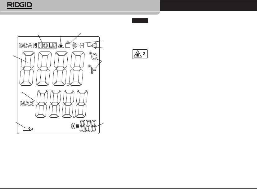
Termómetro infrarrojo sin contacto micro IR-100
Íconos en la pantalla
AVISO
Este aparato sirve para medir temperaturas. Su apli-
cación o uso incorrecto puede ocasionar mediciones inexactas o
Sujeción de
datos (HOLD)
erróneas. Es responsabilidad del usuario seleccionar los métodos
Activar láser
Candado
adecuados de medición según las condiciones imperantes.
Alarma
Alta (H)
Clasificación del láser
Alarma
Temperatura
Baja (L)
El micro IR-100 de RIDGID genera haces laséricos visi-
actual
bles emitidos desde la parte delantera del aparato.
Escalas de
El dispositivo cumple con las normas de láseres clase 2 en concor-
medición
dancia con: EN 60825- 1:199/A11: 1996/A2:2001/A1:2002
térmica
(°C ó °F)
Declaración de la FCC
Este aparato ha sido sometido a pruebas y se encuentra dentro de
Temperatura
los parámetros exigidos a un dispositivo digital de Clase B, de con-
máxima
formidad con el apartado 15 de las Normas de la agencia federal
FCC. Estos límites otorgan una protección razonable contra inter-
ferencias perjudiciales en una instalación residencial.
Este aparato genera, utiliza y puede irradiar energía de radiofre-
cuencia y, si no se instala y utiliza de acuerdo con las instrucciones,
Pila con
puede causar interferencias perjudiciales a las comunicaciones de
baja
Emisividad
radio.
carga
Sin embargo, no puede garantizarse que no ocurrirán interferen-
cias en funa determinada instalación.
Figura 3 – Íconos en la pantalla del micro IR-100
Si este aparato llegara a causar interferencias dañinas sobre la re-
cepción de señales de radio o televisión, las que pueden detec-
tarse apagando y prendiendo el aparato, el usuario debe intentar
Equipo estándar
eliminar la interferencia tomando una o más de las siguientes me-
• micro IR-100
• Pila de 9V (1)
didas:
• Estuche del aparato
• Manual del operario
• Reorientar o reubicar la antena receptora.
• Aumentar la distancia entre el equipo y el receptor.
• Consultar al distribuidor o a un técnico de radio y televisión para
obtener ayuda.
36
Ridge Tool Company
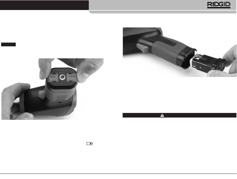
Termómetro infrarrojo sin contacto micro IR-100
Compatibilidad electromagnética (CEM)
2. Instale una nueva pila alcalina de 9V (6LR61), fijándose bien
en la polaridad indicada en el portapila.
Se entiende por compatibilidad electromagnética la capacidad del
producto para funcionar sin problemas en un entorno donde exis-
ten radiación electromagnética y descargas electroestáticas, sin
causarle interferencia electromagnética a otros equipos.
AVISO
El micro IR-100 RIDGID cumple con todas las normas
CEM pertinentes. Sin embargo, no se puede descartar del todo la
posibilidad de que cause interferencias en otros dispositivos.
Figura 5 – Portapila y marcas de polaridad
3. Apriete los clips en el cabezal del portapila e introdúzcalo en el
aparato. El portapila entra en el compartimiento de pila de una
sola manera. No lo fuerce. Revise que quedó bien asentado.
Inspección previa al funcionamiento
ADVERTENCIA
Antes de cada uso, inspeccione el Termómetro infrarrojo y solu-
Figura 4 – Extracción del compartimiento de la pila
cione cualquier problema que pudiera ocasionar lesiones o lec-
turas erróneas.
Reemplazo o instalación de la pila
No mire el rayo láser directamente. Esto es peligroso para sus
ojos.
El micro IR-100 se suministra con una pila instalada. Si el indicador
del nivel de carga de la pila (Figura 3) muestra , se necesita
1. Quite el aceite, grasa o mugre del aparato para facilitar su ins-
reemplazar la pila. Extráigale la pila antes de almacenar el aparato
pección.
por un período prolongado, para evitar que la pila tenga fugas.
2. Revise el Termómetro micro IR-100 para asegurar que no le
1. Apriete los clips en el cabezal del portapila y extráigalo del
faltan piezas, no tiene partes quebradas, desgastadas, desali-
aparato (vea la Figura 4). Extraiga la pila que tiene dentro.
neadas o trabadas, o por si existe cualquiera otra condición
que pueda afectar su funcionamiento normal y seguro.
Ridge Tool Company
37
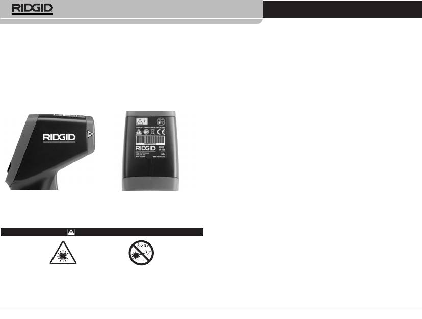
Termómetro infrarrojo sin contacto micro IR-100
3. Revise que las etiquetas de advertencias estén bien pegadas
No dirija el haz lasérico hacia los demás. Asegure que el rayo
láser se apunte por encima o por debajo del nivel de sus ojos.
al aparato y legibles. (Vea la Figura 6).
Los rayos láser pueden ser peligrosos para los ojos.
4. Si detecta cualquier problema, no use el Termómetro infrarrojo
Tome las precauciones pertinentes cuando vaya a trabajar
hasta que no haya sido debidamente reparado.
cerca de objetos eléctricos, en movimiento o calientes. La cer-
canía a uno de éstos podría causar descargas eléctricas, en-
5. Siguiendo las instrucciones de Funcionamiento del aparato,
ganches, quemaduras y otras lesiones graves. Es posible que
enciéndalo, efectúe una medición y confirme esta misma me-
necesite vestir equipos de seguridad personal.
dida con otro instrumento (termómetro de contacto u otro). Si
las mediciones no guardan correlación entre ellas, no utilice el
Prepare y haga funcionar el Termómetro infrarrojo de acuerdo
a los siguientes procedimientos, con el fin de prevenir lesiones
Termómetro infrarrojo hasta que haya sido reparado.
y mediciones incorrectas.
Preparativos
1. Busque situarse en una zona apropiada, como se indica en la
sección Normas de seguridad general.
2. Revise el objetivo cuya temperatura medirá y cerciórese de que
usted dispone del equipo correcto para efectuar esta tarea.
Consulte la sección Especificaciones para verificar el alcance,
precisión y otras características de este instrumento.
Una serie de factores podrían afectar la precisión de las
mediciones del micro IR-100, entre ellos:
Figura 6 – Etiquetas de advertencias
Campo visual: El micro IR-100 emplea dos láseres para apun-
tar hacia ambos lados de la zona que se medirá. Estos puntos
Preparativos y funcionamiento
indican el diámetro aproximado del área (el “Sitio”) en la que se
medirá la temperatura. A medida que el micro IR-100 se aleja
ADVERTENCIA
(D) de la superficie, el tamaño de esta área y del sitio (S) au-
menta. El área es aproximadamente 0,05 veces la distancia
hasta la superficie (Figura 7).
No mire el haz lasérico directamente, puede herir sus ojos.
Nunca mire un rayo láser con aparatos ópticos como anteojos
de larga vista o telescopios.
38
Ridge Tool Company
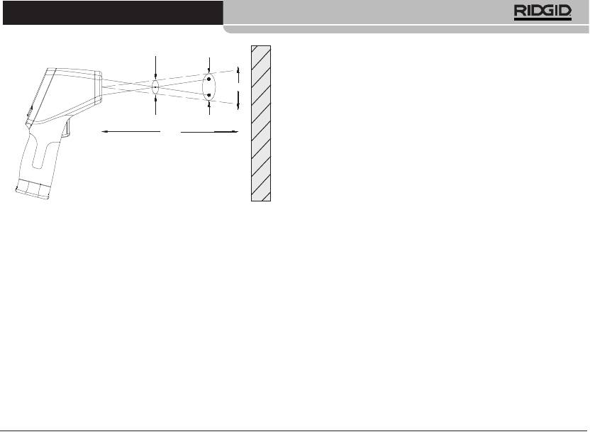
Figura 7 – Campo visual
El Sitio debe ser siempre más pequeño que la superficie. Mien-
tras más reducida la superficie, más cerca debería estar el
micro IR-100 de la superficie. Para obtener la mayor precisión,
la superficie debe ser dos veces más amplia que el Sitio.
Emisividad: es el término que se emplea para describir las
características de la radiación (poder emisor) emitida por la
superficie de un material, cuyo valor oscila entre 0 y 1. El micro
IR-100 utiliza una emisividad de 0,95 para calcular temperat-
uras. Este valor es apropiado para la gran mayoría de aplica-
ciones, incluyendo la mayoría de las superficies pintadas.
Las superficies brillantes o pulidas tienen una emisividad baja
y darán lecturas inexactas. Una forma de compensar esto es
pegar cinta adhesiva o pintura negra mate (sin brillo) a la su-
perficie. Permita que la cinta o la pintura alcancen la misma
temperatura que la superficie y proceda a medir la temperatura
de la cinta o de la pintura.
D:S=20:1
25.4mm @
508mm
508mm @
1016mm
S
1.0in@ 20in
2.0in@ 40in
D
Termómetro infrarrojo sin contacto micro IR-100
Temperatura: Si bien el micro IR-100 compensa las varia-
25,4mm @ 508 mm
508mm @ 1016 mm
ciones a partir de la temperatura ambiente, los cambios signi-
ficativos en las temperaturas ambiente y en las medidas
pueden reducir la exactitud. Cuando ocurran cambios de gran
magnitud en la temperatura ambiente (más de 17°C ó 30°F),
espere 15 minutos para que el micro IR-100 efectúe los ajustes
necesarios para mejorar su exactitud.
1,0 plugs. @ 20 plugs.
2,0 plugs. @ 40 plugs.
Obstrucciones: El vapor, polvo, humo u otras obstrucciones
Superficie
-como el vidrio o el plástico- que se encuentren entre el micro
IR-100 y la superficie que se está midiendo, pueden hacer dis-
minuir la exactitud. Éstos obstruyen la óptica del aparato o dan
lecturas falsas (se mide la temperatura del vidrio en vez de la
superficie). No utilice el aparato si hay obstrucciones presentes.
Tenga en cuenta estos factores obstructivos antes de tomar
temperaturas con el micro IR-100.
3. Asegure que el aparato ha sido revisado correctamente.
Funcionamiento
Encendido y apagado (toma de temperaturas)
1. Tome el micro IR-100 por su empuñadura y apúntelo hacia la
superficie cuya temperatura desea medir. Apártese de obje-
tos eléctricos, móviles o calientes. Antes de encender y apun-
tar el aparato en la dirección deseada, asegure que no se
encuentre nadie en la trayectoria del haz lasérico.
2. Apriete el gatillo para encender el micro IR-100. Cuando se
apriete el gatillo, el ícono de SCAN estará encendido y el micro
IR-100 irá actualizando continuamente los grados de la tempe-
ratura actual en la pantalla. Asimismo, debajo de estos valores
térmicos “en curso”, aparecerá en la pantalla -junto al símbolo
MAX- la temperatura máxima medida desde que se encendió
el aparato.
Ridge Tool Company
39
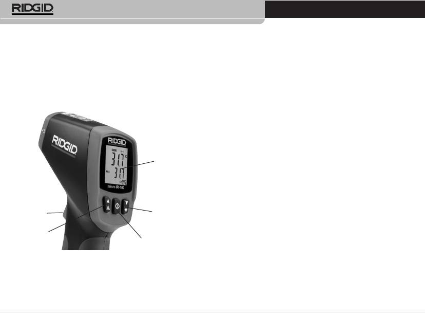
Termómetro infrarrojo sin contacto micro IR-100
Es posible mover el micro IR-100 lentamente por sobre la su-
vaya a apuntar en dirección a algún transeúnte. Apriete el gatillo y
perficie para localizar zonas calientes o frescas. Vea las sec-
manténgalo oprimido para encender el micro IR-100. Mientras lo
ciones de Alarma Alta y Alarma Baja para saber regularlas.
mantiene apretado, oprima y suelte el botón de Menú. Verá encen-
didos los íconos de SCAN y del candado (cerrado). Suelte el gatillo
3. Cuando se suelte el gatillo, el ícono de HOLD (Sujeción de
y el micro IR-100 irá mostrando continuamente las temperaturas
datos) estará encendido. El micro IR-100 se apagará automáti-
que ha ido midiendo hasta que al gatillo se le vuelva a apretar y
camente en un lapso de siete segundos, salvo que el aparato
soltar.
se encuentre en la modalidad de Medición continua.
Láser activado/desactivado
Mandos del micro IR-100
Para conservar la carga de la pila, pueden apagarse los láseres,
empleados para apuntar. Pero si se apagan, debe tenerse especial
cuidado al apuntar el micro IR-100 con el fin de lograr buenas
mediciones. Para activar o desactivar los haces laséricos, mientras
aprieta el gatillo, oprima y suelte el botón de Activar el láser. El ícono
de láser activado aparecerá encendido en la pantalla.
Pantalla LCD
Alumbrado de fondo de la pantalla
Si utilizará el IR-100 en una zona oscura, su pantalla cuenta con
alumbrado de fondo. Para encenderlo o apagarlo, estando el
aparato encendido, oprima el botón del alumbrado de fondo.
Funciones del botón de Menú
Botón de flecha
Gatillo
descendente y
Habiendo apretado el gatillo, oprima y suelte el botón de Menú:
de alumbrado
éste le permite recorrer las siguientes posiciones, en este orden:
de fondo
ON/OFF de la Alarma Alta, valor térmico fijado para Alarma Alta,
Láser
ON/OFF de la Alarma Baja, valor térmico fijado para Alarma Baja,
Botón de Menú
escala térmica deseada.
Figura 8 – Botones de ajuste de la pantalla del micro IR-100
Alarma Alta
La Alarma Alta sonará cuando la temperatura del momento o ac-
Modalidad de medición continua (escanear)
tual excede el límite predeterminado. Para encender la Alarma Alta
El micro IR-100 se le puede “trabar” para que efectúe mediciones
apriete y suelte el gatillo; luego oprima y suelte el botón de Menú
sin que haya que mantener el dedo cargado en su gatillo. Nueva-
hasta que el ícono de laAlarma Alta parpadee. Emplee los botones
mente fíjese, antes de encender el aparato, en que el rayo láser no
de flecha ascendente y descendente para encender o apagar la
40
Ridge Tool Company

Termómetro infrarrojo sin contacto micro IR-100
Alarma Alta lo cual va siendo indicado en la línea de la temper-
Limpieza
atura actual. De nuevo oprima y suelte el botón de Menú. El ícono
No sumerja el Termómetro infrarrojo sin contacto micro IR-100 de
deAlarmaAlta continuará parpadeando y aparecerá la temperatura
RIDGID en agua. Quítele la mugre con un paño húmedo suave.
de Alarma Alta que había sido fijada anteriormente. Utilice los
No emplee agentes de limpieza fuertes ni disolventes. Cuide este
botones de flecha ascendente y descendente para cambiar la tem-
instrumento como si fuese un telescopio o cámara.
peratura de Alarma Alta por la que usted desee. Apriete el gatillo
para salir de la modalidad de configuración y guardar su selección.
Almacenamiento
Alarma Baja
Guarde el Termómetro infrarrojo micro IR-100 de RIDGID en un
La Alarma Baja sonará cuando la temperatura del momento o ac-
lugar seguro y seco a temperaturas entre -10 a 60°C (14 a 140°F).
tual es inferior al límite predeterminado. Para encender la Alarma
Almacénelo bajo llave fuera del alcance de niños y personas que
Baja apriete y suelte el gatillo; luego oprima y suelte el botón de
no saben usarlo.
Menú hasta que el ícono de la Alarma Baja parpadee. Emplee los
botones de flecha ascendente y descendente para encender o apa-
Extráigale su pila si lo va a guardar por un período prolongado de
gar la Alarma Baja como se indica en la línea de la temperatura ac-
tiempo o lo va a enviar por encomienda. La pila puede perder
tual. De nuevo oprima y suelte el botón de Menú. El ícono de
líquido.
Alarma Baja continuará parpadeando y aparecerá la temperatura
anteriormente fijada de Alarma Baja. Utilice los botones de flecha
Servicio y reparaciones
ascendente y descendente para cambiar la temperatura de Alarma
Baja por otra que usted prefiera. Apriete el gatillo para salir de la
ADVERTENCIA
modalidad de configuración y guardar su selección.
El Termómetro infrarrojo sin contacto micro IR-100 de RIDGID
puede tornarse inseguro si se le repara o mantiene incorrecta-
Escalas de medición térmica: °C ó °F
mente.
El micro IR-100 puede mostrar temperaturas ya sea en grados Cel-
El servicio y reparaciones del micro IR-100 deben confiarse única-
sius (C) o Fahrenheit (F). Para cambiar la escala que se muestra en
mente a un Servicentro Autorizado de RIDGID.
pantalla, apriete y suelte el gatillo; luego pulse y suelte el botón de
Para obtener información acerca del Servicentro Autorizado
Menú hasta que la escala de medición térmica deseada parpadee
RIDGID más cercano a su localidad o consultar sobre el servicio
en la pantalla. Utilice los botones de flecha ascendente y descen-
o reparación de este aparato:
dente para cambiar entre °C y °F. Apriete el gatillo para salir de la
modalidad de configuración y guardar su selección.
• Contacte al distribuidor RIDGID en su localidad.
• En internet visite el sitio www.RIDGID.com ó www.RIDGID.eu
para averiguar dónde se encuentran los centros autorizados de
RIDGID más cercanos.
Ridge Tool Company
41
Termómetro infrarrojo sin contacto micro IR-100
• Llame al Departamento de Servicio Técnico de RIDGID
Eliminación de la pila
desde EE.UU. o Canadá al (800) 519-3456 o escriba a
En la CE: Las pilas usadas o defectuosas deben reciclarse con-
rtctechservices@emerson.com .
forme a la directriz 2006/66/EC.
Eliminación del aparato
Piezas y partes del Termómetro infrarrojo sin contacto micro IR-100
de RIDGID están fabricadas de materiales de valor, posibles de re-
ciclar. Averigüe cuáles empresas se especializan en reciclaje en su
localidad. Deseche el aparato o sus componentes cumpliendo con
todas y cada una de las disposiciones vigentes en su jurisdicción.
Para mayor información, llame a la agencia local encargada de la
eliminación de residuos sólidos.
En los países miembros de la Comunidad Europea
(CE): ¡No se deshaga de equipos eléctricos junto con la
basura doméstica!
Según la directriz de la Comunidad Europea 2002/96/EC,
impartida a sus países miembros sobre desechos eléctri-
cos y electrónicos, los equipos eléctricos inutilizables deben ser
recolectados en forma separada de la basura municipal y elimina-
dos sin causar daños al medio ambiente.
42
Ridge Tool Company

micro IR-100
micro IR-100
Kontaktloses Infrarotthermometer
WARNUNG
Lesen Sie diese Be die nungs-
an lei tung sorgfältig, bevor Sie
dieses Gerät benutzen. Unken-
ntnis und Nichtbefolgung des
micro IR-100 Kontaktloses Infrarotthermometer
In halts die ser Anleitung kön-
nen zu elektrischen Schlägen,
Notieren Sie unten die Seriennummer und bewahren Sie diese auf. Sie
finden die Produkt-Seriennummer auf dem Typenschild.
Feuer und/oder schweren Ver-
letzungen führen.
Serien-
nr.

micro IR-100 Kontaktloses Infrarotthermometer
Inhaltsverzeichnis
Benutzung der Menütaste ......................................................................... 54
Alarm bei hohen Temperaturen ............................................................... 54
Formular zum Festhalten der Geräteseriennummer .......................43
Alarm bei niedrigen Temperaturen ........................................................ 54
Temperaturanzeigeeinheiten C/F ........................................................... 54
Sicherheitssymbole .......................................................................................... 45
Reinigung .............................................................................................................. 55
Allgemeine Sicherheitsregeln
Sicherheit im Arbeitsbereich ....................................................................46
Aufbewahrung .................................................................................................... 55
Elektrische Sicherheit ..................................................................................46
Wartung und Reparatur ................................................................................. 55
Sicherheit von Personen ............................................................................. 46
Entsorgung ........................................................................................................... 55
Sachgemäßer Umgang mit dem Gerät ................................................. 46
Wartung ............................................................................................................ 47
Entsorgung von Akkus ...................................................................................... 55
Spezielle Sicherheitshinweise
Garantie ..................................................................................................Rückseite
Sicherheitshinweise für Infrarotthermometer .................................... 47
* Übersetzung der Originalbetriebsanleitung
Beschreibung, technische Daten und Standardausstattung
Beschreibung .................................................................................................. 47
Technische Beschreibung ..........................................................................48
Teile .................................................................................................................... 49
Symbole LCD-Display ..................................................................................49
Standardausstattung ................................................................................... 49
Laser-Klassifizierung .......................................................................................50
FCC-Erklärung ..................................................................................................... 50
Elektromagnetische Verträglichkeit (EMV) ..........................................50
Wechseln/Einsetzen der Batterien ............................................................50
Kontrolle vor dem Betrieb ............................................................................. 51
Vorbereitung und Betrieb
Setup..................................................................................................................52
Betrieb
Ein- und Ausschalten (Messungen durchführen) .............................. 53
micro IR-100 Bedienelemente
Dauermessmodus (Scannen) .................................................................... 54
Laser aktiviert/deaktiviert .......................................................................... 54
Hintergrundbeleuchtung ........................................................................... 54
44
Ridge Tool Company
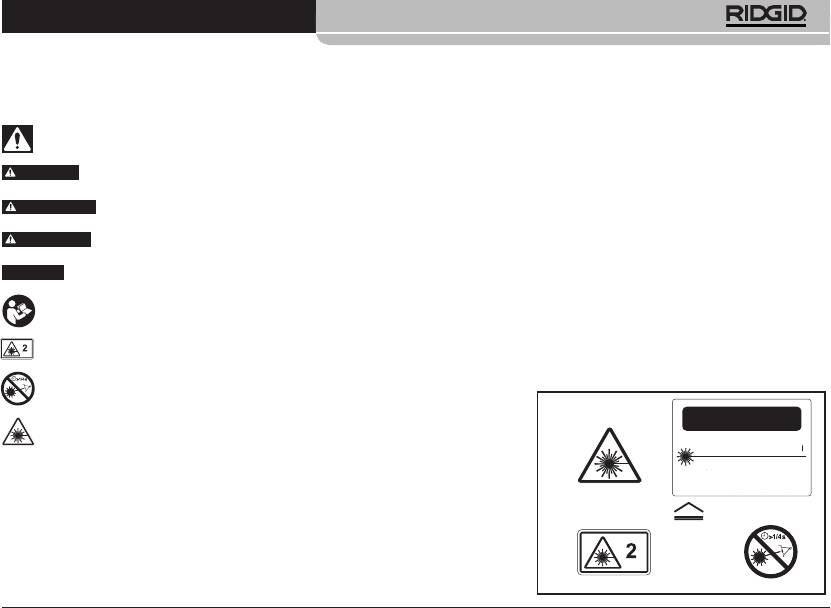
micro IR-100 Kontaktloses Infrarotthermometer
Ridge Tool Company
45
ACHTUNG
LASERSTRAHLUNG
NICHT IN DEN LASERSTRAHL BLICKEN
MAXIMALE LEISTUNG < 1mW
WELLENLÄNGE 630-670 nm
KLASSE 2 LASER
EN 60825-1:1994/A11:1996/A2:2001/A1:2002
Sicherheitssymbole
Wichtige Sicherheitshinweise werden in dieser Bedienungsanleitung und auf dem Produkt mit bestimmten Sicherheitssymbolen und Warnungen
gekennzeichnet. Dieser Abschnitt enthält Erläuterungen zu diesen Warnhinweisen und Symbolen.
Dies ist das allgemeine Gefahren-Symbol. Es weist auf mögliche Verletzungsgefahren hin. Beachten Sie alle Hinweise mit diesem Symbol,
um Verletzungs- oder Lebensgefahr zu vermeiden.
GEFAHR
GEFAHR weist auf eine gefährliche Situation hin, die ohne entsprechende Sicherheitsvorkehrungen zu Lebensgefahr oder schwe-
ren Verletzungen führt.
WARNUNG
WARNUNG weist auf eine gefährliche Situation hin, die ohne entsprechende Sicherheitsvorkehrungen zu Lebensgefahr oder
schweren Verletzungen führen kann.
ACHTUNG
ACHTUNG weist auf eine gefährliche Situation hin, die ohne entsprechende Sicherheitsvorkehrungen zu kleineren bis mittel-
schweren Verletzungen führen kann.
HINWEIS
HINWEIS kennzeichnet Informationen, die sich auf den Schutz des Eigentums beziehen.
Dieses Symbol bedeutet, dass die Bedienungsanleitung sorgfältig durchzulesen ist, bevor das Gerät in Betrieb genommen wird. Die
Bedienungsanleitung enthält wichtige Informationen für den sicheren, ordnungsgemäßen Gebrauch des Geräts.
Dieses Symbol bedeutet, dass dieses Gerät einen Klasse-2-Laser enthält.
Dieses Symbol bedeutet, dass man nicht direkt in den Laserstrahl blicken darf.
Dieses Symbol macht auf Vorhandensein und Gefahren eines Laserstrahls
aufmerksam.
micro IR-100 Kontaktloses Infrarotthermometer
Medikamenten. Durch einen kurzen Moment der Unaufmerksamkeit
Allgemeine Sicherheitsregeln
können Sie sich selbst oder anderen erhebliche Verletzungen zufügen.
• TragenSie persönlicheSchutzausrüstung. Tragen Sie immer einen
WARNUNG
Augenschutz. Das Tragen einer Schutzausrüstung, wie Staubmaske,
Lesen Sie alle Sicherheitshinweise und Anweisungen in dieser Bet-
rutschfeste Sicherheitsschuhe, Schutzhelm oder Gehörschutz, verrin-
riebsanleitung. Die Nichtbeachtung der nachstehend aufgeführten
gert das Risiko von Verletzungen.
Warnhinweise und Anweisungen kann zu Stromschlag, Brand und/oder
• LehnenSiesichnichtzuweitineineRichtung.SorgenSiestetsfür
schweren Verletzungen führen.
ein sicheres Gleichgewicht und einen festen Stand. Dadurch können
Sie das Gerät in unerwarteten Situationen besser kontrollieren.
BEWAHREN SIE DIESE ANLEITUNG AUF!
Die CE-Konformitätserklärung (890-011-320) kann diesem Handbuch auf
Sachgemäßer Umgang mit dem Gerät
Wunsch als separates Heft beigelegt werden.
• ÜberbeanspruchenSiedasGerätnicht.VerwendenSieimmerein
für den Einsatzbereich geeignetes Gerät. Mit dem richtigen Gerät
Sicherheit im Arbeitsbereich
können Sie Ihre Arbeit effektiver und sicherer ausführen.
• HaltenSieIhrenArbeitsbereichsauber,undsorgenSiefüreinegute
• VerwendenSiedasGerätnicht,wennesnichtübereinenSchalter
Beleuchtung. Unaufgeräumte und unzureichend beleuchtete Arbeits-
ein- und ausgeschaltet werden kann. Ein Werkzeug, das sich nicht
bereiche erhöhen das Unfallrisiko.
über einen Schalter ein- und ausschalten lässt, stellt eine Gefahrenquelle
• BetreibenSiedasGerätnichtinUmgebungenmiterhöhterExplo
dar und muss repariert werden.
sionsgefahr,indenensichleichtentflammbareFlüssigkeiten,Gase
• EntfernenSiedieBatterienausdemGerät,bevorSieEinstellungen
oder Staub befinden. Das Gerät kann im Betrieb Funken erzeugen,
vornehmen, Zubehörteile wechseln oder das Gerät lagern.
durch die sich Staub oder Dämpfe leicht entzünden können.
Durch solche Vorsichtsmaßnahmen wird das Risiko von Verletzungen
• Sorgen Sie beim Betrieb des Geräts dafür, dass sich keine Kin
verringert.
der oder sonstige Unbeteiligte in dessen Nähe befinden. Bei
• Bewahren Sie unbenutzte Geräte außerhalb der Reichweite von
Ablenkungen kann die Kontrolle über das Gerät verloren gehen.
Kindern auf, und lassen Sie Personen, die mit dem Gerät nicht ver-
traut sind oder diese Anweisungen nicht gelesen haben, das Gerät
Elektrische Sicherheit
nicht benutzen. Das Gerät kann gefährlich sein, wenn es von unerfah-
• Vermeiden Sie Körperkontakt mit geerdeten Oberflächen, wie
renen Personen benutzt wird.
Rohren,Heizungen,HerdenundKühlschränken.Es besteht eine er-
• Das Gerät muss regelmäßig gewartet werden. Stellen Sie sicher,
höhte Stromschlaggefahr, wenn Ihr Körper geerdet ist.
dass sich alle beweglichen und festen Teile in der richtigen Position
• HaltenSiedasGerätvonRegenundNässefern.Wenn Wasser in das
befinden, keine Teile fehlen oder gebrochen sind oder sonstige Fehler
Gerät eindringt, erhöht sich das Risiko eines Stromschlags.
vorliegen, die die Funktion des Geräts beeinträchtigen können. Bei
Beschädigungen muss das Gerät vor einer erneuten Verwendung zu-
Sicherheit von Personen
nächst repariert werden. Viele Unfälle werden durch schlecht gewartete
• Seien Sie beim Betrieb des Geräts immer aufmerksam und ver-
Geräte verursacht.
antwortungsbewusst. Verwenden Sie das Gerät nicht, wenn
• VerwendenSiedasGerätundZubehörgemäßdiesenAnweisungen
Sie ermüdet sind oder unter Einfluss von Drogen, Alkohol oder
undunterBerücksichtigungderArbeitsbedingungenundderaus-
46
Ridge Tool Company

micro IR-100 Kontaktloses Infrarotthermometer
zuführendenTätigkeit.Wenn Geräte nicht vorschriftsmäßig verwen-
ger Kontakt kam zum Stromschlägen, Verfangen, Verbrennungen und
det werden, kann dies zu gefährlichen Situationen führen.
anderen schweren Verletzungen führen. Eventuell ist Schutzausrüstung
• VerwendenSiefürdasGerätnurdievomHerstellerempfohlenen
erforderlich.
Zubehörteile. Zubehörteile, die für ein Gerät passend sind, können
Falls Sie Fragen zu diesem RIDGID Produkt haben:
beim Einsatz in einem anderen Gerät zu einer Gefahr werden.
• HaltenSiedieGriffetrocken,sauberundfreivonÖlenundFetten.
• WendenSiesichanIhrenörtlichenRIDGIDHändler.
Dadurch können Sie das Gerät besser bedienen.
• Unterwww.RIDGID.comoderwww.RIDGID.eufindenSieIhreörtliche
RIDGID Kontaktstelle.
Wartung
• WendenSiesichandieAbteilungTechnischerKundendienstvonRIDGID
• LassenSieIhrGerätnurvonqualifiziertemFachpersonalundnur
mit OriginalErsatzteilen reparieren. Dadurch bleibt die Sicherheit
unter rtctechservices@emerson.com oder in den USA und Kanada tele-
des Werkzeugs gewährleistet.
fonisch unter (800) 519-3456.
Spezielle Sicherheitshinweise
Beschreibung, technische Daten und
Standardausstattung
WARNUNG
Beschreibung
Dieser Abschnitt enthält wichtige Sicherheitshinweise, die speziell für
dieses Werkzeug gelten.
Der RIDGID® micro IR-100 kontaktfreie Infrarotthermometer ermöglicht
auf Knopfdruck simple, schnelle und genaue Messungen der Ober-
Lesen Sie diese Sicherheitshinweise sorgfältig, bevor Sie das RIDGID®
flächentemperatur. Man betätigt einfach den Auslöser und richtet den
micro IR-100 kontaktfreie Infrarotthermometer benutzen, um die Gefahr
scharfen Doppel-Laser der Klasse II auf die zu messende Oberfläche. Das
von Feuer, Explosion oder anderen schweren Verletzungen zu mindern.
micro IR-100 zeigt die gemessene Temperatur sofort auf einem gut ables-
BEWAHREN SIE DIESE ANLEITUNG AUF!
baren LCD-Display mit Hintergrundbeleuchtung an. Neben zahlreichen
anderen Einsatzmöglichkeiten bietet dieses robuste, kompakte Instrument
Bewahren Sie diese Bedienungsanleitung beim Gerät auf, damit sie dem
dem Profi die Möglichkeit, Heizungs- und Lüftungsprobleme zu diagnosti-
Bediener jederzeit zur Verfügung steht.
zieren, die vorbeugende Überwachung von Elektromotoren und Systemen
durchzuführen, die Fehlersuche bei Kondensatsabscheidern vorzuneh-
Sicherheitshinweise für Infrarotthermometer
men und Sicherungen oder Schutzschalter kontaktlos auf Überhitzung zu
• Blicken Sie nicht in den Laserstrahl. In den Laserstrahl zu blicken,
überprüfen.
kann die Augen schädigen. Blicken Sie nicht mit optischen Hilfsmitteln
(Fernglas oder Fernrohr) auf den Laserstrahl.
Das micro IR-100 arbeitet mit Optik, um abgestrahlte, reflektierte und über-
• RichtenSiedenLaserstrahlnichtaufanderePersonen.Vergewissern
tragene Energie zu messen, die gesammelt und auf einen Detektor
Sie sich, dass der Laser auf einen Punkt über oder unter Augenhöhe ge-
fokussiert wird. Die Elektronik des Geräts übersetzt die Informationen
richtet wird. Laserstrahlen können schädlich für die Augen sein.
in einer Temperaturmessung, die angezeigt wird. Zur Unterstützung
• TreffenSiebeiderArbeitinderNähevonelektrischen,bewegen-
des Zielens werden Laser eingesetzt.
denoderheißenTeilen entsprechendeVorsichtsmaßnahmen.En-
Ridge Tool Company
47
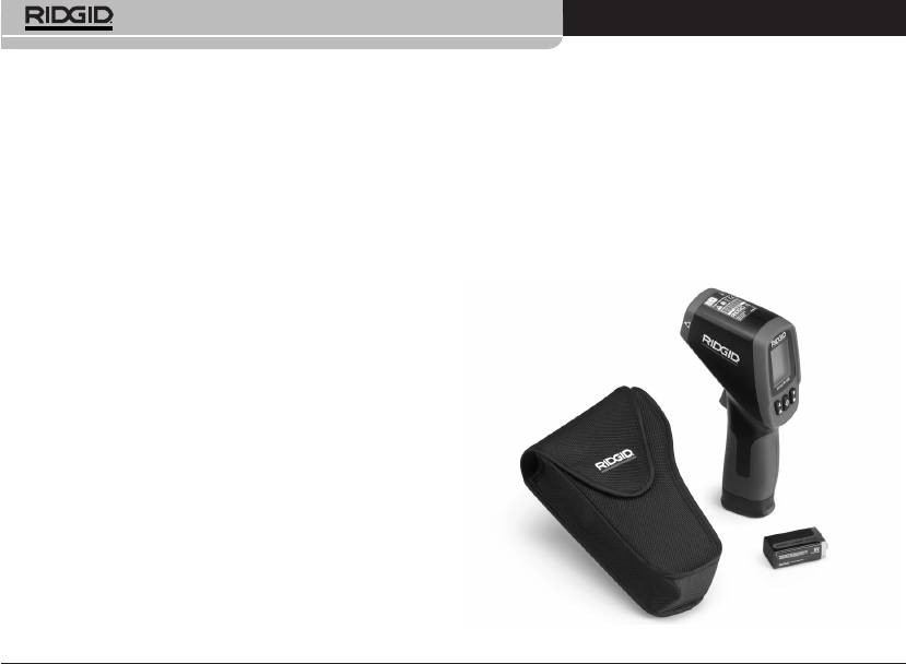
micro IR-100 Kontaktloses Infrarotthermometer
Technische Beschreibung
Merkmale
• Schnellerkennungsfunktion
• Automatischer
Temperaturbereich............................................ -50°C bis 800°C (-58°F bis 1472°F)
Auswahlbereich und
• DualesKlasseIILaser-Visier
Anzeigeauflösung 0,1°C
Verhältnis Distanz/Punkt................................. 20 zu 1
• Automatische
(0,1°F)
Datenerfassung
Messgenauigkeit................................................ 50°C ~20°C (-58°F ~68°F): ± 2,5°C
• LCD-Displaymit
(4,5°F) 20°C ~800°C (68°F ~1472°F)
• Anzeigeder
Hintergrundbeleuchtung
±1,0% oder ± 1,0°C (1,8°F)
Maximaltemperatur
Wiederholbarkeit............................................... 50°C ~20°C (-58°F ~68°F): ± 1,3°C
• Auslösersperre
• Präzisekontaktlose
(2,3°F) 20°C ~800°C (68°F ~1472°F)
• EinstellungvonAlarmen
±0,5% oder ± 0,5°C (0,9°F)
Messungen
für zu hohe und zu niedrige
Reaktionszeit....................................................... 150ms
Temperatur
Spektralreaktion................................................. 8~14um
Emissionsgrad..................................................... Festgelegt, 0,95
Anzeige bei Bereichsüberschreitung......... LCD zeigt “----”
Diodenlaser.......................................................... Leistung <1mW, Wellenlänge
630~670nm, Laserprodukt Klasse 2
Temperaturanzeige........................................... Aktuelle Temperatur,
MAX. Temperatur
Messeinheiten..................................................... Celsius, Fahrenheit
Betriebstemperatur........................................... 0°C bis 50°C (32°F bis 122°F)
Lagertemperatur................................................ -10°C bis 60°C (14°F bis 140°F)
Anzeigeauflösung.............................................. 0,1°C (0,1°F)
Relative Luftfeuchtigkeit................................. 10%~90% relative Luftfeuchtigkeit
Betrieb, <80% relative
Luftfeuchtigkeit Lagerung
Batterien................................................................ 9V Batterie (1), NEDA 1604A oder IEC
6LR61 oder gleichwertig
IP-Schutzklasse.................................................... IP54
Gewicht................................................................. 0,3 kg (0,6 lbs)
Abbildung 1 - micro IR-100 Kontaktloses Infrarotthermometer
48
Ridge Tool Company
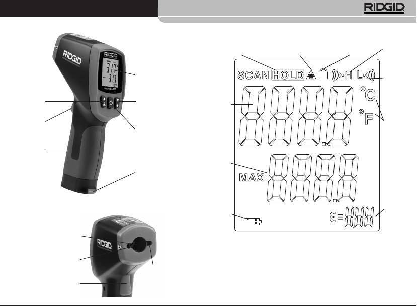
micro IR-100 Kontaktloses Infrarotthermometer
Teile Symbole LCD-Display
Alarm bei
hohen
Datenspeicherung
Laser aktivieren Verriegeln
Tempera-
turen
Alarm bei
LCD-Display
niedrigen
Tempera-
turen
Abwärtstaste/
Aufwärtstaste/
Aktueller
Hintergrund-
Laser aktivieren
Tempera-
beleuchtung
turwert
Tempera tu-
rein heiten
Auslöser
Celsius/
Menütaste
Fahrenheit
Handgriff
Maximal
tempera-
tur wert
Batteriefach
Abbildung 2 – Teile des micro IR-100
Emissions-
Batterie
grad
schwach
Infrarotsensor
Abbildung 3 – Display-Symbole des micro IR-100
Laser
Standardausstattung
Laser
• microIR-100
• Batterie1x9V
Auslöser
• Transportkoffer
• Bedienungsanleitung
Ridge Tool Company
49
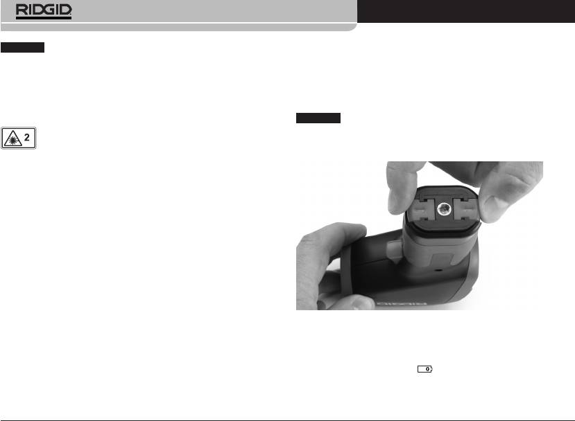
micro IR-100 Kontaktloses Infrarotthermometer
HINWEIS
Dieses Gerät dient zur Durchführung von Tem pe ra tur-
Elektromagnetische Verträglichkeit (EMV)
mes sungen. Unkorrekte oder unsachgemäße Verwendung kann zu
Der Begriff elektromagnetische Verträglichkeit bezeichnet die Fähig-
falschen oder ungenauen Messungen führen. Für die Auswahl der
keit des Produkts, in einer Umgebung, in der elektromagnetische
geeigneten Messmethoden für die jeweiligen Bedingungen ist der
Strahlung und elektrostatische Entladungen auftreten, einwandfrei
Benutzer verantwortlich.
zu funktionieren, ohne elektromagnetische Störungen anderer Geräte
zu verursachen.
Laser-Klassifizierung
HINWEIS
Das RIDGID micro IR-100 entspricht allen geltenden ECV-
Normen. Die Möglichkeit, dass er Störungen anderer Geräte verur-
Das RIDGID micro IR-100 erzeugt einen sichtbaren
sacht, kann jedoch nicht ausgeschlossen werden.
Laserstrahl, der vorne aus dem Gerät ausgesandt wird.
Das Gerät entspricht Klasse-2-Lasern gemäß: EN 60825-1:1994/
A11:1996/A2:2001/A1:2002
FCC-Erklärung
Dieses Gerät wurde getestet und erfüllt die Grenzwerte für digitale
Geräte, Klasse B, nach Teil 15 der FCC-Vorschriften. Diese Grenzwerte
sind so festgelegt, dass sie einen ausreichenden Schutz gegen
schädliche Störeinflüsse in Wohngebäuden gewährleisten.
Dieses Gerät erzeugt und nutzt Funkstrahlung und kann diese ab-
strahlen; es kann daher bei unsachgemäßer Montage und Nutzung
Funkverbindungen stören.
Es gibt jedoch keine Garantie, dass in einer bestimmten Anlage kei-
ne Störstrahlung entsteht.
Sollte dieses Gerät den Rundfunk- oder Fernsehempfang stören,
Abbildung 4 – Entfernen des Batteriefachs
was einfach durch Aus- und Einschalten des Geräts feststellbar ist, so
sollte der Benutzer eine oder mehrere der folgenden Maßnahmen
Wechseln/Einlegen der Batterien
ergreifen, um diese Störstrahlung auszuschalten:
Das micro IR-100 wird ohne eingelegte Batterien geliefert. Wenn die
• AntenneneuausrichtenoderaneineranderenStelleanbringen.
Batterieanzeige (Abbildung 3)
anzeigt, muss die Batterie gewech-
• AbstandzwischenGerätundEmpfängervergrößern.
selt werden. Entfernen Sie die Batterie vor längerer Lagerung, um ein
Auslaufen der Batterie zu verhindern.
• RücksprachemitdemHändlerodereinemRadio-/TV-Fachmann
nehmen.
50
Ridge Tool Company
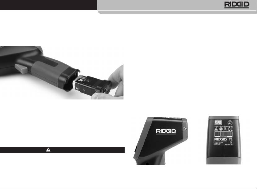
micro IR-100 Kontaktloses Infrarotthermometer
1. Drücken Sie die Batterieclips zusammen und entfernen Sie das
1. Entfernen Sie Öl, Fett oder Schmutz vom Gerät. Hierdurch wird die
Batteriefach aus dem Thermometer (Abbildung 4). Entfernen Sie
Inspektion erleichtert.
bei Bedarf die Batterie.
2. Untersuchen Sie das micro IR-100 auf beschädigte, abgenutzte,
2. Setzen Sie eine 9V Alkaline-Batterie (6LR61) unter Beachtung der
fehlende, falsch angebrachte oder klemmende Teile oder auf jegli-
korrekten Polarität, wie auf dem Batteriefach angegeben, ein.
che andere Bedingungen, die einen sicheren und normalen Betrieb
des Geräts beeinträchtigen könnten.
3. Kontrollieren Sie, ob das Schild mit den Warnhinweisen vorhanden,
sicher befestigt und gut lesbar ist (Abbildung 6).
4. Falls bei der Inspektion Mängel gefunden werden, darf das
Infrarotthermometer erst verwendet werden, wenn diese vollstän-
dig beseitigt wurden.
5. Schalten Sie entsprechend der Bedienungsanleitung das Infra-
rot thermometer ein, nehmen Sie eine Messung vor und bestä-
tigen Sie dieselbe Messung mit einem anderen Instrument
(Kontaktthermometer, usw.). Wenn die Differenz zwischen
den Messungen nicht akzeptabel ist, benutzen Sie das Infra-
Abbildung 5 – Batteriehalter und Polaritätsmarkierung
rotthermometer erst wieder, nachdem es ordnungsgemäß gewar-
tet wurde.
3. Drücken Sie die Clips zusammen und schieben Sie den Halter fest
in das Thermometer. Der Halter lässt sich nur in einer bestimmten
Richtung hineinschieben. Keine Gewalt anwenden. Vergewissern
Sie sich, dass er fest verschlossen ist.
Kontrolle vor dem Betrieb
WARNUNG
Überprüfen Sie Ihr Infrarotthermometer vor jeder Benutzung und
beheben Sie etwaige Probleme, um die Gefahr von Verletzungen
oder Fehlmessungen zu reduzieren.
Abbildung 6 – Warnaufkleber
Blicken Sie nicht in den Laserstrahl. In den Laserstrahl zu blicken,
kann die Augen schädigen.
Ridge Tool Company
51
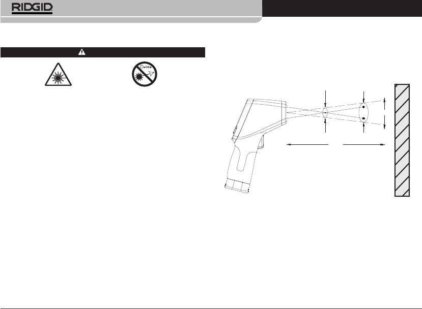
micro IR-100 Kontaktloses Infrarotthermometer
Vorbereitung und Betrieb
ben den ungefähren Durchmesser des Bereichs (“Spot”) an, in dem die
Temperatur gemessen wird. Wenn das micro IR-100 weiter (D) von der
Oberfläche entfernt wird, vergrößern sich dieser Bereich und die Spot-
WARNUNG
Größe (S). Der Bereich ist etwa 0,05-mal der Distanz zur Oberfläche
(Abbildung 7).
Blicken Sie nicht in den Laserstrahl. In den Laserstrahl zu blicken, kann die
Augen schädigen. Blicken Sie nicht mit optischen Hilfsmitteln (Fernglas
oder Fernrohr) auf den Laserstrahl.
Richten Sie den Laserstrahl nicht auf andere Personen. Vergewissern Sie
sich, dass der Laser auf einen Punkt über oder unter Augenhöhe gerich-
tet wird. Leser strahlen können schädlich für die Augen sein.
Treffen Sie bei der Arbeit in der Nähe von elektrischen, bewegenden oder
heißen Teilen entsprechende Vorsichtsmaßnahmen. Enger Kontakt kam
zum Stromschlägen, Verfangen, Verbrennungen und anderen schweren
Verletzungen führen. Eventuell ist Schutzausrüstung erforderlich.
Befolgen Sie bei Vorbereitung und Benutzung des Infrarot Thermometers
diese Verfahren, um die Gefahr von Verletzungen oder unkorrekten
Messungen zu mindern.
Setup
1. Überprüfen Sie, ob der Arbeitsbereich, wie im Abschnitt Allgemeine
Sicherheit beschrieben, für das Gerät geeignet ist.
Der Spot sollte immer kleiner sein als die Oberflächen. Je kleiner die
Oberfläche, desto näher sollte sich das micro IR-100 an der Oberfläche
2. Überprüfen Sie das zu messende Objekt und vergewissern Sie sich,
befinden. Optimale Genauigkeit wird erzielt, wenn die Oberfläche
dass Sie das richtige Gerät für die Anwendung haben. Reichweite,
doppelt so groß ist wie der Spot.
Genauigkeit und andere Informationen siehe Abschnitt Technische
Daten.
Emissionsgrad – Der Begriff Emissionsgrad beschreibt die Energie-
emissionseigenschaften von Materialien und hat einen Wert zwi-
Zahlreiche Faktoren können die Genauigkeit des micro IR-100 beein-
schen 0 und 1. Das micro IR-100 arbeitet mit einem festgelegten
flussen, darunter:
Emissionsgrad von 0,95, um Temperaturen zu berechnen. Dieser Wert
Sichtfeld – Das micro IR-100 arbeitet mit zwei Lasern, die Punkte auf
ist für die meisten Verwendungsmöglichkeiten, einschließlich der mei-
beide Seiten des zu messenden Bereichs projizieren. Diese Punkte ge-
sten lackierten Oberflächen, angemessen.
52
Ridge Tool Company
D:S=20:1
25.4mm @
508mm
508mm @
1016mm
S
1.0in@ 20in
2.0in@ 40in
D
Oberfläche
Abbildung 7 – Sichtfeld

micro IR-100 Kontaktloses Infrarotthermometer
Glänzende oder polierte Oberflächen haben einen niedrigen
2. Betätigen Sie den Auslöser, um das micro IR-100 einzuschalten. Wenn
Emissionsgrad und ergeben ungenaue Messungen. Eine Möglich-
der Auslöser betätigt wird, wird das SCAN-Symbol angezeigt und das
keit, dies zu kompensieren besteht darin, die Oberfläche mit
micro IR-100 aktualisiert laufend die angezeigte Temperatur und zeigt
Maskierklebeband abzukleben oder schwarze Farbe darauf aufzutra-
die Maximaltemperatur seit Einschalten des Geräts.
gen. Warten Sie, bis das Klebeband oder die Farbe dieselbe Temperatur
Das micro IR-100 kann langsam über die Oberfläche bewegt werden,
wie die Oberfläche erreicht haben und messen Sie die Temperatur des
um heiße oder kalte Bereiche zu lokalisieren. Informationen über die
Klebebands oder der Farbe.
Einstellung des Alarms für zu hohe und zu niedrige Temperaturen sie-
Temperatur – Das micro IR-100 kompensiert zwar Schwankungen
he Abschnitte über Alarm bei zu niedriger und zu hoher Temperatur.
der Umgebungstemperatur, erhebliche Veränderungen der Umge-
3. Wenn der Auslöser losgelassen wird, erscheint das Symbol HOLD. Das
bungs- und der gemessenen Temperaturen können aber die
micro IR-100 schaltet sich nach sieben Sekunden automatisch ab, es
Genauigkeit beeinträchtigen. Wenn erhebliche Veränderungen der
sei denn es befindet sich im Dauermessmodus.
Umgebungstemperatur (mehr als 17°C oder 30°F) auftreten, warten
Sie 15 Minuten, bis das micro IR-100 sich angepasst hat, um eine mög-
lichst hohe Genauigkeit zu erreichen.
micro IR-100 Bedienelemente
Hindernisse – Dampf, Staub, Rauch und andere Hemmnisse wie Glas
oder Kunststoff zwischen dem micro IR-100 und der gemessenen
Oberfläche können die Genauigkeit beeinträchtigen. Sie behindern die
Optik des Geräts oder führen zu Fehlmessungen (die Temperatur des
Glases anstatt die der Oberfläche wird gemessen). Wenn Hindernisse
LCD-Display
vorhanden sind, nicht benutzen.
Berücksichtigen Sie diese Faktoren vor Benutzung des micro IR-100.
3. Stellen Sie sicher, dass alle Geräte ordnungsgemäß kontrolliert wur-
den.
Betrieb
Abwärtstaste/
Auslöser
Hintergrund-
Ein- und Ausschalten (Messungen durchführen)
beleuchtung
1. Halten Sie das micro IR-100 am Griff fest und richten Sie es auf die zu
messende Oberfläche. Halten Sie sich von elektrischen, bewegenden
Laser
Menütaste
oder heißen Teilen fern. Vergewissern Sie sich vor dem Einschalten,
dass der Laser in eine sichere Richtung, weg von in der Nähe befindli-
chen Personen, weist.
Abbildung 8 – Display/Tasten des micro IR-100
Ridge Tool Company
53

micro IR-100 Kontaktloses Infrarotthermometer
Dauermessmodus (Scannen)
Alarm bei hohen Temperaturen
Das micro IR-100 kann im eingeschalteten Zustand verriegelt werden, um
Der Alarm bei hohen Temperaturen erfolgt in Form eines akustischen
Messungen ohne Festhalten des Auslöser zu ermöglichen. Vergewissern
Signals, wenn die aktuelle Temperatur einen voreingestellten Grenzwert
Sie sich vor dem Einschalten, dass der Laser in eine sichere Richtung, weg
überschreitet. Zum Einschalten des Alarms bei hohen Temperaturen betä-
von in der Nähe befindlichen Personen, weist. Schalten Sie das micro
tigen Sie den Auslöser und lassen ihn wieder los, anschließend drücken Sie
IR-100 ein, indem Sie den Auslöser betätigen und festhalten. Halten Sie den
die Menütaste, bis das Symbol für hohen Alarm blinkt und lassen sie wie-
Auslöser gedrückt, dabei die Menütaste drücken und loslassen. Das SCAN-
der los. Schalten Sie mit der Aufwärts-/Abwärtstaste den Alarm bei hohen
und das Verriegelungssymbol erscheinen. Lassen Sie den Auslöser los, das
Temperaturen ein/aus, wie in der Zeile für den aktuellen Temperaturwert
micro IR-100 aktualisiert nun laufend die gemessene Temperatur, bis der
angezeigt. Die Menütaste erneut drücken und wieder loslassen. Das Symbol
Auslöser erneut gedrückt und wieder losgelassen wird.
für hohen Alarm blinkt weiter und die Temperatur für Auslösung des ho-
hen Alarms wird angezeigt. Ändern Sie mit der Aufwärts-/Abwärtstaste
Laser aktiviert/deaktiviert
die Temperatur für Auslösung des hohen Alarms nach Bedarf. Betätigen
Bei Bedarf können die zum Anvisieren verwendeten Laser abgeschal-
Sie den Auslöser, um den Einstellmodus zu beenden und Ihre Auswahl zu
tet werden, um die Batterie zu schonen. Wenn dies geschieht, muss mit
speichern.
dem micro IR-100 besonders sorgfältig anvisiert werden, um genaue
Messungen zu gewährleisten. Zum Aktivieren oder Deaktivieren drücken
Alarm bei niedrigen Temperaturen
Sie, während Sie den Auslöser festhalten, die Laseraktivierungstaste und
Der Alarm bei niedrigem Temperaturen erfolgt in Form eines akusti-
lassen Sie sie wieder los. Das Laseraktivierungssymbol ist sichtbar, wenn
schen Signals, wenn die aktuelle Temperatur unter einen voreingestellten
der Laser aktiviert ist.
Grenzwert sinkt. Zum Einschalten des Alarms bei niedrigen Temperaturen
betätigen Sie den Auslöser und lassen ihn wieder los, anschließend drük-
Hintergrundbeleuchtung
ken Sie die Menütaste, bis das Symbol für niedrigen Alarm blinkt und las-
Für den Einsatz unter schlechten Beleuchtungsverhältnissen ist das micro
sen sie wieder los. Schalten Sie mit der Aufwärts-/Abwärtstaste den Alarm
IR-100 mit einer Display-Hintergrundbeleuchtung ausgestattet. Zum Ein-
bei niedrigen Temperaturen ein/aus, wie in der Zeile für den aktuellen
und Ausschalten der Hintergrundbeleuchtung drücken Sie bei eingeschal-
Temperaturwert angezeigt. Die Menütaste erneut drücken und wieder los-
tetem Gerät die Hintergrundbeleuchtungstaste.
lassen. Das Symbol für niedrigen Alarm blinkt weiter und die Temperatur
für Auslösung des niedrigen Alarms wird angezeigt. Ändern Sie mit der
Benutzung der Menütaste
Aufwärts-/Abwärtstaste die Temperatur für Auslösung des niedrigen
Alarms nach Bedarf. Betätigen Sie den Auslöser, um den Einstellmodus zu
Nach Betätigung des Auslösers können Sie durch Drücken und Loslassen
beenden und Ihre Auswahl zu speichern.
der Menütaste die folgenden Einstellungen in dieser Reihenfolge durch-
gehen: Alarm bei hoher Temperatur ein/aus, Einstellung der Temperatur
Temperaturanzeigeeinheiten - °C/°F
für hohen Alarm, Alarm bei niedriger Temperatur ein/aus, Einstellung der
Temperatur für niedrigem Alarm, Temperatureinheiten.
Das micro IR-100 kann Temperaturen in Grad Celsius (C) oder Fahrenheit
(F) anzeigen. Zum Ändern der Anzeigeeinheit den Auslöser betätigen
und wieder loslassen, dann die Menütaste drücken und loslassen, bis die
54
Ridge Tool Company

micro IR-100 Kontaktloses Infrarotthermometer
Temperatureinheit auf dem Display blinkt. Mit der Aufwärts-/Abwärtstaste
Falls Sie Informationen zu einem RIDGID Kundendienst-Center in Ihrer
nach Bedarf zwischen C oder F wechseln. Betätigen Sie den Auslöser, um
Nähe benötigen oder Fragen zu Service oder Reparatur haben:
den Einstellmodus zu beenden und Ihre Auswahl zu speichern.
• WendenSiesichanIhrenörtlichenRIDGIDHändler.
• Unterwww.RIDGID.comoderwww.RIDGID.eufindenSieIhreörtliche
Reinigung
RIDGID Kontaktstelle.
Das RIDGID micro IR-100 kontaktlose Infrarotthermometer nicht in Was-
• WendenSiesichandieAbteilungTechnischerKundendienstvonRIDGID
ser tauchen. Wischen Sie Schmutz mit einem feuchten weichen Tuch
unter rtctechservices@emerson.com oder in den USA und Kanada tele-
ab. Verwenden Sie keine aggressiven Reinigungsmittel oder -lösungen.
fonisch unter (800) 519-3456.
Behandeln Sie das Instrument mit der gleichen Sorgfalt wie ein Teleskop
oder eine Kamera.
Entsorgung
Teile des RIDGID micro IR-100 kontaktlosen Infrarotthermometers ent-
Aufbewahrung
halten wertvolle Materialien, die recycelt werden können. Hierfür gibt
Das RIDGID micro IR-100 kontaktlose Infrarotthermometer muss in einem
es auf Recycling spezialisierte Betriebe, die u. U. auch örtlich ansäs-
trockenen sicheren Bereich bei einer Temperatur zwischen -10°C (14°F) und
sig sind. Entsorgen Sie die Teile entsprechend den örtlich geltenden
60°C (158°F) gelagert werden.
Bestimmungen. Weitere Informationen erhalten Sie bei der örtlichen
Lagern Sie das Gerät in einem abgeschlossenen Bereich außer Reichweite
Abfallwirtschaftsbehörde.
von Kindern und Personen, die mit dem micro IR-100 nicht vertraut sind.
Für EGLänder: Werfen Sie Elektrogeräte nicht in den
Entfernen Sie vor längeren Lagerperioden oder vor dem Versand die
Hausmüll!
Batterien, um ein Auslaufen der Batterie zu vermeiden.
Gemäß der Europäischen Richtlinie 2002/96/EG über
Elek tro- und Elektronik-Altgeräte und ihrer Umsetzung
Wartung und Reparatur
in nationales Recht müssen nicht mehr gebrauchsfähige
Elektrogeräte getrennt gesammelt und einer umweltgerechten Wie-
derverwertung zugeführt werden.
WARNUNG
Die Betriebssicherheit des RIDGID micro IR-100 kontaktlosen Infrarot-
Entsorgung von Akkus
thermometers kann durch unsachgemäße Wartung oder Reparatur be-
einträchtigt werden.
Für EU-Länder: Gemäß der Richtlinie 2006/66/EWG müssen defekte oder
verbrauchte Batterien recycelt werden.
Wartungs- und Reparaturarbeiten am micro IR-100 dürfen nur von einem
von RIDGID autorisierten Kundendienst-Center durchgeführt werden.
Ridge Tool Company
55

micro IR-100 Kontaktloses Infrarotthermometer
56
Ridge Tool Company


