Ridgid micro DL-500: instruction
Class: Tools, power tools and power equipment
Type:
Manual for Ridgid micro DL-500
micro
DL-500
EN
p. 1
FR
p. 13
ES
p. 25
DE
p. 37
NL
p. 49
IT
p. 61
PT
p. 73
SV
p. 85
DA
p. 97
NO
p. 109
FI
p. 121
PL
p. 133
CZ
p. 145
SK
p. 157
RO
p. 169
HU
p. 181
EL
p. 193
HR
p. 205
SL
p. 217
SR
p. 229
RU
p. 241
TR
p. 253
RIDGE TOOL COMPANY
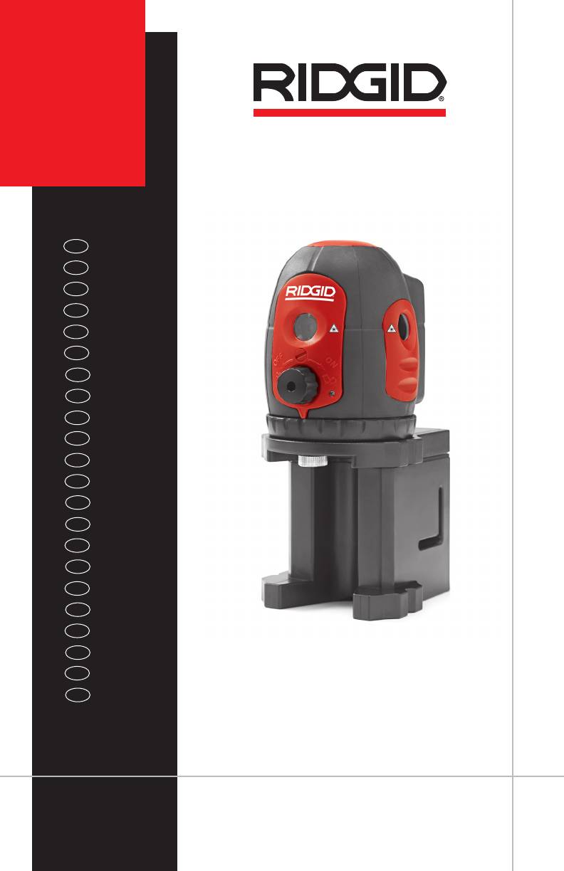
micro DL-500
micro DL-500
Self-Leveling 5-Dot Laser
WARNING!
Read this Operator’s Manual
carefully before using this
tool. Failure to understand
and follow the contents of
this manual may result in
micro DL-500 Self-Leveling 5-Dot Laser
electrical shock, re and/or
Record Serial Number below and retain product serial number which is located on nameplate.
serious personal injury.
Serial
No.

micro DL-500 Self-Leveling 5-Dot Laser
Contents
Safety Symbols .................................................................................................................................................3
General Safety Information.......................................................................................................................3
Work Area Safety ...........................................................................................................................................3
Electrical Safety .............................................................................................................................................3
Personal Safety ..............................................................................................................................................3
Equipment Use and Care ........................................................................................................................... 4
Service ............................................................................................................................................................... 4
Specic Safety Information ....................................................................................................................... 4
Self-Leveling 5-Dot Laser Safety ............................................................................................................. 4
Description, Specications and Standard Equipment ...............................................................5
Description ......................................................................................................................................................5
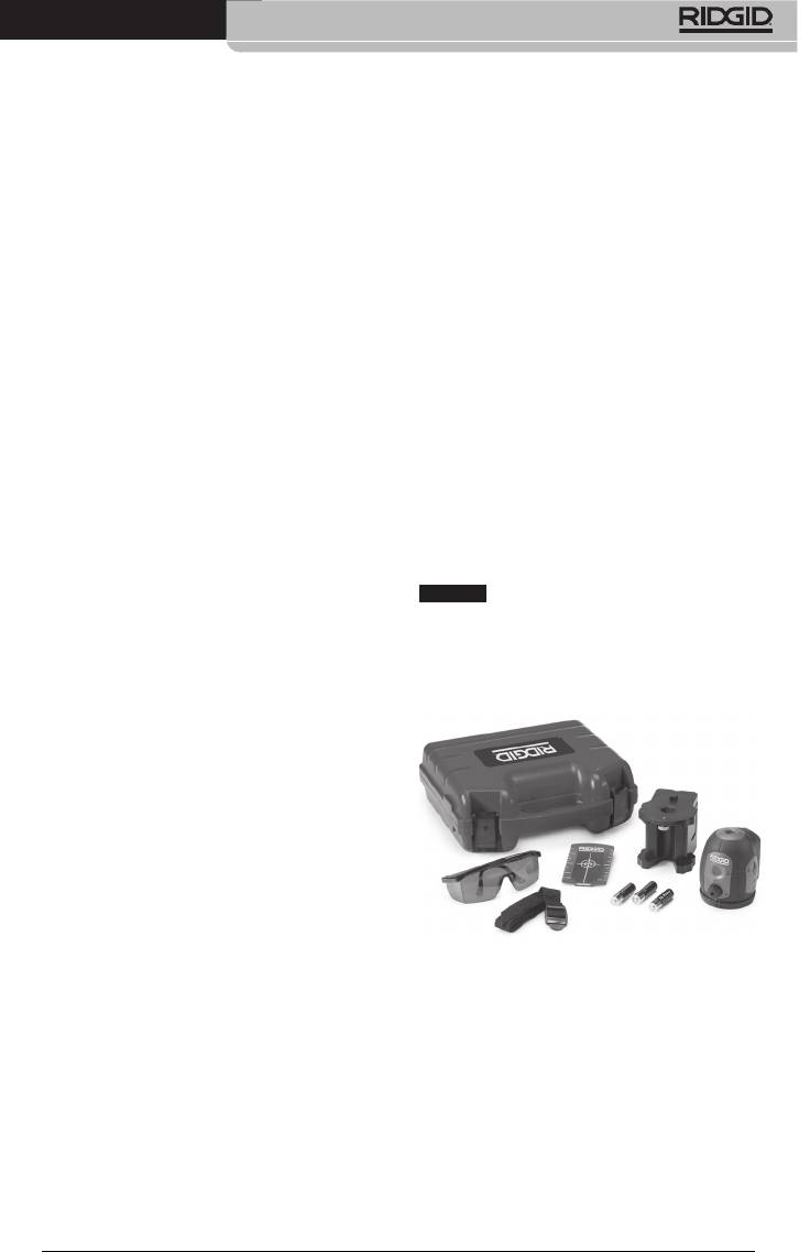
Standard Equipment ................................................................................................................................... 5
Specications ................................................................................................................................................. 5
Icons .......................................................................................................................................................................6
Laser Classication ........................................................................................................................................ 6
Electromagnetic Compatibility (EMC) .................................................................................................6
Changing/Installing Batteries ..................................................................................................................6
Pre-Operation Inspection ..........................................................................................................................7
Set-Up and Operation ..................................................................................................................................7
Level Checks ...................................................................................................................................................... 8
Up Beam Check ............................................................................................................................................. 8
Checking the Horizontal Beams ............................................................................................................ 9
Cleaning Instructions ...................................................................................................................................9
Accessories .........................................................................................................................................................9
Storage and Transportation ....................................................................................................................10
Service and Repair........................................................................................................................................10
Disposal .............................................................................................................................................................10
Battery Disposal ............................................................................................................................................10
Troubleshooting ............................................................................................................................................11
Lifetime Warranty .......................................................................................................................Back Cover
*Original Instructions - English
2
micro DL-500 Self-Leveling 5-Dot Laser
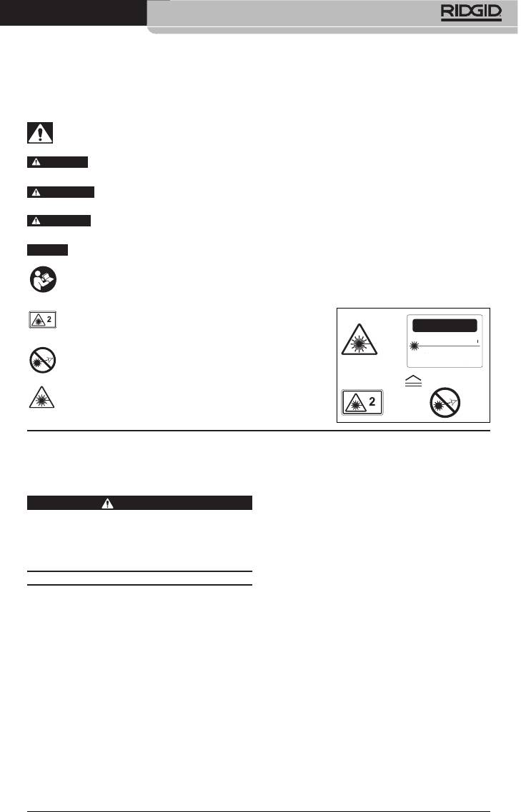
Safety Symbols
In this operator’s manual and on the product, safety symbols and signal words are used to
communicate important safety information. This section is provided to improve understand-
ing of these signal words and symbols.
This is the safety alert symbol. It is used to alert you to potential personal injury hazards.
Obey all safety messages that follow this symbol to avoid possible injury or death.
DANGER
DANGER indicates a hazardous situation which, if not avoided, will result in death
or serious injury.
WARNING
WARNING indicates a hazardous situation which, if not avoided, could result in
death or serious injury.
CAUTION
CAUTION indicates a hazardous situation which, if not avoided, could result in mi-
nor or moderate injury.
NO TICE
NOTICE indicates information that relates to the protection of property.
This symbol means read the operator’s manual carefully before using the equipment.
The operator’s manual contains important information on the safe and proper operation
of the equipment.
This symbol means this device contains a Class 2 La-
ser.
This symbol means do not stare into the laser beam.
This symbol warns of the presence and hazard of a
laser beam.
Electrical Safety
General Safety
Avoid body contact with earthed or
Information
grounded surfaces such as pipes, radi-
ators, ranges and refrigerators. There
WARNING
is an increased risk of electrical shock if
Read all safety warnings and instructions.
your body is earthed or grounded.
Failure to follow the warnings and instruc‑
tions may result in electric shock, fire and/
Do not expose equipment to rain or
or serious injury.
wet conditions. Water entering equip-
ment will increase the risk of electrical
SAVE THESE INSTRUCTIONS!
shock.
Personal Safety
Work Area Safety
Stay alert, watch what you are do-
Keep your work area clean and well
ing and use common sense when
lit. Cluttered or dark areas invite acci-
operating equipment. Do not use a
dents.
tool while you are tired or under the
Do not operate equipment in explosive
inuence of drugs, alcohol or medi-
atmospheres, such as in the presence
cation. A moment of inattention while
of ammable liquids, gases or dust.
operating equipment may result in se-
Equipment can create sparks which may
rious personal injury.
ignite the dust or fumes.
Do not overreach. Keep proper foot-
Keep children and by-standers away
ing and balance at all times. This en-
while operating equipment. Distrac-
ables better control of the the equip-
tions can cause you to lose control.
ment in unexpected situations.
3
CAUTION
LASER RADIATION
DO NOT STARE INTO BEAM
MAXIMUM OUTPUT < 1mW
WAVELENGTH 630-670nm
CLASS 2 LASER PRODUCT
EN 60825-1:1994/A11:1996/A2:2001/A1:2002

micro DL-500 Self-Leveling 5-Dot Laser
Use personal protective equipment.
Specific Safety
Always wear eye protection. Protective
equipment such as dust mask, non-
Information
skid safety shoes, hard hat or hearing
protection used for appropriate condi-
WARNING
tions will reduce personal injuries.
This section contains important safety in‑
formation that is specific to the equipment.
Equipment Use and Care
Read these precautions carefully before us‑
Do not force equipment. Use the cor-
ing the RIDGID® micro DL‑500 Self‑Leveling
rect equipment for your application.
5‑Dot Laser to reduce the risk of eye injury
The correct equipment will do the job
or other serious injury.
better and safer at the rate for which it
is designed.
SAVE THESE INSTRUCTIONS!
Do not use equipment if the switch
Keep this manual with the equipment for use
does not turn it ON and OFF. Any tool
by the operator.
that cannot be controlled with the
switch is dangerous and must be re-
Self‑Leveling 5‑Dot Laser Safety
paired.
Do not look into the laser beam.
Disconnect the batteries from the
Looking into the laser beam may be
equipment before making any ad-
hazardous to the eyes. Do not look at
justments, changing accessories, or
the laser beam with optical aids (such
storing. Such preventive safety mea-
as binoculars or telescopes).
sures reduce the risk of injury.
Store idle equipment out of the reach
other people. Make sure the laser is
of children and do not allow per-
aimed above or below eye level. Laser
sons unfamiliar with the equipment
beams may be hazardous to the eyes.
or these instructions to operate the
equipment. Equipment can be danger-
as safety goggles. The laser viewing
ous in the hands of untrained users.
glasses are designed to enhance the
Maintain equipment. Check for break-
visibility of the laser, but they do not
age of parts and any other condition
protect against laser radiation.
that may aect the equipment’s opera-
tion. If damaged, have the equipment
aimed at a surface without reective
repaired before use. Many accidents
properties. Shiny surfaces may cause
are caused by poorly maintained
the laser beam to be reected back at
equipment.
the user or others and may be injurious
Use the equipment and accessories in
to the eyes.
accordance with these instructions,
taking into account the working con-
in use and after each use. Turn it OFF
ditions and the work to be performed.
when it is not used even for a short pe-
Use of the equipment for operations
riod or when the operator leaves the
dierent from those intended could
instrument. Leaving the equipment
result in a hazardous situation.
ON increases the risk of someone inad-
Use only accessories that are recom-
vertently staring into the laser beam.
mended by the manufacturer for your
The EC Declaration of conformity (890-011-
equipment. Accessories that may be
320.10) will accompany this manual as a
suitable for one piece of equipment may
separate booklet when required.
become hazardous when used with oth-
er equipment.
If you have any question concerning this
RIDGID® product:
Service
– Contact your local RIDGID distributor.
Have your equipment serviced by a
– Visit www.RIDGID.com or www.RIDGID.eu
qualied repair person using only
to nd your local RIDGID contact point.
identical replacement parts. This will
ensure that the safety of the tool is main-
tained.
4
micro DL-500 Self-Leveling 5-Dot Laser
– Contact RIDGID Technical Services De part-
Protection
ment at rtctechservices@emer son.com, or
Rating............................
IP 55
in the U.S. and Canada call (800) 519-3456.
Dimension................... 3.15" × 3.86" × 4"
(80 mm × 98 mm ×
Description, Specifications
101 mm)
and Standard Equipment
Weight.......................... 1.1 lbs (0,5 kg)
Description
Mounting Screw
1
5
Thread.........................
/
4
" - 20 &
/
8
" - 11
The RIDGID micro DL-500 Self-Leveling 5-Dot
Laser is a professional laser. The laser simulta-
Standard Equipment
neously projects ve laser beams (up, down,
front, left and right directions) for plumb and
The RIDGID micro DL-500 Self-Leveling
level applications. It is primarily for use in-
5-Dot Laser includes the following items:
doors, but may be used outside depending
on light conditions.
The self-leveling laser has a multi-functional
magnetic base for attaching to a tripod or
steel surfaces. The laser itself can swivel 360
degrees.
The laser self-levels within a range of ±4.5°.
The laser beam will ash and an intermittent
beep will sound if the laser is outside of its
leveling range. The laser features a magnetic
dampened compensation system to main-
NO TICE
This equipment is used to dene
tain level even when aected by vibration on
plumb and level references. Incorrect use
the job site.
or improper application may result in non-
The laser has a locking mechanism built into
plumb or level references. Selection of ap-
the ON/OFF switch to hold the internal com-
propriate methods for the conditions is the
ponents in place to avoid damage during
responsibility of the user.
transport and storage. The laser is powered
by three AA Alkaline batteries and has a low
battery indicator.
Specifications
Interior Range............ Up to 100 ft (30 m)
depending upon Light
Conditions
1
Accuracy....................... ±
/
8
" / 50 ft
(± 2 mm / 10 m)
Self-Leveling
Range..........................
± 4.5°
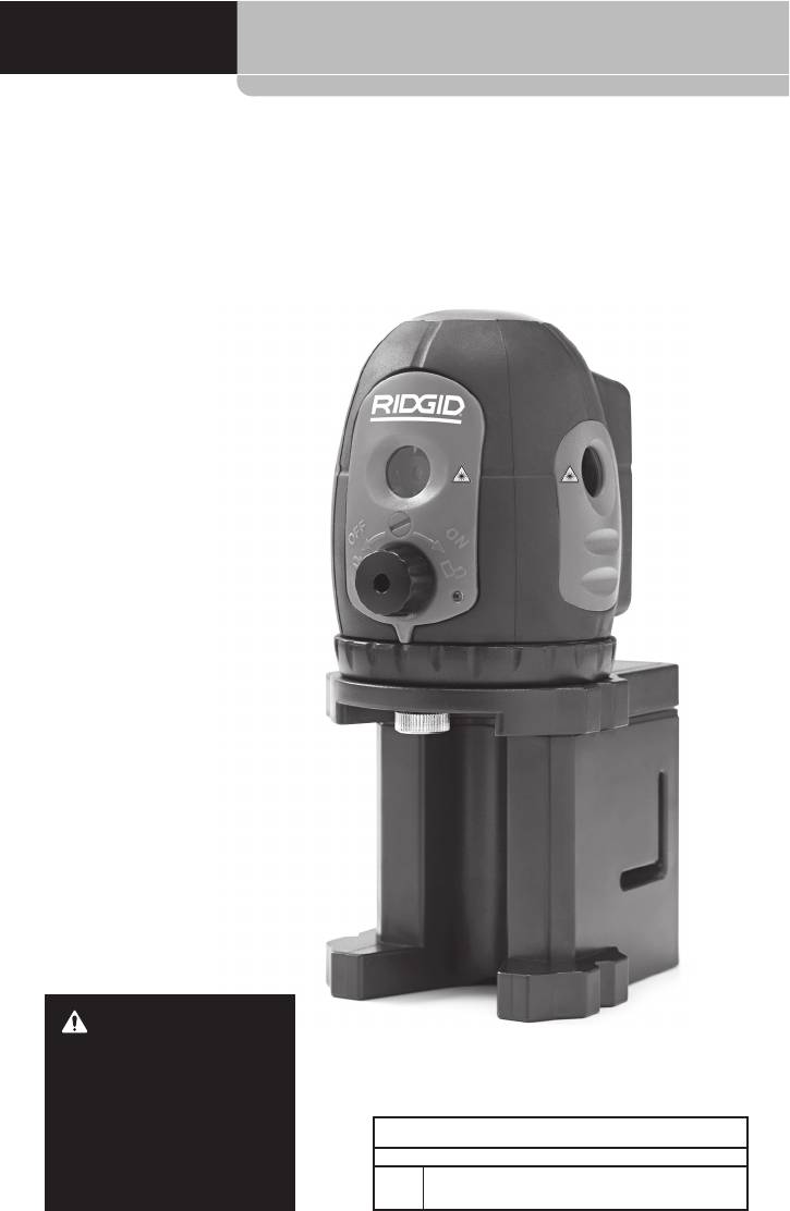
Figure 1 - RIDGID micro DL-500 Self-Level-
Laser
ing 5-Dot Laser
Classication..............
Class 2
Laser
Wavelength................
630 nm – 670 nm
Maximum Power
Output..........................
≤1 mW
Power Supply............. 3 × AA Alkaline
Batteries
Operating
Temperature...............
14°F to 113°F
(-10°C to 45°C)
5
micro DL-500 Self-Leveling 5-Dot Laser
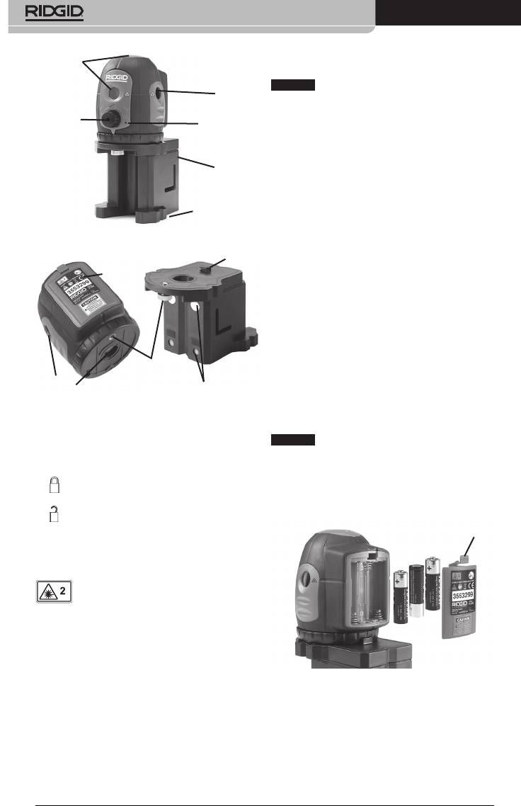
Laser
causing electromagnet interference to other
Windows
equipment.
NO TICE
The RIDGID micro DL-500 Self-Leveling
Laser
Window
5-Dot Laser conforms to all applicable EMC stan-
dards. However, the possibility of them causing
ON/OFF
Power Indicator
Switch
Light
interference in other devices cannot be preclud-
ed.
Magnetic
Base
Changing/Installing
Batteries
5
/
8
- 11 Thread
The RIDGID micro DL-500 Self-Leveling 5-Dot
for Mounting
(Underside)
Laser is supplied without batteries installed.
When the laser is ON, if the Power Indicator
Figure 2 - Laser Parts
Light blinks, the batteries need to be re-
Position
placed. Remove the batteries prior to long
tab
Battery
term storage to avoid battery leakage
Door
1. Make sure the laser is OFF (ON/OFF
switch turned fully counter clockwise).
2. Remove the battery cover by depressing
the tab (Figure 4). If present, remove the
white sensormatic tag from the battery
compartment. Remove the batteries if
1
/
4
- 20 Thread
needed.
for Mounting
Rare Earth
Laser
Magnets
3. Install three AA (LR6) batteries into bat-
Window
tery holder, observing the correct polar-
Figure 3 - Laser Level Parts
ity as indicated in the battery compart-
ment.
NO TICE
Use batteries that are of the same
Icons
type. Do not mix battery types. Do not mix
new and used batteries. Mixing batteries can
cause overheating and battery damage.
LOCK
4. Securely replace the battery cover.
UNLOCK
Tab
Laser Classification
The RIDGID micro DL-500 Self- Leveling
5-Dot Laser generates visible laser
beams that are emitted from the top, bottom,
front and sides of the device.
The device complies with class 2 lasers accord-
ing to: EN 60825-1:1994/A11:1996/- A2:2001/
A1:2002
Figure 4 - Battery Installation
Electromagnetic
Compatibility (EMC)
The term electromagnetic compatibility is
taken to mean the capability of the prod-
uct to function smoothly in an environment
where electromagnetic radiation and elec-
trostatic discharges are present and without
6
micro DL-500 Self-Leveling 5-Dot Laser
Pre‑Operation Inspection
Set‑Up and Operation
WARNING
WARNING
Before each use, inspect your laser level
and correct any problems to reduce the risk
of injury and prevent tool damage.
Do not look into the laser beam. Looking
into the laser beam may be hazardous to
the eyes.
Do not look into the laser beam. Looking
1. Make sure the unit is OFF and the sel-
into the laser beam may be hazardous to
eveling mechanism locked (ON/OFF
the eyes. Do not look at the laser beam
switch turned fully counterclockwise).
with optical aids (such as binoculars or tele‑
scopes).
2. Remove the batteries and inspect for
signs of damage. Replace batteries if
Do not direct the laser beam towards other
necessary. Do not use equipment if the
people. Make sure the laser is aimed above
batteries are damaged.
or below eye level. Laser beams may be
hazardous to the eyes.
3. Clean any oil, grease or dirt from the
equipment. This aids inspection and
Set‑up and operate the RIDGID micro DL‑ 500
helps prevent the tool from slipping
Self‑Leveling 5‑Dot Laser and work area ac‑
from your grip.
cording to these procedures to reduce the
risk of injury eye exposure to the laser and
4. Inspect the laser for any broken, worn,
other causes, and prevent tool damage.
missing or binding parts or any condi-
tion which may prevent safe and normal
1. Check for an appropriate work area as
operation.
indicated in the General Safety section.
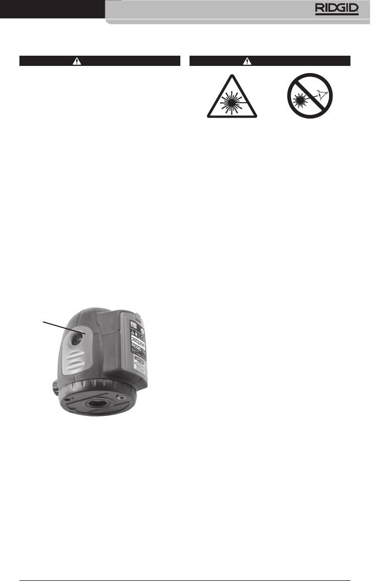
5. Check that the warning labels are pres-
2. Examine the work to be done and de-
ent, rmly attached and readable.
termine if the RIDGID micro DL-500 Self-
Leveling 5-Dot Laser is the correct piece
At Each Laser
of equipment for the job. See Specica-
Output Window
tion section for more information.
distances up to 100 feet (30 m). Use in
bright sunlight may reduce the usable
distance. The laser viewing glasses
are designed to enhance the visibility
of the laser, but they do not protect
against laser radiation. Never look into
the laser.
at surfaces without reective proper-
Figure 5 - Warning Labels
ties. Shiny surfaces may cause the laser
beam to be reected back at the user
6. If any issues are found during the inspec-
or others and may be hazardous to the
tion, do not use the laser until it has been
eyes. Wood, rough or painted surfaces
properly serviced.
are generally acceptable. In some cas-
7. With dry hands, re-install the batteries
es, applying a commercially available
making sure to fully insert.
laser target plate may help in locating
the laser on surfaces.
8. Following the Set-Up and Operation In-
structions, perform the level check. Do
-
not use the laser if it has not been prop-
standers and other distractions to help
erly checked.
prevent inadvertent eye contact with
the laser beam.
7
micro DL-500 Self-Leveling 5-Dot Laser
3. Make sure the laser has been properly
Whatever conguration the laser is used
inspected before each use.
in, it must be secure and stable to pre-
vent the unit from tipping or falling. The
4. Set up the micro DL-500 Laser for the ap-
laser must be placed within +/-4.5 de-
plication. The laser unit can be mounted
grees of level to self level when turned
directly to a tripod or other attachment
5
1
ON.
with the
/
8
" - 11 or
/
4
" - 20 thread. If us-
ing the base, align the tab on the base
5. Keep your eyes and face clear of the la-
mounting surface with the slot in the
ser output windows. Turn the ON/OFF
bottom of the laser and secure with the
switch fully clockwise. Five laser beams
1
supplied
/
4
" - 20 screw.
will be generated (i.e. left, right, front,
up, and down) and will be visible as red
The base can be placed on most rela-
points on the adjacent surfaces. This will
tively at, level surfaces. The base is also
also release the locking mechanism and
equipped with magnets to allow mount
allow the laser unit to self-level. If the
ing to steel objects in a variety of posi-
laser is more than 4.5° from level, the
tions. Additionally, the base has top and
laser beam will ash and an intermittent
bottom sections that can be rotated rela-
beep will sound. If this occurs, turn the
tive to each other. See Figure 6 for com-
laser OFF and set up closer to level. De-
mon conguration.
pending on the circumstances, the unit
should selevel within a few seconds.
1
/
4
" - 20
Screw
6. Once the laser is ON, the lasers can be
rotated to align with desired features. Do
not touch the laser unit while measure-
ments are being made – this can prevent
Magnets
the laser from being level and give a false
reading. At this point, the laser beams
Base
can be used as a reference point for mea-
Strap Slots
surements, etc.
7. Any time the laser is not being used, turn
5
the laser OFF by turning the ON/OFF
/
8
" - 11
Thread
switch counterclockwise to help prevent
inadvertent eye contact with the laser
beam.
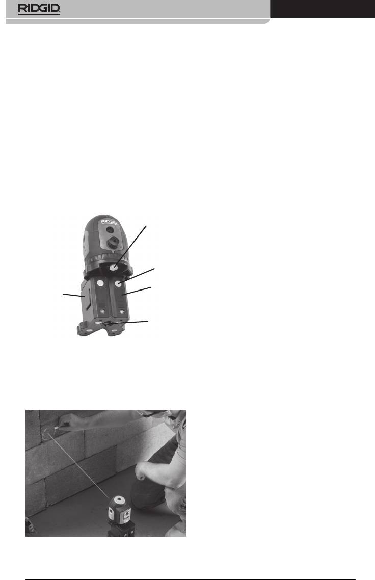
Figure 6 -Base
8. While the laser is in the upright position,
In cases where the magnets will not
lock the self-leveling mechanism prior to
hold the laser in place (such as on plastic
transportation and storage by turning
pipe), use the mounting strap in the slots
the ON/OFF switch fully counterclock-
on the base to retain the level in place.
wise. Do not move the laser if the self-
leveling mechanism is not locked as this
can damage the unit.
Level Checks
Always check the Up Beam and the Horizontal
Beams prior to use to make sure that the unit
is properly leveling and calibrated.
Up Beam Check
1. With the laser attached to its base, set on
a at surface inside a room. Turn the laser
ON.
2. Mark the location of the down beam on
the at surface. This will be the reference
Figure 7 - Using the mounting strap to hold
point.
the Laser in position
3. Locate the up beam on the ceiling or sur-
face above the laser and mark its point
as position A. Measure the distance from
8
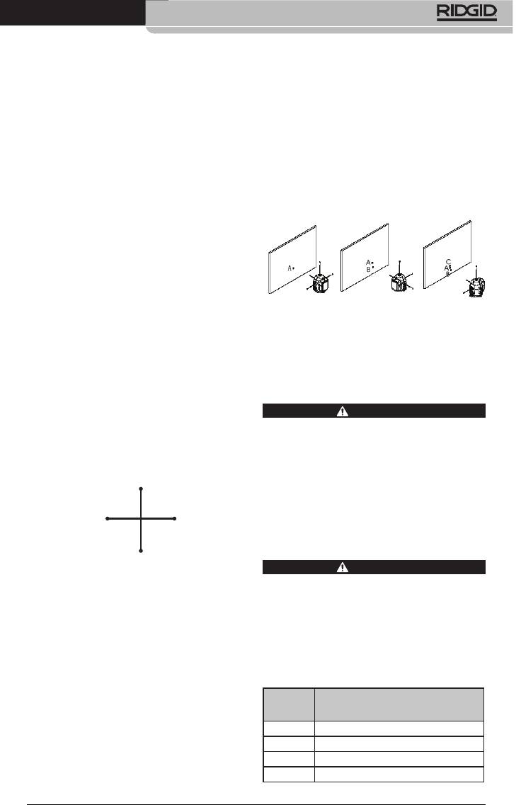
micro DL-500 Self-Leveling 5-Dot Laser
the laser to the surface that the mark is
on (this distance is L). L must be greater
than 12.5 feet (3,8 m).
4. Calculate the acceptable misalignment:
0.005
-
ters) by 0.417
5. Rotate the laser 180° clockwise by swivel-
ing the laser on its base (do not move the
base). Make sure that the down beam is
positioned on the reference point. Mark
the up beam location as position B.
6. Rotate the laser 90° clockwise by swivel-
ing the laser on its base (do not move the
base). Make sure that the down beam is
positioned on the reference point. Mark
the up beam location as position C.
7. Rotate the laser 180° clockwise by swivel-
ing the laser on its base (do not move the
base). Make sure that the down beam is
positioned on the reference point. Mark
the up beam location as position D.
8. Measure the distance between points A
and B and between points C and D. If the
distance between the points is greater
than acceptable misalignment calculat-
ed in step 4, have the laser serviced. This
cannot be eld calibrated.
9
0º (A)
90º (C)270º (D)
180º (B)
5. Rotate the laser 180° by swiveling the
laser on its base (do not move the base)
to point the right laser beam at the wall.
Mark the right beam location as position
C.
6. Points A, B and C should all fall in a ver-
tical line. Vertically there should be no
more than 0.125" (3,2 mm) between the
highest and lowest points. If the mea-
surement exceeds 0.125" (3,2 mm), have
the laser serviced. This cannot be eld
calibrated.
Figure 9 - Self-Checking the 3 Horizontal
Beams
Cleaning Instructions
WARNING
Remove the batteries before cleaning.
Keep the micro DL-500 Self-Leveling Laser
dry and clean. Do not immerse in water.
Gently wipe o with a damp soft cloth. Do
not use any detergents or solvents. Pay spe-
cial attention to the laser output windows –
remove any lint or bers.
Accessories
WARNING
Remove the batteries before cleaning.
Figure 8 - Up Beam Check
To reduce the risk of serious injury, only use
accessories specically designed and recom-
Checking the Horizontal Beams
mended for use with the RIDGID micro DL-500
1. As shown in Figure 9, squarely set up the
Self-Leveling 5-Dot Laser such as those listed
laser on the tripod or at surface 50 ft.
below. Other Accessories suitable for use with
(15,2 m) from a wall.
other tools may be hazardous when used with
the micro DL-500 Self-Leveling 5-Dot Laser.
2. Turn the laser ON.
3. Aim the front beam at the wall. Mark the
Catalog
front beam location as position A.
No. Description
4. Rotate the laser 90° by swiveling the la-
41723 Magnetic Base w/Mounting Strip
ser on its base (do not move the base)
41373 micro DL-500 Laser Target Plate
to point the left laser beam at the wall.
41378 Laser Glasses
Mark the left beam location as position
41383 Tripod
B.

micro DL-500 Self-Leveling 5-Dot Laser
Further information on accessories spe-
Contact your local waste management au-
cic to this tool can be found in the RIDGID
thority for more information.
Catalog and online at www.RIDGID.com or
For EC Countries: Do not dispose of
www.RIDGID.eu
elec trical equipment with house-
hold waste!
Storage and
According to the European Guide-
line 2002/ 96/EC for Waste Elec trical
Transportation
and Electronic Equipment and its
While the laser is in the upright position, lock
imple men tation into national legislation,
the self-leveling mechanism prior to trans-
electrical equipment that is no longer usable
portation and storage by turning the ON/
must be collected separately and disposed
OFF switch fully counterclockwise. Do not
of in an environmentally correct manner.
move the laser if the self-leveling mechanism
is not locked, this can damage the unit.
Battery Disposal
Store and transport the RIDGID micro DL-500
For EC countries: Defective or used batteries
Self-Leveling 5-Dot Laser in the carry case.
must be recycled according to the guideline
Keep in a dry, secure area between -4°F to
2006/66/EEC.
113°F (-20°C to 45°C). Keep the equipment in
a locked area out of the reach of children and
people unfamiliar with the laser level. Do not
subject the laser to vibration or impacts.
Remove the batteries before any long period
of storage or shipping to avoid battery leak-
age.
Service and Repair
WARNING
Improper service or repair can make the
RIDGID micro DL‑500 Self‑Leveling 5‑Dot
Laser unsafe to operate.
Service and repair of the RIDGID micro DL-500
Self-Leveling 5-Dot Laser must be performed
by a RIDGID Independent Authorized Service
Center.
For information on your nearest RIDGID®
Independent Service Center or any service or
repair questions:
to nd your local RIDGID contact point.
-
ment at rtctechservices@emerson.com, or
in the U.S. and Canada call (800) 519-3456.
Disposal
Parts of the RIDGID DL-500 Self-Leveling
5-Dot Laser Laser contain valuable materi-
als and can be recycled. There are compa-
nies that specialize in recycling that may be
found locally. Dispose of the components in
compliance with all applicable regulations.
10

micro DL-500 Self-Leveling 5-Dot Laser
Troubleshooting
SYMPTOM POSSIBLE REASON SOLUTION
The unit not self-
The unit is locked. Turn the ON/OFF switch (I/O) clockwise
leveling.
to unlock the unit.
Laser beam ashing. Unit not level enough. Mount the unit in the range of ±4.5°
slope for self-level.
Power indication
Battery voltage low. Replace batteries.
lamp ashing.
Unit will not turn ON. Dead batteries. Replace batteries.
11

micro DL-500 Self-Leveling 5-Dot Laser
12


