MSI h81m-e33 v2 – page 2
Manual for MSI h81m-e33 v2
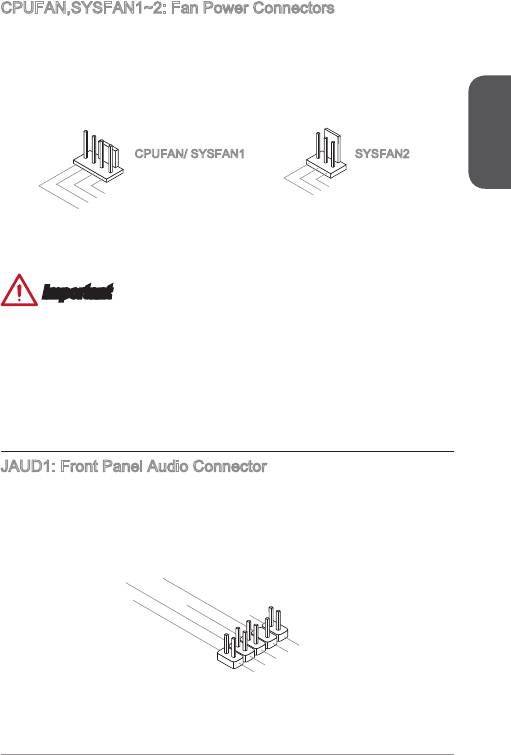
CPUFAN,SYSFAN~2: Fan Power Connectors
The fan power connectors support system cooling fans with +2V. If the motherboard
has a System Hardware Monitor chipset on-board, you must use a specially designed
fan with a speed sensor to take advantage of the CPU fan control. Remember to
connect all system fans. Some system fans may not connect to the motherboard and
will instead connect to the power supply directly. A system fan can be plugged into
any available system fan connector.
English
2
1
2.+12V
.Ground
3.Sens
4.Speed
e
C
ontro
l
1
2.+12V
.Ground
3.No
Us
e
CPUFAN/ SYSFAN SYSFAN2
Important
Please refer to your processor’s ocial website or consult your vendor to nd
recommended CPU heatsink.
These connectors support Smart Fan Control with liner mode. The Command
Center utility can be installed to automatically control the fan speeds according to
the CPU’s and system’s temperature.
If there are not enough ports on the motherboard to connect all system fans,
adapters are available to connect a fan directly to a power supply.
Before rst boot up, ensure that there are no cables impeding any fan blades.
JAUD: Front Panel Audio Connector
This connector allows you to connect the front audio panel located on your computer
®
case. This connector is compliant with the Intel
Front Panel I/O Connectivity Design
Guide.
10.Head
8.No
6.MI
4.NC
Pi
P
2
C D
n
hone
.Ground
etection
Detection
9.Head
7.SENSE_SEN
5.Head
3.MI
P
1.MI
hone
C R
P
C L
hone
L
D
R
•
•
•
•
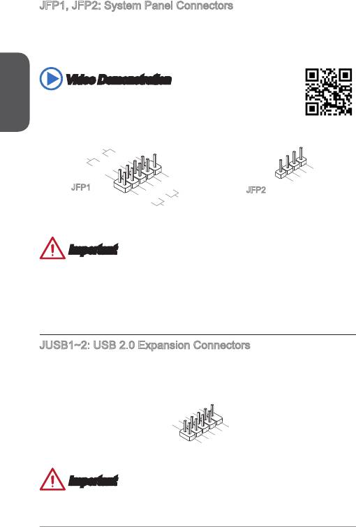
JFP, JFP2: System Panel Connectors
These connectors connect to the front panel switches and LEDs. The JFP
®
connector is compliant with the Intel
Front Panel I/O Connectivity Design Guide.
When installing the front panel connectors, please use the optional M-Connector to
simplify installation. Plug all the wires from the computer case into the M-Connector
and then plug the M-Connector into the motherboard.
English
Video Demonstration
Watch the video to learn how to Install front panel connectors.
http://youtu.be/DPELIdVNZUI
22
4.VCC5
3.Speaker
2.VCC5
1.Speaker
P
ower
P
Switc h
10.No
ower
LE
Pi
D
8.
n
6.
-
4.
+
2.
-
+
9.Res erve
7.
5.-
+
3.
1.
-
+
Reset
d
HDD
S
witch
LE
D
JFP
JFP2
Important
On the connectors coming from the case, pins marked by small triangles are
positive wires. Please use the diagrams above and the writing on the optional M-
Connectors to determine correct connector orientation and placement.
The majority of the computer case’s front panel connectors will primarily be
plugged into JFP.
JUSB~2: USB 2.0 Expansion Connectors
This connector is designed for connecting high-speed USB peripherals such as USB
HDDs, digital cameras, MP3 players, printers, modems, and many others.
1
0
8
.
.
NC
6
G
.
r
4
U
o
.
S
u
2
U
S
B
n
.
V
1
d
C
B
+
1
C
-
9
.
7
N
.
G
o
5
3
.
U
r
P
o
i
.
S
u
n
1
U
S
B
n
.
V
d
B
0
C
C
0
+
-
•
•
Important
Note that the VCC and GND pins must be connected correctly to avoid possible
damage.
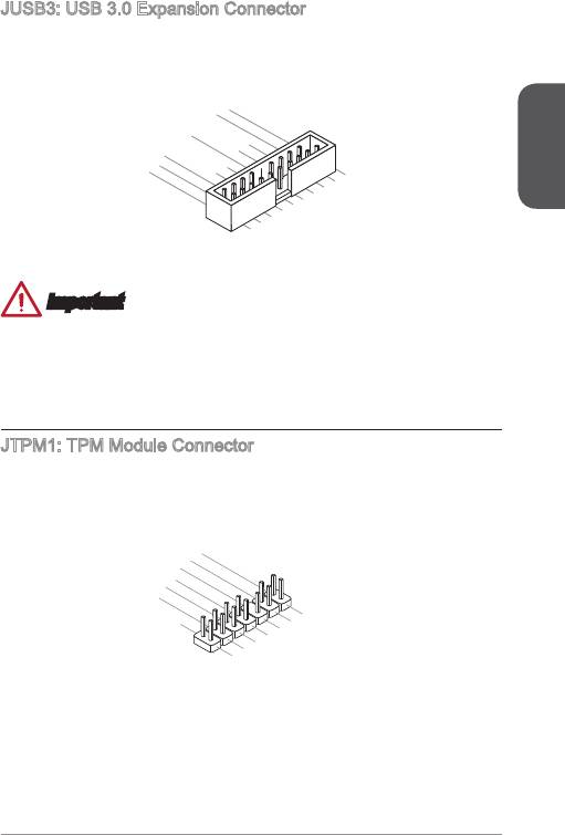
JUSB3: USB 3.0 Expansion Connector
The USB 3.0 port is backwards compatible with USB 2.0 devices. It supports data
transfer rates up to 5Gbits/s (SuperSpeed).
English
23
20.No
19.Power
18.USB3_RX_DN
17.USB3_RX_DP
Pi
16.Ground
n
15.USB3_TX_C_DN
14.USB3_TX_C_DP
13.Ground
12.USB2.0
11
. +
U
SB2.0
-
1.Power
2.USB3_RX_DN
3.USB3_RX_DP
4
.Ground
5.
6.USB3_TX_C_DP
U
7
SB3_TX_C_DN
8.
.Ground
9.
U
10.Ground
U
SB2.0
SB2.0
-
+
Important
Note that the VCC and GND pins must be connected correctly to avoid possible
damage.
To use a USB 3.0 device, you must connect the device to a USB 3.0 port through
an optional USB 3.0 compliant cable.
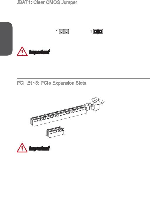
JTPM: TPM Module Connector
This connector connects to a TPM (Trusted Platform Module). Please refer to the
TPM security platform manual for more details and usages.
14.Ground
12.Ground
10.No
8.5V
6.Serial
Pi
4.3.3V
P
n
ower
2.3V
P
IR
Standby
ower
Q
power
13.LP
11
9.LP
.LPC
C
7.LP
Fram
5.LP
C a
a
3.LP
C a
ddres
ddres
e
1.LP
C a
ddres
C
ddres
s &
C C
Rese
s &
s &
data
loc
data
t
s &
k
data
p
data
p
in3
p
in2
pin0
in1
•
•
JBAT: Clear CMOS Jumper
There is CMOS RAM onboard that is external powered from a battery located on the
motherboard to save system conguration data. With the CMOS RAM, the system
can automatically boot into the operating system (OS) every time it is turned on. If
you want to clear the system conguration, set the jumpers to clear the CMOS RAM.
English
Keep Data Clear Data
Important
You can clear the CMOS RAM by shorting this jumper while the system is o.
Afterwards, open the jumper . Do not clear the CMOS RAM while the system is on
because it will damage the motherboard.
PCI_E~3: PCIe Expansion Slots
The PCIe slot supports the PCIe interface expansion card.
PCIe x6 Slot
PCIe x Slot
Important
When adding or removing expansion cards, always turn o the power supply and
unplug the power supply power cable from the power outlet. Read the expansion
card’s documentation to check for any necessary additional hardware or software
changes.
24
BIOS Setup
The default settings oer the optimal performance for system stability in normal
conditions. You may need to run the Setup program when:
■
An error message appears on the screen during the system booting up, and
requests you to run SETUP.
■
You want to change the default settings for customized features.
Important
English
•
Please load the default settings to restore the optimal system performance and
stability if the system becomes unstable after changing BIOS settings. Select the
"Restore Defaults" and press <Enter> in BIOS to load the default settings.
•
If you are unfamiliar with the BIOS settings, we recommend that you keep the
default settings to avoid possible system damage or failure booting due to
inappropriate BIOS conguration.
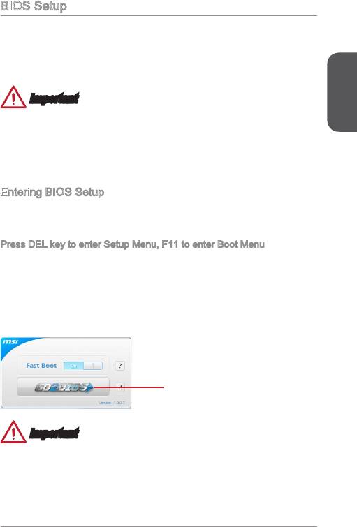
Entering BIOS Setup
Power on the computer and the system will start the Power On Self Test (POST)
process. When the message below appears on the screen, please <DEL> key to
enter BIOS:
Press DEL key to enter Setup Menu, F to enter Boot Menu
If the message disappears before you respond and you still need to enter BIOS,
restart the system by turning the computer OFF then back ON or pressing the
RESET button. You may also restart the system by simultaneously pressing <Ctrl>,
<Alt>, and <Delete> keys.
MSI additionally provides two methods to enter the BIOS setup. You can click the
“GO2BIOS” tab on “MSI Fast Boot” utility screen or press the physical “GO2BIOS"
button (optional) on the motherboard to enable the system going to BIOS setup
directly at next boot.
Click "GO2BIOS" tab on "MSI Fast
Boot" utility screen.
Important
Please be sure to install the “MSI Fast Boot” utility before using it to enter the BIOS
setup.
25
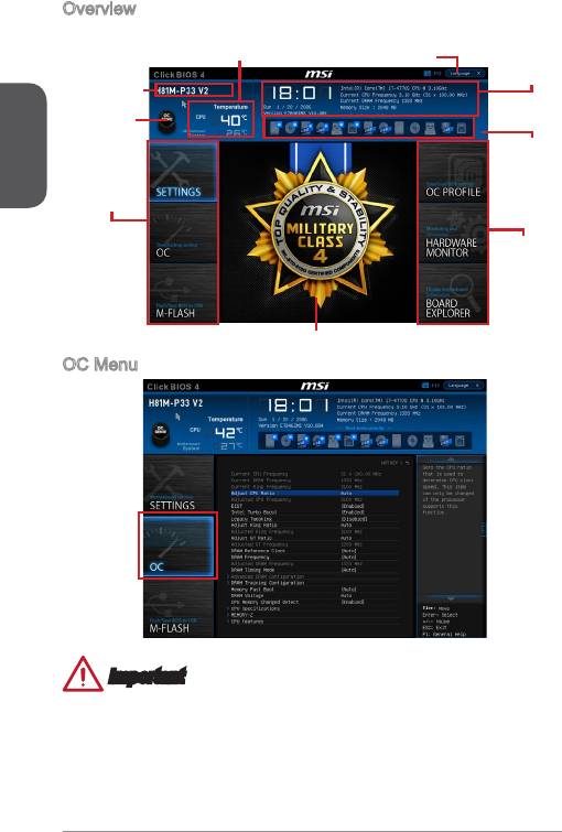
Overview
After entering BIOS, the following screen is displayed.
Temperature monitor
Language
System
information
Model name
English
Virtual OC
Genie Button
Boot device
priority bar
BIOS menu
selection
BIOS menu
selection
Menu display
OC Menu
Important
•
Overclocking your PC manually is only recommended for advanced users.
•
Overclocking is not guaranteed, and if done improperly, can void your warranty or
severely damage your hardware.
•
If you are unfamiliar with overclocking, we advise you to use OC Genie for easy
overclocking.
26
▶
Current CPU/ DRAM/ Ring Frequency
These items show the current frequencies of installed CPU, Memory and Ring.
Read-only.
▶
CPU Ratio Mode [Auto]
Selects the CPU Ratio operating mode.
[Auto] This setting will be congured automatically by BIOS.
[Fixed Mode] Fixes the CPU ratio.
[Dynamic Mode] CPU ratio will be changed dynamically according to the CPU
loading.
English
▶
Adjust CPU Ratio [Auto]
Sets the CPU ratio that is used to determine CPU clock speed. This item can only be
changed if the processor supports this function.
▶
Adjusted CPU Frequency
Shows the adjusted CPU frequency. Read-only.
▶
EIST [Enabled]
®
Enables or disables the Enhanced Intel
SpeedStep Technology.
▶
Intel Turbo Boost [Enabled]
®
Enables or disables the Intel
Turbo Boost. This item appears when the installed
CPU supports this function.
[Enabled] Enables this function to boost CPU performance automatically
above rated specications when system request the highest
performance state.
[Disabled] Disables this function.
▶
Adjust Ring Ratio [Auto]
Sets the ring ratio. The valid value range depends on the installed CPU.
▶
Adjusted Ring Frequency
Shows the adjusted Ring frequency. Read-only.
▶
Adjust GT Ratio [Auto]
Sets the integrated graphics ratio. The valid value range depends on the installed
CPU.
▶
Adjusted GT Frequency
Shows the adjusted integrated graphics frequency. Read-only.
▶
DRAM Frequency [Auto]
Sets the DRAM frequency. Please note the overclocking behavior is not guaranteed.
▶
Adjusted DRAM Frequency
Shows the adjusted DRAM frequency. Read-only.
27
▶
DRAM Timing Mode [Auto]
Selects the memory timing mode.
[Auto] DRAM timings will be determined based on SPD (Serial Presence
Detect) of installed memory modules.
[Link] Allows user to congure the DRAM timing manually for all memory
channel.
English
[UnLink] Allows user to congure the DRAM timing manually for respective
memory channel.
▶
Advanced DRAM Conguration
Press <Enter> to enter the sub-menu. This sub-menu will be activated after setting
[Link] or [Unlink] in “DRAM Timing Mode”. User can set the memory timing for each
memory channel. The system may become unstable or unbootable after changing
memory timing. If it occurs, please clear the CMOS data and restore the default
settings. (Refer to the Clear CMOS jumper/ button section to clear the CMOS data,
and enter the BIOS to load the default settings.)
▶
Memory Fast Boot [Auto]
Enables or disables the initiation and training for memory every booting.
[Auto] This setting will be congured automatically by BIOS.
[Enabled] Memory will completely imitate the archive of rst initiation and
rst training. After that, the memory will not be initialed and trained
when booting to accelerate the system booting time.
[Disabled] The memory will be initialed and trained every booting.
▶
DRAM Voltage [Auto]
Sets the memory voltage. If set to "Auto", BIOS will set memory voltage
automatically or you can set it manually.
▶
Spread Spectrum
This function reduces the EMI (Electromagnetic Interference) generated by
modulating clock generator pulses.
[Enabled] Enables the spread spectrum function to reduce the EMI
(Electromagnetic Interference) problem.
[Disabled] Enhances the overclocking ability of CPU Base clock.
Important
•
If you do not have any EMI problem, leave the setting at [Disabled] for optimal
system stability and performance. But if you are plagued by EMI, select the value
of Spread Spectrum for EMI reduction.
•
The greater the Spread Spectrum value is, the greater the EMI is reduced, and
the system will become less stable. For the most suitable Spread Spectrum value,
please consult your local EMI regulation.
•
Remember to disable Spread Spectrum if you are overclocking because even a
slight jitter can introduce a temporary boost in clock speed which may just cause
your overclocked processor to lock up.
28
▶
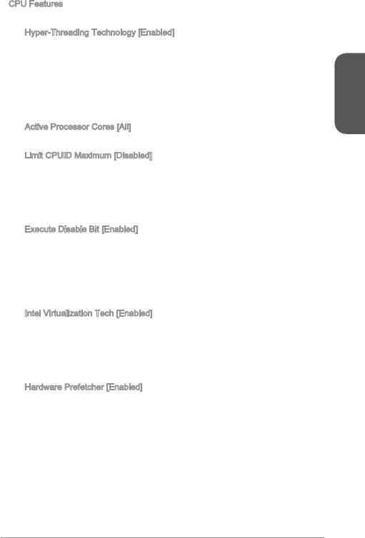
CPU Features
Press <Enter> to enter the sub-menu.
▶
Hyper-Threading Technology [Enabled]
The processor uses Hyper-Threading technology to increase transaction rates
and reduces end-user response times. Intel Hyper-Threading technology treats
the multi cores inside the processor as multi logical processors that can execute
instructions simultaneously. In this way, the system performance is highly
improved.
[Enable] Enables Intel Hyper-Threading technology.
[Disabled] Disables this item if the system does not support HT function.
English
▶
Active Processor Cores [All]
This item allows you to select the number of active processor cores.
▶
Limit CPUID Maximum [Disabled]
Enables or disables the extended CPUID value.
[Enabled] BIOS will limit the maximum CPUID input value to circumvent
boot problems with older operating system that do not support
the processor with extended CPUID value.
[Disabled] Use the actual maximum CPUID input value.
▶
Execute Disable Bit [Enabled]
Intel’s Execute Disable Bit functionality can prevent certain classes of malicious
“buer overow” attacks where worms attempt to execute code to damage the
system. It is recommended that keeps this item enabled always.
[Enabled] Enables NO-Execution protection to prevent the malicious
attacks and worms.
[Disabled] Disables this function.
▶
Intel Virtualization Tech [Enabled]
Enables or disables Intel Virtualization technology.
[Enabled] Enables Intel Virtualization technology and allows a platform
to run multiple operating systems in independent partitions.
The system can function as multiple systems virtually.
[Disabled] Disables this function.
▶
Hardware Prefetcher [Enabled]
Enables or disables the hardware prefetcher (MLC Streamer prefetcher).
[Enabled] Allows the hardware prefetcher to automatically pre-fetch
data and instructions into L2 cache from memory for tuning
the CPU performance.
[Disabled] Disables the hardware prefetcher.
29

▶
Adjacent Cache Line Prefetch [Enabled]
Enables or disables the CPU hardware prefetcher (MLC Spatial prefetcher).
[Enabled] Enables adjacent cache line prefetching for reducing the
cache latency time and tuning the performance to the specic
application.
[Disabled] Enables the requested cache line only.
English
▶
CPU AES Instructions [Enabled]
Enables or disables the CPU AES (Advanced Encryption Standard-New
Instructions) support. This item appears when a CPU supports this function.
[Enabled] Enables Intel AES support.
[Disabled] Disables Intel AES support.
▶
Intel Adaptive Thermal Monitor [Enabled]
Enables or disables the Intel adaptive thermal monitor function to protect the
CPU from overheating.
[Enabled] Throttles down the CPU core clock speed when the CPU is
over the adaptive temperature.
[Disabled] Disables this function.
▶
Intel C-State [Auto]
C-state is a processor power management technology dened by ACPI.
[Auto] This setting will be congured automatically by BIOS.
[Enabled] Detects the idle state of system and reduce CPU power
consumption accordingly.
[Disabled] Disable this function.
▶
CE Support [Disabled]
Enables or disables the CE function for power-saving in halt state. This item
appears when "Intel C-State" is enabled.
[Enabled] Enables CE function to reduce the CPU frequency and
voltage for power-saving in halt state.
[Disabled] Disables this function.
▶
Package C State limit [Auto]
This item allows you to select a CPU C-state mode for power-saving when
system is idle. This item appears when "Intel C-State" is enabled.
[Auto] This setting will be congured automatically by BIOS.
[C0~C7s] The power-saving level from high to low is C7s, C7, C6, C3,
C2, then C0.
[No limit] No C-state limit for CPU.
▶
LakeTiny Feature [Disabled]
Enables or disables Intel Lake Tiny feature with iRST for SSD. This item appears
when a installed CPU supports this function and "Intel C-State" is enabled.
[Enabled] Enhance the dynamic IO load adjusted performance for
accelerating the SSD speed.
[Disabled] Disables this feature.
30

Note: The following items will appear when "Intel Turbo Boost " is enabled.
▶
Long Duration Power Limit (W) [Auto]
Sets the long duration TDP power limit for CPU in Turbo Boost mode.
▶
Long Duration Maintained (s) [Auto]
Sets the maintaining time for "Long duration power Limit(W)".
▶
Short Duration Power Limit (W) [Auto]
Sets the short duration TDP power limit for CPU in Turbo Boost mode.
▶
CPU Current limit (A) [Auto]
English
Sets maximum current limit of CPU package in Turbo Boost mode. When the
current is over the specied limit value, the CPU will automatically reduce the
core frequency for reducing the current.
▶
/2/3/4-Core Ratio Limit [Auto]
These items only appear when a CPU that support this function is installed.
These items allow you to set the CPU ratios for dierent number of active cores
in turbo boost mode. These items appear when the installed processor supports
this function.
3

English
32
한국어
H8M-P33 V2/ H8M-E33 V2/ B85M-P33 V2/ B85M-E33 V2 시리즈 (MS-7846 v2.X)
Micro-ATX 메인보드를 선택해 주셔서 감사합니다. H8M-P33 V2/ H8M-E33 V2/
B85M-P33 V2/ B85M-E33 V2 시리즈 메인보드는 최적의 시스템 효율을 위해 Intel
H8/ B85 칩셋에 기반을 둔 제품입니다. 고급 Intel LGA50 프로세서에 적합하게 디
자인 된 H8M-P33 V2/ H8M-E33 V2/ B85M-P33 V2/ B85M-E33 V2 시리즈는 고성능
과 전문적인 데스크톱 플랫폼 솔루션을 제공합니다.
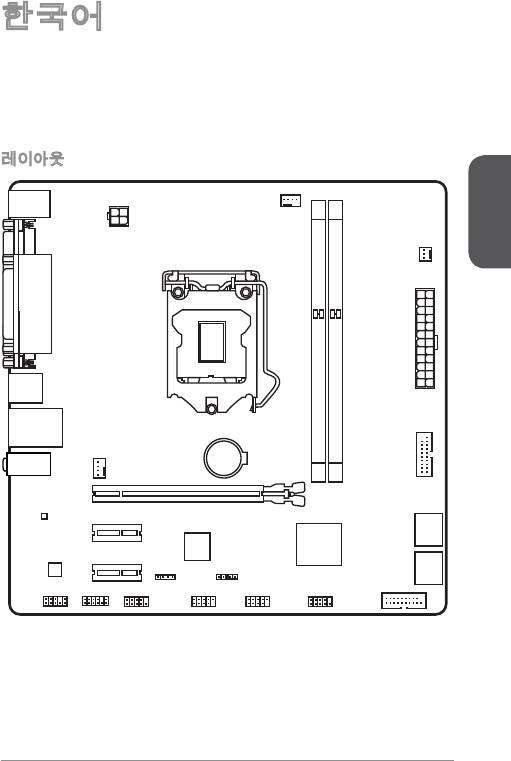
레이아웃
한국어
33
Top : mouse / k eybo ard
Bottom: USB 2.0 po rts
CPUFAN
JPWR2
SYSFAN 2
Top :
Paralle ortl p (opti onal)
Bottom:
DVI-D p ort (o ptio nal)
HDMI po rt (op tion al)
VGA port
JPWR1
USB3.0 port s
Top: LAN Ja ck
2
Bottom: USB 2.0 po rts
DIMM1
DIMM
optional)
(
T:Line-In
M:Line-Out
SYSFAN 1
B:Mic-In
JUSB3_2
PCI_E1
PCI_E2
3_4
TA
SA
PCI_E3
1_2
TA
JBAT1
JCI1
SA
JFP2
JUSB3_1 (op tion al)
JAUD1 JTPM1
COM1
JUSB2
JUSB1
JFP1
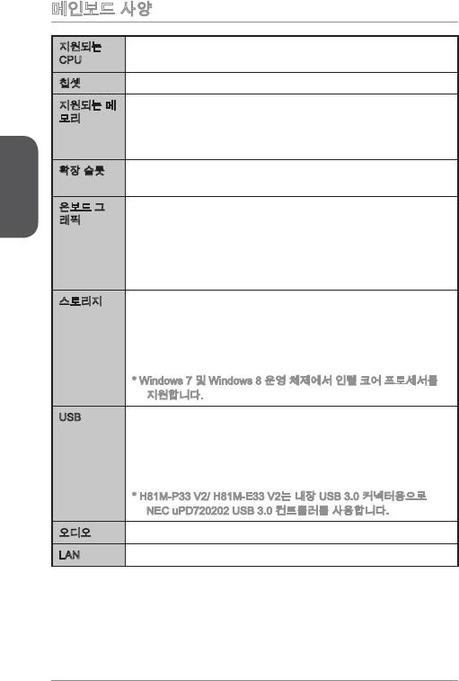
메인보드 사양
®
지원되는
■
LGA 50 소켓을 사용한 4세대 Intel
Core™ i7 / Core™ i5 /
CPU
®
®
Core™ i3 / Pentium
/ Celeron
프로세서를 지원합니다.
®
칩셋 Intel
H8/ B85 Express 칩셋■
지원되는 메
■
DDR3 메모리 슬롯 2개, 최대 6GB 지원
모리
■
DDR3 600/ 333/ 066 MHz 지원
■
듀얼 채널 메모리 지원
■
non-ECC, un-buered 메모리 지원
한국어
확장 슬롯 PCIe x6 슬롯 개
■
■
PCIe 2.0 x 슬롯 2개
온보드 그
■
VGA 포트 개, 최대 920x200 @ 60Hz, 24bpp 해상도 지원
래픽
■
HDMI 포트 개 (옵션), 최대 4096x260@24Hz, 24bpp/
2560x600@60Hz, 24bpp/ 920x080@60Hz, 36bpp 해상
도 지원
■
DVI-D 포트 개 (옵션), 최대 920x200 @ 60Hz, 24bpp 해상
도 지원
스토리지 Intel H8/ B85 Express 칩셋
■
-
SATA 6Gb/s 포트 2개 (SATA~2)
-
SATA 3Gb/s 포트 2개 (SATA3~4)
-
Intel Rapid Start Technology 지원 (옵션)*
-
Intel Smart Connect Technology 지원
* Windows 7 및 Windows 8 운영 체제에서 인텔 코어 프로세서를
지원합니다.
USB Intel H8/ B85 Express 칩셋
■
-
USB 3.0 포트 4개 (후면 패널에 2포트, 내부 USB 커넥터를
통해 2포트 사용*)
-
USB 2.0 포트 8개 (후면 패널에 4포트, 내부 USB 커넥터를
통해 4포트 사용)
* H8M-P33 V2/ H8M-E33 V2는 내장 USB 3.0 커넥터용으로
NEC uPD720202 USB 3.0 컨트롤러를 사용합니다.
®
오디오 Realtek
ALC887 코덱■
®
LAN Realtek
RTL8G Gigabit LAN 컨트롤러■
34
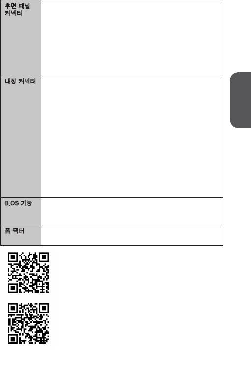
후면 패널
■
PS/2 키보드/ 마우스 포트 개
커넥터
■
VGA 포트 개
■
페러렐 포트 개 (옵션)
■
DVI-D 포트 개 (옵션)
■
HDMI 포트 개 (옵션)
■
USB 2.0 포트 4개
■
USB 3.0 포트 2개
■
LAN (RJ45) 포트 개
■
오디오 잭 3개
내장 커넥터 24 핀 ATX 메인 전원 커넥터 개
■
■
4 핀 ATX 2V 전원 커넥터 개
■
SATA 6Gb/s 커넥터 2개
■
SATA 3Gb/s 커넥터 2개
한국어
■
USB 2.0 커넥터 2개 (외 USB 2.0 4포트 지원)
■
USB 3.0 커넥터 개 (외 USB 3.0 2포트 지원)
■
4 핀 CPU 팬 커넥터 개
■
4 핀 시스템 팬 커넥터 개
■
3 핀 시스템 팬 커넥터 개
■
전면 패널 오디오 커넥터 개
■
시리얼 포트 커넥터 개
■
TPM 커넥터 개
■
시스템 패널 커넥터 2개
■
섀시 침입 커넥터 개
■
CMOS 클리어 점퍼 개
BIOS 기능 UEFI AMI BIOS
■
■
ACPI 5.0, PnP .0a, SM BIOS 2.7, DMI 2.0
■
다국어
폼 팩터 Micro-ATX 폼 팩터
■
■
8.9 in. x 9.0 in. (22.6 cm x 22.8 cm)
CPU에 대한 최신 정보는
http://www.msi.com/service/cpu-support/를 참조하세요.
호환 가능한 부품에 대한 자세한 정보는
http://www.msi.com/service/test-report/를 참조하세요.
35
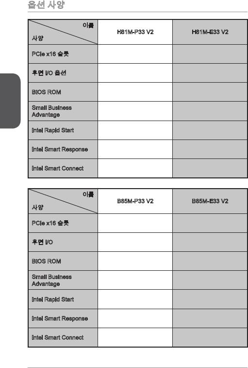
옵션 사양
이름
H8M-P33 V2 H8M-E33 V2
사양
PCIe x6 슬롯 Gen2 Gen2
후면 I/O 옵션 페러렐, DVI-D HDMI
한국어
BIOS ROM 64Mb 64Mb
Small Business
지원하지 않음 지원하지 않음
Advantage
Intel Rapid Start 지원하지 않음 지원하지 않음
Intel Smart Response 지원하지 않음 지원하지 않음
Intel Smart Connect 지원함 지원함
이름
B85M-P33 V2 B85M-E33 V2
사양
PCIe x6 슬롯 Gen3 Gen3
후면 I/O 페러렐, DVI-D HDMI
BIOS ROM 28Mb 28Mb
Small Business
지원함 지원함
Advantage
Intel Rapid Start 지원함 지원함
Intel Smart Response 지원하지 않음 지원하지 않음
Intel Smart Connect 지원함 지원함
36
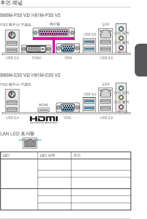
후면 패널
B85M-P33 V2/ H8M-P33 V2
PS/2 마우스/ 키보드
LAN페러렐
라인 입력
USB 3.0
라인 출력
마이크
USB 2.0
DVI-D
VGA
USB 2.0
한국어
B85M-E33 V2/ H8M-E33 V2
PS/2 마우스/ 키보드
LAN
라인 입력
USB 3.0
라인 출력
HDMI
마이크
USB 2.0
VGA
USB 2.0
LAN LED 표시등
LINK/ACT
SPEED
LED
LED
LED LED 상태 조건
LAN이 올바르게 연결되지 않았
꺼짐
습니다.
Link/ Activity LED
노란색 LAN이 올바르게 연결되었습니다.
(링크/ 통신 LED)
컴퓨터가 LAN으로 정상적인 통신
깜빡임
중입니다.
꺼짐 0 Mbps 속도로 연결되었습니다.
Speed LED
녹색 00 Mbps 속도로 연결되었습니다.
(속도 LED)
오렌지색 Gbps 속도로 연결되었습니다.
37
®
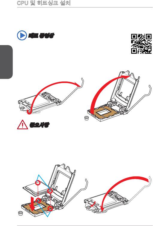
CPU 및 히트싱크 설치
CPU 설치시, CPU 히트싱크를 반드시 설치하세요. CPU 히트싱크는 과열을 방지하고
시스템 성능을 유지하는데 꼭 필요합니다.아래의 순서에 따라 CPU 및 히트싱크를 정
확하게 설치하세요. 잘못 설치할 경우 CPU와 메인보드가 손상될수 있습니다.
데모 동영상
CPU 및 히트싱크 설치에 대한 동영상을 참조하려면 아래의 웹사이트
를 방문하세요.
http://youtu.be/bf5La099urI
한국어
. 로드 레버를 전부 위로 올려줍니다.
2. 로드 레버를 전부 위로 올리면 로드 플레이트가 자동으로 열려집니다.
중요사항
소켓 또는 CPU 아래 부분의 손상에 주의하세요.
3. 요철을 올바른 방향으로 소켓 정렬 키에 맞춘 후 CPU를 소켓에 내려놓습니다.
CPU가 소켓에 제대로 장착되었는지 확인하세요.
4. 로드 플레이트를 닫고 노브에 고정한 후 로드 레버를 아래로 눌러 고정탭에 고정
합니다.
CPU 요철
정렬 키
38
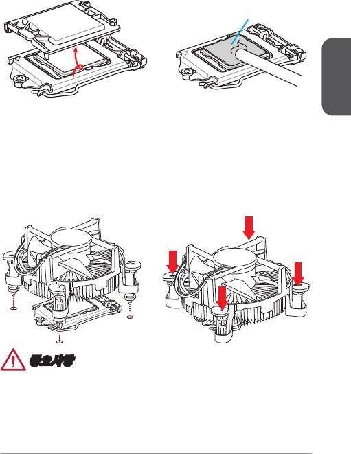
5. 로드 레버를 아래로 누르면 PnP 캡이 CPU 소켓에서 자동으로 분리됩니다. PnP
캡을 버리지 마세요. CPU를 소켓에서 제거할시에 PnP 캡을 다시 장착하세요.
6. CPU의 과열을 방지하고 열이 잘 발산되도록 CPU의 상단에 서멀 페이스트(또는
서멀 테이프)를 알맞게 발라줍니다.
서멀 페이스트
한국어
7. 메인보드에 CPU 팬 커넥터를 장착합니다.
8. 팬의 선이 팬 커넥터 쪽을 향하고 고정핀이 메인보드의 홀에 꼭 맞게 히트싱크를
메인보드에 장착합니다.
9. 4개의 고정핀이 메인보드의 홀에 완전히 박힐 때까지 히트싱크를 누릅니다. 4개
의 고정핀을 눌러 히트싱크를 고정합니다. 고정핀이 올바른 위치에 고정되었다면
닫히는 소리가 들립니다.
0. 고정핀의 후크가 올바로 고정되었는지 확인합니다.
. 마지막으로 CPU 팬 케이블을 메인보드의 CPU 팬 커넥터에 연결합니다.
중요사항
•
시스템을 켜기 전에 CPU 쿨러가 단단히 설치되었는지 확인합니다.
•
CPU가 설치되어 있지 않은 경우, 손상되지 않도록 항상 플라스틱 캡으로 CPU 소
켓 핀을 보호하세요.
•
CPU와 히트싱크/ 쿨러를 별도로 구입하였을 경우, 설치에 대한 자세한 내용은 히트
싱크/ 쿨러 패키지에 있는 설명서를 참조하세요.
39
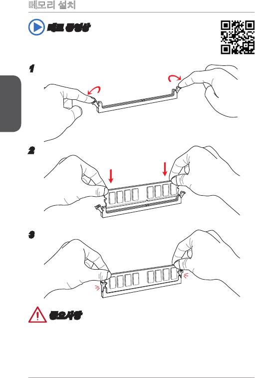
메모리 설치
데모 동영상
메모리 설치에 대한 동영상을 참조하려면 아래의 웹사이트를 방문하세요.
http://youtu.be/76yLtJaKlCQ
한국어
2
3
중요사항
•
DDR3 메모리 모듈은 DDR2와 서로 호환되지 않으며 ,표준 DDR3는 하위호환이 되
지 않습니다.항상 DDR3 DIMM 슬롯에 DDR3 메모리 모듈을 설치해야 합니다.
•
시스템의 안정성을 확보하기 위하여 듀얼 채널 모드에서는 타입과 용량이 동일한
메모리 모듈을 사용해야 합니다.
40


