MSI Wind Board D510 – page 2
Manual for MSI Wind Board D510
English
En-11
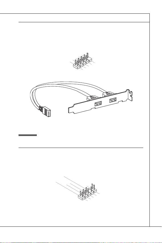
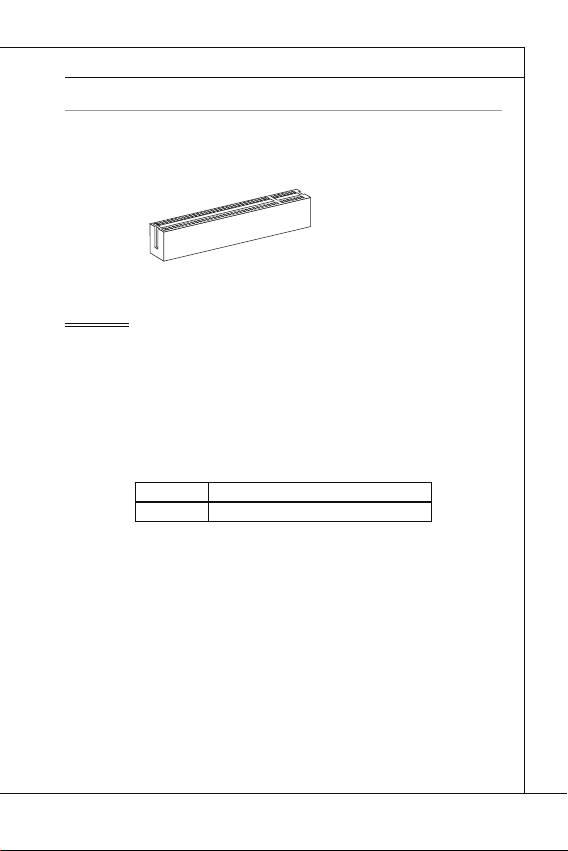
Front USB Connector: JUSB1 / JUSB2
Front USB Connector: JUSB1 / JUSB2
®
This connector, compliant with Intel
I/O Connectivity Design Guide, is ideal for con-
necting high-speed USB interface peripherals such as USB HDD, digital cameras, MP3
players, printers, modems and the like.
1
.
V
C
USB 2.0 Bracket (optional)
C
3
.
U
S
B
D
-
1
0
.
U
S
B
O
C
9
.
7
N
.
5
G
o
.
r
P
U
o
i
S
u
B
n
D
d
+
n
8
.
6
G
.
U
r
4
o
.
S
u
2
U
B
n
.
S
V
D
d
B
C
D
+
C
-
Important
Important
Note that the pins of VCC and GND must be connected correctly to avoid possible
damage.
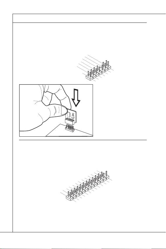
Front Panel Audio Connector: JAUD1
Front Panel Audio Connector: JAUD1
®
This connector allows you to connect the front panel audio and is compliant with Intel
Front Panel I/O Connectivity Design Guide.
3
.
1
M
.
M
I
C
I
C
R
L
1
0
.
H
e
a
d
P
h
o
n
e
D
e
t
e
c
t
i
o
n
9
.
7
H
5
.
S
e
a
.
H
E
d
e
N
P
a
S
h
d
E
o
P
_
n
h
S
e
o
E
n
N
e
D
R
L
8
.
6
N
.
4
M
o
.
I
P
2
P
C
i
n
.
R
G
D
E
r
e
o
S
t
u
E
e
n
N
c
d
t
C
i
o
E
n
#
En-12
MS-7618 Mainboard
▍
MS-7618 Mainboard
TPM Module connector: JTPM1
TPM Module connector: JTPM1
This connector connects to a TPM (Trusted Platform Module) module (optional).
Please refer to the TPM security platform manual for more details and usages.
1
0
.
N
o
P
i
n
1
1
4
2
.
G
.
G
r
o
8
r
u
.
o
n
6
5
u
.
V
n
d
4
S
e
P
d
.
3
r
o
.
i
3
a
w
V
l
e
I
R
r
P
o
Q
w
e
r
2
.
3
V
S
t
a
n
d
b
y
p
o
w
e
r
5
.
3
L
.
L
P
1
.
P
C
L
C
a
P
R
d
C
d
C
e
r
s
e
l
s
o
e
s
c
t
k
&
d
a
t
a
p
i
n
0
1
1
9
.
.
L
7
L
P
.
P
C
L
C
P
a
C
a
d
d
d
a
d
r
d
r
e
d
e
s
r
s
s
e
s
&
s
s
&
d
&
d
a
a
t
d
t
a
a
a
p
t
a
p
i
n
i
p
n
i
2
n
1
3
1
3
.
L
P
C
F
r
a
m
e
Parallel Port Header: JLPT1
Parallel Port Header: JLPT1
This connector is used to connect an optional parallel port bracket. The parallel port is a
standard printer port that supports Enhanced Parallel Port (EPP) and Extended Capa-
bilities Parallel Port (ECP) mode.
2
2
6
4
.
N
2
.
G
o
2
2
.
G
r
P
0
o
i
1
u
n
.
8
G
r
o
n
1
.
r
6
G
u
d
o
n
1
.
r
u
4
G
o
d
n
1
.
r
u
d
2
G
o
n
1
.
r
u
d
0
G
o
n
8
.
G
r
d
.
o
u
6
L
r
u
n
d
.
P
o
n
4
P
T
u
d
.
I
E
N
_
n
2
2
S
d
.
R
I
5
T
L
A
2
.
R
#
I
3
S
F
#
N
2
.
L
D
#
1
P
C
#
1
.
B
E
T
1
9
7
.
A
U
1
.
C
S
5
P
Y
1
.
P
R
K
3
#
1
.
P
R
N
1
N
D
9
.
R
7
.
P
R
N
D
7
P
6
.
R
N
D
5
P
5
3
.
N
D
P
R
D
4
.
P
R
N
3
1
D
.
R
R
N
2
N
D
S
1
T
D
B
0
#
English
En-13
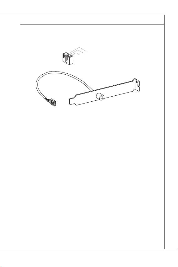
S/PDIF-Out Connector: JSP1
S/PDIF-Out Connector: JSP1
This connector is used to connect S/PDIF (Sony & Philips Digital Interconnect Format)
interface for digital audio transmission.
3
.
2
G
.
r
1
S
o
.
P
u
V
D
n
C
I
d
C
F
S/PDIF Bracket (Optional)
En-14
MS-7618 Mainboard
▍
MS-7618 Mainboard
JUMPERS
JUMPERS
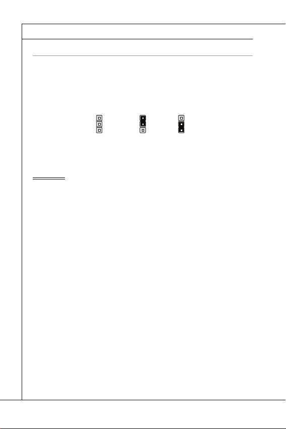
Clear CMOS Jumper: JBAT1
Clear CMOS Jumper: JBAT1
There is a CMOS RAM onboard that has a power supply from an external battery to keep
the data of system confi guration. With the CMOS RAM, the system can automatically
boot OS every time it is turned on. If you want to clear the system confi guration, set the
jumper to clear data.
JBAT1
JBAT1 Keep Data Clear Data
1 11
Important
Important
You can clear CMOS by shorting 2-3 pin while the system is off . Then return to 1-
2 pin position. Avoid clearing the CMOS while the system is on; it will damage the
mainboard.
English
En-15
SLOTS
SLOTS
PCI (Peripheral Component Interconnect) Slot
PCI (Peripheral Component Interconnect) Slot
The PCI slot supports LAN card, SCSI card, USB card, and other add-on cards that
comply with PCI specifi cations.
32-bit PCI Slot
Important
Important
When adding or removing expansion cards, make sure that you unplug the power sup-
ply fi rst. Meanwhile, read the documentation for the expansion card to confi gure any
necessary hardware or software settings for the expansion card, such as jumpers,
switches or BIOS confi guration.
PCI Interrupt Request Routing
PCI Interrupt Request Routing
The IRQ, acronym of interrupt request line and pronounced I-R-Q, are hardware lines
over which devices can send interrupt signals to the microprocessor. The PCI IRQ pins
are typically connected to the PCI bus pins as follows:
Order1 Order2 Order3 Order4
Order1 Order2 Order3 Order4
PCI Slot1 INT B# INT C# INT D# INT A#

En-16
MS-7618 Mainboard
▍
MS-7618 Mainboard
BIOS SETUP
BIOS SETUP
This chapter provides basic information on the BIOS Setup program and allows you to
confi gure the system for optimum use. You may need to run the Setup program when:
An error message appears on the screen during the system booting up, and
requests you to run BIOS SETUP.
You want to change the default settings for customized features.
Important
■
■
Important
•
The items under each BIOS category described in this chapter are under continuous
update for better system performance. Therefore, the description may be slightly dif-
ferent from the latest BIOS and should be held for reference only.
•
Upon boot-up, the 1st line appearing after the memory count is the BIOS version. It is
usually in the format:
A7618IMS V1.0 020110 where:
1st digit refers to BIOS maker as A = AMI, W = AWARD, and P = PHOENIX.
2nd - 5th digit refers to the model number.
6th digit refers to the chipset as I = Intel, N = NVIDIA, A = AMD and V = VIA.
7th - 8th digit refers to the customer as MS = all standard customers.
V1.0 refers to the BIOS version.
020110 refers to the date this BIOS was released.

English
En-17
Entering Setup
Entering Setup
Power on the computer and the system will start POST (Power On Self Test) process.
When the message below appears on the screen, press <DEL> key to enter Setup.
Press DEL to enter SETUP
Press DEL to enter SETUP
If the message disappears before you respond and you still wish to enter Setup, restart
the system by turning it OFF and On or pressing the RESET button. You may also re-
start the system by simultaneously pressing <Ctrl>, <Alt>, and <Delete> keys.
Getting Help
Getting Help
After entering the Setup menu, the fi rst menu you will see is the Main Menu.
Main Menu
Main Menu
The main menu lists the setup functions you can make changes to. You can use the
arrow keys ( ↑↓ ) to select the item. The on-line description of the highlighted setup
function is displayed at the bottom of the screen.
Sub-Menu
Sub-Menu
If you fi nd a right pointer symbol appears to the left of certain fi elds that means a sub-
menu can be launched from this fi eld. A sub-menu contains additional options for a
fi eld parameter. You can use arrow keys ( ↑↓ ) to highlight the fi eld and press <Enter>
to call up the sub-menu. Then you can use the control keys to enter values and move
from fi eld to fi eld within a sub-menu. If you want to return to the main menu, just press
the <Esc >.
General Help <F1>
General Help <F1>
The BIOS setup program provides a General Help screen. You can call up this screen
from any menu by simply pressing <F1>. The Help screen lists the appropriate keys to
use and the possible selections for the highlighted item. Press <Esc> to exit the Help
screen.
En-18
MS-7618 Mainboard
▍
MS-7618 Mainboard
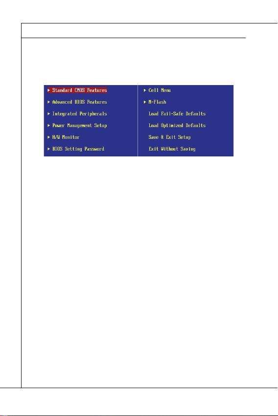
The Main Menu
The Main Menu
Once you enter BIOS CMOS Setup Utility, the Main Menu will appear on the screen.
The Main Menu allows you to select from the setup functions and two exit choices.
Use arrow keys to select among the items and press <Enter> to accept or enter the
sub-menu.
Standard CMOS Features
Standard CMOS Features
Use this menu for basic system confi gurations, such as time, date etc.
Advanced BIOS Features
Advanced BIOS Features
Use this menu to setup the items of the BIOS special enhanced features.
Integrated Peripherals
Integrated Peripherals
Use this menu to specify your settings for integrated peripherals.
Power Management Setup
Power Management Setup
Use this menu to specify your settings for power management.
H/W Monitor
H/W Monitor
This entry shows your PC health status.
BIOS Setting Password
BIOS Setting Password
Use this menu to set the password for BIOS.
Cell Menu
Cell Menu
Use this menu to specify your settings for frequency/voltage control and overclocking.
M-Flash
▶
▶
▶
▶
▶
▶
▶
▶
M-Flash
Use this menu to read/ fl ash (or backup) the BIOS from (to) storage drive (FAT/ FAT32
format only).

English
En-19
Load Fail-Safe Defaults
Load Fail-Safe Defaults
Use this menu to load the default values set by the BIOS vendor for stable system
performance.
Load Optimized Defaults
Load Optimized Defaults
Use this menu to load the default values set by the mainboard manufacturer specifi cally
for optimal performance of the mainboard.
Save & Exit Setup
Save & Exit Setup
Save changes to CMOS and exit setup.
Exit Without Saving
▶
▶
▶
▶
Exit Without Saving
Abandon all changes and exit setup.
En-20
MS-7618 Mainboard
▍
MS-7618 Mainboard
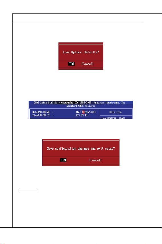
When enter the BIOS Setup utility, follow the processes below for general use.
1.
Load Optimized Defaults : Use control keys (↑↓) to highlight the Load Optimized
Defaults fi eld and press <Enter> , a message as below appears:
Select [Ok] and press Enter to load the default settings for optimal system perfor-
mance.
2.
Setup Date/ Time : Select the Standard CMOS Features and press <Enter> to enter
the Standard CMOS Features-menu. Adjust the Date, Time fi elds.
3.
Save & Exit Setup : Use control keys (↑↓) to highlight the Save & Exit Setup fi eld
and press <Enter> , a message as below appears:
Select [Ok] and press Enter to save the confi gurations and exit BIOS Setup utility.
Important
Important
The confi guration above are for general use only. If you need the detailed settings of
BIOS, please see the English manual on MSI website.
English
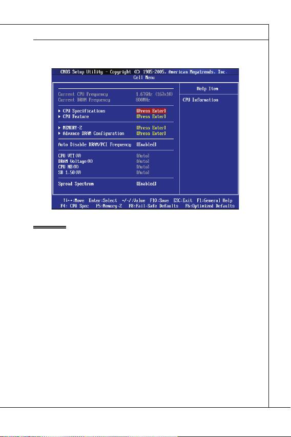
Cell Menu Introduction : This menu is for advanced user who want to overclock the
mainboard.
En-21
Important
Important
Change these settings only if you are familiar with the chipset.
Current CPU / DRAM Frequency
Current CPU / DRAM Frequency
These items show the current frequencies of CPU and Memory. Read-only.
CPU Specifi cations
CPU Specifi cations
Press <Enter> to enter the sub-menu. This submenu shows the information of installed
CPU.
CPU Technology Support
CPU Technology Support
Press <Enter> to enter the sub-menu. In this sub-menu, it shows the installed CPU
technologies. Read only.
CPU Feature
CPU Feature
Press <Enter> to enter the sub-menu.
Hyper-Threading Function
4.
▶
▶
▶
▶
▶
Hyper-Threading Function
The processor uses Hyper-Threading technology to increase transaction rates and
reduces end-user response times. The technology treats the two cores inside the
processor as two logical processors that can execute instructions simultaneously. In
this way, the system performance is highly improved. If you disable the function, the
processor will use only one core to execute the instructions. Please disable this item
if your operating system doesn’t support HT Function, or unreliability and instability
may occur.

En-22
MS-7618 Mainboard
▍
MS-7618 Mainboard
Important
Important
Enabling the functionality of Hyper-Threading Technology for your computer system
requires ALL of the following platform Components:
®
CPU: An Intel
Processor with HT Technology;
®
Chipset: An Intel
Chipset that supports HT Technology;
BIOS: A BIOS that supports HT Technology and has it enabled;
OS: An operating system that supports HT Technology.
For more information on Hyper-threading Technology, go to:
http://www.intel.com/products/ht/hyperthreading_more.htm
Execute Bit Support
Execute Bit Support
Intel’s Execute Disable Bit functionality can prevent certain classes of malicious
“buff er overfl ow” attacks when combined with a supporting operating system. This
functionality allows the processor to classify areas in memory by where application
code can execute and where it cannot. When a malicious worm attempts to insert
code in the buff er, the processor disables code execution, preventing damage or
worm propagation.
Set Limit CPUID MaxVal to 3
Set Limit CPUID MaxVal to 3
The Max CPUID Value Limit is designed limit the listed speed of the processor to
older operating systems.
Memory-Z
Memory-Z
Press <Enter> to enter the sub-menu.
DIMM1~2 Memory SPD Information
DIMM1~2 Memory SPD Information
Press <Enter> to enter the sub-menu. The sub-menu displays the informations of
installed memory.
Advance DRAM Confi guration
Advance DRAM Confi guration
When the DRAM Timing Mode is set to [Manual], this sub-menu will available. Press
<Enter> to enter the sub-menu.
DRAM Timing Mode
DRAM Timing Mode
Select whether DRAM timing is controlled by the SPD (Serial Presence Detect) EEP-
ROM on the DRAM module. Setting to [Auto] enables DRAM timings and the fol-
lowing “Advance DRAM Confi guration” sub-menu to be determined by BIOS based
on the confi gurations on the SPD. Selecting [Manual] allows users to confi gure the
DRAM timings and the following related “Advance DRAM Confi guration” sub-menu
manually.
CAS Latency (CL)
•
•
•
•
▶
▶
▶
▶
▶
▶
▶
CAS Latency (CL)
This controls the CAS latency, which determines the timing delay (in clock cycles)
before SDRAM starts a read command after receiving it.

English
En-23
tRCD
tRCD
When DRAM is refreshed, both rows and columns are addressed separately. This
setup item allows you to determine the timing of the transition from RAS (row ad-
dress strobe) to CAS (column address strobe). The less the clock cycles, the faster
the DRAM performance.
tRP
tRP
This setting controls the number of cycles for Row Address Strobe (RAS) to be
allowed to precharge. If insuffi cient time is allowed for the RAS to accumulate its
charge before DRAM refresh, refresh may be incomplete and DRAM may fail to
retain data. This item applies only when synchronous DRAM is installed in the sys-
tem.
tRAS
tRAS
This setting determines the time RAS takes to read from and write to memory cell.
Auto Disable DRAM/PCI Frequency
Auto Disable DRAM/PCI Frequency
When set to [Enabled], the system will remove (turn off ) clocks from empty DIMM/ PCI
slots to minimize the electromagnetic interference (EMI).
CPU VTT (V)/ DRAM Voltage (V)/ CPU NB (V)/ SB 1.50 (V)
CPU VTT (V)/ DRAM Voltage (V)/ CPU NB (V)/ SB 1.50 (V)
These items are used to adjust the voltage of CPU, DRAM, CPU NB and SB.
Spread Spectrum
Spread Spectrum
When the mainboard’s clock generator pulses, the extreme values (spikes) of the pulses
create EMI (Electromagnetic Interference). The Spread Spectrum function reduces the
EMI generated by modulating the pulses so that the spikes of the pulses are reduced
to fl atter curves.
Important
▶
▶
▶
▶
▶
▶
Important
•
If you do not have any EMI problem, leave the setting at [Disabled] for optimal system
stability and performance. But if you are plagued by EMI, select the value of Spread
Spectrum for EMI reduction.
•
The greater the Spread Spectrum value is, the greater the EMI is reduced, and the
system will become less stable. For the most suitable Spread Spectrum value, please
consult your local EMI regulation.
•
Remember to disable Spread Spectrum if you are overclocking because even a slight
jitter can introduce a temporary boost in clock speed which may just cause your over-
clocked processor to lock up.

En-24
MS-7618 Mainboard
▍
MS-7618 Mainboard
SOFTWARE INFORMATION
SOFTWARE INFORMATION
Take out the Driver/Utility DVD that is included in the mainboard package, and place
it into the DVD-ROM drive. The installation will auto-run, simply click the driver or util-
ity and follow the pop-up screen to complete the installation. The Driver/Utility DVD
contains the:
Driver menu : The Driver menu shows the available drivers. Install the driver by
your desire and to activate the device.
Utility menu : The Utility menu shows the software applications that the mainboard
supports.
WebSite menu : The WebSite menu shows the necessary websites.
Important
-
-
-
Important
Please visit the MSI website to get the latest drivers and BIOS for better system per-
formance.

Deutsch
Deutsch
Europe version
Wind Board
Wind Board
D510/ D410
D510/ D410
Serie
Serie

De-2
MS-7618 Mainboard
▍
MS-7618 Mainboard
SPEZIFICATIONEN
SPEZIFICATIONEN
P
P
rozessoren
rozessoren
®
Unterstützt Intel
Atom CPU D510/ D410
Die extremalen Taktfrequenz des Basetakts
Die extremalen Taktfrequenz des Basetakts
100 MHZ
Chipsatz
Chipsatz
®
Intel
NM10 Chipsatz
Speicher
Speicher
DDR2 800 SDRAM (max. 4GB)
2 DDR2 DIMMs (240Pin / 1,8V), Einkanal
*(Weitere Informationen zu kompatiblen Speichermodulen fi nden Sie unter
http://www.msi.com/index.php?func=testreport)
LAN
LAN
®
Unterstützt Realtek
RTL8103EL 10/100 Mb/s
®
Unterstützt Realtek
RTL8111DL 10/100/1000 Mb/s (optional)
Unterstützt ACPI Stromsparfunktion
Audio
Audio
®
Onboard Soundchip Realtek
ALC888S
6-Kanal Audio-Ausgang
SATA
SATA
®
2 SATA 3 Gb/s Anschlüsse über Intel
NM10
Anschlüsse
■
■
■
■
■
■
■
■
■
■
■
Anschlüsse
■
Hintere Ein-/ und Ausgänge
‑
1 PS/2 Mausanschluss
‑
1 PS/2 Tastaturanschlus
‑
1 Serieller Anschluss
‑
1 VGA Anschluss
‑
4 USB 2.0 Anschlüsse
‑
1 RJ-45 Anschluss
‑
3 Audiobuchsen
■
On-Board Stiftleiste/ Anschlüsse
‑
2 USB 2.0 Stiftleisten
‑
1 Parallele Stiftleiste
‑
1 Audio Stiftleiste für Gehäuse Audio Ein-/ Ausgänge
‑
1 S/PDIF-Ausgang Stiftleiste
‑
1 Gehäusekontaktschalter
‑
1 TPM Stiftleiste

Deutsch
De-3
S
S
teckplätze
teckplätze
1 PCI-Steckplatz
Unterstützt 3,3V/ 5V PCI Bus Interface
Form Faktor
Form Faktor
Mini-ITX (17,0cm X 17,0cm)
M
M
ontage
ontage
■
■
■
■
4 Montagebohrungen
Wenn Sie für Bestellungen von Zubehör Teilenummern benötigen, fi nden Sie diese auf
unserer Produktseite unter http://www.msi.com/index.php
De-4
MS-7618 Mainboard
▍
MS-7618 Mainboard
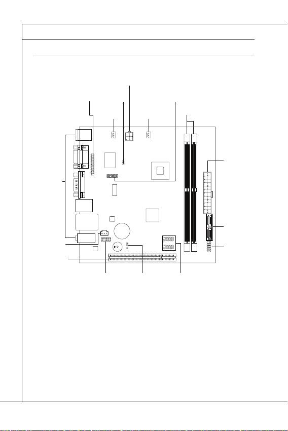
KOMPONENTEN-ÜBERSICHT
KOMPONENTEN-ÜBERSICHT
Rücktafel
Rücktafel,
De-8
DDR2
DDR2, De-5
JCI1
JCI1, De-9
JPWR1
JPWR1, De-7
JTPM1
JTPM1, De-12
SATA
SATA, De-9
SYSFAN1
SYSFAN1, De-10
JFP1
JFP1, De-10
JUSB1~2
JUSB1~2, De-11
PCI
PCI, De-15
JPWR2
JPWR2, De-7
JBAT1
JBAT1, De-14
SYSFAN2
SYSFAN2,
De-10
JLPT1
JLPT1, De-12
JAUD1
JAUD1, De-11
JSP1
JSP1, De-13
Deutsch
De-5
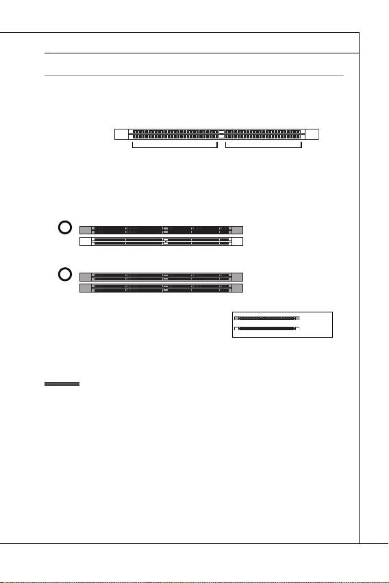
SPEICHER
SPEICHER
Diese DIMM-Steckplätze nehmen Arbeitsspeichermodule auf. Die neusten Infor-
mationen über kompatible Bauteile fi nden Sie unter
http://www.msi.com/index.
php?func=testreport
DDR2
DDR2
240-polig, 1,8V
240-polig, 1,8V
64x2=128 Pole
64x2=128 Pole
56x2=112 Pole
56x2=112 Pole
Hinweise für den Einsatz von Speichermodulen
Hinweise für den Einsatz von Speichermodulen
Bitte beachten Sie die folgenden Abbildungen zum Speichereinbau.
1
1
DIMM1
DIMM2
2
2
DIMM1
DIMM2
Wichtig
Wichtig
DDR2 und DDR können nicht untereinander getauscht werden und der Standard
DDR2 ist nicht abwärtskompatibel. Installieren Sie DDR2 Speichermodule stets in
DDR2 DIMM Slots.
Um einen sicheren Systemstart (besonders für Lynnfi eld CPU) zu gewährleisten,
bestücken Sie immer
DIMM1 zu
DIMM1 zu
erst
installiert
Installed
Empty
leer
•
•
erst.
•
Aufgrund der Chipsatzressourcennutzung wird nur eine Systemdichte bis 3+GB
(nicht volle 4GB) erkannt, wenn jeder DIMM Slot mit einem 2GB Speichermodul be-
setzt wird.
De-6
MS-7618 Mainboard
▍
MS-7618 Mainboard
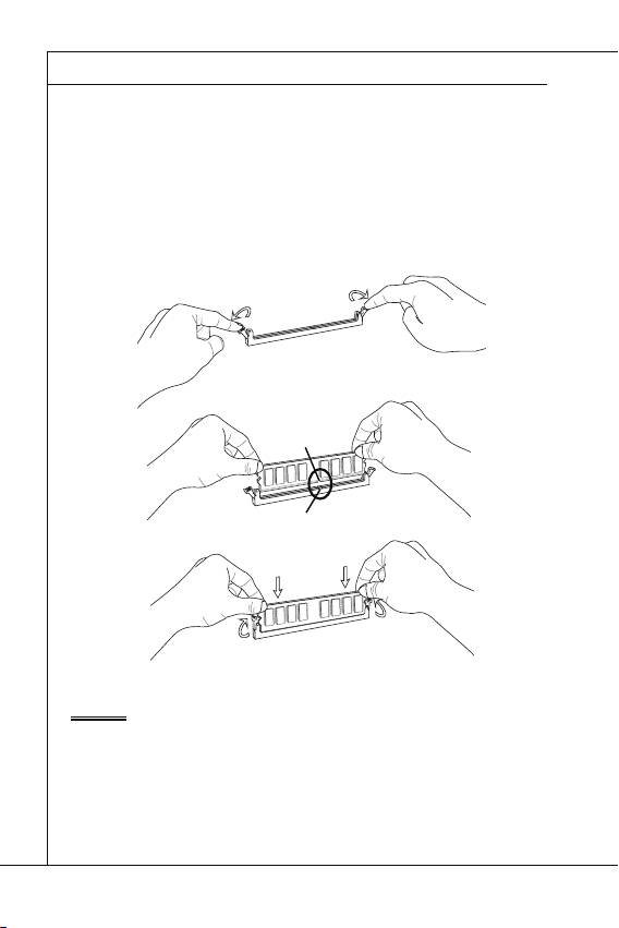
Vorgehensweise beim Einbau von Speicher Modulen
Vorgehensweise beim Einbau von Speicher Modulen
Die Speichermodulen haben nur eine Kerbe in der Mitte des Moduls. Sie passen
nur in einer Richtung in den Sockel.
Stecken Sie das Arbeitsspeichermodul senkrecht in den DIMM-Steckplatz ein.
Drücken Sie anschließnd das Arbeitsspeichermodul nach unten, bis die Kontakt-
seite richtig tief in dem DIMM-Steckplatz sitzt. Der Kunststoff bügel an jedem Ende
des DIMM-Steckplatzes schnappt automatisch ein, wenn das Arbeitsspeichermodul
richtig eingesetzt ist.
Prüfen Sie von Hand, ob das Arbeitsspeichermodul von den seitlichen Bügeln am
DIMM-Steckplatz richtig gehalten wird.
Notch
Kerbe
Wichtig
1.
2.
3.
Wichtig
Die goldenen Kontakte sind kaum zu sehen, wenn das Arbeitsspeichermodul richtig im
DIMM-Steckplatz sitzt.
