Caleffi 638: instruction
Class: Climatic equipment
Type: Radiator
Manual for Caleffi 638

FRANÇAIS DEUTSCH
638
052
DN 20 / 3/4”
230 V
638
054
DN 20 / 3/4”
24 V
638
062
DN 25 / 1”
230 V
638
064
DN 25 / 1”
24 V
638
072
DN 32 / 1 1/4” 230 V
638
074
DN 32 / 1 1/4” 24 V
638
082
DN 50 / 1 1/2” 230 V
638
084
DN 50 / 1 1/2” 24 V
638
092
DN 50 / 2”
230 V
638
094
DN 50 / 2”
24 V
I EN FR DE
ISTRUZIONI PER L’INSTALLAZIONE,
LA MESSA IN SERVIZIO E LA
MANUTENZIONE
Vi ringraziamo per averci preferito nella
scelta di questo prodotto
Ulteriori dettagli tecnici su questo
dispositivo sono disponibili sul sito
www.caleffi.com
VALVOLE A SFERA
MOTORIZZATE PER
CENTRALI TERMICHE
Generalità
Queste serie di valvole a sfera motorizzate sono dotate di
marchi CE secondo le direttive 2006/95/CE e 2004/108/CE.
Avvertenze
Le seguenti istruzioni devono essere lette e comprese prima
dell’installazione e della manutenzione del prodotto. Il
simbolo
significa:
ATTENZIONE! UNA MANCANZA NEL SEGUIRE QUESTE
ISTRUZIONI POTREBBE ORIGINARE PERICOLO!
Sicurezza
É obbligatorio rispettare le istruzioni per la sicurezza
riportate sul documento specifico in confezione.
LASCIARE IL PRESENTE MANUALE AD USO
E SERVIZIO DELL’UTENTE
SMALTIRE IN CONFORMITÀ ALLA NORMATIVA VIGENTE
Funzione
Le valvole motorizzate per centrali termiche permettono
l’intercettazione, la deviazione o la miscelazione automatica del
fluido termovettore.
Caratteristiche tecniche
Materiali
Corpo:
ottone UNI EN 12165 CW617N
Sfera:
ottone UNI EN 12165 CW617N, cromata
Tenuta sfera:
PTFE con O-Ring in EPDM
Tenuta asta comando:
doppio O-Ring in EPDM
Tenuta bocchettoni:
O-Ring in EPDM
Prestazioni
Fluidi di impiego:
acqua, soluzioni glicolate
Max percentuale di glicole:
50%
Pressione massima d’esercizio:
16 bar
Pressione differenziale massima:
10 bar
Passaggio sfera:
passaggio ridotto
Attacchi:
3/4”÷2” M (ISO 7-1) a bocchettone
Attacco inferiore 3 vie:
3/4”÷2” F (ISO 228-1)
Condizioni ambientali (valvola + comando)
Campo di temperatura fluido:
-10÷110°C
Temperatura ambiente:
Funzionamento:
-10÷55°C EN 60721-3-3 Cl. 3K4,
max. umidità 95%
Trasporto:
-30÷70°C EN 60721-3-2 Cl. 2K3,
max. umidità 95%
Stoccaggio:
-20÷70°C EN 60721-3-1 Cl. 1K2,
max. umidità 95%
Caratteristiche tecniche comando
Motore sincrono
Alimentazione:
230 V (ac)
24 V (ac)
Assorbimento:
6 VA
Portata contatti microinterruttore ausiliario:
6 (2) A (230 V)
Grado di protezione:
IP 65
Tempo di manovra: 50 s (rotazione 90°), 100 s (rotazione 180°)
Lunghezza cavo di alimentazione:
0,8 m
Coppia di spunto dinamico:
9 N·m
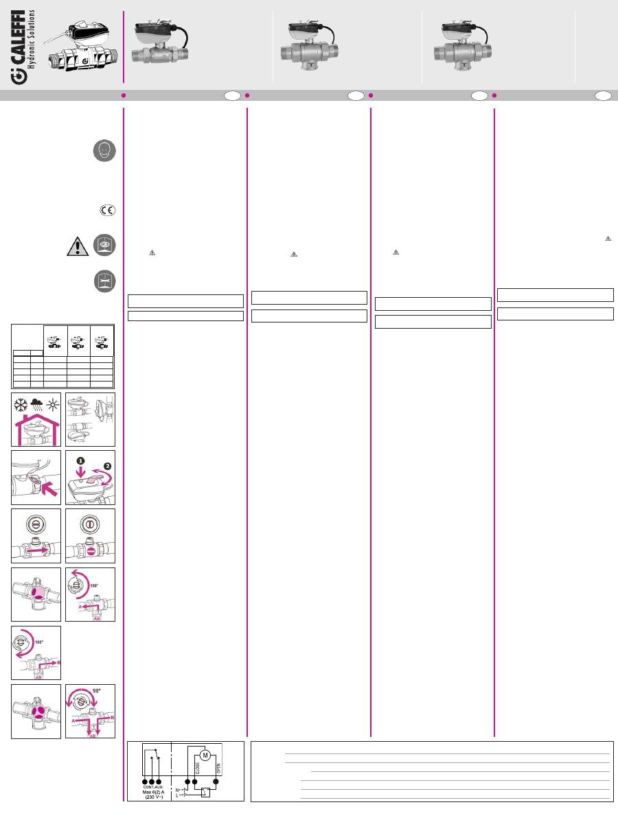
Caratteristiche idrauliche
(fig. A)
*
Corpo valvola
**
Attacchi
Installazione
(fig. B - C - D)
Apertura/chiusura manuale
(fig. E)
Schema di funzionamento valvola a
due vie
(fig. F - G)
Schema di funzionamento valvola a
tre vie
Foratura a
“L”
, utilizzo ON/OFF rotazione di 180° (fig. H - I - L).
Foratura a
“T”
, utilizzo modulante, rotazione di 90° (fig. M - N).
Nota:
la valvola a tre vie, sia quella con foratura a
“L”
sia quella
con foratura a
“T”
, può essere utilizzata in posizione deviatrice
(ingresso comune AB ed uscita A o B) oppure in posizione
miscelatrice (ovvero ingressi in A o B ed uscita comune AB).
Schema elettrico
(fig. O)
Schema interno con valvola in posizione di:
chiusura per valvola a due vie;
chiusura via
A
per valvola a tre vie.
1 = Verde
2 = Bianco
3 = Rosso
4 = Blu
5 = Marrone
6 = Nero
Microinterruttore ausiliario
Il microinterruttore ausiliario è azionato dal movimento di
apertura del servocomando. Il microinterruttore ausiliario si
chiude per un valore medio di apertura del servocomando
dell’95%.
68451
638
053
DN 20 / 3/4”
230 V
638
055
DN 20 / 3/4”
24 V
638
063
DN 25 / 1”
230 V
638
065
DN 25 / 1”
24 V
638
073
DN 32 / 1 1/4” 230 V
638
075
DN 32 / 1 1/4” 24 V
638
083
DN 50 / 1 1/2” 230 V
638
085
DN 50 / 1 1/2” 24 V
638
093
DN 50 / 2”
230 V
638
095
DN 50 / 2”
24 V
© Copyright 2011 Caleffi
www.caleffi.com
D
H
I
M
N
1 2 3
4 5
6
O
B
F
E
C
G
A
DN 20 3/4”
17,00
9,90
9,50
DN 25
1”
36,50
13,40
12,90
DN 32 11/4”
48,00
22,80
24,70
DN 50 11/2”
77,00
44,00
47,00
DN 50
2”
140,00
50,00
50,00
638
638 “L”
638 “T”
Kv
(m
3
/h)
L
NOTE:
NOTES:
REMARQUES :
ANMERKUNGEN:
638
153
DN 20 / 3/4”
230 V
638
155
DN 20 / 3/4”
24 V
638
163
DN 25 / 1”
230 V
638
165
DN 25 / 1”
24 V
638
173
DN 32 / 1 1/4” 230 V
638
175
DN 32 / 1 1/4” 24 V
638
183
DN 50 / 1 1/2” 230 V
638
185
DN 50 / 1 1/2” 24 V
638
193
DN 50 / 2”
230 V
638
195
DN 50 / 2”
24 V
“L”
“T”
* **
INSTRUCTIONS FOR INSTALLATION,
COMMISSIONING AND
MAINTENANCE
Thank you for choosing our product.
Further technical details relating to
this
device
are
available
at
www.caleffi.com
MOTORISED BALL VALVES FOR
CENTRAL HEATING SYSTEMS
General
These series of motorised ball valves carry the CE
marks in accordance with Directives 2006/95/EC and
2004/108/EC.
Warnings
The following instructions must be read and understood
before installing and maintaining the product. The symbol
means:
CAUTION! FAILURE TO FOLLOW THESE INSTRUCTIONS
COULD RESULT IN A SAFETY HAZARD!
Safety
The safety instructions provided in the specific document
supplied MUST be observed.
LEAVE THIS MANUAL AS A REFERENCE GUIDE
FOR THE USER
DISPOSE OF THE PRODUCT IN COMPLIANCE WITH
CURRENT LEGISLATION
Function
The motorised valves for central heating systems can be used
to automatically shut off, divert or mix the thermal medium.
Technical specifications
Materials
Body:
brass EN 12165 CW617N
Ball:
brass EN 12165 CW617N, chrome plated
Ball seal:
PTFE with EPDM O-Ring
Stem seal:
EPDM double O-Ring
Union seal:
EPDM O-Ring
Performance
Medium:
water, glycol solutions
Max. percentage of glycol:
50%
Max. working pressure:
16 bar
Max. differential pressure:
10 bar
Ball passage:
reduced passage
Connections:
3/4”
–
2” M (ISO 7-1) with union
Bottom 3-way connection:
3/4”
–
2” F (ISO 228-1)
Ambient conditions (valve + control)
Medium working temperature range:
-10
–
110°C
Ambient temperature:
Operation:
-10
–
55°C EN 60721-3-3 Cl. 3K4,
max. humidity 95%
Transportation:
-30
–
70°C EN 60721-3-2 Cl. 2K3,
max. humidity 95%
Storage:
-20
–
50°C EN 60721-3-1 Cl. 1K2,
max. humidity 95%
Actuator technical specification
Synchronous motor
Electrical supply:
230 V (ac)
24 V (ac)
Power consumption:
6 VA
Auxiliary microswitch contact rating:
6 (2) A (230 V)
Protection class:
IP 65
Operating time:
50 s (rotation 90°)
Max. ambient temperature:
55°C
Supply cable length:
0,8 m
Dynamic starting torque:
9 N·m
Hydraulic characteristics
(fig. A)
*
Valve body
**
Connections
Installation
(fig. B - C - D)
Manual opening/closing
(fig. E)
Two-way valve operating diagram
(fig. F - G)
Three-way valve operating diagram
"L"
drilling, ON/OFF usage, 180° rotation (fig. H - I - L).
"T"
drilling, modulating usage, 90° rotation (fig. M - N).
Note:
the three-way valve, in both
"L"
and
"T"
drilling versions,
can be used in diverter position (shared inlet AB and outlet A or
B) or in mixing valve position (i.e. inlets in A or B and shared
outlet AB).
Wiring diagram
(fig. O)
Internal diagram with valve in the following position:
closed, for two-way valve;
A
port closed, for three-way valve.
1 = Green
2 = White
3 = Red
4 = Blue
5 = Brown
6 = Black
Auxiliary microswitch
The auxiliary microswitch is activated by the opening movement
of the actuator. The auxiliary microswitch shuts off for an average
actuator opening value of 95%.
CONSIGNES POUR L’INSTALLATION,
LA MISE EN SERVICE
ET L’ENTRETIEN
Merci d’avoir choisi ce produit.
Pour de plus amples informations sur
ce dispositif, veuillez consulter le site
www.caleffi.com
VANNES À SPHÈRE MOTORISÉES
POUR CENTRALES THERMIQUES
Généralités
Ces séries de vannes à sphère motorisées portent le label
CE conformément aux directives 2006/95/CE et
2004/108/CE.
Avertissements
S’assurer d’avoir lu et compris les instructions suivantes
avant de procéder à l’installation et à l’entretien du
dispositif. Le symbole
signifie :
ATTENTION ! LE NON-RESPECT DE CES CONSIGNES
PEUT ENTRAÎNER UNE MISE EN DANGER !
Sécurité
Respecter impérativement les consignes de sécurité
citées sur le document qui accompagne le dispositif.
LAISSER CE MANUEL
AU SERVICE DE L’UTILISATEUR
METTRE AU REBUT CONFORMÉMENT AUX NORMES
EN VIGUEUR
Fonction
Les vannes motorisées pour centrales thermiques permettent
d'arrêter, de dévier ou de mélanger automatiquement le fluide
caloporteur.
Caractéristiques techniques
Matériaux
Corps :
laiton EN 12165 CW617N
Bille :
laiton EN 12165 CW614N, chromée
Sièges sphère :
PTFE avec O’Ring en EPDM
Joint axe de commande :
double O’Ring en EPDM
Joint raccords unions :
O-Ring en EPDM
Performance
Fluide admissible :
eau, solutions glycolées
Pourcentage maxi de glycol :
50%
Pression maxi d'exercice :
16 bar
Pression différentielle maximale :
10 bar
Passage sphère :
passage réduit
Raccordements :
Raccords unions 3/4”÷2” M (ISO 7-1)
Raccord inférieur 3ème voie :
3/4”÷2” F (ISO 228-1)
Conditions ambiantes (vanne + tête)
Plage de température du fluide :
-10÷110°C
Température ambiante :
Fonctionnement:
-10÷55°C EN 60721-3-3 Cl. 3K4,
humidité maxi 95%
Transport :
-30÷70°C EN 60721-3-2 Cl. 2K3,
humidité maxi 95%
Stockage :
-20÷70°C EN 60721-3-1 Cl. 1K2,
humidité maxi 95%
Caractéristiques techniques du moteur
Moteur synchrone
Alimentation :
230 V (~)
24 V (~)
Puissance absorbée :
6 VA
Pouvoir de coupure contact auxiliaire :
6 (2) A (230 V)
Indice de protection :
IP 65
Temps de manœuvre :
50 s (rotation 90°)
Longueur du câble d'alimentation :
0,8 m
Couple de démarrage dynamique :
9 N·m
Caractéristiques hydrauliques
(fig. A)
*
Corps de vanne
**
Raccordements
Installation
(fig. B - C - D)
Ouverture/fermeture manuelle
(fig. E)
Schéma de fonctionnement vanne
deux voies
(fig. F - G)
Schéma de fonctionnement vanne
trois voies
Perçage en
« L »
, utilisation ON/OFF rotation de 180° (fig. H - I - L).
Perçage en
« T »
, utilisation modulante, rotation de 90° (fig. M - N).
Remarque
: la vanne trois voies, qu'elle soit à perçage en
« L
»
ou en
« T »
, peut être utilisée comme vanne déviatrice (entrée
commune AB et sortie A ou B) ou comme vanne mélangeuse
(entrées A et B et sortie commune AB).
Schéma électrique
(fig. O)
Schéma interne avec vanne en position de :
fermeture pour vanne deux voies;
fermeture voie
A
pour vanne trois voies.
1 = Vert
2 = Blanc
3 = Rouge
4 = Bleu
5 = Marron
6 = Noir
Contact auxiliaire
Le contact auxiliaire est actionné par le mouvement d'ouverture
du servomoteur. Le contact auxiliaire se ferme à une valeur
moyenne d'ouverture du servomoteur de 95%.
INSTALLATIONS-,
INBETRIEBNAHME- UND
WARTUNGSANWEISUNGEN
Wir bedanken uns, dass Sie sich für
unser Produkt entschieden haben.
Weitere technische Details zu diesem
Gerät finden Sie unter www.caleffi.com
MOTOR-KUGELVENTILE FÜR
WÄRMEZENTRALEN
Allgemeines
Diese Serie von Motor-Kugelventilen verfügt über die
CE-Kennzeichnung gemäß den Richtlinien 2006/95/EG und
2004/108/EG.
Hinweis
Die folgenden Anweisungen müssen vor Installation und
Wartung des Gerätes gelesen und verstanden worden sein.
Das Symbol
bedeutet:
ACHTUNG! EINE MISSACHTUNG DIESER ANWEISUNGEN
KANN GEFAHRENSITUATIONEN VERURSACHEN!
Sicherheit
Die in der beigelegten Dokumentation enthaltenen
Sicherheitsanweisungen müssen beachtet werden.
DIESE ANLEITUNG IST DEM
BENUTZER AUSZUHÄNDIGEN
DEN GELTENDEN VORSCHRIFTEN ENTSPRECHEND
ENTSORGEN
Funktion
Die Motorventile für Wärmezentralen ermöglichen das
Absperren, Umschalten oder das automatische Mischen des
Mediums.
Technische Eigenschaften
Materialien
Gehäuse:
Messing EN 12165 CW617N
Kugel:
Messing EN 12165 CW617N, verchromt
Kugeldichtung:
PTFE mit O-Ring aus EPDM
Steuerspindeldichtung:
doppelter O-Ring aus EPDM
Verschraubungsdichtung:
O-Ring aus EPDM
Leistungen
Betriebsmedien:
Wasser, Glykollösungen
Maximaler Glykolgehalt:
50%
Max. Betriebsdruck:
16 bar
Maximaler Differenzdruck:
10 bar
Kugeldurchgang:
reduzierter Durchgang
Anschlüsse:
3/4”÷2” M (ISO 7-1) mit Verschraubung
Unterer 3-Wege-Anschluss:
3/4”÷2” IG (ISO 228-1)
Arbeitsbereich - Ventil und Antrieb
Temperaturbereich des Mediums:
-10÷110°C
Umgebungstemperatur:
Betrieb:
-10÷55°C EN 60721-3-3 Kl. 3K4,
max. Feuchtigkeit 95%
Transport:
-30÷70°C EN 60721-3-2 Kl. 2K3,
max. Feuchtigkeit 95%
Lagerung:
-20÷70°C EN 60721-3-1 Kl. 1K2,
max. Feuchtigkeit 95%
Technische Eigenschaften Wärmedämmschale
Synchronmotor
Betriebsspannung:
230 V (ac)
24 V (ac)
Leistungsaufnahme:
6 VA
Stromaufnahme des Hilfsschalters:
6 (2) A (230 V)
Schutzart:
IP 65
Schaltzeit:
50 s (90°-Drehung)
Kabellänge:
0,8 m
Dynamisches Anlaufmoment:
9 N·m
Hydraulische Eigenschaften
(Abb. A)
*
Ventilkörper
**
Anschlüsse
Installation
(Abb. B - C - D)
Manuelles Öffnen/Schließen
(Abb. E)
Funktionsschema Zweiwegeventil
(Abb. F - G)
Funktionsschema Dreiwegeventil
“L”
-Bohrung, ON/OFF-Betrieb, 180°-Drehung (Abb. H - I - L).
“T”
-Bohrung, modulierender Betrieb, 90°-Drehung (Abb. M - N).
Hinweis:
Das Dreiwegeventil, sowohl mit
“L”
- Bohrung als
auch mit
“T”
-Bohrung, kann in Umschaltstellung (gemeinsamer
Eingang AB und Ausgang A oder B) oder in Mischstellung (d. h.
Eingänge in A oder B und gemeinsamer Ausgang AB)
verwendet werden.
Schaltplan
(Abb. O)
Innenschema mit Ventil in Stellung:
Schließen für Zweiwegeventil;
Schließen Weg
A
für Dreiwegeventil.
1 = Grün
2 = Weiß
3 = Rot
4 = Blau
5 = Braun
6 = Schwarz
Hilfsschalter
Der Hilfsschalter wird durch die Öffnungsbewegung des
Stellantriebs betätigt. Der Hilfsschalter schließt bei einem
mittleren Öffnungswert des Stellantriebs von 95%.
ENGLISH ITALIANO
PORTUGUÊS NEDERLANDS RUSSO PT NL RU ESPAÑOL ES
NOTAS:
NOTAS:
OPMERKINGEN:
ПРИМЕЧАНИЯ:
© Copyright 2011 Caleffi
www.caleffi.com
D
H
I
M
N
1 2 3
4 5
6
B
F
E
C
G
A
DN 20 3/4”
17,00
9,90
9,50
DN 25
1”
36,50
13,40
12,90
DN 32 11/4”
48,00
22,80
24,70
DN 50 11/2”
77,00
44,00
47,00
DN 50
2”
140,00
50,00
50,00
638
638 “L”
638 “T”
Kv
(m
3
/h)
L
* **
638
052
DN 20 / 3/4”
230 V
638
054
DN 20 / 3/4”
24 V
638
062
DN 25 / 1”
230 V
638
064
DN 25 / 1”
24 V
638
072
DN 32 / 1 1/4” 230 V
638
074
DN 32 / 1 1/4” 24 V
638
082
DN 50 / 1 1/2” 230 V
638
084
DN 50 / 1 1/2” 24 V
638
092
DN 50 / 2”
230 V
638
094
DN 50 / 2”
24 V
638
053
DN 20 / 3/4”
230 V
638
055
DN 20 / 3/4”
24 V
638
063
DN 25 / 1”
230 V
638
065
DN 25 / 1”
24 V
638
073
DN 32 / 1 1/4” 230 V
638
075
DN 32 / 1 1/4” 24 V
638
083
DN 50 / 1 1/2” 230 V
638
085
DN 50 / 1 1/2” 24 V
638
093
DN 50 / 2”
230 V
638
095
DN 50 / 2”
24 V
638
153
DN 20 / 3/4”
230 V
638
155
DN 20 / 3/4”
24 V
638
163
DN 25 / 1”
230 V
638
165
DN 25 / 1”
24 V
638
173
DN 32 / 1 1/4” 230 V
638
175
DN 32 / 1 1/4” 24 V
638
183
DN 50 / 1 1/2” 230 V
638
185
DN 50 / 1 1/2” 24 V
638
193
DN 50 / 2”
230 V
638
195
DN 50 / 2”
24 V
“L”
“T”
INSTRUÇÕES PARA A INSTALAÇÃO,
COLOCAÇÃO EM SERVIÇO E
MANUTENÇÃO
Agradecemos
a
preferência
na
selecção deste produto.
Dados técnicos adicionais sobre este
dispositivo encontram-se disponíveis
no site www.caleffi.com.
VÁLVULAS DE ESFERA
MOTORIZADAS PARA CENTRAIS
TÉRMICAS
Generalidades
Esta série de válvulas de esfera motorizadas possui a
marca CE segundo as das directivas 2006/95/CE e
2004/108/CE.
Advertências
As instruções que se seguem devem ser lidas e
compreendidas antes da instalação e da manutenção do
produto. O símbolo
significa:
ATENÇÃO! O INCUMPRIMENTO DESTAS INSTRUÇÕES
PODERÁ ORIGINAR PERIGO!
Segurança
É obrigatório respeitar as instruções de segurança
indicadas no documento específico contido na embalagem.
DEIXAR O PRESENTE MANUAL
À DISPOSIÇÃO DO UTILIZADOR
ELIMINAR EM CONFORMIDADE
COM AS NORMAS EM VIGOR
Função
As válvulas motorizadas para centrais térmicas permitem a
intercepção, o desvio ou a mistura automática do fluido
termovector.
Características técnicas
Materiais
Corpo:
latão UNI EN 12165 CW617N
Esfera:
latão UNI EN 12165 CW617N, cromada
Vedação da esfera:
PTFE com O-Ring em EPDM
Vedação haste de comando:
duplo O-Ring em EPDM
Vedação dos casquilhos:
O-Ring em EPDM
Desempenho
Fluidos de utilização:
água, soluções com glicol
Percentagem máx. de glicol:
50%
Pressão máxima de exercício:
16 bar
Pressão diferencial máxima:
10 bar
Passagem da esfera:
passagem reduzida
Ligações:
3/4”÷2” M (ISO 7-1) com casquilho
Ligação inferior 3 vias:
3/4”÷2” F (ISO 228-1)
Condições ambientais (válvula + comando)
Campo de temperatura fluido:
-10÷110°C
Temperatura ambiente:
Funcionamento:
-10÷55°C EN 60721-3-3 Cl. 3K4,
humidade máx. 95%
Transporte:
-30÷70°C EN 60721-3-2 Cl. 2K3,
humidade máx. 95%
Armazenamento:
-20÷70°C EN 60721-3-1 Cl. 1K2,
humidade máx. 95%
Características técnicas comando
Motor síncrono
Alimentação:
230 V (ac)
24 V (ac)
Consumo:
6 VA
Corrente contactos micro-interruptor auxiliar:
6 (2) A (230 V)
Grau de protecção:
IP 65
Tempo de manobra:
50 s (rotação 90°)
Comprimento do cabo de alimentação:
0,8 m
Binário de arranque dinâmico:
9 N·m
Características hidráulicas
(fig. A)
*
Corpo da válvula
**
Ligações
Instalação
(fig. B - C - D)
Abertura/fecho manual
(fig. E)
Esquema
de
funcionamento
da
válvula de duas vias
(fig. F - G)
Esquema
de
funcionamento
da
válvula de três vias
Furação em
“L”
, utilização ON/OFF rotação de 180° (fig. H - I - L).
Furação em
“T”
, utilização modulante, rotação de 90° (fig. M - N).
Nota:
: a válvula de três vias, quer com furação em
“L”
quer
com furação em
“T”
, pode ser utilizada na posição de desvio
(entrada comum AB e saída A ou B) ou na posição de mistura
(ou seja, entradas em A ou B e saída comum AB).
Esquema eléctrico
(fig. O)
Esquema interno com válvula na posição de:
fecho para válvula de duas vias;
fecho da via
A
para válvula de três vias.
1 = Verde
2 = Branco
3 = Vermelho
4 = Azul
5 = Castanho 6 = Preto
Micro-interruptor auxiliar
O micro-interruptor auxiliar é accionado pelo movimento
de abertura do comando electrotérmico. O micro-
interruptor auxiliar fecha-se no caso de um valor médio
de abertura do servocomando de 95%.
AANWIJZINGEN VOOR INSTALLATIE,
INBEDRIJFSTELLING EN
ONDERHOUD
We bedanken U voor de keuze van een
van onze producten.
Nadere technische details omtrent dit
systeem vindt U op onze site
www.caleffi.com
GEMOTORISEERDE VENTIELEN
MET KOGELAFSLUITER VOOR
VERWARMINGSSYSTEMEN
Algemeen
Deze serie gemotoriseerde ventielen met kogelafsluiter is
voorzien van het CE keurmerk in overeenstemming met de
richtlijnen 2006/95/EG en 2004/108/EG.
Waarschuwingen
De navolgende aanwijzingen aandachtig doorlezen alvorens
het product te installeren en onderhoud te verrichten. Het
symbool
betekent:
LET OP! NIET NAVOLGEN VAN DEZE AANWIJZINGEN
KAN GEVAARLIJK ZIJN!
Veiligheid
Het is verplicht de veiligheidsvoorschriften op te volgen die
vermeld staan op het specifieke document in de verpakking.
DE HANDLEIDING DIENT ALS NASLAGWERK
VOOR DE GEBRUIKER
HET PRODUCT VERWIJDEREN IN OVEREENSTEMMING
MET DE GELDENDE WETGEVING
Functie
De gemotoriseerde ventielen voor verwarmingssystemen zijn
bestemd voor het afsluiten, omleiden of automatisch mengen
van de warmtegeleidende vloeistof.
Technische gegevens
Materialen
Lichaam:
messing EN 12165 CW617N
Kogel:
messing EN 12165 CW617N. Verchroomd
Kogelafdichting
PTFE met O-ring in EPDM
Dichting regelstang:
dubbele O-ring in EPDM
Dichting wartels:
O-ring in EPDM
Prestaties
Vloeistof:
water, glycoloplossingen
Max. glycolpercentage:
50%
Max. werkingsdruk:
16 bar
Maximaal drukverschil:
10 bar
Kogeldoorlaat:
gereduceerde doorlaat
Aansluitingen:
3/4”÷2” M (ISO 7-1) met wartel
Onderste driewegaansluiting:
3/4”÷2” F (ISO 228-1)
Omgevingscondities (ventiel + bediening)
Temperatuurbereik vloeistof:
-10 tot 110°C
Omgevingstemperatuur:
Werking:
-10 tot 55°C EN 60721-3-3 Cl. 3K4,
max. vochtigheid 95%
Transport:
-30 tot 70°C EN 60721-3-2 Cl. 2K3,
max. vochtigheid 95%
Opslag:
-20 tot 70°C EN 60721-3-1 Cl. 1K2,
max. vochtigheid 95%
Technische gegevens aandrijving
Synchroonmotor
Voeding:
230 V (ac)
24 V (ac)
Opgenomen vermogen:
6 VA
Capaciteit extra microschakelaar:
6 (2) A (230 V)
Beschermingsgraad:
IP 65
Schakeltijd:
50 s (rotatie 90°)
Kabel:
0,8 m
Dynamisch koppel:
9 N·m
Hydraulische gegevens
(fig. A)
* Ventiellichaam
** Aansluitingen
Installatie
(fig. B - C - D)
Handmatig openen/sluiten
(fig. E)
Werkingsschema tweewegventiel
(fig. F - G)
Werkingsschema driewegventiel
Doorlaat
“L”
, ON/OFF-gebruik, rotatie 180° (fig. H - I - L).
Doorlaat
“T”
, modulerend gebruik, rotatie 90° (fig. M - N).
Opmerking:
Opmerking: het driewegventiel kan zowel in de
uitvoering met doorlaat
“L”
als met doorlaat
“T”
worden
gebruikt in de verdeelstand (gemeenschappelijke ingang AB en
uitgang A of B), of in de mengstand (d.w.z. ingangen in A of B
en gemeenschappelijke uitgang AB).
Schakelschema
(fig. O)
Intern schema met ventiel in gesloten stand:
sluiting voor tweewegventiel;
sluiting weg
A
voor driewegventiel.
1 = Groen
2 = Wit
3 = Rood
4 = Blauw
5 = Bruin
6 = Zwart
Extra microschakelaar
De extra microschakelaar wordt ingeschakeld door de
openingsbeweging van de servomotor. De extra
microschakelaar
sluit
zich
bij
een
gemiddelde
openingswaarde van de servomotor van 95%.
INSTRUCCIONES DE INSTALACIÓN,
PUESTA EN MARCHA Y
MANTENIMIENTO
Gracias por escoger un producto de
nuestra marca.
Encontrará más información sobre
este
dispositivo
en
la
página
www.caleffi.com.
VÁLVULAS DE ESFERA
MOTORIZADAS PARA
CENTRALES TÉRMICAS
Generalidades
Las válvulas de esfera motorizadas de esta serie llevan el
marcado CE de acuerdo con las directivas 2006/95/CE y
2004/108/CE.
Advertencias
Estas instrucciones deben leerse y comprenderse antes de
realizar la instalación y el mantenimiento del producto.
El símbolo
significa:
¡ATENCIÓN!
EL
INCUMPLIMIENTO
DE
ESTAS
INSTRUCCIONES PUEDE SER PELIGROSO.
Seguridad
Es obligatorio respetar las instrucciones de seguridad
indicadas en el documento específico que se entrega con
el producto.
ENTREGAR ESTE MANUAL
AL USUARIO
DESECHAR SEGÚN LA NORMATIVA LOCAL
Función
Las válvulas motorizadas para centrales térmicas permiten
interceptar, desviar y mezclar de forma automática el fluido
caloportador.
Características técnicas
Materiales
Cuerpo:
latón EN 12165 CW617N
Esfera:
latón EN 12165 CW614N, cromada
Sello de la esfera:
PTFE con junta tórica de EPDM
Sello del eje:
dos juntas tóricas de EPDM
Sello de los racores:
juntas tóricas de EPDM
Prestaciones
Fluido utilizable:
agua o soluciones de glicol
Porcentaje máximo de glicol:
50%
Presión máxima de servicio:
16 bar
Presión diferencial máxima:
10 bar
Paso esfera:
paso reducido
Conexiones:
3/4”÷2” M (ISO 7-1) con enlace
Conexión inferior 3 vías:
3/4”÷2” H (ISO 228-1)
Condiciones ambientales (válvula y mando)
Campo de temperatura del fluido:
-10÷110°C
Temperatura ambiente:
Funcionamiento:
-10÷55°C EN 60721-3-3 Cl. 3K4,
hum. máx. 95%
Transporte:
-30÷70°C EN 60721-3-2 Cl. 2K3,
hum. máx. 95%
Almacenamiento:
-20÷70°C EN 60721-3-1 Cl. 1K2,
hum. máx. 95%
Características técnicas del mando
Motor síncrono
Alimentación eléctrica:
230 V (ac)
24 V (ac)
Potencia absorbida:
6 VA
Capacidad contactos microinterruptor auxiliar:
6 (2) A (230 V)
Grado de protección:
IP 65
Tiempo de maniobra:
50 s (rotación 90°)
Longitud del cable de alimentación:
0,8 m
Par de arranque dinámico:
9 N·m
Características hidráulicas
(fig. A)
*
Cuerpo de la válvula
**
Conexiones
Instalación
(fig. B - C - D)
Apertura/cierre manual
(fig. E)
Esquema de funcionamiento de la
válvula de dos vías
(fig. F - G)
Esquema de funcionamiento de la
válvula de tres vías
Orificios en
“L”
, uso ON/OFF, rotación 180° (figs. H - I - L).
Orificios en
“T”
, uso modulante, rotación 90° (figs. M - N).
Nota:
Nota: la válvula de tres vías, tanto con orificios en
“L”
como en
“T”
, puede emplearse en posición desviadora
(entrada común AB y salidas A o B) o en posición mezcladora
(entradas A o B y salida común AB).
Esquema eléctrico
(fig. O)
Esquema interno con válvula en posición de:
cierre para válvula de dos vías;
cierre de la vía
A
para válvula de tres vías.
1 = Verde
2 = Blanco
3 = Rojo
4 = Azul
5 = Marrón
6 = Negro
Microinterruptor auxiliar
El microinterruptor auxiliar se acciona con el movimiento
de apertura del servomando. El microinterruptor auxiliar
se
cierra
cuando
el
servomando
se
abre
aproximadamente al 95%.
ИНСТРУКЦИИ ПО УСТАНОВКЕ,
ПУСКУ В ЭКСПЛУАТАЦИЮ И
ТЕХОБСЛУЖИВАНИЮ
Благодарим Вас за выбор нашего
изделия.
За
дополнительной
технической
информацией по данному устройству
обращайтесь
к
Интернет-сайту
www.caleffi.com.
ШАРОВЫЕ КЛАПАНЫ С
ЭЛЕКТРОПРИВОДОМ
ДЛЯ ТЕПЛОВЫХ ПУНКТОВ
Общие сведения
Эти шаровые клапаны с электроприводом имеют маркировку
CE в соответствии с директивами 2006/95/CE и 2004/108/CE.
Предупреждения
Данные инструкции должны быть прочитаны и усвоены до
начала монтажа и техобслуживания изделия. Символ
означает:
ВНИМАНИЕ! НЕСОБЛЮДЕНИЕ ДАННЫХ ИНСТРУКЦИЙ МОЖЕТ
ПРИВЕСТИ К СОЗДАНИЮ ОПАСНЫХ СИТУАЦИЙ!
Безопасность
Обязательно соблюдайте инструкции по безопасности,
приведенные в специальном документе, входящем в
упаковку.
ДАННЫЕ ИНСТРУКЦИИ ДОЛЖНЫ НАХОДИТЬСЯ
В РАСПОРЯЖЕНИИ ПОЛЬЗОВАТЕЛЯ
УТИЛИЗАЦИЯ ДОЛЖНА ПРОВОДИТЬСЯ СОГЛАСНО
ДЕЙСТВУЮЩИМ НОРМАТИВАМ
Функциональное назначение
Клапаны с электроприводом для тепловых станций позволяют
автоматически осуществлять отсечение, отклонение и
смешивание теплоносителя.
Технические характеристики
Материалы
Корпус:
латунь EN 12165 CW617N
Шар:
латунь EN 12165 CW617N, хромированная
Уплотнение шара:
тефлон (PTFE) с уплотнительным
кольцом из каучука EPDM
Уплотнение штока:
двойное уплотнительное кольцо
из каучука EPDM
Уплотнение патрубков: уплотнительное кольцо из каучука EPDM
Эксплуатационные характеристики
Рабочая среда:
вода, этиленгликолевые растворы
Максимальное процентное содержание этиленгликоля: 50%
Максимальное рабочее давление:
16 бар
Максимальное дифференциальное давление:
10 бар
Проходимость шара:
редуцированный проход
Соединения:
патрубки с наружной резьбой 3/4”÷2” (ISO 7-1)
Нижний тройник:
3/4”÷2” (ISO 228-1) с внутренней резьбой
Условия окружающей среды (клапан + привод)
Диапазон температуры жидкости:
-10÷110°C
Температура окружающей среды:
Функционирование:
-10÷55°C EN 60721-3-3 Cl. 3K4,
макс. влажность 95%
Транспортировка:
-30÷70°C EN 60721-3-2 Cl. 2K3,
макс. влажность 95%
Хранение:
-20÷70°C EN 60721-3-1 Cl. 1K2,
макс. влажность 95%
Технические характеристики привода
Синхронный двигатель
Электропитание:
230 В (переменное напряжение)
24 В (переменное напряжение)
Потребляемая мощность:
6 ВА
Ёмкость контактов вспомогательного
микропереключателя:
6 (2) A (230 В)
Класс защиты:
IP 65
Время срабатывания:
50 с (поворот на 90°)
Длина кабеля питания:
0,8 м
Динамический пусковой момент:
9 Н·м
Гидравлические характеристики
(рис. A)
*
Корпус клапана
**
Соединения
Монтаж
(рис. B - C - D)
Ручное открывание/закрывание
(рис. E)
Схема функционирования двухходового
клапана
(рис. F - G)
Схема функционирования трехходового
клапана
L-образное отверстие, использование в режиме ON/OFF,
поворот на 180° (рис. H - I - L).
T-образное
отверстие,
использование
для
плавного
управления, поворот на 90° (рис. M - N).
Примечание: трехходовой клапан, как с L-образным, так и с T-
образным отверстием может использоваться в режиме
перекидного клапана (общий вход AB и выход A или B) или
смесителя (вход A или B и общий выход AB).
Электрическая схема
(рис. O)
Внутренняя схема при:
двухходовом клапане в закрытом положении;
трехходовом клапане с закрытым портом
А
.
1 = зеленый
2 = белый
3 = красный
4 = синий
5 = коричневый
6 = черный
Вспомогательный микропереключатель
Вспомогательный
микропереключатель
приводится
в
действие за счет движения (открытия) сервопривода.
Контакты вспомогательного микропереключателя замыкаются
при среднем значении открытия сервопривода, равном 95%.
O
