Shure BLX4R: instruction
Class: Audio Accessories
Type:
Manual for Shure BLX4R
BLX4R Wireless Receiver
Récepteur sans fil BLX4R
BLX4R Drahtlosempfänger
Receptor inalámbrico BLX4R
Radioricevitore BLX4R
Беспроводной приемник BLX4R
BLX4R draadloze ontvanger
©2013 Shure Incorporated
Printed in U.S.A.
27A21196 (Rev. 3)

IMPORTANT SAFETY INSTRUCTIONS
14. REFER all servicing to qualified service personnel. Servicing is required when the ap-
paratus has been damaged in any way, such as power supply cord or plug is damaged,
1. READ these instructions.
liquid has been spilled or objects have fallen into the apparatus, the apparatus has been
2. KEEP these instructions.
exposed to rain or moisture, does not operate normally, or has been dropped.
3. HEED all warnings.
15. DO NOT expose the apparatus to dripping and splashing. DO NOT put objects filled with
4. FOLLOW all instructions.
liquids, such as vases, on the apparatus.
5. DO NOT use this apparatus near water.
16. The MAINS plug or an appliance coupler shall remain readily operable.
6. CLEAN ONLY with dry cloth.
17. The airborne noise of the Apparatus does not exceed 70dB (A).
7. DO NOT block any ventilation openings. Allow sufficient distances for adequate ventila-
18. Apparatus with CLASS I construction shall be connected to a MAINS socket outlet with a
tion and install in accordance with the manufacturer’s instructions.
protective earthing connection.
8. DO NOT install near any heat sources such as open flames, radiators, heat registers,
19. To reduce the risk of fire or electric shock, do not expose this apparatus to rain or
stoves, or other apparatus (including amplifiers) that produce heat. Do not place any open
moisture.
flame sources on the product.
20. Do not attempt to modify this product. Doing so could result in personal injury and/or
9. DO NOT defeat the safety purpose of the polarized or groundingtype plug. A polarized
product failure.
plug has two blades with one wider than the other. A grounding type plug has two blades
21. Operate this product within its specified operating temperature range.
and a third grounding prong. The wider blade or the third prong are provided for your
safety. If the provided plug does not fit into your outlet, consult an electrician for replace-
This symbol indicates that dangerous voltage constituting a risk of
ment of the obsolete outlet.
electric shock is present within this unit.
10. PROTECT the power cord from being walked on or pinched, particularly at plugs, conve-
nience receptacles, and the point where they exit from the apparatus.
11. ONLY USE attachments/accessories specified by the manufacturer.
This symbol indicates that there are important operating and mainte-
12. USE only with a cart, stand, tripod, bracket, or table specified by the manu-
nance instructions in the literature accompanying this unit.
facturer, or sold with the apparatus. When a cart is used, use caution when
moving the cart/apparatus combination to avoid injury from tip-over.
13. UNPLUG this apparatus during lightning storms or when unused for long
WARNING: This product contains a chemical known to the State of California to cause cancer and birth
defects or other reproductive harm.
periods of time.
CONSIGNES DE SÉCURITÉ IMPORTANTES
13. DÉBRANCHER l'appareil pendant les orages ou quand il ne sera pas utilisé pendant
longtemps.
1. LIRE ces consignes.
14. CONFIER toute réparation à du personnel qualifié. Des réparations sont nécessaires
2. CONSERVER ces consignes.
si l'appareil est endommagé d'une façon quelconque, par exemple : cordon ou prise
3. OBSERVER tous les avertissements.
d'alimentation endommagé, liquide renversé ou objet tombé à l'intérieur de l'appareil,
4. SUIVRE toutes les consignes.
exposition de l'appareil à la pluie ou à l'humidité, appareil qui ne marche pas normale-
5. NE PAS utiliser cet appareil à proximité de l'eau.
ment ou que l'on a fait tomber.
6. NETTOYER UNIQUEMENT avec un chiffon sec.
15. NE PAS exposer cet appareil aux égouttures et aux éclaboussements. NE PAS poser
7. NE PAS obstruer les ouvertures de ventilation. Laisser des distances suffisantes pour
des objets contenant de l'eau, comme des vases, sur l'appareil.
permettre une ventilation adéquate et effectuer l'installation en respectant les instructions
16. La prise SECTEUR ou un coupleur d’appareil électrique doit rester facilement utilisable.
du fabricant.
17. Le bruit aérien de l'appareil ne dépasse pas 70 dB (A).
8. NE PAS installer à proximité d'une source de chaleur telle qu'une flamme nue, un
18. L'appareil de construction de CLASSE I doit être raccordé à une prise SECTEUR dotée
radiateur, une bouche de chaleur, un poêle ou d'autres appareils (dont les amplificateurs)
d'une protection par mise à la terre.
produisant de la chaleur. Ne placer aucune source à flamme nue sur le produit.
19. Pour réduire les risques d'incendie ou de choc électrique, ne pas exposer cet appareil à
9. NE PAS détériorer la sécurité de la fiche polarisée ou de la fiche de terre. Une fiche
la pluie ou à l'humidité.
polarisée comporte deux lames dont l'une est plus large que l'autre. Une fiche de terre
20. Ne pas essayer de modifier ce produit. Cela risque de causer des blessures et/ou la
comporte deux lames et une troisième broche de mise à la terre. La lame la plus large ou
défaillance du produit.
la troisième broche assure la sécurité de l'utilisateur. Si la fiche fournie ne s'adapte pas à
21. Utiliser ce produit dans sa plage de températures de fonctionnement spécifiée.
la prise électrique, demander à un électricien de remplacer la prise hors normes.
10. PROTÉGER le cordon d'alimentation afin que personne ne marche dessus et que rien ne
Ce symbole indique la présence d'une tension dangereuse dans
le pince, en particulier au niveau des fiches, des prises de courant et du point de sortie
l'appareil constituant un risque de choc électrique.
de l'appareil.
11. UTILISER UNIQUEMENT les accessoires spécifiés par le fabricant.
12. UTILISER uniquement avec un chariot, un pied, un trépied, un support ou
Ce symbole indique que la documentation fournie avec l'appareil con-
une table spécifié par le fabricant ou vendu avec l'appareil. Si un chariot
tient des instructions d'utilisation et d'entretien importantes.
est utilisé, déplacer l'ensemble chariot-appareil avec précaution afin de ne
pas le renverser, ce qui pourrait entraîner des blessures.
WICHTIGE SICHERHEITSHINWEISE
14. ALLE Reparatur- und Wartungsarbeiten von qualifiziertem Kundendienstpersonal
durchführen lassen. Kundendienst ist erforderlich, wenn das Gerät auf irgendwelche
1. Diese Hinweise LESEN.
Weise beschädigt wurde, z. B. wenn das Netzkabel oder der Netzstecker beschädigt
2. Diese Hinweise AUFBEWAHREN.
wurden, wenn Flüssigkeiten in das Gerät verschüttet wurden oder Fremdkörper
3. Alle Warnungen BEACHTEN.
hineinfielen, wenn das Gerät Regen oder Feuchtigkeit ausgesetzt war, nicht normal
4. Alle Hinweise BEFOLGEN.
funktioniert oder fallen gelassen wurde.
5. Dieses Gerät NICHT in Wassernähe VERWENDEN.
15. Dieses Gerät vor Tropf- und Spritzwasser SCHÜTZEN. KEINE mit Wasser gefüllten
6. NUR mit einem sauberen Tuch REINIGEN.
Gegenstände wie zum Beispiel Vasen auf das Gerät STELLEN.
7. KEINE Lüftungsöffnungen verdecken. Hinreichende Abstände für ausreichende Belüftung
16. Der Netzstecker oder eine Gerätesteckverbindung muss leicht zu betätigen sein.
vorsehen und gemäß den Anweisungen des Herstellers installieren.
17. Der Luftschall des Geräts überschreitet 70 dB (A) nicht.
8. NICHT in der Nähe von Wärmequellen wie zum Beispiel offenen Flammen, Heizkörpern,
18. Das Gerät mit Bauweise der KLASSE I muss mit einem Schukostecker mit Schutzleiter in
Wärmespeichern, Öfen oder anderen Hitze erzeugenden Geräten (einschließlich
eine Netzsteckdose mit Schutzleiter eingesteckt werden.
Verstärkern) installieren. Keine Quellen von offenen Flammen auf dem Produkt platzieren.
19. Dieses Gerät darf nicht Regen oder Feuchtigkeit ausgesetzt werden, um das Risiko von
9. Die Schutzfunktion des Schukosteckers NICHT umgehen. Ein Schukostecker verfügt
Bränden oder Stromschlägen zu verringern.
über zwei Steckerzinken sowie Schutzleiter. Bei dieser Steckerausführung dienen die
20. Nicht versuchen, dieses Produkt zu modifizieren. Ansonsten könnte es zu Verletzungen
Schutzleiter Ihrer Sicherheit. Wenn der mitgelieferte Stecker nicht in die Steckdose passt,
und/oder zum Produktausfall kommen.
einen Elektriker mit dem Austauschen der veralteten Steckdose beauftragen.
21. Dieses Produkt muss innerhalb des vorgeschriebenen Temperaturbereichs betrieben
10. VERHINDERN, dass das Netzkabel gequetscht oder darauf getreten wird, insbesondere
werden.
im Bereich der Stecker, Netzsteckdosen und an der Austrittsstelle vom Gerät.
11. NUR das vom Hersteller angegebene Zubehör und entsprechende Zusatzgeräte
Dieses Symbol zeigt an, dass gefährliche Spannungswerte, die ein
verwenden.
Stromschlagrisiko darstellen, innerhalb dieses Geräts auftreten.
12. NUR in Verbindung mit einem vom Hersteller angegebenen oder mit dem Gerät
verkauften Transportwagen, Stand, Stativ, Träger oder Tisch verwenden. Wenn ein
Dieses Symbol zeigt an, dass das diesem Gerät beiliegende Handbuch
Transportwagen verwendet wird, beim Verschieben der Transportwagen/Geräte-Einheit
wichtige Betriebs- und Wartungsanweisungen enthält.
vorsichtig vorgehen, um Verletzungen durch Umkippen zu verhüten.
13. Bei Gewitter oder wenn das Gerät lange Zeit nicht benutzt wird, das Netzkabel
HERAUSZIEHEN.
INSTRUCCIONES IMPORTANTES DE SEGURIDAD
13. DESENCHUFE el aparato durante las tormentas eléctricas, o si no va a ser utilizado por
un lapso prolongado.
1. LEA estas instrucciones.
14. TODA reparación debe ser llevada a cabo por técnicos calificados. El aparato requiere
2. CONSERVE estas instrucciones.
reparación si ha sufrido cualquier tipo de daño, incluyendo los daños al cordón o enchufe
3. PRESTE ATENCION a todas las advertencias.
eléctrico, si se derrama líquido sobre el aparato o si caen objetos en su interior, si ha sido
4. SIGA todas las instrucciones.
expuesto a la lluvia o la humedad, si no funciona de modo normal, o si se ha caído.
5. NO utilice este aparato cerca del agua.
15. NO exponga este aparato a chorros o salpicaduras de líquidos. NO coloque objetos
6. LIMPIE UNICAMENTE con un trapo seco.
llenos con líquido, tales como floreros, sobre el aparato.
7. NO obstruya ninguna de las aberturas de ventilación. Deje espacio suficiente para
16. El enchufe de alimentación o un acoplador para otros aparatos deberá permanecer en
proporcionar ventilación adecuada e instale los equipos según las instrucciones del
buenas condiciones de funcionamiento.
fabricante.
17. El nivel de ruido transmitido por el aire del aparato no excede de 70 dB(A).
8. NO instale el aparato cerca de fuentes de calor tales como llamas descubiertas, radiad-
18. Los aparatos de fabricación CLASE I deberán conectarse a un tomacorriente de ALI-
ores, registros de calefacción, estufas u otros aparatos (incluyendo amplificadores) que
MENTACION con clavija de puesta a tierra protectora.
produzcan calor. No coloque artículos con llamas descubiertas en el producto.
19. Para reducir el riesgo de causar un incendio o sacudidas eléctricas, no exponga este
9. NO anule la función de seguridad del enchufe polarizado o con clavija de puesta a tierra.
aparato a la lluvia ni a humedad.
Un enchufe polarizado tiene dos patas, una más ancha que la otra. Un enchufe con pu-
20. No intente modificar este producto. Hacerlo podría causar lesiones personales y/o la falla
esta a tierra tiene dos patas y una tercera clavija con puesta a tierra. La pata más ancha
del producto.
o la tercera clavija se proporciona para su seguridad. Si el tomacorriente no es del tipo
21. Utilice este producto únicamente dentro de la gama de temperaturas de funcionamiento
apropiado para el enchufe, consulte a un electricista para que sustituya el tomacorriente
especificadas.
de estilo anticuado.
10. PROTEJA el cable eléctrico para evitar que personas lo pisen o estrujen, particularmente
Este símbolo indica que la unidad contiene niveles de voltaje peligrosos
en sus enchufes, en los tomacorrientes y en el punto en el cual sale del aparato.
que representan un riesgo de choques eléctricos.
11. UTILICE únicamente los accesorios especificados por el fabricante.
12. UTILICE únicamente con un carro, pedestal, trípode, escuadra o mesa del
tipo especificado por el fabricante o vendido con el aparato. Si se usa un
Este símbolo indica que la literatura que acompaña a esta unidad con-
carro, el mismo debe moverse con sumo cuidado para evitar que se vuelque
tiene instrucciones importantes de funcionamiento y mantenimiento.
con el aparato.
ISTRUZIONI IMPORTANTI PER LA SICUREZZA
13. Durante i temporali o in caso di inutilizzo prolungato dell'apparecchio, SCOLLEGATELO
dalla presa di corrente.
1. LEGGETE queste istruzioni.
14. Per qualsiasi intervento, RIVOLGETEVI a personale di assistenza qualificato. È neces-
2. CONSERVATELE.
sario intervenire sull'apparecchio ogniqualvolta è stato danneggiato, in qualsiasi modo;
3. OSSERVATE tutte le avvertenze.
ad esempio la spina o il cavo di alimentazione sono danneggiati, si è versato liquido
4. SEGUITE tutte le istruzioni.
sull'apparecchio o sono caduti oggetti su di esso, l'apparecchio è stato esposto alla piog-
5. NON usate questo apparecchio vicino all'acqua.
gia o all'umidità, non funziona normalmente o è caduto.
6. PULITE l'apparecchio SOLO con un panno asciutto.
15. NON esponete l'apparecchio a sgocciolamenti o spruzzi. NON appoggiate
7. NON ostruite alcuna apertura per l'aria di raffreddamento. Consentite distanze sufficienti
sull'apparecchio oggetti pieni di liquidi, ad esempio vasi da fiori.
per un'adeguata ventilazione e installate l'apparecchio seguendo le istruzioni del costrut-
16. La spina ELETTRICA o l'accoppiatore per elettrodomestici deve restare prontamente
tore.
utilizzabile.
8. NON installate l'apparecchio accanto a fonti di calore, quali fiamme libere, radiatori, aper-
17. Il rumore aereo dell'apparecchio non supera i 70 dB (A).
ture per l'efflusso di aria calda, forni o altri apparecchi (amplificatori inclusi) che generano
18. L'apparecchio appartenente alla CLASSE I deve essere collegato ad una presa elettrica
calore. Non esponete il prodotto a fonti di calore non controllate.
dotata di messa a terra di protezione.
9. NON modificate la spina polarizzata o con spinotto di protezione per non alterarne
19. Per ridurre il rischio di incendio o folgorazione, non esponete questo apparecchio alla
la funzione di sicurezza. Una spina polarizzata è dotata di due lame, una più ampia
pioggia o all'umidità.
dell'altra. Una spina con spinotto è dotata di due lame e di un terzo polo di messa a terra.
20. Non tentate di modificare il prodotto. Tale operazione può causare infortuni e/o il guasto
La lama più ampia ed il terzo polo hanno lo scopo di tutelare la vostra incolumità. Se la
del prodotto stesso.
spina in dotazione non si adatta alla presa di corrente, rivolgetevi ad un elettricista per far
21. Utilizzate questo prodotto entro la gamma di temperatura operativa specificata.
eseguire le modifiche necessarie.
10. EVITATE di calpestare il cavo di alimentazione o di comprimerlo, specie in corrispon-
Questo simbolo indica la presenza di alta tensione all'interno
denza di spine, prese di corrente e punto di uscita dall'apparecchio.
dell'apparecchio, che comporta il rischio di folgorazione.
11. USATE ESCLUSIVAMENTE i dispositivi di collegamento e gli accessori
specificati dal costruttore.
12. USATE l'apparecchio solo con carrelli, sostegni, treppiedi, staffe o tavoli
Questo simbolo indica la presenza di istruzioni importanti per l'uso e la
specificati dal produttore o venduti unitamente all'apparecchio stesso. Se us-
manutenzione nella documentazione in dotazione all'apparecchio.
ate un carrello, fate attenzione quando lo spostate con l'apparecchio collocato
su di esso, per evitare infortuni causati da un eventuale ribaltamento del carrello stesso.
ВАЖНЫЕ ИНСТРУКЦИИ ПО ТЕХНИКЕ БЕЗОПАСНОСТИ
13. ОТСОЕДИНЯЙТЕ прибор ОТ СЕТИ во время грозы или если он не используется
длительное время.
1. ПРОЧИТАЙТЕ эти инструкции.
14. ПОРУЧИТЕ все обслуживание квалифицированному техническому персоналу.
2. СОХРАНИТЕ эти инструкции.
Обслуживание требуется при каком-либо повреждении прибора, например, при
3. ОБРАЩАЙТЕ ВНИМАНИЕ на все предупреждения.
повреждении шнура питания или вилки, если на прибор была пролита жидкость или
4. СЛЕДУЙТЕ всем инструкциям.
на него упал какой-либо предмет, если прибор подвергся воздействию дождя или
5. НЕ пользуйтесь этим прибором вблизи воды.
сырости, не функционирует нормально или если он падал.
6. ЧИСТИТЕ ТОЛЬКО сухой тканью.
15. НЕ допускайте попадания на прибор капель или брызг. НЕ ставьте на прибор сосуды
7. НЕ закрывайте никакие вентиляционные отверстия. Оставляйте расстояния, нужные
с жидкостью, например, вазы.
для достаточной вентиляции, и выполняйте установку в соответствии с инструкциями
16. Вилка электропитания или штепсель прибора должны быть легко доступны.
изготовителя.
17. Уровень воздушного шума этого аппарата не превышает 70 дБ (A).
8. НЕ устанавливайте вблизи каких бы то ни было источников тепла — открытого
18. Аппараты конструкции КЛАССА I необходимо подсоединять к СЕТЕВОЙ розетке с
пламени, радиаторов, обогревателей, печей или других приборов (включая усилители),
защитным соединением для заземления.
выделяющих тепло. Не помещайте на изделие источники открытого пламени.
19. Чтобы уменьшить риск возгорания или поражения электрическим током, не
9. НЕ пренебрегайте защитными свойствами поляризованной или заземляющей вилки.
допускайте попадания на этот аппарат дождя или влаги.
Поляризованная вилка имеет два ножевых контакта, из которых один шире другого.
20. Не пытайтесь вносить изменения в это изделие. Это может привести к травме и (или)
Заземляющая вилка имеет два ножевых контакта и третий, заземляющий, штырь.
выходу изделия из строя.
Более широкий контакт или третий штырь предусматриваются для безопасности. Если
21. Эксплуатируйте это изделие в указанном диапазоне рабочих температур.
вилка прибора не подходит к вашей розетке, обратитесь к электрику для замены
розетки устаревшей конструкции.
Этот знак показывает, что внутри прибора имеется опасное
10. ЗАЩИТИТЕ силовой шнур, чтобы на него не наступали и чтобы он не был пережат,
напряжение, создающее риск электрического удара.
особенно в местах подсоединения к вилкам, розеткам и в месте выхода из прибора.
11. ИСПОЛЬЗУЙТЕ ТОЛЬКО те принадлежности и приспособления, которые
предусмотрены изготовителем.
Этот знак показывает, что в сопроводительной документации
12. ИСПОЛЬЗУЙТЕ только с тележкой, стендом, штативом, кронштейном или
к прибору есть важные указания по его эксплуатации и
столом, которые предусмотрены изготовителем или наглухо прикреплены к
обслуживанию.
прибору. При использовании тележки будьте осторожны, когда передвигаете
тележку вместе с прибором — переворачивание может привести к травме.
BELANGRIJKE VEILIGHEIDSINSTRUCTIES
13. HAAL de stekker van dit apparaat uit de contactdoos tijdens onweer/bliksem of wanneer
het lange tijd niet wordt gebruikt.
1. LEES deze instructies.
14. Laat onderhoud altijd UITVOEREN door bevoegd servicepersoneel. Onderhoud moet
2. BEWAAR deze instructies.
worden uitgevoerd wanneer het apparaat op enigerlei wijze is beschadigd, bijvoorbeeld
3. NEEM alle waarschuwingen in acht.
beschadiging van netsnoer of stekker, vloeistof of voorwerpen in het apparaat zijn
4. VOLG alle instructies op.
terechtgekomen, het apparaat is blootgesteld aan regen of vocht, niet naar behoren werkt
5. GEBRUIK dit apparaat NIET in de buurt van water.
of is gevallen.
6. REINIG UITSLUITEND met een droge doek.
15. STEL het apparaat NIET bloot aan druppelend en rondspattend vocht. PLAATS GEEN
7. DICHT GEEN ventilatieopeningen AF. Zorg dat er voldoende afstand wordt gehouden
voorwerpen gevuld met vloeistof, bijvoorbeeld een vaas, op het apparaat.
voor adequate ventilatie. Installeer het product volgens de instructies van de fabrikant.
16. De NETSTEKKER of een koppelstuk van het apparaat moet klaar voor gebruik zijn.
8. Plaats het apparaat NIET in de buurt van warmtebronnen, zoals vuur, radiatoren,
17. Het door het apparaat verspreide geluid mag niet meer zijn dan 70 dB(A).
warmteroosters, kachels of andere apparaten (waaronder versterkers) die warmte
18. Apparaten van een KLASSE I-constructie moeten worden aangesloten op een
genereren. Plaats geen vuurbronnen in de buurt van het product.
WANDCONTACTDOOS met beschermende aardaansluiting.
9. Zorg ervoor dat de beveiliging van de gepolariseerde stekker of randaardestekker
19. Stel dit apparaat niet bloot aan regen of vocht om het risico op brand of elektrische
INTACT blijft. Een gepolariseerde stekker heeft twee pennen waarbij er één breder is
schokken te verminderen.
dan de andere. Een randaardestekker heeft twee pennen en een extra aardaansluiting.
20. Probeer dit product niet te wijzigen. Anders kan lichamelijk letsel optreden en/of het
De breedste pen en de aardaansluiting zijn bedoeld om uw veiligheid te garanderen. Als
product defect raken.
de meegeleverde stekker niet in de contactdoos past, vraag een elektricien dan om de
21. Gebruik dit product binnen de gespecificeerde bedrijfstemperaturen.
verouderde contactdoos te vervangen.
10. BESCHERM het netsnoer tegen erop lopen of afknelling, vooral in de buurt van stekkers
Dit symbool geeft aan dat in deze eenheid een gevaarlijk spanning aan-
en uitgangen en op de plaats waar deze het apparaat verlaten.
wezig is met het risico op een elektrische schok.
11. GEBRUIK UITSLUITEND door de fabrikant gespecificeerde hulpstukken/accessoires.
12. GEBRUIK het apparaat UITSLUITEND in combinatie met een door de
fabrikant gespecificeerde wagen, standaard, driepoot, beugel of tafel of
Dit symbool geeft aan dat in de documentatie bij deze eenheid belangri-
met een meegeleverde ondersteuning. Wees bij gebruik van een wagen
jke bedienings- en onderhoudsinstructies zijn opgenomen.
voorzichtig tijdens verplaatsingen van de wagen/apparaat-combinatie om
letsel door omkantelen te voorkomen.
4
Quick Start Guide
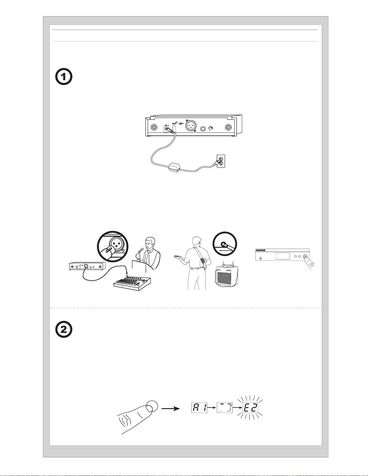
Connect receiver to power source.
Collegate il ricevitore alla presa di alimentazione.
Brancher le récepteur à une source d'alimentation.
Подключите приемник к источнику питания.
Den Empfänger an die Stromversorgung
Sluit ontvanger aan op voedingsbron.
a)
anschließen.
Conecte el receptor a la fuente de alimentación.
① ②
ANTENNA B
POWER
MIC OUT INSTRUMENT OUT VOLUME ANTENNA A
Connect receiver to mixer or amplifier. Press
Conecte el receptor a la mezcladora o amplificador. Oprima el botón
the power button to turn on the receiver.
de alimentación para encender el receptor.
Brancher le récepteur à un mélangeur ou un am-
Collegate il ricevitore al mixer o all'amplificatore. Premete il
plificateur. Appuyer sur le bouton d'alimentation
b)
pulsante power per accendere il ricevitore.
pour allumer le récepteur.
Подключите приемник к микшеру или усилителю. Чтобы
Den Empfänger an das Mischpult oder den
включить приемник, нажмите кнопку Power.
Verstärker anschließen. Die Taste power drücken,
um den Empfänger einzuschalten.
Sluit ontvanger aan op mengpaneel of versterker. Druk op
de aan/uit-knop om de ontvanger in te schakelen.
BLX4R
group channel
(A-Y) (0-9)
① ②
BLX4R
group channel
(A-Y) (0-9)
ANTENNA B
POWER
MIC OUT INSTRUMENT OUT VOLUME ANTENNA A
Press group button on receiver to perform
Premete il pulsante group sul ricevitore per es-
a group scan.
eguire una ricerca del gruppo.
Appuyer sur le bouton group du récepteur pour ef-
Чтобы выполнить сканирование групп,
fectuer un balayage des groupes.
нажмите на приемнике кнопку Group.
Am Empfänger die group-Taste drücken, um
einen Gruppensuchlauf durchzuführen.
Druk op de knop 'group' op de ontvanger om een
groepsscan uit te voeren.
Oprima el botón de grupo en el receptor para
realizar un escaneo de grupo.
group
(A-Y)
5
Install batteries and turn on transmitter.
Installate le pile ed accendete il trasmettitore.
a)
Installer les piles et allumer l’émetteur.
Вставьте батарейки и включите передатчик.
Die Batterien/Akkus einlegen und den
Sender einschalten.
Plaats de batterijen en schakel de zender in.
Instale las baterías y encienda el transmisor.
group
(A-Y)
channel
(0-9)
On the transmitter, set the group and channel to
Sul trasmettitore impostate il gruppo ed il canale corrispon-
b)
match the receiver. The RF bars and battery LED
denti a quelli del ricevitore. Le barre RF ed il LED della pila
on the receiver should illuminate.
situati sul ricevitore devono illuminarsi.
Sur l'émetteur, régler le groupe et le canal afin qu'ils corre-
Установите на передатчике группу и канал
spondent à ceux du récepteur. Les barres RF et la LED des
для согласования с настройкой приемника.
piles du récepteur doivent s'allumer.
На приемнике должны загореться индикаторы
интенсивности РЧ сигнала и светодиод батарейки.
Am Sender Gruppe und Kanal entsprechend
der Empfängereinstellung einstellen. Auf dem
Stel de groep en het kanaal op de zender in zodat
Empfänger sollten die HF-Balken und Akku-LEDs
deze overeenkomen met de ontvanger. De RF-balkjes
aufleuchten.
en batterij-LED op de ontvanger lichten op.
En el transmisor, seleccione el grupo y canal para
que coincidan con el receptor. Se deben iluminar las
barras de RF y el LED de batería en el receptor.
group channel
group
channel
group
channel
channel
group
group
6
group
group
-10 dB
channel
5 s
-10 dB
channel
group
(A-Y)
channel
(0-9)
If setting up additional systems, leave the first transmitter and receiver on. For each additional receiver, manually set the group to match the
first receiver. Note: The receiver will automatically perform a channel scan to find an available frequency after the group has been selected. Set
the transmitter frequency to match the receiver.
Si l'on configure d'autres systèmes, laisser les premiers émetteur et récepteur allumés. Pour chaque système supplémentaire, régler manuelle-
ment le groupe pour qu'il corresponde à celui du premier récepteur. Remarque : une fois le groupe sélectionné, le récepteur exécutera automa-
tiquement un scan des canaux afin de trouver une fréquence disponible. Régler la fréquence de l'émetteur pour qu'elle corresponde à celle du
récepteur.
Falls weitere Systeme eingerichtet werden, den ersten Sender und Empfänger eingeschaltet lassen. Für jeden weiteren Empfänger die Gruppe
manuell auf den ersten Empfänger einstellen. Hinweis: Der Empfänger führt automatisch einen Kanalscan durch, um nach der Auswahl der
Gruppe eine verfügbare Frequenz zu finden. Die Senderfrequenz entsprechend der des Empfängers einstellen.
Si está configurando sistemas adicionales, deje encendidos el primer transmisor y receptor. Por cada receptor adicional, fije manualmente el
grupo para hacerlo coincidir con el primer receptor. Nota: El receptor automáticamente realizará un escaneo de canales para encontrar una
frecuencia disponible después que se ha seleccionado el grupo. Fije la frecuencia del transmisor para que coincida con el receptor.
Se impostate altri sistemi, lasciate accesi il primo trasmettitore e ricevitore. Per ciascun ricevitore aggiuntivo, impostate manualmente il gruppo
in modo che corrisponda al quello del primo ricevitore. Nota: all'avvenuta selezione del gruppo il ricevitore esegue automaticamente una
scansione del canale per individuare una frequenza disponibile. Impostate la frequenza del trasmettitore in modo che corrisponda a quella del
ricevitore.
Пр настройке дополнительных систем оставьте включенными первый передатчик и приемник. Для каждого дополнительного
приемника вручную установите группу, соответствующую первому приемнику. Примечание. После выбора группы приемник
автоматически выполнит сканирование каналов и найдет свободную частоту. Согласуйте частоты передатчика и приемника.
Bij het instellen van aanvullende systemen laat u de eerste zender en ontvanger AAN staan. Stel handmatig voor elke aanvullende ontvanger
de groep zo in dat deze overeenkomt met de eerste ontvanger. Opmerking: Wanneer de groep is geselecteerd, voert de ontvanger automatisch
een kanaalscan uit om een beschikbare frequentie te zoeken. Stel de zenderfrequentie zo in dat deze overeenkomt met de ontvanger.
If sound is too faint or distorted, adjust the
Se il suono è troppo debole o distorto, regolate il
gain accordingly.
guadagno di conseguenza.
Si le son est trop faible ou distordu, régler le gain en
Если звук слишком слабый или искажен,
conséquence.
подрегулируйте усиление.
Falls der Ton zu schwach oder verzerrt ist, die Verstärkung
Als het geluid te zacht of vervormd is, regel dan
dementsprechend korrigieren.
de versterkingsfactor hierop af.
Si el sonido es demasiado débil o distorsionado,
ajuste la ganancia según sea necesario.
7

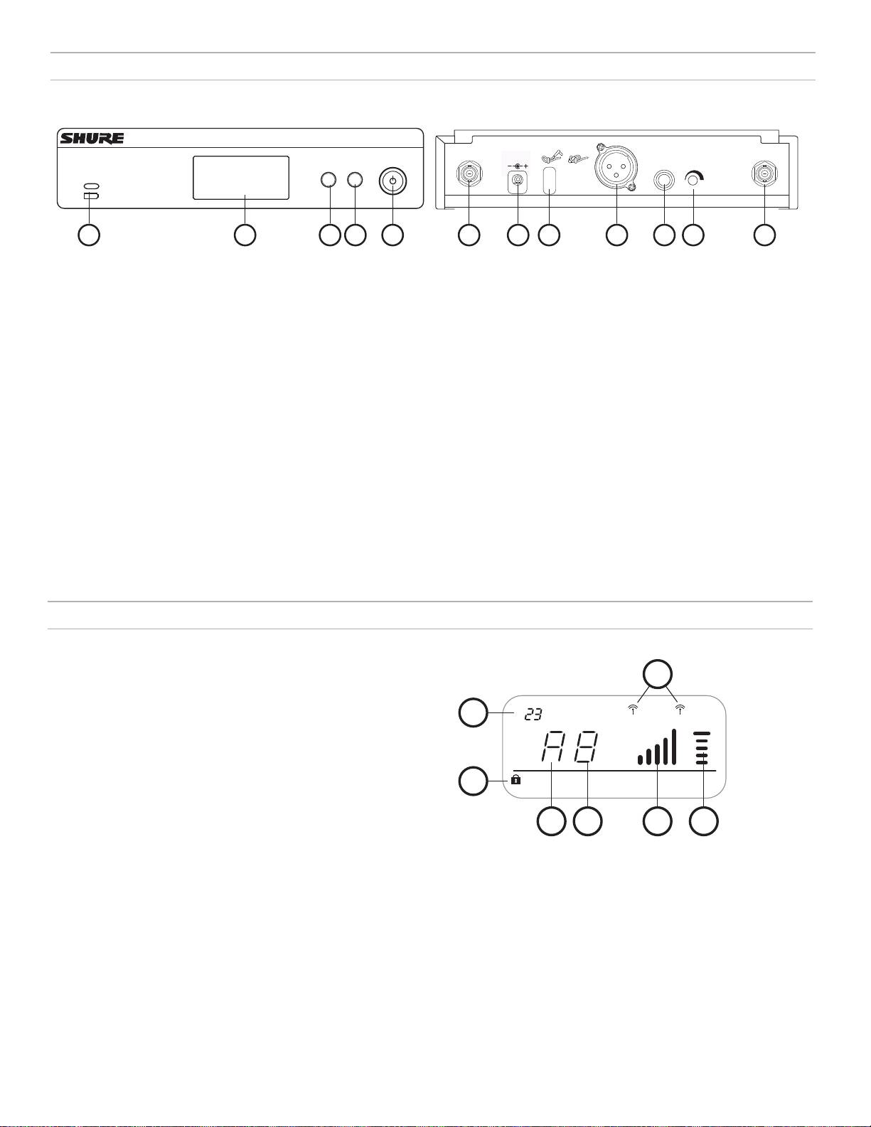
BLX4R Receiver
Front Panel
Rear Panel
BLX4R
group channel
(A-Y ) (0-9)
ANTENNA B
POWER
MIC OUT INSTRUMENT OUT VOLUME ANTENNA A
21
3
4
5 6
7
98
1110
12
① Transmitter Battery LED
④ channel Button
⑧ Strain-relief loop for power cord
• Green = Runtime greater than 1 hour
• Scan: push and release channel button to
Secures power cord to receiver.
• Red = Runtime less than 1 hour
scan for an open channel
⑨ Mic Out XLR audio output jack
• Manual: push and hold channel button to se-
② LCD Display
Supplies microphone-level audio output.
lect a channel.
Displays receiver and transmitter
⑩ INST Out audio output jack
⑤ Power Button
settings.
Supplies instrument-level audio signal.
Powers the receiver on/off.
③ group Button
⑪ Volume Control
⑥ Antenna Jack B
• Scan: push and release group but-
Use a screwdriver to adjust the output
ton to scan for an open group and
BNC connector for antenna B.
level.
channel
⑦ DC Power Jack
• Manual: push and hold group button
⑫ Antenna Jack A
For DC external power supply (12 to 15 V DC).
to select a group.
BNC connector for antenna A.
Receiver LCD Screen
① TV Channel
TV channel for selected frequency.
7
② Receiver Lock
Indicates control and power lock enabled.
1
tv
A
B
③ Group
OL
OL
Displays selected group.
④ Channel
Displays selected channel.
group channel rf
audio
2
⑤ RF Signal Strength
Number of bars corresponds to RF signal strength. OL indicates
signal overload.
3
4
5 6
⑥ Audio Meter
Number of bars indicates audio signal level. OL indicates signal
clipping.
⑦ Active Antenna Indicator
Indicates active antenna for the diversity signal.
8
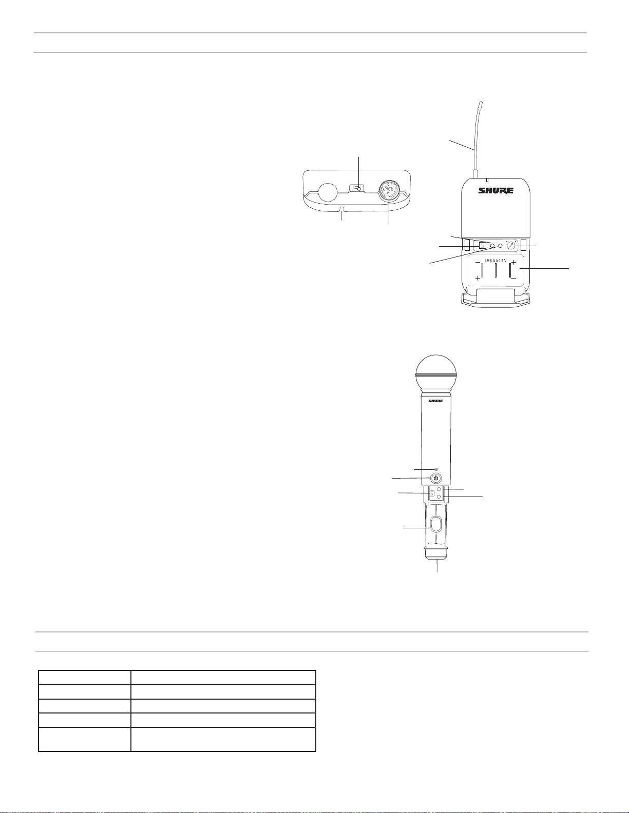
Transmitters
BLX1
① LED Indicator
Displays power and battery status (see table).
BLX1
② power Switch
Toggles power on or off.
④
③ 4-Pin Microphone Input Jack (TA4 connector)
②
④ Antenna
⑤ group Button
Changes group setting.
⑥ LED Display
Displays group and channel setting.
⑦ channel Button
①
③
⑤
group
channel
Changes channel setting.
⑥
(A-Y)
(0-9)
⑨
⑧ Battery Compartment
⑦
⑨ Audio Gain Adjustment
⑧
Rotate to increase or decrease transmitter gain.
BLX2
① LED Indicator
BLX2
Displays power and battery status (see table).
② power Button
Push to turn power on or off.
③ group Button
Changes group setting.
④ channel Button
Changes channel and gain setting.
①
⑤ LED Display
②
Displays group and channel setting.
group
③
⑤
-10 dB
channel
④
⑥ Identification Cap
⑦ Battery Compartment
⑦
⑥
Transmitter LED Indicators
LED Indicator Status
Green Ready
Rapidly Flashing Red Controls locked
Solid Red Battery power low (less than 1 hour remaining*)
Flashing Red and shuts
Batteries dead (change batteries to power on
off
transmitter)
*For alkaline batteries only. For rechargeable batteries, solid red means the batteries are dead.
9
group
(A-Y)
group
channel
group
channel
channel
group
group
Single System Set Up
Before you begin, turn off all transmitters and turn on any equipment (other
microphones or personal monitoring systems) that could cause interference
during the performance.
1. Press and release the group button on the receiver.
The receiver scans for the clearest group and channel.
Note: If you want to stop the scan, push the group button again.
2. Turn on transmitter and change the group and channel to match the re-
ceiver (See Setting Transmitter Group and Channel).
Once the system is set up, perform an audio check and adjust the gain if necessary.
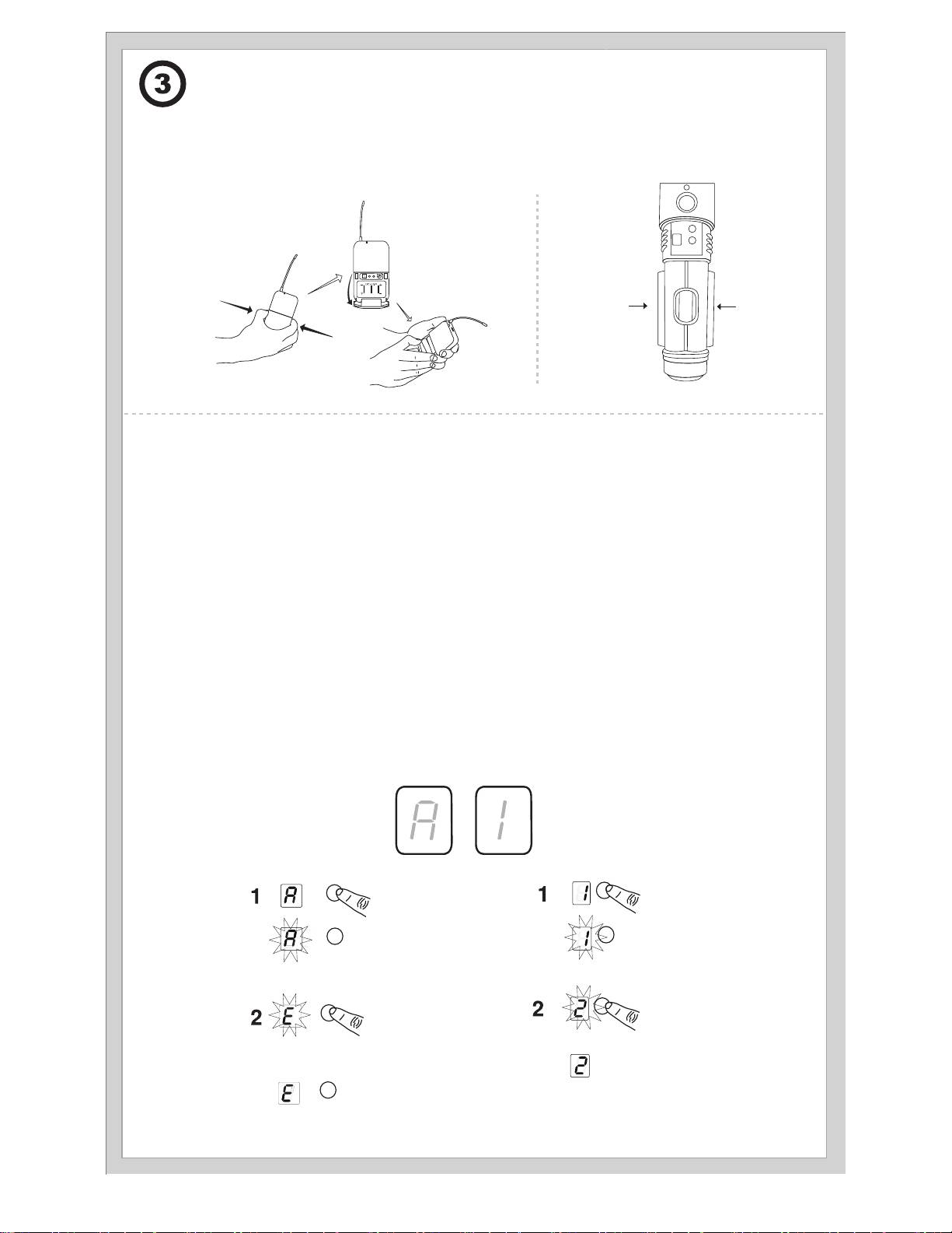
Setting Transmitter Group and Channel
Transmitter group and channel must be manually set to match the receiver.
Group (letter)
Channel (number)
1. Press and release the group button on the transmitter to acti-
If channel needs to be changed, follow the same procedure using the channel
vate the display. Press the group button again and the display
button instead of the group button.
flashes.
Note:
2. While the display is flashing, press the group button again to ad-
vance to the desired group setting.
• When the group and channel correctly match the receiver, the RF bars
and battery LED on the receiver illuminate.
• After manual setup, the transmitter alternately displays the group and
channel setting for about two seconds.
group channel
10

Multiple System Set Up
Up to 12 systems can operate simultaneously (band and RF environment dependent).
Important: Set up each system one-at-a-time. Once a receiver and transmitter are tuned to the same group and channel, leave the transmitter powered
on. Otherwise, scans from the other receivers will not detect that channel as occupied.
Turn on any other equipment that could cause interference during the performance so it will be detected during the group and channel scans in the fol-
lowing steps.
Before you begin system set up, turn all receivers
ON and all transmitters OFF.
For the first receiver:
1. Perform a group scan to find the group with the most clear channels.
2. Turn on the first transmitter and change the group and channel to match the receiver.
3. Leave the transmitter on and continue with the additional systems.
Note: If the selected group does not contain enough open channels, manually select group "d" when setting up larger systems.
For each additional receiver:
1. Manually change the receiver to match the group setting of the first receiver. Recall that each time the group setting is changed, a channel scan is
automatically done.
2. Turn on the transmitter and change the group and channel to match the receiver.
3. Leave the transmitter on and continue to the next system.
4. Once all receivers are set up, perform an audio check on all microphones.
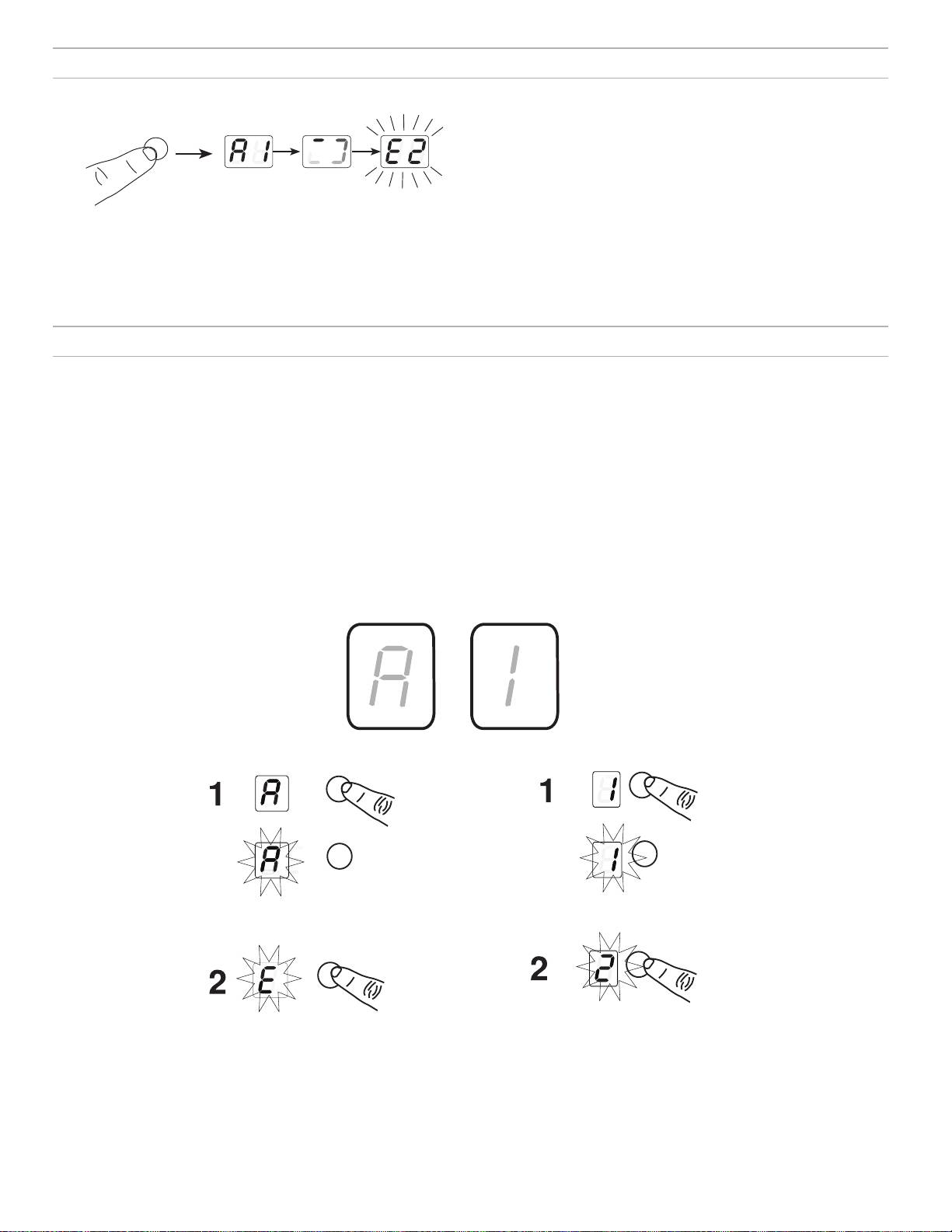
Manually Setting Receiver Group and Channel
The receiver group may need to be changed as part of a multiple system setup.
Group (letter)
1. Hold the group button on the receiver until the display begins to flash.
2. While the display is flashing, press the group button again to advance to the next group.
Note: Only the group setting will be displayed during the manual setup.
3. Once the desired group is reached, release the group button. The receiver automatically performs a channel scan.
Channel (number)
Always use a channel selected by the channel scan. However, if necessary, the channel can be set manually. Follow the same steps above using the
channel button instead of the group button.
11
group
(A-Y)
channel
(0-9)
group
group
-10 dB
channel
-10 dB
channel
5 s
13 mm
(.5 in.)
Tips to Improve Wireless System Performance
If you encounter interference or dropouts, try the following suggestions:
• Choose a different receiver channel
• Remove nearby sources of wireless interference, such as cell phones,
two-way radios, computers, media players, Wi-Fi devices, and digital
• Reposition the receiver so there is nothing obstructing a line of
signal processors
sight to the transmitter (including the audience)
• Charge or replace the transmitter battery
• Avoid placing transmitter and receiver where metal or other
dense materials may be present
• Keep transmitters more than two meters (6 feet) apart
• Move the receiver to the top of the equipment rack
• Keep the transmitter and receiver more than 5 meters (16 feet) apart
• During sound check, mark trouble spots and ask presenters or
performers to avoid those areas
Getting Good Sound
Correct Microphone Placement
• Hold the microphone within 12 inches from the sound source. For a warmer sound with
increased bass presence, move the microphone closer.
• Do not cover grille with hand.
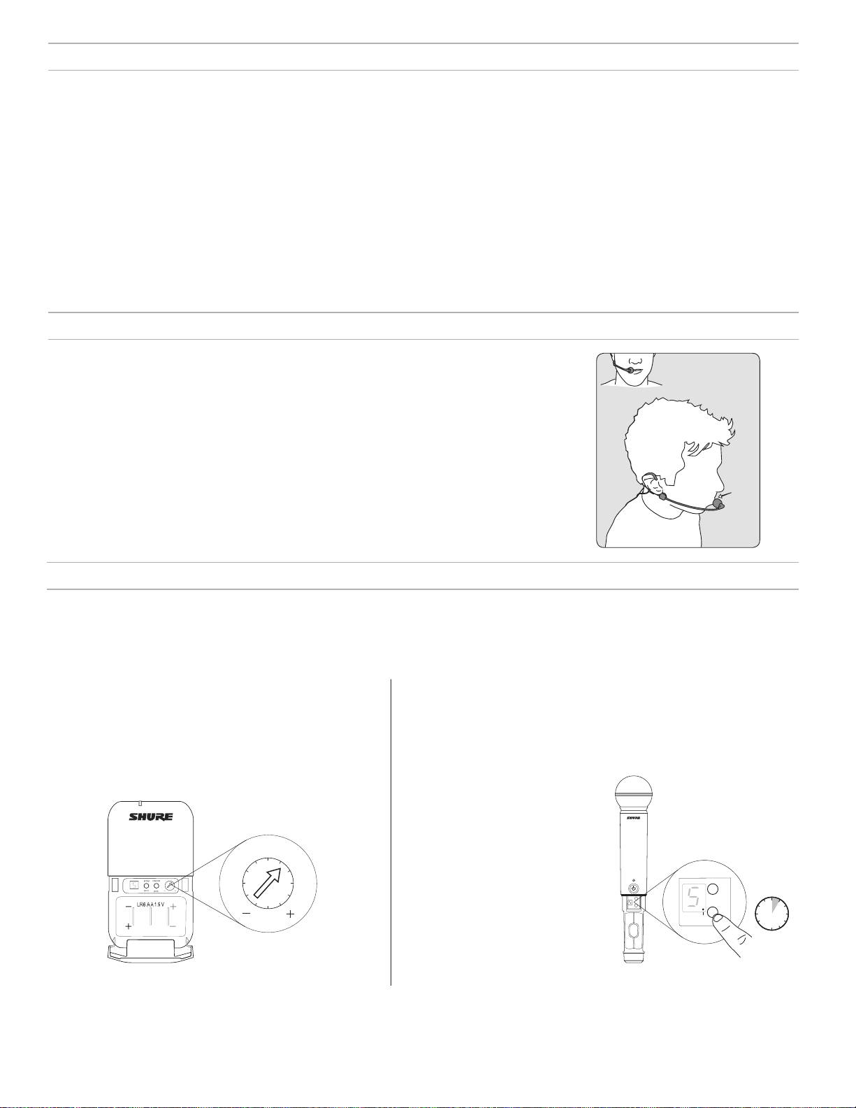
Wearing the Headworn Microphone
• Position the headworn microphone 13 mm (1/2 in.) from the corner of your mouth.
• Position lavalier and headworn microphones so that clothing, jewelry, or other items do not
bump or rub against the microphone.
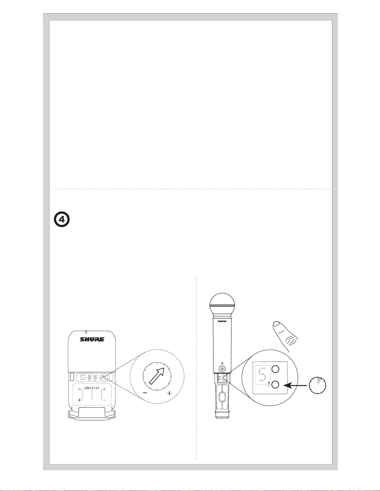
Adjusting Gain
Monitor the audio meter on the receiver display when setting the transmitter gain. The OL indicator should only illuminate infrequently when you speak
loudly or play your instrument loudly.
BLX1
BLX2
Rotate the audio gain adjustment to increase (+) or decrease
(−) the gain until desired level is reached.
The BLX2 features two gain level settings:
For instruments, turn gain to minimum setting. For lavaliers,
•
Default
increase the gain as desired.
• -10 dB
Use the default setting for most
situations. If the receiver audio OL
indicator displays often, set the mi-
crophone to -10 dB.
1. To change the gain to -10 dB,
hold down the channel button
until a small dot appears in the
lower right hand corner of the
transmitter display.
2. To change the gain back to de-
fault, hold the channel button
until the dot disappears.
12
Batteries
Expected life for AA batteries is up to 14 hours (total battery life varies depending upon battery
type and manufacturer).
When the LED indicator turns red, it signifies "low battery" with approximately 60 minutes of re-
maining battery life.
For alkaline batteries only. For rechargeable batteries, solid red means the batteries are dead.
To remove batteries from the handheld transmitter, push them out through the opening in the
microphone battery compartment.
WARNING: Danger of explosion if battery incorrectly
replaced. Operate only with Shure compatible batteries.
WARNING: Battery packs shall not be exposed to ex-
cessive heat such as sunshine, fire, or the like.
Locking and Unlocking Controls
Lock system controls to prevent accidental setting changes or power-off.
Transmitter (lock/unlock)
Receiver (lock/unlock)
Turn the transmitter on. Hold the group button, then press the channel
Turn the receiver on. Simultaneously hold the group and channel but-
button for approximately 2 seconds. The LED indicator rapidly flashes
ton until the flashing lock icon appears in the lower left-hand corner of
red when locked.
the display, indicating the controls are locked. Repeat to unlock the
controls.
Power Off
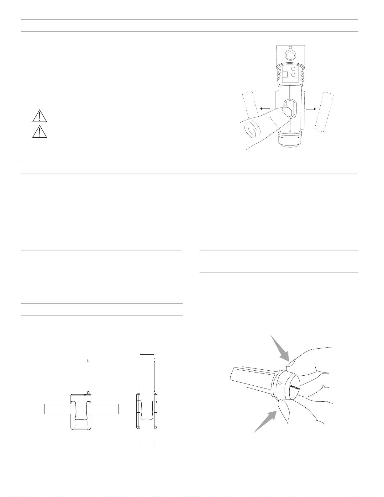
Removing and Installing Identification
Caps
Press and hold the power button to power off the BLX2 or BLX4R. To
power off the BLX1, slide the power switch to OFF.
The BLX2 is equipped with a black identification cap from the factory
(dual vocal systems ship with additional gray cap).
To remove: Remove battery cover. Squeeze sides and pull off cap.
To install: Align the cap and click into place. Replace battery cover.
Wearing the Bodypack Transmitter
An Identification Cap Kit containing assorted colored caps is available
Clip the transmitter to a belt or slide a guitar strap through the transmitter
as an optional accessory.
clip as shown.
For best results, the belt should be pressed against the base of the clip.
13
SHURE INCORPORATED
NILES, IL 60714
ANTENNA B
POWER
MIC OUT LINE OUT ANTENNA A
BXL4R
group channel
(A-Y) (0-9)
SHURE INCORPORATED
NILES, IL 60714
ANTENNA B
POWER
MIC OUT LINE OUT ANTENNA A
BXL4R
group channel
(A-Y) (0-9)
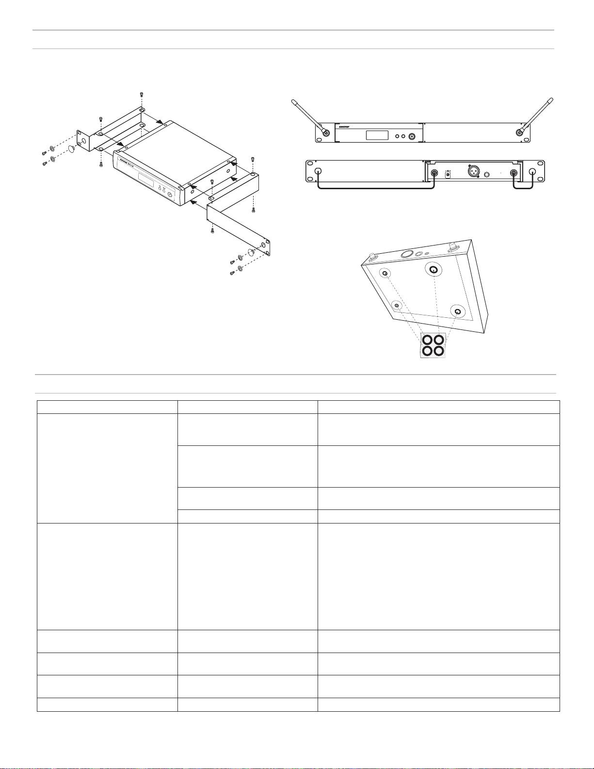
Rack-Mounting a Receiver
Use the supplied mounting hardware to install the receiver in a standard 19" audio equipment rack.
Antenna Connection
Diagram
Troubleshooting
Issue Indicator Status Solution
No sound or faint sound Receiver RF bars and battery LED
• Verify all sound system connections or adjust gain as needed (see
illuminated
Adjusting Gain)
• Verify that the receiver is connected to mixer/amplifier
Receiver RF bars and battery LED off • Turn on transmitter
• Make sure the batteries are installed correctly
• Perform transmitter setup (see Single System Setup)
• Insert fresh batteries
Receiver screen off • Make sure AC adapter is securely plugged into electrical outlet.
• Make sure receiver is powered on.
Transmitter indicator LED flashing red Replace transmitter batteries (see Changing Batteries).
Audio artifacts or dropouts Receiver RF bars and battery LED
• Change receiver and transmitter to a different group and/or
flickering
channel.
• Identify nearby sources of RF interference, and shutdown or re-
move source.
• Replace transmitter batteries.
• Ensure that receiver and transmitter are positioned within system
parameters
• System must be set up within recommended range and receiver
kept away from metallic surfaces.
• Transmitter must be used in line of sight from receiver for optimal
sound
Distortion Audio meter on receiver indicates
Reduce transmitter gain (see Adjusting Gain).
overload (OL)
Sound level variations when switching
N/A Adjust transmitter gain as necessary (see Adjusting Gain).
to different sources
Receiver/transmitter won't turn off LED indicator flashing rapidly, lock
See Locking and Unlocking Controls.
icon shown on receiver display
Transmitter beyond receiver range Receiver display dimmed to 50% Move transmitter closer to receiver
14
Specifications
System
BLX2
Working Range
Audio Input Level
91 m (300 ft) Line of Sight
gain position 0dB -20 dBV maximum
Note: Actual range depends on RF signal absorption, reflection and interference.
-10dB -10 dBV maximum
Audio Frequency Response
50 to 15,000 Hz
Gain Adjustment Range
Note: Dependent on microphone type
10 dB
Total Harmonic Distortion
Ref. ±33 kHz deviation with 1 kHz tone
RF Transmitter Output
0.5%, typical
10 mW, typical
varies by region
Dynamic Range
Dimensions
100 dB, A-weighted, typical
224 mm X 53 mm L x Dia.
Operating Temperature
Weight
-18°C (0°F) to 57°C (135°F)
Note: Battery characteristics may limit this range.
218 g (7.7 oz.) (without batteries)
Polarity
Housing
Positive pressure on microphone diaphragm (or positive voltage ap-
Molded ABS
plied to tip of WA302 phone plug) produces positive voltage on pin 2
Power Requirements
(with respect to pin 3 of low-impedance output) and the tip of the high
2 LR6 AA batteries, 1.5 V, alkaline
impedance 1/4-inch output.
Battery Life
up to 14 hours (alkaline)
BLX1
BLX4R
Audio Input Level
Output Impedance
gain position max -16 dBV maximum
XLR connector 200 Ω
min (0 dB) +10 dBV maximum
6.35 mm (1/4") connec-
50 Ω
tor
Gain Adjustment Range
26 dB
Audio Output Level
Ref. ±33 kHz deviation with 1 kHz tone
Input Impedance
1 MΩ
XLR connector –20.5 dBV (into 100 kΩ load)
RF Transmitter Output
6.35 mm (1/4") connec-
–13 dBV (into 100 kΩ load)
10 mW, typical
tor
varies by region
RF Sensitivity
Dimensions
-105 dBm for 12 dB SINAD, typical
110 mm X 64 mm X 21 mm H x W x D
Image Rejection
Weight
>50 dB, typical
75 g (2.6 oz.), without batteries
Dimensions
Housing
50 mm X 198 mm X 163 mm H x W x D
Molded ABS
Weight
Power Requirements
without antennas
2 LR6 AA batteries, 1.5 V, alkaline
998 g (2.2 lb.)
Battery Life
Housing
up to 14 hours (alkaline)
Molded ABS, steel
Power Requirements
12–15 V DC @ 260 mA, supplied by external power supply (tip positive)
15

Certifications
This Class B digital apparatus complies with Canadian ICES-003. Cet appareil numérique de la classe B est conforme à la norme NMB-003 du Canada.
Meets requirements of the following standards: EN 300 422 Parts 1 and 2, EN 301 489 Parts 1 and 9, EN60065.
Meets essential requirements of the following European Directives:
• R&TTE Directive 99/5/EC
• WEEE Directive 2002/96/EC, as amended by 2008/34/EC
• RoHS Directive 2002/95/EC, as amended by 2008/35/EC
Note: Please follow your regional recycling scheme for batteries and electronic waste
Approved under the Declaration of Conformity (DoC) provision of FCC Part 15.
Certified by IC in Canada under RSS-123 and RSS-102.
Certified under FCC Part 74.
Certified by IC in Canada under RSS-123 and RSS-102.
FCC ID: DD4BLX1A, DD4BLX1B, DD4BLX1C, DD4BLX1D; DD4BLX2A, DD4BLX2B, DD4BLX2C, DD4BLX2D. IC: 616A-BLX1A, 616A-BLX1B,
616A-BLX1C, 616A-BLX1D; 616A-BLX2A, 616A-BLX2B, 616A-BLX2C, 616A-BLX2D
This device complies with Industry Canada licence-exempt RSS standard(s). Operation of this device is subject to the following two conditions: (1) this
device may not cause interference, and (2) this device must accept any interference, including interference that may cause undesired operation of the
device.
Le présent appareil est conforme aux CNR d'Industrie Canada applicables aux appareils radio exempts de licence. L'exploitation est autorisée aux deux
conditions suivantes : (1) l'appareil ne doit pas produire de brouillage, et (2) l'utilisateur de l'appareil doit accepter tout brouillage radioélectrique subi,
même si le brouillage est susceptible d'en compromettre le fonctionnement.
The CE Declaration of Conformity can be obtained from Shure Incorporated or any of its European representatives. For contact information please visit
www.shure.com
The CE Declaration of Conformity can be obtained from: www.shure.com/europe/compliance
Authorized European representative:
Shure Europe GmbH
Headquarters Europe, Middle East & Africa
Department: EMEA Approval
Jakob-Dieffenbacher-Str. 12
75031 Eppingen, Germany
Phone: 49-7262-92 49 0
Fax: 49-7262-92 49 11 4
Email: EMEAsupport@shure.de
LICENSING INFORMATION
Licensing: A ministerial license to operate this equipment may be required in certain areas. Consult your national authority for possible requirements.
Changes or modifications not expressly approved by Shure Incorporated could void your authority to operate the equipment. Licensing of Shure wireless
microphone equipment is the user’s responsibility, and licensability depends on the user’s classification and application, and on the selected frequency.
Shure strongly urges the user to contact the appropriate telecommunications authority concerning proper licensing, and before choosing and ordering
frequencies.
Information to the user
This equipment has been tested and found to comply with the limits for a Class B digital device, pursuant to Part 15 of the FCC Rules. These limits are
designed to provide reasonable protection against harmful interference in a residential installation. This equipment generates uses and can radiate radio
frequency energy and, if not installed and used in accordance with the instructions, may cause harmful interference to radio communications. However,
there is no guarantee that interference will not occur in a particular installation. If this equipment does cause harmful interference to radio or television
reception, which can be determined by turning the equipment off and on, the user is encouraged to try to correct the interference by one or more of the
following measures:
• Reorient or relocate the receiving antenna.
• Increase the separation between the equipment and the receiver.
• Connect the equipment to an outlet on a circuit different from that to which the receiver is connected.
• Consult the dealer or an experienced radio/TV technician for help.
Note: EMC conformance testing is based on the use of supplied and recommended cable types. The use of other cable types may degrade EMC
performance.
Changes or modifications not expressly approved by the manufacturer could void the user’s authority to operate the equipment.
16
Récepteur BLX4R
Panneau avant Panneau arrière
BLX4R
group channel
(A-Y ) (0-9)
ANTENNA B
POWER
MIC OUT INSTRUMENT OUT VOLUME ANTENNA A
21
3
4
5 6
7
98
1110
12
① LED des piles de l'émetteur
④ Bouton channel
⑨ Prise de sortie audio XLR pour sortie
• Vert = durée de fonctionnement supéri-
• Balayage : appuyer sur le bouton channel et
micro
eure à une heure
le relâcher pour rechercher un canal ouvert
Fournit une sortie audio niveau
• Rouge = durée de fonctionnement inféri-
• Manuel : appuyer sur le bouton channel sans
microphone.
eure à une heure
le relâcher pour sélectionner un canal.
⑨ Prise de sortie audio pour sortie
② Écran LCD
⑤ Bouton d'alimentation
instrument
Affiche les paramètres du récepteur et de
Met le récepteur sous tension et hors tension.
Fournit un signal audio niveau instrument.
l'émetteur.
⑥ Jack d’antenne B
⑪ Commande de volume
③ Bouton group
Connecteur BNC destiné à l'antenne B.
Régler le niveau de sortie à l'aide d'un
• Balayage : appuyer sur le bouton group
tournevis.
⑦ Prise d'alimentation c.c.
et le relâcher pour rechercher un groupe
⑫ Jack d’antenne A
et un canal ouverts
Destiné à une alimentation externe c.c. (12 à
• Manuel : appuyer sur le bouton group
15 V c.c.).
Connecteur BNC destiné à l'antenne A.
sans le relâcher pour sélectionner un
⑧ Serre-câble pour le cordon d'alimentation
groupe.
Fixe le cordon d'alimentation au récepteur.
Écran LCD du récepteur
① Canal de télévision
Canal de télévision pour la fréquence sélectionnée.
7
② Verrouillage du récepteur
Indique que les commandes et l'alimentation sont verrouillées.
A
B
1
tv
③ Groupe
OL
OL
Affiche le groupe sélectionné.
④ Canal
Affiche le canal sélectionné.
group channel rf
audio
2
⑤ Intensité du signal RF
Le nombre de barres correspond à l'intensité du signal RF. OL
indique une surcharge de signal.
3
4
5 6
⑥ Vumètre audio
Le nombre de barres indique le niveau du signal audio. OL indique
l'écrêtage du signal.
⑦ Témoin d'antenne active
Indique l'antenne active pour le signal Diversity.
17

Émetteurs
BLX1
① Témoin LED
Affiche l'état de l'alimentation et des piles (voir tableau).
BLX1
② Interrupteur power
Met l'appareil sous tension ou hors tension.
④
③ Connecteur d’entrée à 4 broches du microphone (connecteur TA4)
②
④ Antenne
⑤ Bouton group
Modifie le réglage du groupe.
⑥ Affichage LED
Affiche le réglage du groupe et du canal.
⑦ Bouton channel
①
③
⑤
group
channel
Modifie le réglage du canal.
⑥
(A-Y)
(0-9)
⑨
⑧ Compartiment pile
⑦
⑨ Réglage du gain audio
⑧
Tourner pour augmenter ou réduire le gain de l'émetteur.
BLX2
① Témoin LED
BLX2
Affiche l'état de l'alimentation et des piles (voir tableau).
② Bouton power
Appuyer dessus pour mettre l'appareil sous tension ou hors
tension.
③ Bouton group
Modifie le réglage du groupe.
④ Bouton channel
①
Modifie le réglage du canal et du gain.
②
⑤ Affichage LED
group
③
⑤
-10 dB
channel
Affiche le réglage du groupe et du canal.
④
⑥ Capuchon d'identification
⑦ Compartiment pile
⑦
⑥
Témoins LED d'émetteur
Témoin LED État
Vert Prêt
Clignote rapidement en
Commandes verrouillées
rouge
Rouge continu Piles presque déchargées (autonomie inférieure
à une heure*)
Clignote en rouge et
Énergie des piles épuisée (changer les piles
s'éteint
pour pouvoir allumer l’émetteur)
*Pour les piles alcalines seulement. Pour les piles rechargeables, le témoin rouge allumé en continu signifie que les piles sont déchargées.
18

group
(A-Y)
group
channel
group
channel
channel
group
group
Configuration d'un seul système
Avant de commencer, éteindre tous les émetteurs et allumer tout appareil
(autres microphones ou systèmes de retour personnel) susceptible de
causer des parasites pendant le spectacle.
1. Appuyer sur le bouton group du récepteur et le relâcher.
Le récepteur recherche le groupe et le canal les plus libres.
Remarque : Pour arrêter le balayage, appuyer à nouveau sur le bouton group.
2. Allumer l'émetteur et modifier le groupe et le canal afin qu'ils correspon-
dent à ceux du récepteur (voir la section Réglage du groupe et du canal
de l'émetteur).
Une fois le système configuré, effectuer un test audio et régler le gain si nécessaire.
Réglage du groupe et du canal de l'émetteur
Le groupe et le canal de l'émetteur doivent être réglés manuellement afin de correspondre à ceux du récepteur.
Groupe (lettre)
Canal (chiffre)
1. Appuyer sur le bouton group de l'émetteur et le relâcher pour
Si le canal doit être modifié, suivre la même procédure en utilisant le bouton
activer l'affichage. Appuyer de nouveau sur le bouton group et
channel au lieu du bouton group.
l'affichage clignote.
Remarque :
2. Quand l'affichage clignote, appuyer de nouveau sur le bouton
group pour passer au réglage de groupe désiré.
• Lorsque le groupe et le canal correspondent bien à ceux du récepteur,
les barres RF et la LED des piles du récepteur s'allument.
• Après la configuration manuelle, l'émetteur affiche en alternance le
réglage de groupe et de canal pendant environ deux secondes.
group channel
19

Configuration de plusieurs systèmes
Il est possible d'utiliser jusqu'à 12 systèmes simultanément (selon la disponibilité des bandes et des plages HF).
Important : Configurer chaque système un par un. Une fois qu'un récepteur et un émetteur sont réglés sur le même groupe et le même canal, laisser l'émetteur sous tension. Autrement, les balayages
effectués par les autres récepteurs ne permettront pas de détecter que ce canal est occupé.
Allumer tout autre appareil susceptible de causer des parasites pendant le spectacle de façon à ce qu'il soit détecté pendant les balayages de groupes et de canaux effectués lors des étapes suivantes.
Avant de commencer la configuration des systèmes, ALLUMER tous les récepteurs et ÉTEINDRE tous les émetteurs.
Pour le premier récepteur :
1. Effectuer un balayage de groupes pour trouver le groupe présentant le plus grand nombre de canaux libres.
2. Allumer le premier émetteur et modifier le groupe et le canal afin qu'ils correspondent à ceux du récepteur.
3. Laisser l'émetteur allumé et poursuivre en passant aux autres systèmes.
Remarque : Si le groupe sélectionné ne contient pas assez de canaux ouverts, sélectionner manuellement le groupe « d » lors de configuration de grands systèmes.
Pour chaque récepteur supplémentaire :
1. Modifier manuellement le récepteur afin que son réglage de groupe corresponde à celui du premier récepteur. Il ne faut pas oublier que, chaque fois
que le réglage de groupe est modifié, un balayage des canaux s'effectue automatiquement.
2. Allumer l'émetteur et modifier le groupe et le canal afin qu'ils correspondent à ceux du récepteur.
3. Laisser l'émetteur allumé et poursuivre en passant au système suivant.
4. Une fois tous les récepteurs configurés, effectuer un test audio de tous les microphones.
Réglage manuel du groupe et du canal du récepteur
Dans une configuration à plusieurs systèmes, il peut falloir changer le groupe du récepteur.
Groupe (lettre)
1. Maintenir enfoncé le bouton group du récepteur jusqu'à ce que l'affichage se mette à clignoter.
2. Quand l'affichage clignote, appuyer de nouveau sur le bouton group pour passer au groupe suivant.
Remarque : Seul le réglage du groupe s'affiche pendant l'opération de configuration manuelle.
3. Une fois le groupe désiré atteint, relâcher le bouton group. Le récepteur effectue automatiquement un balayage des canaux.
Canal (chiffre)
Toujours utiliser un canal sélectionné par le balayage des canaux. Toutefois, si nécessaire, il est possible de régler le canal manuellement. Suivre la
procédure ci-dessus en utilisant le bouton channel au lieu du bouton group.
20
