Enermax Revolution87+: instruction
Class: Computer Accessories
Type:
Manual for Enermax Revolution87+

INDEX
Precaution Notice............................................................................................................ 1 ENERMAX REVOLUTION87+ Series Power Supply Specification .............................. 2 ENGLISH ....................................................................................................................... 3 DEUTSCH...................................................................................................................... 8 ESPAÑOL .................................................................................................................... 14 FRANCAIS .................................................................................................................. 19 ITALIANO ................................................................................................................... 24 РУССКИЙ ................................................................................................................... 29 POLSKI ........................................................................................................................ 34

1
Precaution Notice
Only a technician, authorized by ENERMAX, is allowed to perform maintenance service! Warranty is subject to void under unauthorized attempt to open the power case or modification of any kinds, even attempted only, of the power supply or its components! ENERMAX will not be responsible for damages caused by following situations: Opening of the PSU case and/or modification of any component or cable without ENERMAX’s written authorization. Ignoring connector’s wrong insertion prevention design by attaching a connector to a device in wrong orientation. Connecting too many devices to one cable unit by using additional adaptor (Y cables). Usage of non-genuine ENERMAX modular cables. The serial number label or warranty seal is defaced, modified, or removed. Damage caused by natural phenomena or uncontrollable forces, such as lightning, flooding, fire, earthquake, etc. This ENERMAX Technology Corporation product is warranted to be free from defects in material and workmanship for a period of five (5) years from the date of purchase. ENERMAX Technology Corporation agrees to repair or replace the product, at its own option and at no charge, if, during the warranty period, it is returned to nearest ENERMAX Technology Corporation subsidiary/agent with all shipping charges prepaid and bearing a return merchandize authorization (RMA) number, and if inspection reveals that the product is defective. Charges for removing or installing the product are excluded under the terms of this warranty agreement. This warranty shall not apply to any product, which has been subject to connection to a faulty power source, alteration, negligence, or accident, or to any product, which has been installed other than in accordance with these instructions. In no event shall ENERMAX Technology Corporation, or its subsidiaries, or agents be liable for damages for a breach of warranty in an amount exceeding the purchase price of this product! If you are uncertain whether or not your ENERMAX PSU is defective, please contact your dealer/reseller for support!
Web Site: http://www.enermax.com
E-mail: enermax@enermax.com.tw
Forum: forum.enermax.com
ENERMAX Technology Corporation, 15F-2, No. 888, Jing-Guo Road, Taoyuan City (330), Taiwan (R.O.C.), Tel.
+886-3-316-1675, Fax. +886-3-346-6640
©2011 ENERMAX Technology Corporation. All rights reserved. Specifications are subject to change without prior notice. Actual
product and accessories may differ from illustrations. Omissions and printing errors excepted. Content of delivery might differ in
different countries or areas. Some trademarks may be claimed as the property of others. Reproduction in any manner without the
written permission of ENERMAX is strictly forbidden.
2
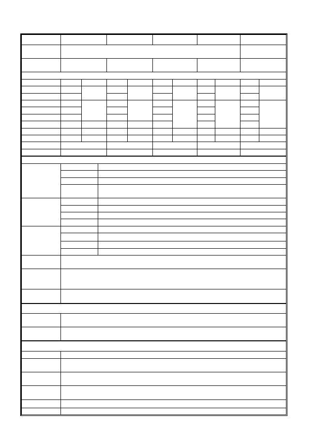
ENERMAX REVOLUTION87+ Series Power Supply Specification
ERV550AWT-G ERV650AWT-G ERV750AWT-G ERV850EWT-G ERV1000EWT-G
AC Input
Voltage
100-240VAC, 50-60Hz
115-240VAC,
50-60Hz
AC Input
Current
7.5 – 3A
8.5 – 3.5A
9 – 4.5A
11 – 5A
11 – 5A
DC OUTPUT
Rated Combined Rated Combined Rated Combined Rated Combined Rated Combined
3.3V
0-24A
0-24A
0-24A
0-24A
0-24A
5V
0-24A
120W
0-24A
120W
0-24A
120W
0-24A
120W
0-24A
120W
12V1
0-25A
0-25A
0-25A
0-30A
0-30A
12V2
0-25A
0-25A
0-25A
0-30A
0-30A
12V3
0-25A
540W
(45A)
0-25A
648W
(54A)
0-25A
0-30A
0-30A
12V4
-
-
-
-
0-25A
744W
(62A)
0-30A
840W
(70A)
0-30A
996W
(83A)
-12V
0-0.5A
6W
0-0.5A
6W
0-0.5A
6W
0-0.5A
6W
0-0.5A
6W
5Vsb
0-3A
15W
0-3A
15W
0-3A
15W
0-3A
15W
0-3A
15W
Total Power
550W
650W
750W
850W
1000W
Peak Power*
605W
715W
825W
935W
1100W
PROTECTION CIRCUIT
DC Rail
OCP trigger range
3.3V
30 – 40A
5V
30 – 40A
Over Current
Protection
12V
30 – 40A (ERV550AWT-G / ERV650AWT-G)
35 – 45A (ERV750AWT-G / ERV850EWT-G / ERV1000EWT-G)
DC Rail
OVP trigger range
3.3V
3.7 – 4.1V
5V
5.7 – 6.5V
Over Voltage
Protection
12V
13.1 – 14.5V
DC Rail
UVP trigger range
3.3V
2.0 – 2.4V
5V
3.3 – 3.7V
(DC)Under
Voltage
Protection
12V
8.5 – 9.5V
Over Power
Protection
Activated when output power > 120 ~150% of rated max load.
Over
Temperature
Protection
Activated when PSU heat sink > 90 ~ 120
o
C.
Short Circuit
Protection
Activated when any DC rails short-circuited.
ENVIRONMENT
Temperature
Operation ambient: 0~50
o
C (for full rated output)
Storage ambient: -40~70
o
C
Humidity
Operation: to 85% relative humidity, non-condensing
Storage: to 95% relative humidity, non-condensing
OTHERS
Cooling
One 13.9cm twist bearing fan, speed auto controlled.
MTBF
> 100,000 hours at 70% of full rated load, 230VAC/50Hz, 25
o
C
(MIL-HDBK-217F standard)
Dimension
150(w) x 86(h) x 160(d) mm (ERV550AWT-G / ERV650AWT-G)
150(w) x 86(h) x 175(d) mm (ERV750AWT-G / ERV850EWT-G / ERV1000EWT-G)
Weight
2kg (without modular cables)±50g (ERV550AWT-G / ERV650AWT-G)
2.9kg(without modular cables)±50g (ERV750AWT-G / ERV850EWT-G / ERV1000EWT-G)
Safety
UL/cUL(Level 6), TUV, GOST, CB, BSMI
EMC
CE, FCC, KCC
*
Peak power may last up to 60 seconds
3
User’s Manual
Dear customer,
Thank you for choosing this ENERMAX power supply unit (PSU)! Please read this manual carefully and
follow its instructions before installing the PSU.
We would like to draw your attention that a computer required very specific conditions to work best for
you without failing. To avoid failures and to increase lifetime of the system, we suggest that:
Your system is NOT located near a radiator or any other heat producing device
Your system is NOT located near a magnetic device
Your system is NOT located in a moist and/or dusty and/or vibrating environment
Your system is NOT exposed to direct sunshine
Your system is sufficiently cooled by additional fans
If you use AC extension cables, please make sure it can support all connected appliances’ potential
peak power draw. Or redistribute other high power consumption equipment, such as laser printers or
monitors to other AC wall outlets. Exceeding the extension cable’s loading capacity could trigger its
circuit breaker and cut off the power.
If you want to add the UPS (Uninterruptible Power Supply) for your system, please choose adequate
Watts/VA capacity UPS.
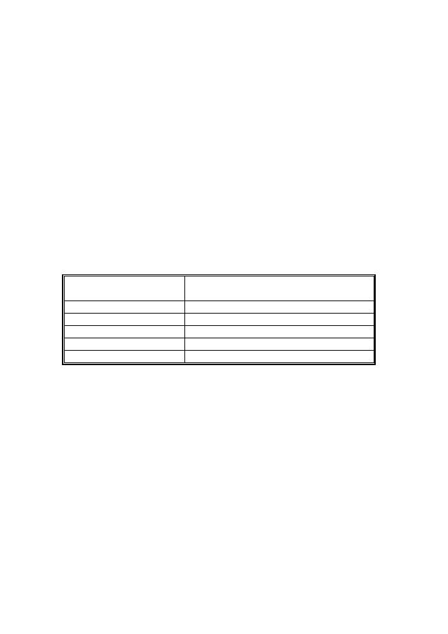
Ex.
PSU Model
Suggested minimum UPS output power capacity
(Based on efficiency & PFC at respective load)
ERV550AWT-G
600W / 1000VA
ERV650AWT-G
700W / 1100VA
ERV750AWT-G
900W / 1400VA
ERV850EWT-G
1000W / 1400VA
ERV1000EWT-G
1100W / 1600VA
*
If you intend to add other appliance powered by the same UPS, such as monitor or printer,
please use higher capacity UPS according to all connected devices’ rated power draw.
*
Please do not mistake VA capacity as Watts, or use insufficient power UPS. This would result
in
less UPS battery runtime or the inability to power the system in battery mode.
4
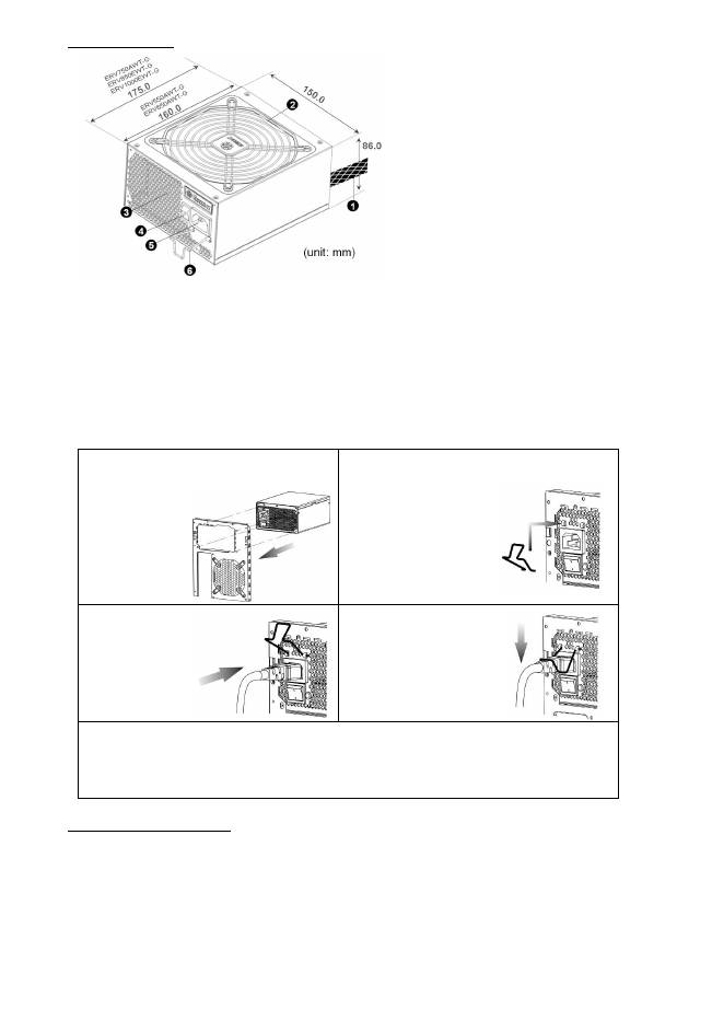
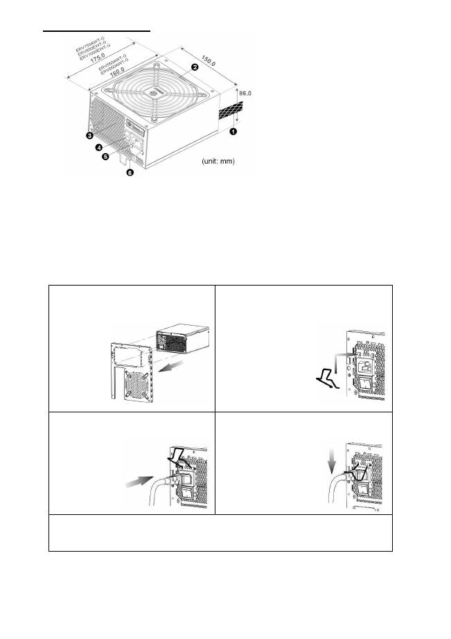
NAME OF PARTS
①
Output cable: Please check “Cables &
Connectors” section.
②
Fan.
# 1
③
Honeycomb air vent.
# 1
④
ON/OFF switch (I=ON, O=OFF).
# 2
⑤
AC Inlet.
# 2
⑥
CordGuard.
#3
#1 To ensure best system cooling, do not block PSU fan’s air in-take and air vent area.
This PSU offers a special HeatGuard function. When the system is turned off, or goes into ACPI
S3/S4 sleep mode, the PSU fan will keep dissipating the remaining heat for 30 ~ 60 seconds and
prolonging system lifetime.
#2 When assembling or maintaining the system, please remove AC cord from AC inlet, or turn
ON/OFF switch into “OFF” position. Then you can safely service the system.
#3 AC cord can get loose in many ways. The ENERMAX CordGuard lock can fix your AC cord tightly
to the PSU, so that it will not be easily detached and avoid shut-downs of your PC. The following
is CordGuard installation:
①
Set your PSU into the chassis, and please
make sure the I/O switch is on “O”
position.
②
Press two sides of the CordGuard lock
together, and set it into
CordGuard holder near
the AC inlet.
③
Plug the AC
cord into your
PSU.
④
Lock CordGuard to
latch onto AC cord.
1.
CordGuard is for AC cords supplied with ENERMAX CordGuard-compatible PSUs. Other AC
cords may be incompatible.
2.
When assembling or maintaining the system, please remove AC cord from AC inlet, or turn I/O
switch into “O” position.
CABLES & CONNECTORS
All connectors are designed to prevent insertion in wrong orientation. If you cannot easily insert a
connector, please check if you are inserting the connector in the right orientation. Do not try by force to
insert it nor modify the connectors. This might damage power supply and system components, and
warranty shall be void.
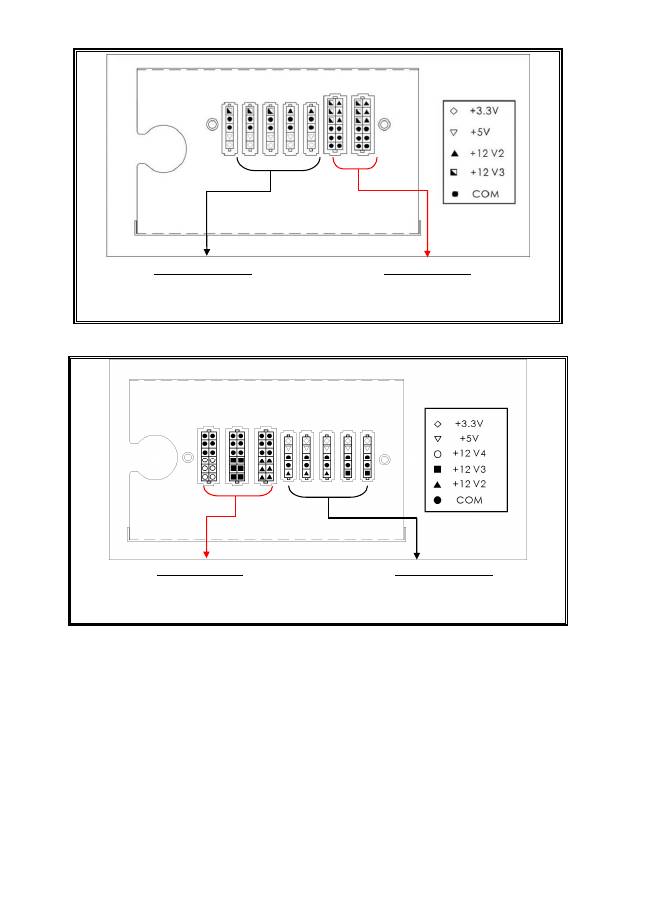
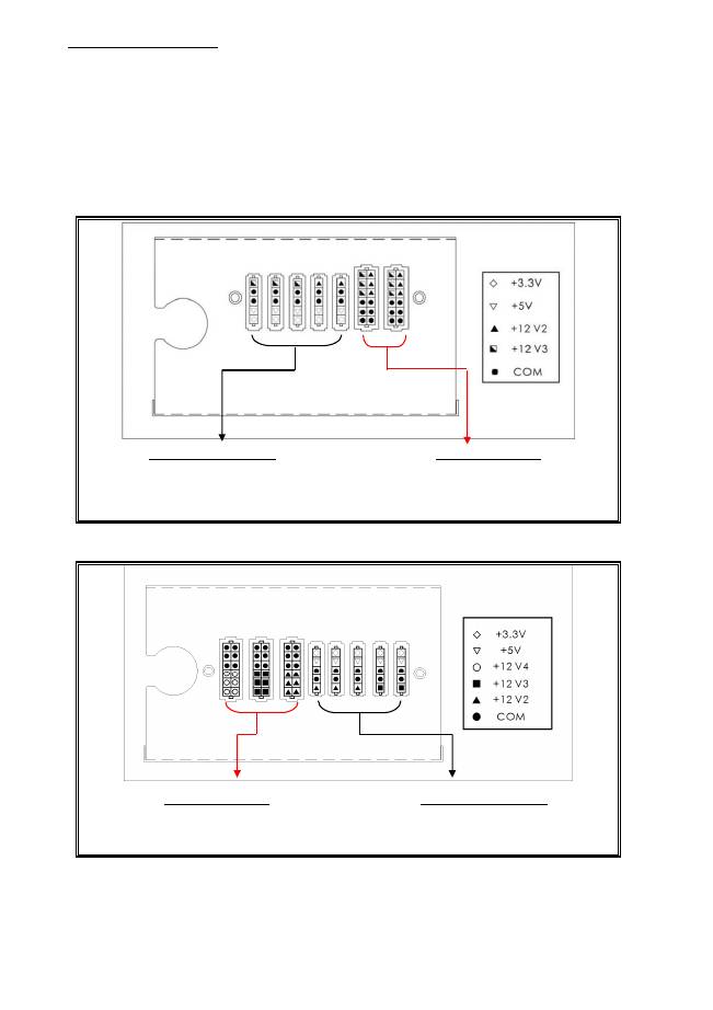
Following graphic illustrates the modular sockets layout and its DC rail distribution.
5
(ERV550AWT-G / ERV650AWT-G)
5P BLACK sockets
The black sockets provide 3.3V/5V/12V for
modular cable to power drives or other
peripheral.
12P RED sockets
The red sockets provide 12V for modular cable
to power graphics card, CPU or RAM.
(ERV750AWT-G / ERV850EWT-G / ERV1000EWT-G)
12P RED sockets
The red sockets provide 12V for modular cable
to power graphics card, CPU or RAM.
5P BLACK sockets
The black sockets provide 3.3V/5V/12V for
modular cable to power drives or other
peripheral.
*
This product incorporates multiple 12V rails over current protection. If you let many peripherals
consume the power on only one 12V rail, it may trigger the over current protection and shut down
the system. Please re-direct certain peripheral power cable to other 12V rail to share the current
loading to ensure highest stability and safety.
6
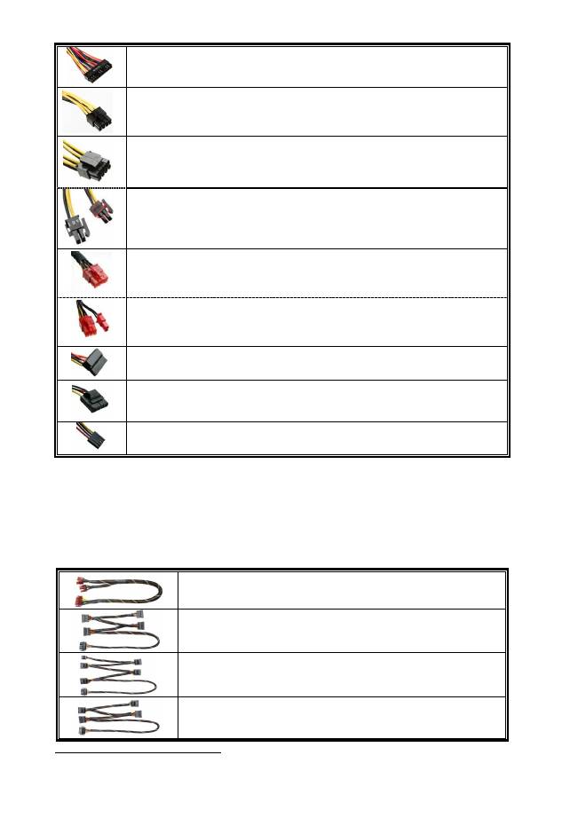
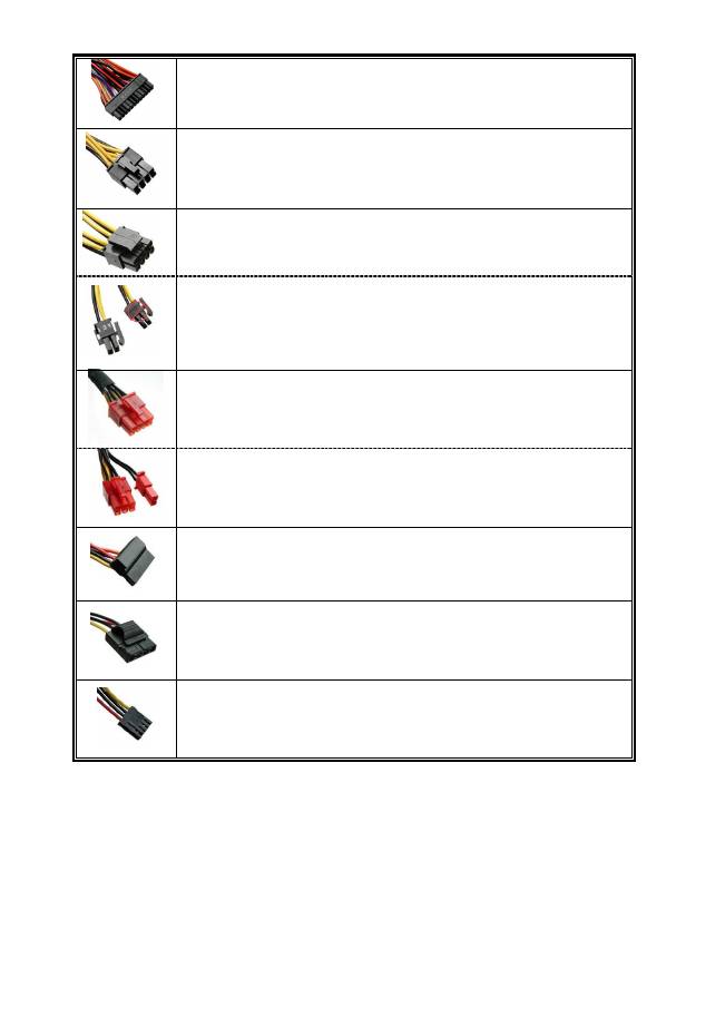
CONNECTOR TYPES
24P Mainboard
For new generations of ATX/EEB/CEB server/workstation MB.
8P CPU +12V
Native cable, 12V rail supplied by 12V1 (750/850/1000W)
8-pin configuration supports multi-CPU server/workstation systems and some single
extreme CPU systems.
4+4P(8P) CPU+12V, in combined mode
Native cable, 12V rail supplied by 12V1
8-pin configuration supports multi-CPU server/workstation systems and some single
extreme CPU systems.
4+4P(8P) CPU+12V, in split mode
Native cable, 12V rail supplied by 12V1
4-pin configuration supports certain single CPU systems. Some multi-CPU
workstation/server system might also need this extra 4-pin 12V connector.
Please use the connector with “12V” marking.
6+2P (8P) PCI Express, in combined mode
12V rail supplied by 12V4 on native cables (850/1000W)
8-pin configuration supports latest extreme graphic cards, which require 8-pin PCI-E
connector.
6+2P (8P) PCI Express, in split mode / 6P PCI Express
12V rail supplied by 12V4 on native cables (850/1000W)
6-pin configuration supports most performance PCI-E graphic cards, which require
6-pin PCI-E connector.
SATA
# 1
For SATA/SAS drives.
4P Molex
# 2
For IDE/SCSI/SAS drives or some AGP graphic card with traditional 4P power in
socket.
FDD
For floppy drive or certain add-on card.
#1
Some SATA drives might accept SATA or 4P Molex power. Normally, use either one of power
connector to power the driver, BUT NOT BOTH! Please check the drive’s manual for details.
#2 Some MB might require this connector to share the +12V current from 24-pin Mainboard connector to
PCI-E slot. If your system has multiple extreme graphic cards, please plug this connector to MB
correspond socket and check the MB’s manual for details.
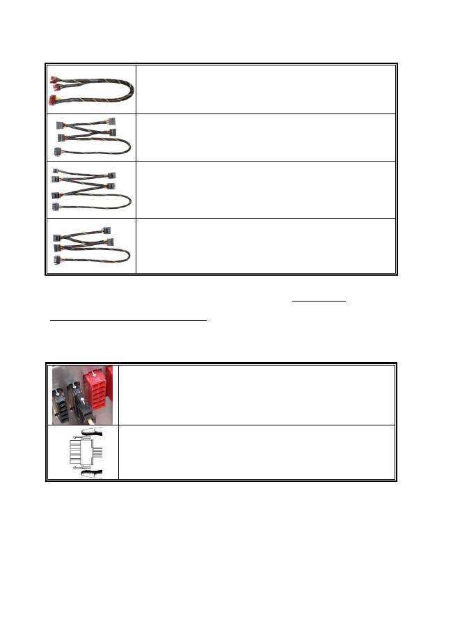
MODULAR CABLES SUPPLIED
Use ONLY genuine ENERMAX modular cables coming with ENERMAX PSU. Third party cables might
not be compatible and might cause damage to your PSU and/or system, and use of third party cable shall
void PSU warranty.
EMC014-G: 2 x 6+2P (8P) PCI-E 2.0
Modular cable for 1 or 2 performance PCI Express graphic cards, which
needs 6P or 8P PCI-E connector.
EMC019-G: 4 x SATA drives
Modular cable for SATA/SAS drives like ODD and HDD.
EMC020-G : 4 x 4P Molex (IDE/SCSI) drives & 1 x FDD connector
Modular cable for IDE/SCSI/SAS drives and peripheral, plus 1 FDD
power connector.
EMC021-G: 2 x SATA & 2 x 4P Molex
Modular cable for SATA/SAS/IDE/SCSI drives and other peripherals.
Special note for System Integrators: If your system requires special modular cable configuration or
design, please contact an ENERMAX sales representative.
7
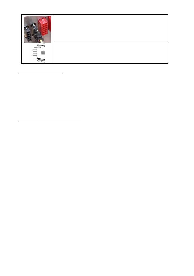
ATTACHING / DETACHING THE MODULAR CABLES
Attaching the modular cable to PSU
5-pin / 12-pin connector on modular cable and PSU’s modular socket has an
arrow mark. To make correct connection is easy:
1.
Black connector to black socket, and red to red.
2.
Arrow mark to arrow mark.
3.
Then you can easily plug in the connector.
Detaching the modular cable from PSU
5-pin / 12-pin connector on modular cable has two hooks to lock with the
PSU’s modular sockets. When unplug the modular cable from PSU, please
press two hooks together and gently pull out the cable.
BOOTING YOUR SYSTEM
Before booting your system, please check that:
1.
Main power connector (24P) is properly connected.
2.
CPU +12V power connector (4 or 8P configuration), and/or a 4P Molex connector (if required by
MB) is properly connected.
3.
All other needed connectors are properly connected.
4.
AC cord is properly connected to wall outlet and PSU AC inlet.
5.
Close your system chassis.
6.
Turn on the PSU by switching the ON/OFF switch to “ON”, and your system is ready.
PROTECTION, SAFETY & SECURITY
This ENERMAX PSU features multiple protections. In case of most abnormal situations, the power
supply will automatically turn off to avoid potential danger to itself and other PC components. It is
usually a malfunction of components or user’s negligence to trigger off a protection event. In such
circumstance, please check your PC devices and working environment for malfunction:
1.
Turn I/O switch of power supply into “O” position, or disconnect AC cord from wall plug and
power supply AC inlet.
2.
Check PSU for temperature by simply touching it. If it is very hot, this can be caused by
malfunction of case fans or the PSU fan itself and/or wrong positioning of your PC.
3.
Wait some minutes until PSU cools off.
4.
Reconnect AC cord to wall plug and power supply AC inlet.
5.
Turn I/O switch of power supply into “I” position, and reboot your system.
6.
Check, if all fans are working.
7.
Contact technical support of the respective manufacturer of the component which you think might
be the cause to the problem. (e.g. MB, GPU or PSU)
If you have any question or need support, please contact your reseller or nearest ENERMAX
subsidiary/agent or ENERMAX headquarter service center.
©2011 ENERMAX Technology Corporation. All rights reserved. Specifications are subject to change without prior notice. Actual
product and accessories may differ from illustrations. Omissions and printing errors excepted. Content of delivery might differ in
different countries or areas. Some trademarks may be claimed as the property of others. Reproduction in any manner without the
written permission of ENERMAX is strictly forbidden.
8
Benutzerhandbuch
Sehr geehrte Kundin, sehr geehrter Kunde,
Vielen Dank, dass Sie sich für dieses ENERMAX-Netzteil (PSU) entschieden haben! Bitte lesen Sie sich
dieses Handbuch sorgfältig durch und folgen Sie bitte seinen Anweisungen bevor Sie das Netzteil
installieren!
Wir möchten Sie darauf hinweisen, dass moderne Systeme sehr empfindlich geworden sind und genau
definierte Bedingungen benötigen, um optimal ohne Ausfälle arbeiten zu können. Um solche Ausfälle zu
vermeiden und die Lebensdauer Ihres Systems zu verlängern, empfehlen wir Ihnen sicherzustellen, dass:
Ihr System nicht neben einer Heizung oder einer anderen Wärmequelle steht.
Ihr System nicht neben einer magnetischen Quelle steht.
Ihr System nicht in einer feuchten und/oder staubigen und/oder vibrierenden Umgebung steht.
Ihr System nicht dem direkten Sonnenlicht ausgesetzt ist.
Ihr System ausreichend durch Lüfter gekühlt wird.
Falls Sie ein Verlängerungskabel verwenden, stellen Sie bitte sicher, dass dieses dazu geeignet ist,
den maximalen Strombedarf sämtlicher angeschlossenen Geräte zu leisten. Andernfalls schließen
Sie bitte weitere viel Strom verbrauchende Geräte (wie Laserdrucker oder Monitor) an eine andere
Steckdose an. Ein Überschreiten der maximalen Durchleitungsfähigkeit des Verlängerungskabels
könnte zu einem Auslösen der Sicherung führen.
Falls Sie eine USV (Unterbrechungsfreie Stromversorgung) verwenden möchten, nutzen Sie bitte
eine mit ausreichender Watt/VA-Kapazität. Z. B.:
PSU Modell
Empfohlene kleinste USV-Kapazität
(gemäß Effizienz & PFC bei entsprechender Last)
ERV550AWT-G
600W / 1000VA
ERV650AWT-G
700W / 1100VA
ERV750AWT-G
900W / 1400VA
ERV850EWT-G
1000W / 1400VA
ERV1000EWT-G
1100W / 1600VA
*
Falls Sie andere Geräte wie Monitor oder Drucker gleichfalls an die selbige USV anschließen
möchten, wählen Sie bitte eine USV mit höherer Kapazität gemäß der Summe der
Leistungsaufnahme aller angeschlossenen Geräte.
*
Bitte verwechseln Sie nicht VA mit Watt und nutzen Sie bitte eine ausreichende USV.
Andernfalls verkürzt sich die Laufzeit der Batterie und gefährdet die Versorgung des Systems
im Batterie-Modus.
9
DETAILBESCHREIBUNG
①
Ausgangskabel: Bitte lesen Sie
den Abschnitt „Kabel &
Anschlüsse“.
②
Lüfter.
# 1
③
Honigwabenluftauslass.
# 1
④
I/O Schalter*: separater
Netzteil An/Aus-Schalter
(I=AN, O=AUS).
# 2
⑤
Stromeingang.
# 2
⑥
CordGuard
# 3
#1 Bitte blockieren Sie nicht die Lufteinlässe/Luftauslässe, um eine bestmögliche Systemkühlung zu gewährleisten.
Dieses PSU verfügt über eine besondere HeatGuard-Funktion: Wenn das System abgeschaltet oder in den ACPI
S3/S4 Schlafmodus gebracht wird, wird der PSU-Lüfter die Restwärme für 30-60 Sek. abführen und so die
Lebensdauer des Systems verlängern.
#2 Entfernen Sie immer das Stromkabel vom Netzteil, schalten Sie den I/O-Schalter auf „O“ und warten Sie, bevor
Sie am System arbeiten.
#3 Der Netzstecker kann sich auf unterschiedliche Weise lösen. Der ENERMAX-CordGuard fixiert den Stecker am
Netzteil. Er verhindert unfreiwillige Systemabstürze durch einen versehentlich gezogenen Netzstecker.
①
Setzen Sie das Netzteil in das Gehäuse
ein. Stellen Sie sicher, dass der
Netzschalter auf “O“ (Aus) steht.
②
Drücken Sie die beiden Seiten des
CordGuard zusammen und befestigen Sie ihn
an der dafür vorgesehenen Stelle.
③
Schließen Sie das Netzkabel am Netzteil
an.
④
Klappen Sie den CordGuard herunter und
sichern Sie auf diese Weise den Netzstecker.
1.
Der CordGuard ist nur f
ü
r Netzkabel geeignet, die mit CordGuard-kompatiblen ENERMAX-Netzteilen
ausgeliefert wurden. Andere Netzkabel sind mit dem ENERMAX-CordGuard ggf. nicht kompatibel.
2.
Beim Zusammenbauen oder bei der Wartung des Systems ziehen Sie bitte immer den Netzstecker oder
stellen Sie den Netzschalter auf “O“(Aus).
10
KABEL & ANSCHLÜSSE
Alle Sockel und Anschlüsse sind so entworfen, dass ein Anschluss in falscher Ausrichtung nahezu
unmöglich ist. Der Anschluss an die kompatiblen Sockel gestaltet sich leichtgängig und ohne größeren
Widerstand. Wenn Sie einen originalen ENERMAX Anschluss nicht auf Anhieb mit einer Komponente
verbinden können, überprüfen Sie bitte, ob Sie die richtige Ausrichtung gewählt haben. Versuchen Sie es
keinesfalls mit Gewalt! Verändern Sie nicht die Anschlüsse! Dies könnte das Netzteil beschädigen und hat
das Erlöschen der Garantie zur Folge!
Folgende Grafik illustriert das Layout der modularen Sockel und deren DC Leitungsverteilung.
(ERV550AWT-G / ERV650AWT-G)
Schwarze 5-Pin Sockel
Schwarze Sockel (3.3V/5V/12V) für modulare
Kabel der Laufwerke (HDD, ODD) oder
Peripheriegeräte.
Rote 12-Pin Sockel
Rote Sockel (12V) für modulare Kabel der
Grafikkarten, CPUs oder RAM.
(ERV750AWT-G / ERV850EWT-G /ERV1000EWT-G)
Rote 12-Pin Sockel
Rote Sockel (12V) für modulare Kabel der
Grafikkarten, CPUs oder RAM.
Schwarze 5-Pin Sockel
Schwarze Sockel (3.3V/5V/12V) für
modulare Kabel der Laufwerke (HDD, ODD)
oder Peripheriegeräte.
* Dieses Netzteil besitzt eine Überstromsicherung (OCP) auf jeder einzelnen 12V-Leitung. Wenn zu viele
Komponenten an einer 12V-Leitung angeschlossen werden, kann es zur Auslösung der Überstromsicherung
kommen. Daher achten Sie bitte auf eine gleichmäßige Verteilung der Komponenten auf die einzelnen
12V-Leitungen, um optimale Stabilität und Sicherheit zu gewährleisten.
11
Anschlusstypen
24P Mainboard
Natives Kabel, 12V Leitung versorgt durch 12V1
Für die neueste Generation von ATX/EEB/CEB Server/Workstation MB’s.
8P CPU +12V
Natives Kabel, 12V Leitung versorgt durch 12V1 (750/850/1000W)
Unterstützt Multi-CPU Server/Workstation-Systeme und einige Ein-Sockel
Systeme.
4+4P (8P) CPU +12V, in “kombiniertem Modus”
Natives Kabel, 12V Leitung versorgt durch 12V1
Unterstützt Multi-CPU Server/Workstation-Systeme und einige
Hochleistungs-Einzel-CPU Systeme.
4+4P (8P) CPU +12V, in “getrenntem Modus”
Natives Kabel, 12V Leitung versorgt durch 12V1
4-Pin Konfiguration unterstützt herkömmliche Einzel-CPU Systeme. Einige
Multi-CPU Systeme benötigen möglicherweise ebenfalls diesen zusätzlich
Stecker.
Bitte verwenden Sie das Modul mit der „+12V” Markierung.
6+2P (8P) PCI Express, in “kombiniertem Modus”
Natives Kabel, 12V Leitung versorgt durch 12V4 (850/1000W)
8-pin Konfiguration unterstützt die neuesten Grafikkarten, welche diesen 8-Pin
PCI-E Stecker benötigen.
6+2P (8P) PCI Express, in “getrenntem Modus” / 6P PCI Express
Natives Kabel, 12V Leitung versorgt durch 12V4 (850/1000W)
6-Pin Konfiguration unterstützt die meisten Grafikkarten, welche diesen 6-Pin
PCI-E Stecker benötigen.
SATA
# 1
Für SATA/SAS-Laufwerke.
4P Molex
# 2
Für IDE/SCSI/SAS-Laufwerke oder einige AGP Grafikkarten mit traditionellem
4-Pin Stecker.
FDD
Für Floppy-Laufwerke oder einige Erweiterungskarten.
#1
Einige SATA-Laufwerke unterstützen SATA & 4-Pin Molex Stecker. Schließen Sie nur einen Stecker an!
Lesen Sie ansonsten im Handbuch des Laufwerks nach!
#2
Bei einigen Mainboards reicht die Spannung des 24-Pin-Mainboard-Steckers nicht für die Stromversorgung
von Grafikkarten im PCI-E-Slot aus (wenn Sie z. B. ein System mit mehreren hochleistungsfähigen
Grafikkarten betreiben). Der Anschluss eines zusätzlichen 4-Pin-Molex-Steckers ist erforderlich. Details
entnehmen Sie bitte dem Benutzerhandbuch des Mainboards.
12
MODULARE KABEL (im Lieferumfang enthalten)
Benutzen Sie nur original ENERMAX modulare Kabel für dieses PSU. Andere Kabel könnten das PSU
und Ihr System beschädigen und den Garantieverlust zur Folge haben!
EMC014-G: 2 x 6+2P (8P) PCI-E 2.0
Modulares Kabel für 1 oder 2 Performance PCI Express Grafikkarten,
welche 6P oder 8P PCI-E Stecker benötigen.
EMC019-G: 4 x SATA drives
Modulares Kabel für SATA/SAS-Laufwerke wie ODD und HDD.
EMC020-G : 4 x 4P Molex (IDE/SCSI) drives & 1 x FDD connector
Modulares Kabel für IDE/SCSI/SAS-Laufwerke und Peripheriegeräte +
1x FDD-Anschluss.
EMC021-G: 2 x SATA & 2 x 4P Molex
Modulares Kabel für SATA/SAS/IDE/SCSI-Laufwerke und
Peripheriegeräte.
Die im Lieferumfang enthaltenen modularen Kabel können je nach Modell und Region variieren.
Wir bieten weitere optionale Kabel an. Bitte besuchen Sie unsere Webseite: www.enermax.de.
Besonderer Hinweis für Systemintegratoren: Falls Ihr System besondere modulare
Kabelkonfigurationen oder Designs benötigt, sprechen Sie bitte mit einem ENERMAX
Vertriebsbeauftragten.
VERBINDEN & ENTFERNEN VON MODULAREN KABELN
Modulare Kabel an das Netzteil anschließen
Die 5-Pin / 12-Pin Stecker auf den modularen Kabeln und den Sockeln des Netzteils
haben weiße Pfeilmarkierungen.
Folgende Regeln machen die Anwendung einfach:
1.
Schwarze Stecker zu schwarzen Sockeln und rote zu roten.
2.
Pfeilmarkierung zu Pfeilmarkierung.
Modulare Kabel vom Netzteil entfernen
Alle 5-Pin / 12-Pin Stecker auf den modularen Kabeln haben zwei Haken zum Einrasten
mit den Sockeln des Netzteils. Um ein modulares Kabel zu entfernen, pressen Sie bitten
gegen die zwei Haken und ziehen Sie den Stecker dann sanft heraus.

13
EINSCHALTEN IHRES SYSTEMS
Vor dem Einschalten Ihres Systems stellen Sie bitte sicher, dass:
1.
Mainboard-Stromanschluss (24P) korrekt angeschlossen ist.
2.
CPU +12V ATX Stromanschluss (4 oder 8 Pin Konfiguration) (falls für MB erforderlich)
korrekt angeschlossen ist, oder ein 4-Pin Molex-Stromanschluss (falls für MB erforderlich)
korrekt angeschlossen ist.
3.
Alle anderen erforderlichen Stromanschlüsse korrekt angeschlossen sind.
4.
Kaltgerätekabel (Stromkabel) korrekt an Steckdose und Netzteil angeschlossen ist.
5.
Das Systemgehäuse verschlossen und verschraubt ist!
6.
Drücken Sie am Netzteil den I/O-Schalter auf “I” (ON). Das System ist jetzt bereit!
SICHERHEITSFUNKTIONEN
Dieses ENERMAX Netzteil verfügt über zahlreiche Sicherheitsfunktionen. Im Fall der meisten abnormen
Situationen wird sich das Netzteil zum Schutz Ihres gesamten PC-Systems automatisch abschalten, um
Schäden zu vermeiden. In den meisten Situationen, in denen dies geschieht, ist eine
Komponenten-Fehlfunktion oder Fehlverhalten die Ursache. In einer solchen Situation prüfen Sie bitte
zuerst ihre PC-Komponenten und die Umgebung auf Fehlfunktion(en), indem Sie folgendes ausschalten
und/oder abtrennen:
1.
I/O Schalter des Netzteils auf “O“ & Kaltgerätekabel (Stromkabel) von der Steckdose und vom
Netzteil trennen.
2.
Berühren Sie das Netzteil vorsichtig, um zu prüfen, ob es stark erhitzt ist. Sollte dies der Fall
sein, kann es eine Folge der Fehlfunktion von Gehäuse-oder Netzteillüftern sein oder durch eine
ungenügende Anzahl von Gehäuselüftern oder eine falsche PC-Positionierung verursacht
worden sein.
3.
Warten Sie einige Minuten, bis sich das Netzteil abgekühlt hat.
4.
Schliessen Sie wieder das Kaltgerätekabel (Stromkabel) an Steckdose und Netzteil an.
5.
Schalten Sie den I/O-Schalter am Netzteil auf “I”.
6.
Prüfen Sie nun, ob alle Lüfter Ihres Systems arbeiten.
7.
Kontaktieren Sie bitte den technischen Support des Herstellers der Komponente, von der Sie
glauben, dass Sie die Fehlfunktion verursacht (z.B. MB, Grafikkarte oder ENERMAX-Netzteil).
Falls Sie Fragen haben oder Support benötigen, wenden Sie sich bitte an Ihren Händler, Ihre nächste
ENERMAX-Niederlassung, deren Agenten oder an das ENERMAX Headquarter Service Center!
Schnelle Hilfe bei allen Fragen zu ENERMAX-Produkten erhalten Sie auch online im internationalen ENERMAX-Support-Forum:
http://forum.enermax.com.
