CTA SHARP 6K: instruction
Class: Household, kitchen appliances, electronics and equipment
Type:
Manual for CTA SHARP 6K

■
The technical specifications and the wiring diagrams contained in this user manual are valid only for the
model system which has the serial number indicated on the sticker.
■
Les informations, les schemas
electriques et les instructions pour l’utilisation et la manutention contenus dans ce livret sont valables
uniquement pour le type de modèle ayant le numero de matricule indique sur l’adhesif.
■
Los datos, los
esquemas eléctricos y las instrucciones de uso y mantenimiento contenidos en el presente manual son válidos
sólo para la instalación del modelo y con el número de matrícula indicado en el adhesivo.
■
I dati, gli schemi
elettrici e le istruzioni d’uso e manutenzione contenuti nel presente libretto sono validi soltanto per l’impianto
del modello e con il numero di matricola indicato nell’adesivo.
■
Die in diesem Handbuch enthaltenen Daten,
Schaltpläne und Gebrauchs- und Wartungshinweise sind nur für das Modell der Anlage gültig, das zusammen
mit der entsprechenden Seriennummer auf dem Aufkleber angegeben wird.
■
Os dados, esquemas eléctricos,
instruções de utilização e manutenção contidos neste Manual são válidos apenas para o sistema do modelo
com o número de matrícula indicado no adesivo.
■
Data, kopplingsscheman och anvisningar för användning
och underhåll som finns i denna handledning gäller endast för maskinmodellen med serienumret som anges
på etiketten.
■
Gegevens, elektrische schema's en gebruiks- en onderhoudsaanwijzingen van deze handleiding
gelden uitsluitend voor het op de sticker vermelde model en serienummer.
■
Datele, schemele electrice
`i instruc∑iunile de folosire `i de ¶ntre∑inere din acest manual sunt valabile numai pentru aparatul
cu modelul `i cu num™rul de serie indicate pe eticheta adeziv™.
■
Dane, schematy elektryczne
oraz instrukcje obsługi i konserwacji podane tutaj dotyczą wyłącznie tych wskazanych instalacji i
modeli, których numery seryjne podano na nalepace.
■
∆· ÛÙÔȯ›·, Ù· ËÏÂÎÙÚÈο ‰È·ÁÚ¿ÌÌ·Ù·
Î·È ÔÈ Ô‰ËÁ›Â˜ ¯Ú‹Û˘ Î·È Û˘ÓÙ‹ÚËÛ˘ Ô˘ ÂÚȤ¯ÂÈ ÙÔ ·ÚfiÓ ÂÁ¯ÂÈÚ›‰ÈÔ ÈÛ¯‡Ô˘Ó ÌfiÓÔ ÁÈ· ÙËÓ
ÂÁηٿÛÙ·ÛË ÙÔ˘ ÌÔÓÙ¤ÏÔ˘ Ì ÙÔÓ ·ÚÈıÌfi ÛÂÈÚ¿˜ Ô˘ ·Ó·ÁÚ¿ÊÂÙ·È ÛÙÔ ·˘ÙÔÎfiÏÏËÙÔ
.
■
Содержащиеся в настоящем руководстве данные, электрические схемы, инструкции по
эксплуатации и техническому обслуживанию относятся исключительно к модели машины,
имеющей заводской номер, указанный на наклейке.
SAFETY INSTRUCTION FOR USE AND MAINTENANCE
DO NOT DESTROY THIS MANUAL
INSTRUCTION DE SECURITE D’EMPLOI ET D’ENTRETIEN
CONSERVER CE LIVRET D’INSTRUCTIONS
INSTRUCCIONES DE SEGURIDAD, EMPLEO Y MANTENIMIENTO
CONSERVAR EL PRESENTE MANUAL
ISTRUZIONI PER LA SICUREZZA NELL’USO E PER LA MANUTENZIONE
CONSERVARE IL PRESENTE LIBRETTO
BETRIEBS- WARTUNGS UND SICHERHEITSANLEITUNG
DAS VORLIEGENDE HANDBUCH GUT AUFBEWAHREN
INSTRUCÕES DE SEGURANÇA DE UTILIZAÇÃO E DE MANUTENÇÃO
CONSERVE ESTE MANUAL
INSTRUKTIONER FÖR SÄKERHET, ANVÄNDING OCH UNDERÅLL
SPAR DENNA HANDLEDNING
VEILIGHEIDSINSTRUCTIES VOOR GEBRUIK EN ONDERHOUD
BEWAAR DEZE HANDLEIDING
INSTRUCTIUNI PRIVIND SIGURANTA IN EXPLOATARE SI INTRETINEREA
PASTRATI ACEST MANUAL
INSTRUKCJE BEZPIECZEŃSTWA PODCZAS OBSŁUGI I KONSERWACJI
ZACHOWAĆ NINIEJSZĄ INSTRUKCJĘ NA PRZYSZŁOŚĆ
√¢∏°π∂™ ∞™º∞§∂π∞™ ∫∞∆∞ ∆∏ Ã∏™∏ ∫∞π ∆∏ ™À¡∆∏ƒ∏™∏
ºÀ§∞•∆∂ ∆√ ¶∞ƒ√¡ ∂°Ã∂πƒπ¢π√
РУКОВОДСТВО ПО БЕЗОПАСНОЙ ЭКСПЛУАТАЦИИ И ТЕХНИЧЕСКОМУ ОБСЛУЖИВАНИЮ
СОХРАНИТЕ НАСТОЯЩЕЕ РУКОВОДСТВО
GB
F
E
I
D
P
S
NL
RO
PL
GR
RU
SHARP 6K
800035074 Rev.00

GB
(GB) 1
GB
CONTENTS
1.0
TECHNICAL DESCRIPTION
. . . . . . . . . . . . . . . . . . . . . . . . . . . . . . . . . . . . . . . . . . . . . . . . . . GB - 2
1.1
DESCRIPTION . . . . . . . . . . . . . . . . . . . . . . . . . . . . . . . . . . . . . . . . . . . . . . . . . . . . . . GB - 2
1.2
TECHNICAL SPECIFICATIONS . . . . . . . . . . . . . . . . . . . . . . . . . . . . . . . . . . . . . . . . . . . . . . GB - 2
1.3
ACCESSORIES . . . . . . . . . . . . . . . . . . . . . . . . . . . . . . . . . . . . . . . . . . . . . . . . . . . . . . GB - 2
1.4
DUTY CYCLE . . . . . . . . . . . . . . . . . . . . . . . . . . . . . . . . . . . . . . . . . . . . . . . . . . . . . . . GB - 2
2.0
INSTALLATION
. . . . . . . . . . . . . . . . . . . . . . . . . . . . . . . . . . . . . . . . . . . . . . . . . . . . . . . . . GB - 2
2.1
CONNECTING THE POWER SOURCE TO THE MAINS ELECTRICITY SUPPLY. . . . . . . . . . . . . . . . . . . . . . . GB - 2
2.2
POWER SOURCE POSITIONING . . . . . . . . . . . . . . . . . . . . . . . . . . . . . . . . . . . . . . . . . . . . . GB - 2
2.3
HANDLING AND TRANSPORTING THE POWER SOURCE . . . . . . . . . . . . . . . . . . . . . . . . . . . . . . . . GB - 2
3.0
CONTROLS: LOCATION AND FUNCTION
. . . . . . . . . . . . . . . . . . . . . . . . . . . . . . . . . . . . . . . . . . GB - 2
3.1
FRONT PANEL . . . . . . . . . . . . . . . . . . . . . . . . . . . . . . . . . . . . . . . . . . . . . . . . . . . . . . GB - 2
3.2
REAR PANEL . . . . . . . . . . . . . . . . . . . . . . . . . . . . . . . . . . . . . . . . . . . . . . . . . . . . . . . GB - 3
3.3
COMMAND FUNCTION . . . . . . . . . . . . . . . . . . . . . . . . . . . . . . . . . . . . . . . . . . . . . . . . . . GB - 3
4.0
USE INSTRUCTIONS
. . . . . . . . . . . . . . . . . . . . . . . . . . . . . . . . . . . . . . . . . . . . . . . . . . . . . GB - 3
5.0
TORCH FUNCTION
. . . . . . . . . . . . . . . . . . . . . . . . . . . . . . . . . . . . . . . . . . . . . . . . . . . . . . GB - 4
5.1
PERFORATION . . . . . . . . . . . . . . . . . . . . . . . . . . . . . . . . . . . . . . . . . . . . . . . . . . . . . . GB - 4
6.0
COMMON CUTTING DEFECTS.
. . . . . . . . . . . . . . . . . . . . . . . . . . . . . . . . . . . . . . . . . . . . . . . GB - 4
7.0
TROUBLESHOOTING
. . . . . . . . . . . . . . . . . . . . . . . . . . . . . . . . . . . . . . . . . . . . . . . . . . . . . GB - 4
SPARE PARTS LIST . . . . . . . . . . . . . . . . . . . . . . . . . . . . . . . . . . . . . . . . . . . . . . . . . . . . . . . . . I - III
ZIRING DIAGRAM . . . . . . . . . . . . . . . . . . . . . . . . . . . . . . . . . . . . . . . . . . . . . . . . . . . . . . . . . . . .V
TECHNICAL DESCRIPTION
GB
(GB) 2
GB
1.0 TECHNICAL DESCRIPTION
1.1
DESCRIPTION
The system is a modern direct current generator for plasma arc cutting, created
thanks to the application of the inverter.
This special technology allows for the construction of compact light weight gener-
ators with high performance.
Possibility of adjustment, high efficiency and reduced power consumption make it
an excellent tool, able to perform quality cutting up to thicknesses of 6 mm.
The generator has an integrated compressor, and therefore does not require con-
nection to any compressed air supply.
The generator is equipped with automatic arc restart, which enables optimum cut-
ting of metal grid structures.
The generator also has safety systems that inhibit the power circuit when the
operator comes into contact with live parts of the machine.
Cutting of thicknesses up to 2 mm with just the pilot arc is also possible; this is
very useful with painted metals to which the positive pincer cannot be connected.
1.2
TECHNICAL SPECIFICATIONS
DATA PLATE
1.3
ACCESSORIES
Consult the area agents or the dealer.
1.4
DUTY CYCLE
The duty cycle is the percentage of 10 minutes that the power source can cut at its
rated current, considering an ambient temperature of 40° C, without the thermo-
static protector cutting in. If it does cut in, the user has to wait for power source
reinstatement before resuming cutting (see page IV).
DO NOT EXCEED THE MAXIMUM WORK CYCLE.
Exceeding the work cycle specified on the dataplate can damage the power source
and invalidate the warranty.
2.0 INSTALLATION
IMPORTANT: Before connecting, preparing or using equipment,
read section SAFETY PRECAUTIONS.
2.1
CONNECTING THE POWER SOURCE TO THE MAINS
ELECTRICITY SUPPLY.
Check that the power socket is equipped with the fuse indicated in
the technical data table on the power source. All power source models are
designed to compensate power supply variations. For variations of +-10%, a
cutting current variation of +-0,2% is created.
2.2
POWER SOURCE POSITIONING
Special installation may be required where gasoline or volatile
liquids are present. Contact the competent authorities. When positioning
equipment, ensure that the following guidelines are followed:
1.
The operator must have unobstructed access to controls and equipment
connections.
2.
Check that the power cable and fuse of the socket for power source connec-
tion is suited to current requirements of the latter.
3.
Do not position equipment in confined, closed places. Ventilation of the
power source is extremely important. Avoid dusty or dirty locations, where
dust or other debris could be aspirated by the system.
4.
Equipment (including connecting leads) must not obstruct corridors or
work activities of other personnel.
5.
Position the power source securely to avoid falling or overturning. Bear in
mind the risk of falling of equipment situated in overhead positions.
2.3
HANDLING AND TRANSPORTING THE POWER SOURCE
OPERATOR PROTECTION:
Welder’s helmet - Gloves - Safety Shoes - Gaiters.
The welding power source does not weigh more than 25 Kg and
can be handled by the operator. Read the following precautions carefully.
The power source has been designed for lifting and transport. However, the fol-
lowing procedures must always be observed:
1.
The operations mentioned above can be carried out by means of the handle
on the power source.
2.
Disconnect the power source from the power supply and all accessories
before liftling or moving. Do not drag, pull or lift equipment by the cables.
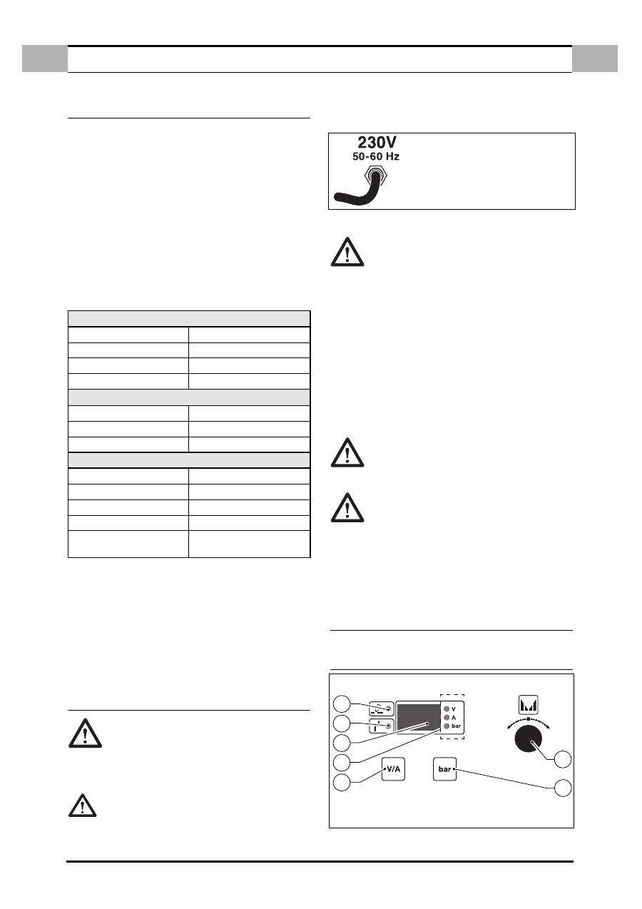
3.0 CONTROLS: LOCATION AND FUNCTION
3.1
FRONT PANEL
Figure 1.
PRIMARY
Single phase voltage
230V
Frequency
50 / 60 Hz
Effective consumption
11A
Maximum consumption
16A
SECONDARY
Voltage under no load
300V
Cutting current
10 ÷ 20A
Duty cycle
20A ÷ 50%
Protection class
IP 23
Insulation class
H
Weight
12 kg.
Dimensions
mm 410 x 180 x 310
Europeans Standards
EN 60974.1 - EN 60974.7
EN 60974.10
BEFORE INSERTING THE MAINS PLUG, IN
ORDER TO AVOID DAMAGE TO THE POWER
SOURCE, CHECK THAT THE MAINS CORRE-
SPONDS TO THE REQUIRED POWER SUPPLY.
3
6
7
4
1
2
5
USE INSTRUCTIONS
GB
(GB) 3
GB
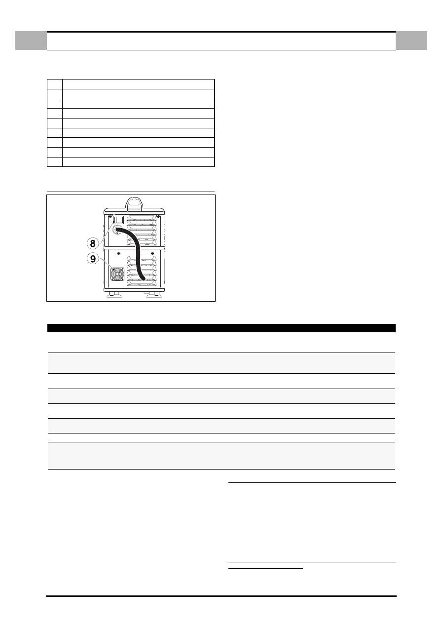
3.2
REAR PANEL
Figure 2.
3.3
COMMAND FUNCTION
1.
POWER OUTPUT INDICATOR
(
Ref. 1
- Fig. 1 page 2)
When the LED is on, the machine is ready for cutting
2.
ALARM INDICATOR
(
Ref. 2
- Fig. 1 page 2)
When the LED is on, this means that one of the alarms has triggered, at the
same time the display (
Ref. 3
- Fig. 1 page 2) shows the type of alarm,
according to the table below, with relevant operations to be performed in
order to reinstate the power source.
In this condition the power source does not supply current.
3.
DIGITAL INSTRUMENT
(
Ref. 3
- Fig. 1 page 2)
displays the power source current or the following values temporarily:
✔
Start message.
✔
Software version.
✔
Voltage on torch, pressing the key
(Ref. 5
- Fig. 1 page 2) .
✔
Air pressure, pressing the key (
Ref. 6
- Fig. 1 page 2) .
✔
Type of alarm (ALARMS), see table 1.
✔
Type of machine error (FAIL) , see table 2.
4.
DIGITAL INSTRUMENT FUNCTION
(
Ref. 4
- Fig. 1 page 2)
The LED on corresponds to the value shown on the display:
✔
Volt.
✔
Amper.
✔
Bar.
TABEL n° 1 - ALARMS
5.
CURRENT VOLTAGE KEY
Press the key (
Ref. 5
- Fig. 1 page 2) to display (
Ref. 3
- Fig. 1 page 2) the
voltage present on the torch.
The display of voltage is temporary.
6.
AIR FUNCTION KEY
Press the key (
Ref. 6
- Fig. 1 page 2) to activate the machine air system for
a fixed interval, with display of work pressure.
7.
CURRENT ADJUSTMENT KNOB
Used for adjusting the cutting current (
Ref. 3
- Fig. 1 page 2) .
8.
START SWITCH
(
Ref. 8
- Fig. 2 page 3)
This switch has 2 positions On (Green light on) or Off, for switching the
power source on or off.
9.
AIR FILTER
(
Ref. 9
- Fig. 2 page 3)
clean according to scheduled maintenance instructions.
4.0 USE INSTRUCTIONS
a.
Connect the power source in a dry place with suitable ventilation.
b.
Press the On switch (
Ref. 8
- Fig. 2 page 3) and wait for the power source
to start.
c.
Position the earth clamp on the piece to be cut, ensuring good electrical
contact.
d.
Select the cutting current with the knob (
Ref. 7
- Fig. 1 page 2) following
the data given in the table below.
e.
Approach the piece to be cut, press the torch button and begin cutting.
TO AVOID ELECTRODE AND NOZZLE WEAR, IT IS ADVISABLE NOT TO KEEP THE
PILOT ARC ACTIVATED IN THE AIR.
1
Power output indicator
2
Alarm indicator
3
Digital instrument
4
Digital instrument function (Volt - Amp. - Bar)
5
Voltage - current function key
6
Air function key
7
Adjustment knob
8
On switch
9
Filter
DISPLAY
MEANING
RESETTING
- - -
Insufficient input voltage. Line switch open or no
line.
When the alarm ceases.
If the alarm persists, contact the assistance cen-
tre.
CUP
The torch cap is not properly tightened (With
power source on).
Switch the power source off.
Tighten the cap correctly and restart the power
source.
HtA
Power converter overtemperature.
When the alarm ceases (When the internal tempe-
rature has fallen).
ThA
(Flashing)
Warning of approaching power converter over-
temperature (HtA).
When the alarm ceases (When the internal tempe-
rature has fallen).
CtA
Compressor overtemperature.
When the alarm ceases (When the internal tempe-
rature has fallen).
Air
Insufficient air pressure
(Less than 1.5 bar).
Contact the assistance centre.
ScA
Short circuit on output.
Switch the power source off and then on again.
LSF
Arc blows out.
Check wear of cap and electrode and replace if
necessary. If the alarm persists switch the power
source off and then on again. If the alarm occurs
again, call the assistance centre.
TORCH FUNCTION
GB
(GB) 4
GB
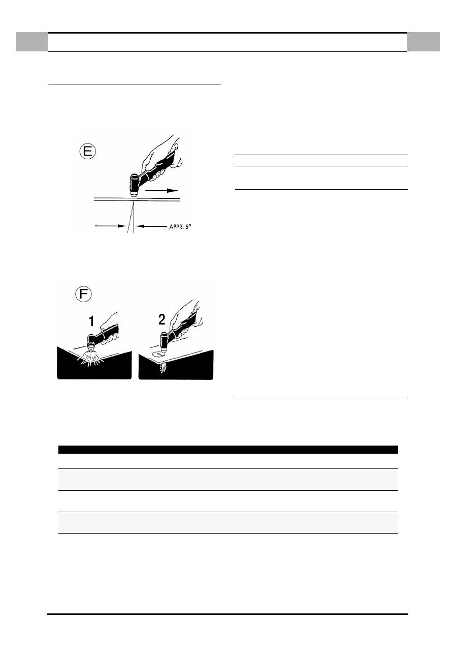
5.0 TORCH FUNCTION
Start to cut slowly, then increase the speed to obtain the desired cut quality . To
start a cut on the sheetmetal border, align the center of the torch to the sheetmetal
and press the start button: the arc cut will start on the border. Regulate the speed
to obtain a good cut. Air plasma will create a straight arc (stainless steel alumi-
num) or, a 5° arc
Fig. E
(Soft steel). The arc varies depending on speed, material
and thickness.
5.1
PERFORATION
In some cutting operations, it could be necessary to start the cut from a point dis-
tant from the border. The backfire from this operation could shorten the life of
torchs’ components. Therefore, it is suggested to do the job as fast as possible.
When doing a perforation (
Fig. F
).
Slightly incline the torch, so that backfire particles are blown away by the nozzle
(and by the operator) instead of bouncing back to the torch. Clean slag and
incrostations from the protection bush. Spraying or inmerging the protection
bush in an anti-slag substance, minimizes the quantity of incrostation that would
stick to it.
NOTE! The following suggestions should be taken in consideration for all cut-
ting operation.
a.
After completion of all cutting operation, wait 5 minutes before shutting off
the generator. It will give the fan time to cool and disperd the equipments’
heat.
b.
In order for components to last longer, don’t let the arc pilot “ON” longer
hen necessary.
c.
Handle torch components with care and protect them from damages.
d.
For material sostitution use only the safety tool.
READ FREQUENTLY OVER THE SAFETY PRECAUTIONS.
6.0
COMMON CUTTING DEFECTS.
Trouble shooting for arc cutting operations:
Insufficient penetration.
a.
Cutting speed too fast.
b.
Not enough power.
c.
Excessive material thickness.
d.
Torch components damaged or worn.
Main arc goes off.
a.
Cutting speed too slow.
b.
Nozzle too distant from workpiece.
Slag formation.
a.
Wrong gas pressure.
b.
Wrong cutting power.
Burned nozzle.
a.
Current too high.
b.
Nozzle damaged or loose.
c.
Nozzle touching the workpiece
d.
Excessive slag: low gas plasma pressure.
7.0 TROUBLESHOOTING
After starting, the power source may show operational errors on the display (
Ref.
3
- Fig. 1 page 2) , as shown in the table below. These errors can be remedied or
are irreversible.
Table n° 2 - FAIL -
DISPLAY
RESETTING
F14
Make sure that the cap is properly inserted.
Switch the power source off and then on again.
F10 - F11 - F12 - -F13
Switch the power source off and then on again.
If the "fail" persists call the assistance centre
and communicate the type of error.
F 15
Make sure that the torch button is
not pressed when switching the power source on.
Switch the power source off and then on again.
F20 - F30 - F51 - F52 - F53 - F54 -F55 - F56
Switch the power source off and then on again.
If the “fail” persists call the assistance centre
and report the type of error.
