Hach-Lange HQ440D Basic User Manual: instruction
Class: Equipment
Type:
Manual for Hach-Lange HQ440D Basic User Manual
DOC022.98.80116
HQ440d, HQ430d, HQ411d
06/2013, Edition 2
Basic User Manual
Basis-Bedienungsanleitung
Manuale utente di base
Manuel d'utilisation de base
Manual básico del usuario
Manual de operações básicas
Základní uživatelská příručka
Grundlæggende brugervejledning
Basisgebruikershandleiding
Podstawowa instrukcja obsługi
Grundläggande bruksanvisning
Peruskäyttöohje
Основно ръководство за потребителя
Alap felhasználói kézikönyv
Manual de bază al utilizatorului
Bendroji naudotojo instrukcija
Основное руководство пользователя
Temel Kullanıcı Kılavuzu
Základný návod na použitie
Osnovni uporabniški priročnik
Osnovni korisnički priručnik
Βασικό εγχειρίδιο χρήστη
Kokkuvõtlik kasutusjuhend

English...................................................................................................................................................................................................
3
Deutsch...............................................................................................................................................................................................16
Italiano.................................................................................................................................................................................................30
Français..............................................................................................................................................................................................44
Español...............................................................................................................................................................................................58
Português..........................................................................................................................................................................................72
Čeština................................................................................................................................................................................................86
Dansk.................................................................................................................................................................................................100
Nederlands......................................................................................................................................................................................113
Polski.................................................................................................................................................................................................128
Svenska............................................................................................................................................................................................142
Suomi.................................................................................................................................................................................................155
български.......................................................................................................................................................................................169
Magyar..............................................................................................................................................................................................183
Română............................................................................................................................................................................................197
lietuvių kalba...................................................................................................................................................................................211
Русский............................................................................................................................................................................................225
Türkçe................................................................................................................................................................................................240
Slovenský jazyk............................................................................................................................................................................253
Slovenski..........................................................................................................................................................................................267
Hrvatski.............................................................................................................................................................................................281
Ελληνικά...........................................................................................................................................................................................294
eesti keel..........................................................................................................................................................................................309
2
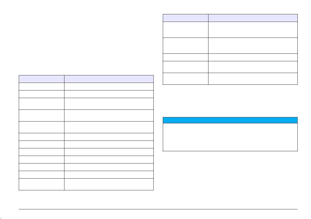
Table of contents
Specification Details
Specifications on page 3
Standard operation on page 10
Data export USB connection to PC or USB storage device
(limited to the storage device capacity). Transfer
General information on page 3
Data management on page 11
entire data log or as readings are taken.
Installation on page 5
Maintenance on page 13
Connections Integrated USB type A (for USB flash memory
User interface and navigation on page 7
Troubleshooting on page 14
device, printer, keyboard) and Integrated USB type B
Startup on page 9
(for PC)
Temperature correction Off, automatic and manual (parameter dependent)
Specifications
Measurement display
Continuous measurement, Interval or Press to Read
Specifications are subject to change without notice.
lock
mode. Averaging function for LDO probes.
Keyboard External PC keyboard connector with USB/DC
Specification Details
adapter
Dimensions 17.48 x 8.59 x 23.5 cm (6.88 x 3.38 x 9.25 in.)
Weight 750 g (1.65 lb) without batteries
General information
Meter enclosure IP54 with battery cover in place (resistant to intrusion
Revised editions are found on the manufacturer’s website.
of dust and water spray)
Power requirements
AA Alkaline or rechargeable Nickel Metal Hydride
Safety information
(internal)
(NiMH) batteries (4); battery life: up to 200 hours
N O T I C E
Power requirements
Class III, external power adapter: 100–240 VAC,
The manufacturer is not responsible for any damages due to misapplication or
(external)
50/60 Hz input; 4.5 to 7.5 VDC (7 VA) output
misuse of this product including, without limitation, direct, incidental and
consequential damages, and disclaims such damages to the full extent permitted
Meter protection class Class I
under applicable law. The user is solely responsible to identify critical application
Storage temperature –20 to +60 °C (–4 to +140 °F)
risks and install appropriate mechanisms to protect processes during a possible
equipment malfunction.
Operating temperature 5 to 45 °C (41 to 113 °F)
Please read this entire manual before unpacking, setting up or operating
Operating humidity 90% (non-condensing)
this equipment. Pay attention to all danger and caution statements.
Failure to do so could result in serious injury to the operator or damage
5-pin input connector M12 connector for IntelliCAL
™
probes
to the equipment.
Data memory (internal) 500 results
Make sure that the protection provided by this equipment is not impaired.
Do not use or install this equipment in any manner other than that
Data storage Automatic in Press to Read mode and Interval Mode.
Manual in Continuous Read Mode.
specified in this manual.
English 3
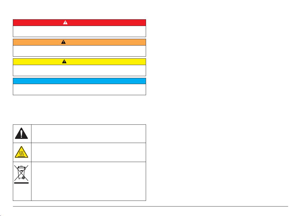
Use of hazard information
Product overview
The HQd series laboratory meters are used with digital IntelliCAL
™
D A N G E R
probes to measure various parameters in water. The meter automatically
Indicates a potentially or imminently hazardous situation which, if not avoided, will
recognizes the type of probe that is connected to the meter.
result in death or serious injury.
Measurement data can be stored and transferred to a printer, PC or USB
storage device (Refer to Figure 1).
W A R N I N G
The HQd series meters are available in 3 models:
Indicates a potentially or imminently hazardous situation which, if not avoided,
could result in death or serious injury.
•
HQ411d—pH/mV/ORP (Redox)
• HQ430d—Multi-parameter, single probe input
C A U T I O N
• HQ440d—Multi-parameter, dual probe inputs
Indicates a potentially hazardous situation that may result in minor or moderate
injury.
Features common to all models:
N O T I C E
• Automatic probe and parameter recognition
Indicates a situation which, if not avoided, may cause damage to the instrument.
• Instrument guided calibration procedures
Information that requires special emphasis.
• Calibration data stored in the probe
• Probe specific method settings for regulatory compliance and Good
Precautionary labels
Laboratory Practice (GLP)
• Security Options
Read all labels and tags attached to the instrument. Personal injury or
• Real-time data logging with a USB connection
damage to the instrument could occur if not observed. A symbol on the
instrument is referenced in the manual with a precautionary statement.
• USB connectivity to PC/printer/USB storage device/keyboard
• Bi-directional communication with PC-based systems with a virtual
This symbol, if noted on the instrument, references the instruction
serial port connection
manual for operation and/or safety information.
• Sample ID and Operator ID for data traceability
• Adjustable automatic shut-off
This symbol indicates that the marked item can be hot and should not
be touched without care.
Electrical equipment marked with this symbol may not be disposed of
in European public disposal systems after 12 August of 2005. In
conformity with European local and national regulations (EU Directive
2002/96/EC), European electrical equipment users must now return
old or end-of-life equipment to the Producer for disposal at no charge
to the user.
Note: For return for recycling, please contact the equipment producer or supplier
for instructions on how to return end-of-life equipment, producer-supplied
electrical accessories, and all auxiliary items for proper disposal.
4 English
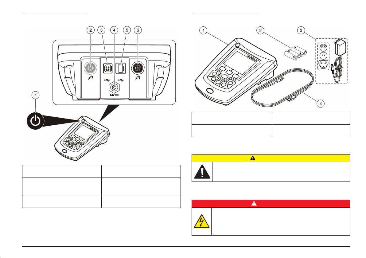
Figure 1 Product overview
Figure 2 Meter components
1 HQ440d, HQ430d or HQ411d
3 Universal power adapter
meter
2 AA batteries (pk/4) 4 USB cable (HQ440d, HQ430d
models only)
Installation
C A U T I O N
1 ON/OFF: turn on or turn off the
4 DC power connector
Multiple hazards. Only qualified personnel must conduct the tasks
meter
described in this section of the document.
2 Probe connection port (HQ440d
5 USB connector type A (for USB
model)
storage device, printer and
keyboard)
Connect to AC power
3 USB connector type B (for PC
6 Probe connection port
connections)
D A N G E R
Electrocution Hazard. AC power outlets in wet or potentially wet
Product components
locations MUST ALWAYS be provided with a Ground Fault Circuit
Interrupting (GFCI/GFI) circuit breaker. The AC-DC power adapter for
Refer to Figure 2 to make sure that all components have been received.
this product is not sealed and must not be used on wet benches or in
If any items are missing or damaged, contact the manufacturer or a
wet locations without GFCI protection.
sales representative immediately.
English 5
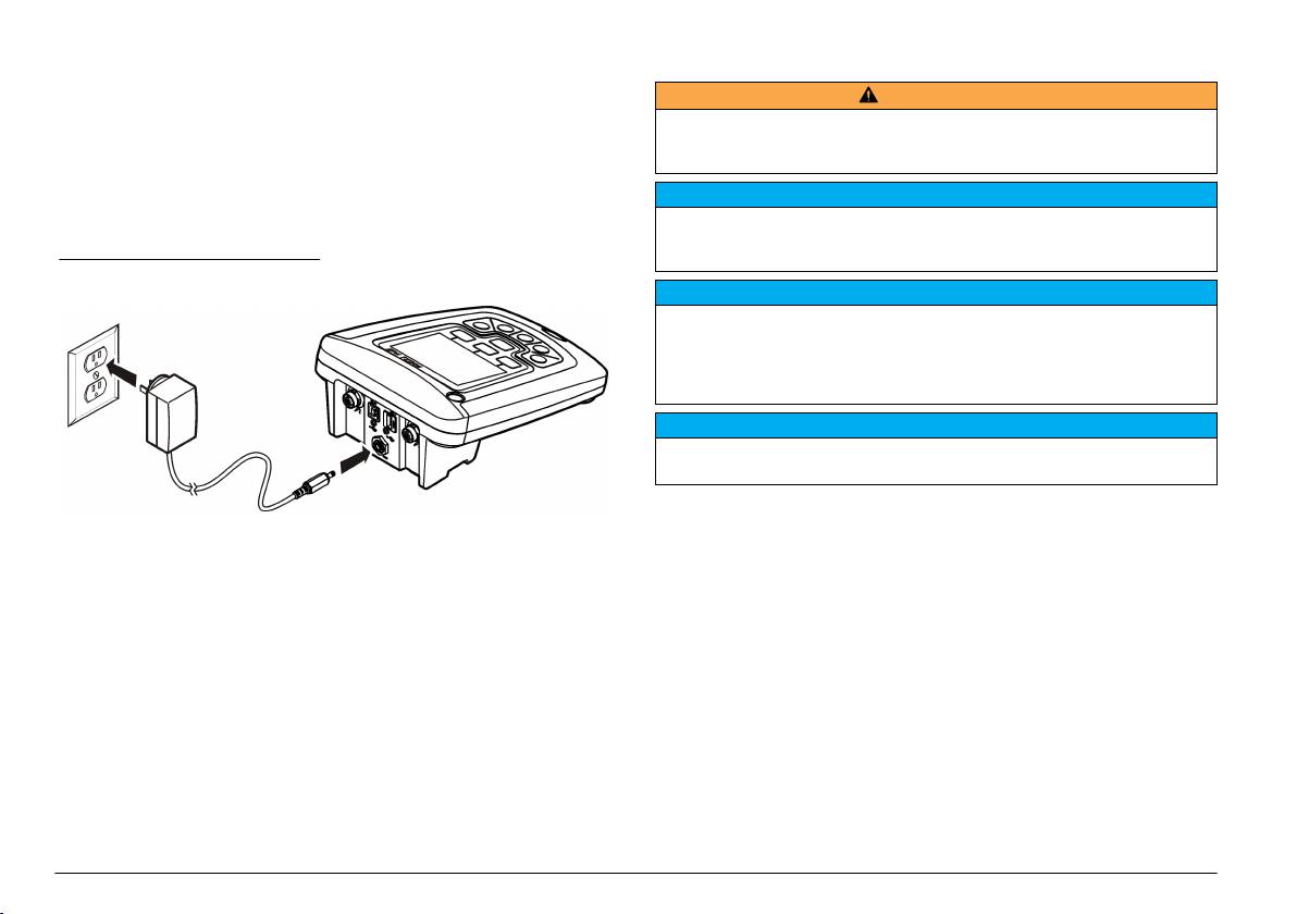
The meter can be powered by AC power with the universal power
Install the batteries
adapter.
W A R N I N G
1. Turn off the meter.
Explosion hazard. Incorrect battery installation can cause the release of explosive
2. Select the correct adapter plug for the power outlet from the adapter
gases. Be sure that the batteries are of the same approved chemical type and
kit (Figure 3).
are inserted in the correct orientation. Do not mix new and used batteries.
3. Connect the universal power adapter to the meter.
N O T I C E
4. Connect the universal power adapter to an AC receptacle.
The battery compartment is not waterproof. If the battery compartment becomes
5. Turn the meter on.
wet, remove and dry the batteries and dry the interior of the compartment. Check
the battery contacts for corrosion and clean them if necessary.
Figure 3 AC power connection
N O T I C E
When using nickel metal hydride (NiMH) batteries, the battery icon will not
indicate a full charge after freshly charged batteries have been inserted (NiMH
batteries are 1.2 V versus 1.5 V for alkaline batteries). Even though the icon does
not indicate complete charge, 2300 mAH NiMH batteries will achieve 90% of
instrument operation lifetime (before recharge) versus new alkaline batteries.
N O T I C E
To avoid potential damage to the meter from battery leakage, remove the meter
batteries prior to extended periods of non-use.
The meter can be powered with AA alkaline or rechargeable NiMH
batteries. To conserve battery life, the meter will power off after
5 minutes of inactivity. This time can be changed in the Display Options
menu.
For battery installation refer to Figure 4.
1. Loosen the three battery cover screws and remove the battery cover.
Note: Do not remove the screws from the battery cover.
2. Install 4 AA alkaline or 4 AA nickel metal hydride (NiMH) batteries.
Make sure that the batteries are installed in the correct polarity.
3. Replace the battery cover.
Note: Do not over-tighten the screws.
6 English
