Eneo GXC-1720M: instruction
Class: Video Audio Photo Equipment
Type: Action Camera
Manual for Eneo GXC-1720M

DE
EN
FR
PL
RU
Quick Installation Guide
Day&Night Network Camera, Full HD
GXC-1720M

Inhalt
Sicherheitshinweise .................................................................................................3
Lieferumfang .............................................................................................................3
Produktbeschreibung und Anschlüsse ................................................................4
1. Vorder- und Rückseite .......................................................................................4
2. Geräteseite ........................................................................................................5
Installation .................................................................................................................6
1. Überprüfen Sie die IP-Klasse Ihres PCs ............................................................6
2. Die UPnP-Pakete Ihres PCs installieren ............................................................6
3. Die Dienste Ihres PCs aktivieren .......................................................................7
4. Die statische IP-Adresse in der IP-Kamera einstellen. ......................................7
5. Die IP-Kamera durch “Netzwerkstandort” scannen ...........................................8
6. Die Steuerungs- und Betriebseinstellungen der IP-Kamera ändern. .................8
Diagramm der Verkabelung für die Alarmfunktion ............................................9
Hardware-Installation ............................................................................................ 10
Weitere Informationen ......................................................................................... 10
22
Sicherheitshinweise
Bitte beachten Sie auch die beiliegenden Sicherheitshinweise und lesen Sie
diese Anleitung vor Inbetriebnahme sorgfältig durch.
Wichtige Hinweise sind mit einem Achtungsymbol gekennzeichnet.
DE
DE
EN
EN
FR
FR
Lieferumfang
PL
PL
RU
RU
• Remote Viewer Software
• Netzgerät
• Betriebsanleitung
3
Produktbeschreibung und Anschlüsse
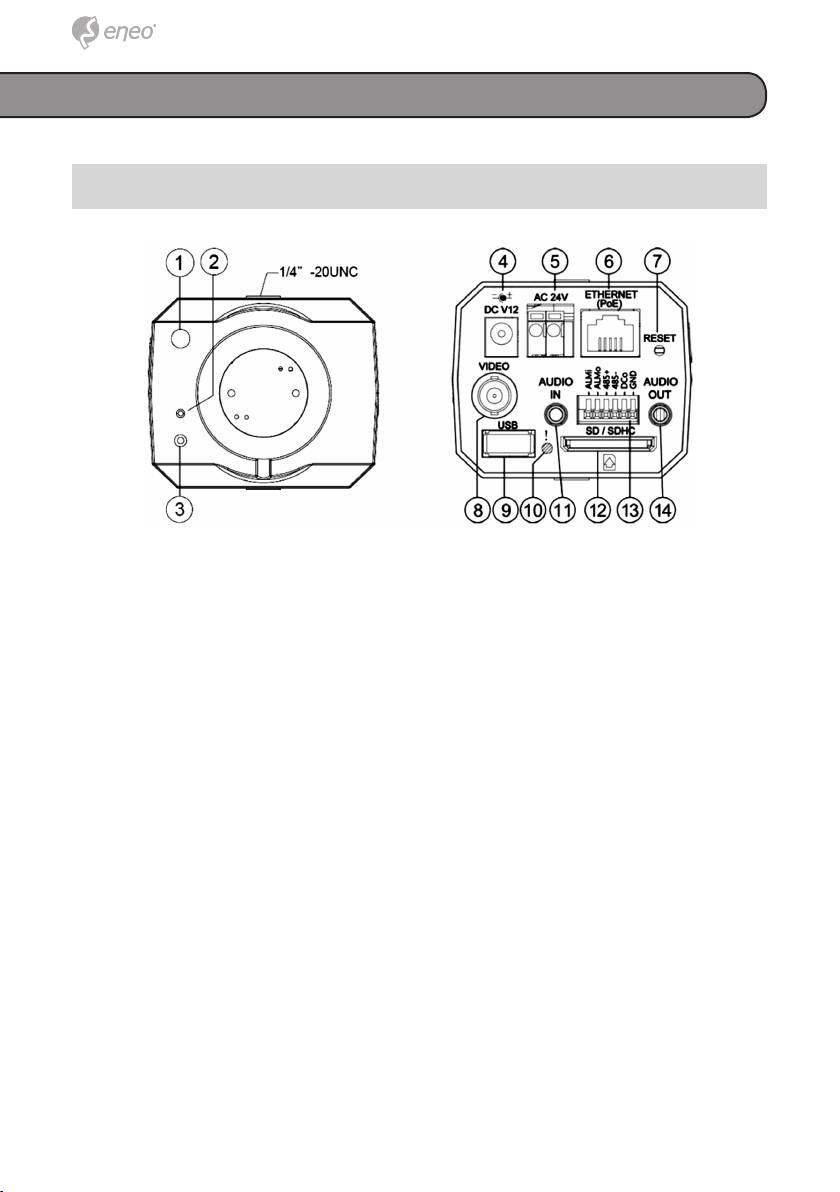
1. Vorder- und Rückseite
1. Lichtsensor: Misst die Lichtstärke in der unmittelbaren Umgebung der
Kamera und regelt die Irisblende, um die Lichtverhältnisse genauer
anzugeben.
2. MIKROFON: Die IP-Kamera besitzt eine zusätzliche Audiofunktion.
In der Vorderseite des Geräts ist ein Mikrofon eingebaut, mit dem der
Ton aufgenommen wird.
3. Betriebsanzeige (POWER): Zeigt den Betriebstatus des Geräts an.
4. Stecker-Eingangsanschluss: Ein 12V-Gleichstromeingang zum
Anschließen einer externen Stromquelle.
5. Stecker-Eingangsanschluss: Ein 24V-Wechselstromeingang zum
Anschließen einer externen Stromquelle.
6. ETHERNET 10/100-Anschluss: Ein Standard-RJ-45-Anschluss für
10/100 Mbps Ethernet-Netzwerke. PoE (Power over Ethernet)-Funktion:
Versorgung des Geräts mit Strom über das gleiche Kabel, das für die
Netzwerkverbindung verwendet wird.
7. RESET (Rücksetzen): Wiederherstellen der werkseitigen Standardein-
stellungen.
8. VIDEO OUT-Anschluss (Videoausgang): Über diesen Anschluss werden
die Compositve-Video-Signale des Geräts an einen Monitor übertragen.
9. USB-Port: Zum Anschließen eines USB-Gerätekabels für den Anschluss
der IP-Kamera an den USB-Port des PC’s.
10. LED-Anzeige: Die grüne Leuchtdiode zeigt an, dass das Gerät einge-
schaltet ist. Die SD-Karte kann nicht entfernt werden.
44
