Elinchrom D-LITE 2 IT: instruction
Class: Safety, Home Security
Type:
Manual for Elinchrom D-LITE 2 IT

OPERATION MANUAL
GEBRAUCHSANLEITUNG
MANUEL D’UTILISATION
MANUAL DE FUNCIONAMIENTO
MANUALE D’USO
РУКОВОДСТВО ПОЛЬЗОВАТЕЛЯ
D-Lite 4 it/D-Lite 2 it
English / Deutsch / Français / Español / Italiano / Русский Elinchrom LTD
D-Lite it 12.2009 (73002)

Table of contents
English
Introduction 2
Declaration of conformity, disposal and recycling, CE marking 3
Safety notice and precaution 4
Basic features & advanced programmable features 5
Before you start / On-Off switch and fuse 6
Control panel 7
Reset the unit 8
Modelling lamp features & setup 8
Digital power display 9
Photocell / Eye-Cell / Automatic Mode 10
Photocell / Eye-Cell / Manual Mode 11
EL-Skyport Transceiver Features & Setup 12
Flashtube Replacement / Error Management 13
Technical Data 14
EL-Skyport Transmitter Eco User Manual 15
Guarantee 121-122
P.S: Technical data subject to change.
The listed values are guide values which may vary due to tolerances in components used.
1

Introduction English
Dear Photographer,
Thank you for buying your D-Lite it compact flash unit.
All Elinchrom products are manufactured using the most advanced technology. Carefully selected
components are used to ensure the highest quality and the equipment is submitted to many controls
both during and after manufacture. We trust that it will give you many years of reliable service.
All D-Lite it flash units are manufactured for the studio and location use of professional photogra-
phers. Only by observance of the information given, you can secure your warranty, prevent possible
damage and increase the life of this equipment.
D-Lite 2 it / D-Lite 4 it Compact Flash
The quality of light and exceptional performance is the result of long research, application of de-
manding principles, the long experience of ELINCHROM in lighting products for the studio and the
utilisation of the latest technology in this area.
Totally integrated to the range of ELINCHROM flashes, the D-Lite 2 it - D-Lite 4 it units maintain
the traditional look and function that is ELINCHROM.
The controls provide continuously variable adjustment of the flash power with precision over
5 f-stop, from full power 1/1 to 1/16 th, & modelling lamp with prop/min/max/off mode.
FCC Class B Compliance Statement
This equipement has been tested and found to comply with the limits for a class B digital device, pursuant to Part
15 of the FCC Rules and meets all requirements of the Canadian Interference-Causing Equipement Regulations.
These limits are designed to provide reasonable protection against harmful interference in a residential installation.
This equipement generates, uses, and can radiate radio frequency energy and, if not installed and used in
accordance with the instruction manual, may cause harmful interference to radio communications. However,
there is no guarantee that interference will not occur in a particular installation. If this equipement does not cause
harmful interferences to radio or television reception, which can be determined by turning the equipement off
and on, the user is encouraged to correct the interferences by one or more of the following measures:
- Reorient or relocate the receiving antenna.
- Increase the separation between the equipement and receiver.
- Connect the equipement into an outlet on a circuit different from that to which the receiver is connected.
- Consult the dealer or an experienced radio/TV technician for help.
Elinchrom LTD is not responsible for any radio or television interference caused by unauthorised modifications
of this equipement or the substitution or attachment of connecting cables and equipement other than those
specified by Elinchrom LTD The correction of interference caused by such unauthorised modification, substitution
or attachment will be the responsibility of the user.
2
Declaration of conformit English
This device complies with Part 15 of the FCC Rules. Operation is subject to the following two
conditions:
1. This device may not cause harmful interference.
2. This device must accept any interference received, including interference that may cause
undesired operation.
Product name: Professional Studio Flash unit
Trade name: ELINCHROM
Model number(s): D-Lite 2 it / D-Lite 4 it
Name of responsible party: Elinchrom LTD
Av. De Longemalle 11
1020 Renens / Switzerland
Phone : +41 21 637 26 77
Fax: +41 21 637 26 81
Elinchrom LTD declares that the equipement bearing the trade name and model number speci-
fied above was tested conforming to the applicable FCC rules, and that all the necessary steps
have been taken and are in force to assure that the production units of the same equipement will
continue to comply with the Comissions requirements.
Disposal and recycling
This device has been manufactured to the highest possible degree from materials
which can be recycled or disposed of in a manner that is not enviromentally
damaging. The device may be taken back after use to be recycled, provided that is
returned in a condition that is the result of normal use. Any components not reclaimed will be
disposed of in an environmentally acceptable manner.
If you have any questions on disposal, please contact your local supplier or your local
ELINCHROM agent (check our website for a list of all ELINCHROM agents world wide).
CE marking
The shipped version of this device complies with the requirements of ECC directives
89/336/ECC «Electromagnetic compatibility» and 73/23/ECC «Low voltage directive».
CE Statements for EL-Skyport
This device has been tested and found to comply with the requirements set up in the council
directive on the approximation of the law of member states relating to EMC Directive 89/336/
EEC, low Voltage Directive 73/23/EEC and R&TTE Directive 99/5/EC.
Notational Conventions
The meaning of the symbols and fonts used in this manual are as follows:
Pay particular attention to text marked with this symbol.
Failure to observe this warning endangers your life, destroys the device, or may
damage other equipement.
!
3

Safety Note English
According to safety regulations, we draw your attention to the fact that these
electronic flash units are not designed for use outdoors, in damp or dusty conditions and should
not be used after being exposed to sudden temperature changes causing condensation. They
must always be connected to an earthed (grounded) mains supply.
On no account should any object be inserted into the ventilation holes.
The units may retain an internal charge for a considerable time even though disconnected from
the power supply.
• Do not use without permission in restricted areas (like hospitals, etc.).
• Do not use in explosive environnements.
Flash tubes and modelling lamps
• Flash tubes and modelling lamps in use are very hot!
• Never touch a ash tube or lamp before the unit has cooled down and is disconnected from
the mains (min 30mn).
• Do not re ashes from short distance (less than 1m) directed at a person and avoid looking
directly into the flashlight!
• Keep a min. 1m distance from any ammable materials.
• Keep generally distance to other operating units.
Transport
• Transport the ash unit with care, either in its original packaging or other corresponding
packaging fit to protect it against knocks and jolts.
• Transport only in complete discharged conditions. Wait a minimum of 30 minutes after
disconnecting from the mains supply before packaging and transportation.
• Never drop the ash unit (danger of ashtube breakage)
Power cable
To guarantee safe operation, use the cable supplied.
• The cable has to be HAR-certied or VDE-certied. The mark HAR or VDE will appear on the
outer sheath.
• The cable set must be selected according to the rated current for your ash unit.
• Do not use a multiple adapter to connect one or more ash units per single mains socket.
• Flash systems store electrical energy in capacitors by applying high voltage.
• For your safety, never open or disassemble your ashes.
• Only an authorised service engineer should open or attempt to repair the units.
• Internal defect charge capacitors may explode whilst the unit is in use, never
!
switch on a working flash unit, once it has been found to be faulty.
• Do not connect on the ash unit to mains supply without mounted modelling
Notational Conventions
lamp or flash tube due to high voltage at the contacts!
The meaning of the symbols and fonts used in this manual are as follows:
Life Danger!
Pay particular attention to text marked with this symbol.
Failure to observe this warning endangers your life, destroys the device, or may
damage other equipement.
4

Included basic features English
The following basic features are easy to access and they are similar to previous Elinchrom compact
flashes.
• Flash power up and down buttons
• Modelling lamp mode button (prop / min /max / off)
• Photocell on / off button
• Ready charge beep on / off button
• Test-ash button
• 3.5 mm synchronisation socket
• NEW EL-Skyport Wireless Triggering. Note: To function the integrated
Receiver requires the optional EL-Skyport Transmitter.
Additional advanced programmable features
All the new features and functions can be customised.
Please read carefully how to configure the new features.
“Eye-Cell” automatic & manual mode
Some cameras may release before the main-flash, several pre-flashes to avoid the red eye
effect. In this case a normal photocell would respond and release a flash with the first pre-flash
of the camera. To avoid incorrect synchronisation the intelligent Elinchrom Eye-Cell detects
camera pre-flashes. The Eye-Cell function can be activated in “Automatic Mode” or in “Manual
Mode”, even configuring LED pre-flashes. (Only for advanced users, read carefully the instruc-
tions before changing any parameters).
EL-Skyport wireless triggering & remote control
D-Lite it can be triggered using EL-Skyport Transmitter.
“Group” and “ Channel Frequency” settings can be customised on each D-Lite it unit.
Power and modelling lamp steps setup
Normally flash power adjustments are in 1/10th steps per touch. While modelling lamp can be
operated in (prop / min / max /off) modes.
Temperature controlled FAN management
The cooling fan switches ON automatically if the unit temperature increases. The microprocessor
controls the unit temperature and the fan. If the ventilation is blocked or the fan does not work,
the display shows E8.
5
Before you start ! English
The D-Lite it (Multivoltage) units are adapted for operation on 90 - 260V/50 - 60Hz. Before con-
necting for the first time, check to make sure that your Modelling Lamp coincides with the voltage.
They must always be connected to an earthed ( grounded) mains supply. All
D-Lite it units have a
bayonet mount and locking ring fitting, for fixing all Elinchrom and Prolinca accessories.
The Reflector Bayonet supports Reflectors and Softboxes up to 1.5 kg, e.g. Rotalux 100 x 100 cm .
Mount the unit securely to a suitable stand or support.
Remove the black protective cover. DO NOT operate the unit without first removing the black
protective cover.
Operating instructions
1.Check that the modelling lamp voltage is correct.
2.Check that the mains switch (2) is in the position OFF ("O" position).
3.Insert the mains cable into the MAINS INLET (1) and connect this to a FULLY EARTHED OUTLET
4.Using the mains SWITCH (2), switch the unit ON ("I" position).
5.Connect the synchro cord to its socket (5).
6.Select the power with the touch pad (10)
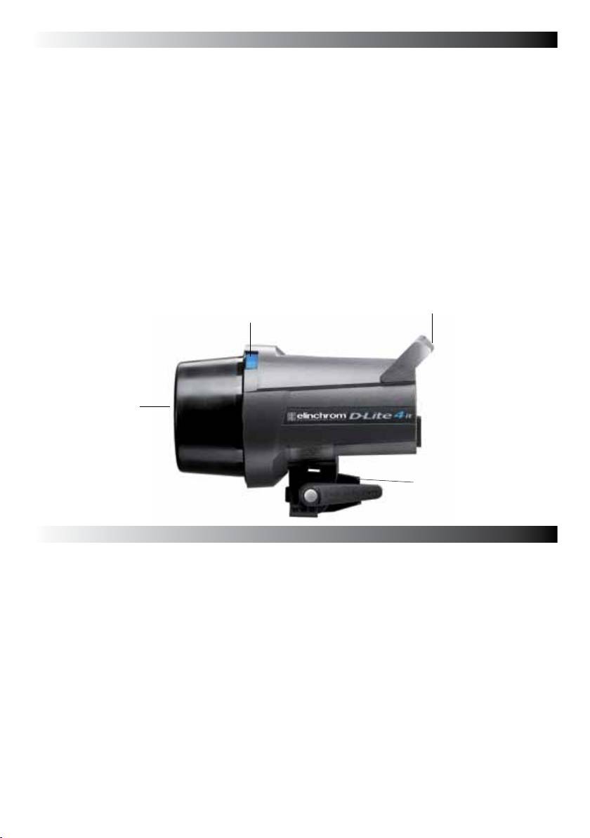
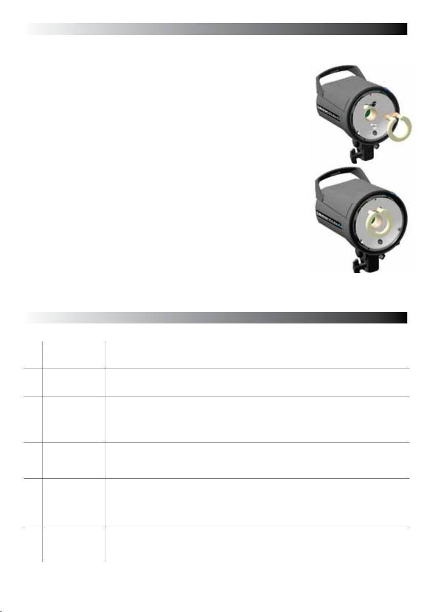
Handle with
spare fuse
(A) Locking ring
(B) Protective cover
(26124)
(C) Tilthead with locking
umbrella holder
Switch and fuse
Mains supply
Use only the Elinchrom mains cord. Switch off the unit before the mains cord is connected to
the mains plug.
Mains fuse
Standard type 5 x 20 mm, use only tempered fuse 8 AT (code 19022) for
D-Lite it
Note: Before exchanging a blown fuse, switch off the unit and remove the mains cable. Open
the little drawer in the mains plug with a screwdriver and replace the fuse with the spare fuse,
which is placed in its support in this drawer. (N.B. Please don’t forget to check the correct value
of the fuse!).
Fuse for modelling light
Fast type 5 x 20mm, 2.5 AF
Switch off the unit and replace the blown fuse with a new one of the correct value.
The fastblow fuse will protect the triac of the modelling lamp circuit, the lamp and therefore
the flash tube.
6
Control panel English
13
11
3
6
4
10
9
7
8
5
1
2
15
12
14
16
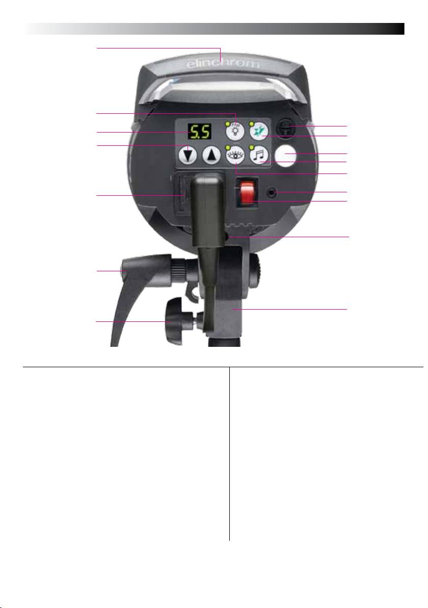
Overview of controls
1. Mains inlet socket includes the mains fuse
11. Modelling lamp mode button (prop/min/
(slow blow)
max/off/)
2. Mains on/off switch
12. Tilt head with extra umbrella fitting
3. Modelling lamp fuse
13. Handle with support for spare fuse
4. Open flash / Test button
14. Standard stand socket 5/8 inch
5. Synch socket / 3.5 mm jack / low 5V sync
15. Centred umbrella tube for EL Umbrellas –
voltage
7 mm diameter
6. Digital multi display and charge / discharge
16. Knurled clamp screw
indicator*
7. Charge Ready Beep on/off
8. Eye-Cell on/off – programmable*
9. Eye-Cell receptor
10. Power up & down buttons and scroll /pro
gram buttons for advanced features setup*
*The touches on this display are multifunctional to program / scroll the advanced features and to
setup the integrated EL-Skyport Transceiver. For programming please read carefully the following
pages!
7

Programmable features - Reset English
How to „Reset“ the D-Lite it
In case you need to „RESET“ the D-Lite it to the manufacturer settings please follow the steps below:
1. Switch the unit “off“
2. Press both flash power up / down buttons (10) at the same time and switch the unit on
3. The Digital LED multi display (6) flashes in fast mode
4. Do not continue to press the buttons, the resetting procedure is completed
Modelling lamp features & setup
Modelling lamps and fuses for 110 V & 230 V
Unit Modelling lamp 110V Modelling lamp 230V Socket Fuse
D-Lite 2 it 100W / 23006 100W / 23002 E27 2.5AF / 19035
D-Lite 4 it 100W / 23006 100W / 23002 E27 2.5AF / 19035
* Do not use energy saving lamps
Modelling lamp modes
>
Setting: • Press “Modelling” button to set Modelling lamp ON to proportional mode, max.
mode, min. mode, or OFF
• Press “Modelling” up or down button to set Modelling lamp to free mode, press
“Free/Prop” to switch Modelling lamp OFF.
> LED Indication: • LED is on: only in proportional mode.
• LED is off: in min. / max. / off mode.
• Please use only original ELINCHROM modelling lamps with a maximum power
!
of 100W ( effective 150W).
8
Digital multi-display English
The flash / modelling lamp power is displayed in f-stop compatible formats from 2.0 – 6.0 for
D-Lite it 4 / 400 ws
. The flash power difference from (e.g.) 5.0 – 6.0 is 1f-stop.
The power range is 5 f-stops, variable in 1/10th intervals. During charging or discharging, the
display «flashes». In case of overheating or malfunction, the display shows “E” for error followed
by the error code number.
Display 2.0 3.0 4.0 5.0 6.0
Joules / Ws 25 50 100 200 400
Note: The «D-Lite 2 it - D-Lite 4 it» units have an integrated discharge system, protected by a
thermal switch. To avoid overheating, discharge manually with the «test» button if you want to
decrease the power for more than 2f-stops.
Sychronisation socket
Standard socket with 3.5 mm mini-jack (5).
5
N.B. Do not link ELINCHROM units by cable to other manufacturers sync. outlets.
ELINCHROM uses low voltage (5 V) for security reasons.
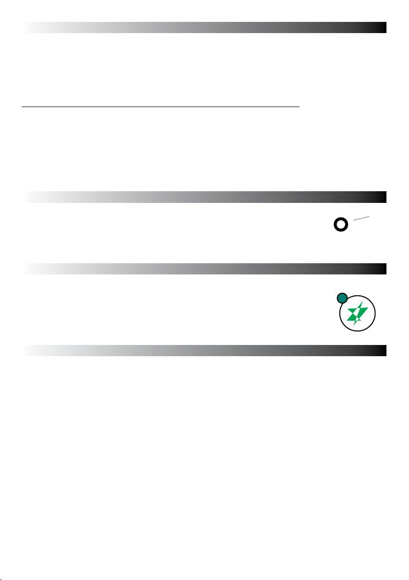
Sync
Open flash «test»
Having pressed the touch pad to release a flash, the green «READY» light
Test and Ready (4)
will appear again once the unit is recharged. If the green light does not
appear the charge system could be defective.
Please contact an authorized Elinchrom service centre.
Eye-Cell – advanced photocell sensor
The standard photocell can be remotely triggered by another flash unit!
The D-Lite it photocell is specially designed to work in studio light conditions
Direct light or other strong light sources may reduce the sensitivity of the cell.
9

Eye-CELL Setup English
Intelligent Photocell-Sensor
The Eye-Cell offers new features and can detect camera pre-flashes (anti red eye effect).
To customise the pre-flash settings, please follow the instructions in paragraph 3.
Eye-Cell Functions
1. Standard Photocell mode
2. Eye-Cell pre-flash mode
3. Setup number of pre-flashes manually or set to automatic detection
4. Setup pre-flash timings! Only for advanced users!
1. Using the Standard Photocell Mode
Push “Cell” button, for less than 0.5 seconds to switch on/off the standard Photocell sensor.
LED Indication:
Cell LED is ON: Active photocell.
Cell LED is OFF: Inactive photocell.
If active, the Photocell sensor will trigger the flash unit with any recognized flash impulse.
2. Eye-Cell Pre-Flash Mode
(This is only activation, not the setup. To Setup, follow step 3)
Press the Cell button for approx. 1 second; the status LED starts flashing.
LED Indication:
Cell LED flashes in slow intervals; the Eye-Cell pre-flash mode is activated.
Cell LED is OFF; the Eye-Cell pre-flash mode is inactive.
Function:
In active mode the unit ignores up to 6 anti-red-eye flashes and synchronizes / triggers only with
the last main flash. This is useful where if the camera anti-red eye pre-flashes can’t be switched
off.
3. Automatic Eye-Cell Pre-Flash Setup “c.0”
Press the Cell button for 4 seconds until display shows “c.X” for automatic setup.
(“X” is the number of pre-flashes including main flash from 1 up to 7)
Scroll with the “Flash-Power” up and down button to “c.0”
Now use the camera-on flash and release a test exposure. The camera will release several anti-
red eye flashes (if activated). The D-Lite it Eye-Cell detects the number of flashes the camera
released and stores the value automatically, and switches back to Eye-Cell Pre-flash mode.
Ready to use.
If the cell button was pressed down for 6 seconds the “Setup Pre-Flash Timeframe” is
!
activated and the display shows t.4 or b.1 (standard settings). Do not change these values; this
would deactivate the “Automatic Eye-Cell Mode”! Wait a few seconds, the unit switches back to
the standard mode and the display shows the flash power settings. Should the t.4 or b.1 values
have been changed, please set the “Setup Pre-Flash Timeframe” back to standard settings as
descript at paragraph 4.
10

4. Manual Eye-Cell Pre-Flash Setup
A. Press Cell button approx. 4 seconds until display shows “c.X”.
(“X” is the number of settable pre-flashes plus the main flash from 1 up to 7)
B. With “Flash-Power” up and down button, set the number of pre-flashes incl. mainflash.
C. The display switches back to normal mode after approx. 4 seconds if no button is pressed.
The settings are automatically stored.
D. Cell LED flashes in fast intervals if the Eye-Cell pre-flash mode is active.
> Recall The Eye-Cell Settings:
If you want to recall the actual Eye-Cell pre-flash setting, repeat the steps A.
If you want to control the actual Eye-Cell pre-flash setting, repeat the steps A to D.
5. Setup Pre-Flash Timeframe (only for advanced users)
Change manufacturer settings only in case of problems with the auto-detection
of your camera pre-flashes.
!
> Setting:
• Press Cell button for more than 6 seconds until display shows “t.X” (“X” is the value from 1 to 8)
• Use the Cell button to toggle between “t.X” and “b.X” settings.
• Use the “Flash-Power” up and down buttons to change the values.
• The display switches back to normal mode after approx. 4 seconds if no button is pressed.
The settings are automatically stored.
• Standard settings are:
---> t.4 (t. is the time window of all released anti red-eye flashes incl. the main flash).
---> b.1 (b. is the minimum time delay between two anti red-eye flashes incl. the main flash).
Pre-Flash Timeframe Setting “t.X
t. is the time window of all released anti red-eye flashes incl. the mainflash. Change setting only
when the pre-flash procedure is longer than the manufacturer settings.
Set the value t. between 1 and 8 to ensure that all pre-flashes including the main flash are inside
the time frame.
Value t 1 2 3 4 5 6 7 8
Time: [seconds] 1 2 3 4 5 6 7 8
Pre-Flash Block Time Setting “b.X”: (Only For LED Anti Red-Eye Cameras)
Pre-Flash Block -Time: set the minimum delay between each pre-flash.
Chose values between 0 and 7.
Value b 0 1 2 3 4 5 6 7
Time: [miliseconds] 0 2 4 6 8 10 12 14
11

Integrated EL- Skyport Transceiver For Wireless Triggering – Setup
English
The EL-Skyport on / off, Group, Frequency Channel can be customised.
EL-Skyport on / off
Press the flash power up-down buttons together to enter into the “Advanced Feature Setup”
Display shows Change settings with the flash power up-down buttons
r.0 EL-Skyport off
r.1 EL- Skyport on
r.2 EL-Skyport speed mode (only available with EL-Skyport Speed /
ECO)
After 3 to 4 seconds the settings are saved automatically and the display shows the flash power
setting.
Group Settings
Press the flash power up-down buttons together to enter into the “Advanced Feature Setup”.
Then, scroll to G.1 using the Prop/Free button.
Display shows Select Group with the flash power up-down buttons
G.1 Group 1 (standard setting)
G.2 Group 2
G.3 Group 3
G.4 Group 4
After 3 to 4 seconds the settings are saved automatically and the display shows the flash power
setting.
Frequency Channel Settings
Press the flash power up-down buttons together to enter into the “Advanced Feature Setup”.
Then, scroll to F.1 using the Prop/Free button (only use in cases of interference with
other systems).
Display shows Change the Channel with the flash power up-down buttons
F.1 to F.4 Select Frequency Channel from 1 – 4.
Note: The transmitter must have the same Frequency Channel
setting. Standard setting is Frequency Channel 1.
After 3 to 4 seconds the settings are saved automatically and the display shows the flash power
setting.
12
Flashtube replacement English
If the unit does not flash but the ON/OFF switch indicates that there is power, it could be that the
flash tube needs replacing. Flash tubes have a long life with average use,
but multiflashing in long sequences can cause overheating of the electrodes
leading to premature ageing, or perhaps the flastube is broken or cracked.
To replace the flash tube:
1. Switch off the mains switch
2. Remove the mains cable
3. Take the unit from its stand or lay it horizontally on a rigid surface. It will
need to be held firmly whilst removing and replacing the tube.
4. Allow the flash tube and modelling lamp to cool for several minutes. They
may be very hot.
5. Carefully remove and store the modelling lamp.
6. Use a protective glove to remove the flashtube:
A – Pull the flash tube firmly out of the terminals
B – If the tube is broken, use security gloves. Avoid cutting yourself!
C - If the tube is broken, never touch the metal electrodes and ensure
that the unit is disconnected from the mains and discharged, wait min.
30 minutes! Use an insulated tool to pull out the electrodes.
7. Take the new flash tube. A glove or "plastic protection" MUST BE USED.
Contact with your fingers on the glas, will cause dark markings on the tube
when it is used.
8. Check that the tube is correctly aligned (central) and that the trigger contact
is gripping the tube.
9. Re-connect and test the unit as usual.
Error Management
Error Fault Description
Overvoltage
Switch unit OFF, wait 2 minutes and switch unit ON again. If the error shows
E1
detected
up again the unit requires a check up at the Elinchrom service centre
Wait until the unit has cooled down. The unit will switch back to normal opera-
E2 Overheating
tion as soon as temperature decreases to normal working level.
The Unit has detected a time out in the ADF mode. Switch the unit OFF, wait
Auto dump
2 minutes and switch the unit ON again; use the Test release button for power
E3
function fault
reduction. If the error shows up again the unit requires a check up at the
Elinchrom service centre.
Unit has detected a time out during recharging. Switch unit OFF, wait
E4 Charge fault
2 minutes and switch unit ON again. If the error shows up again the unit re-
quires a check up at the Elinchrom service centre.
Unit has detected a mains supply fault. Check your mains cord and mains
Mains supply
installation sockets. Switch unit OFF, wait 2 minutes and switch unit ON again.
E5
fault
If the error shows up again the unit requires a check up at the Elinchrom
service centre.
Unit has detected a FAN management problem due to overheating. Wait until
Fan manage-
E8
the unit has cooled down. Check if the FAN is blocked. If the error shows up
ment fault
again the unit requires a check up at the Elinchrom service centre.
13

Technical data D-Lite 2 it D-Lite 4 it
Ws / Joule J(Ws) 200 400
F-Stop
45.3 64.3
Power range f-stop
5 5
Power range Ws
J(Ws) 12-200 25-400
Power adjustment
f-stops 1/10 f-stops
Recycling time, min. / max. (230 V)
s 0.2 / 0.6 0.35 / 1.2
Recycling time, min. / max. (115 V) s 0.2 / 0.8 0.35 / 1.6
Flash duration s 1/1200 1/800
Power stability 0.5%
Auto Power Dumping Applies power settings automatically
Voltage V Multi voltage, 90-260 V
Modelling lamp 100W/E27 - effective 150W
Modelling lamp setting Proportional, full, low, off
Flashtube Plug-in, user replaceable
Umbrella fiting Centred tub, for EL-umbrellas ø 7mm
Sync voltage 5V compatibility with digital cameras
Power consumption 115 V / 60 hz
160 W / 850 VA
no fl ash / recycling
Power consumption 230 V / 50 hz
140 W / 1200 VA
no fl ash / recycling
EL-Skyport Integrated transceiver, 4 Groups, 4 Frequencies
Dimensions cm 26 x 19 x 14
Weight kg 1.3 1.5
DL-it Code 20483.1 20484.1
Radio interference suppressiv CE-IEC 491 EN 60 555 - EN 61 000 - 4 - 2/3/4/5
Tolerances and specifications conforming to IEC and CE standards. Technical data subject
to change without notice.
14
English
Transmitter Eco
19349
User Manual
Contents :
Features 16
Battery Installation 16
Hot-shoe connector 16
Operating Instructions 16
Frequency Channel 17
EL-Skyport ECO Features 18
EL-Skyport Modules 19
Troubleshooting 19
CE Statements 19
FCC Compliance and
Advisory Statement 20
Disposal and recycling 20
English
EL-Skyport Transmitter Eco / 19349
Operating instructions :
2.4 GHz digital wireless Flash Trigger Transmitter
Features
EL-Skyport Transmitter Eco is designed with the latest 2.4 GHz Digital Wireless Technology.
• SLR Camera Sync speeds: SPEED mode up to
• New extra features; congure EL-Skyport with the
1/250 s, STANDARD mode 1/160 - 1/200 s.
new EL-Skyport PC/MAC software 3.0.
• 4 frequency channels.
• The SPEED function is available for Ranger Quadra AS,
• 40 Bit security encryption.
BXRi 250 / 500 and D-Lite it and all other units, when
• Up to 50 m range indoors for standard mode and
used with the EL-Skyport Universal Speed.
up to 30 m in speed mode.
• Up to 80 m range outdoors for standard mode
You will appreciate the convenience of this new easy to
and up to 40 m in speed mode.
use and powerful wireless device.
• Battery life up to 6 Months - over 30’000 ashes.
• Test trigger button and feature button.
Note: Shutter speed and distance range is inuenced by
interference from other 2.4 GHz electronic equipment.
• Integrated Hot-shoe (middle contact).
and reections of ceilings, walls, oors, furniture, metall,
• Two ash modes, standard and speed.
trees and humidiy in woods etc.
• Standard mode full compatible with previous EL-Skyport
versions.
For best performance the Transmitter and Receiver should
• Status LED for EL-Skyport mode and battery status.
have direct sight, without any walls or objects in between.
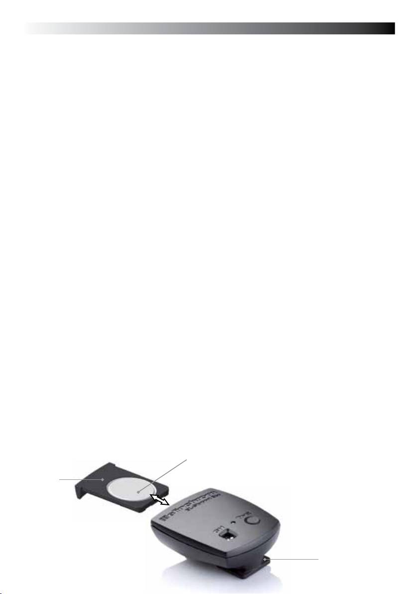
Battery Installation
1. Pull the battery drawer out carefully
2. Place the Lithium battery, see Fig. 1 for polarity
3. Close the battery drawer
! CAUTION:
• Ensure correct polarity / minus pole on top
• Use Lithium Battery only CR2430 3.0V 19372
• Remove battery if the EL-Skyport Transmitter is not to be used for some time
• Never short-circuit battery poles
• Avoid direct sunlight or temperatures above 45°C. The battery may explode!
Hot-shoe Connector
The new Hot-shoe connector with middle contact synchronisation is designed to t digital and analogue
cameras with maximum sync output of 3 V (the middle contact is the positive pole).
Operating Instructions
Fig. 1
Battery (19372)
Minus pole on top
Battery drawer
Hot-Shoe
16
English
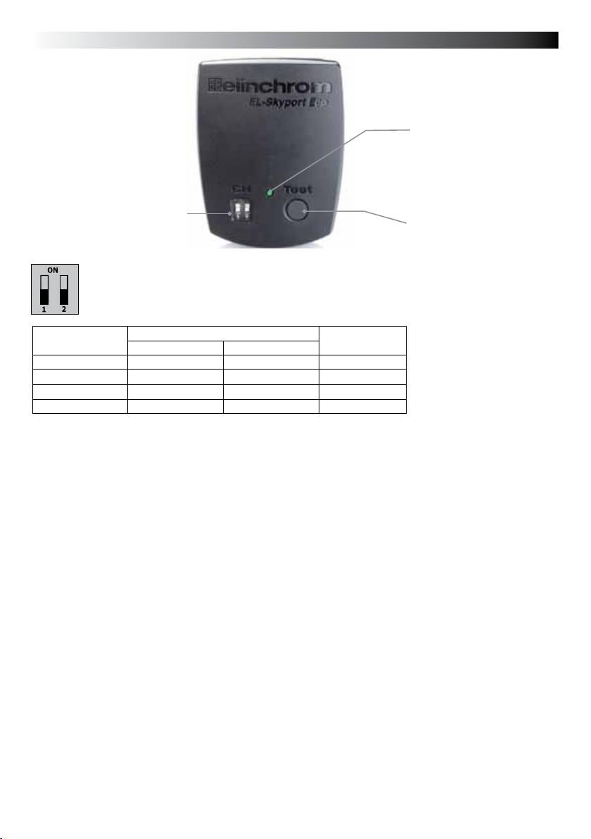
Fig. 2
Status LED
Four Frequency
channel selectors
Flash Test
Frequency Channel
Note:
Transmitter and the corresponding Transceiver RX the Universal Receiver or the EL units with
integrated EL-Skyport Receiver must have the same frequency channel settings!
Frequency
Slide Button conguration Frequency
Channel
1 2
/ Mhz
1 (default) Off Off 2456
2 On Off 2458
3 Off On 2460
4 On On 2462
EL-Skyport Sync Speed & Standard Mode
The SPEED function is available for Ranger Quadra AS, BXRi 250 / 500 und D-Lite it and all other units,
when used with the EL-Skyport Universal Speed.
Select “Speed” sync mode
Synchronises SLR cameras up to 1/250 s, or compact digital cameras up to 1/2850 s
- Press test push button one time to switch module on.
- Press test push button for minimum 5 seconds until the STATUS LED ashes two times.
- Release test push button.
- Now the EL-Skyport Transmitter Eco works in “SPEED” mode (r.2 mode).
Select “Standard” triggering mode
Synchronises SLR cameras up to 1/200 s, or compact digital cameras up to 1/1600 s
- Press test push button one time to switch module on..
- Press test push button for minimum 5 seconds until the STATUS LED ashes one time.
- Release test push button.
- Now the EL-Skyport Eco works in “STANDARD” mode.
EL-Skyport Module Conguration:
Only possible with EL-Skyport PC / MAC software v3.0 and higher.
- Power-Save Timer, individual programmable or disabled.
- Trigger delay is programmable from 250 microsecondes (1/4000 s) up to 15 s.
- Download the FREE EL-Skyport Software 3.0 from www.elinchrom.com
17

English
SET Cong Mode:
(to congure included features only with MAC°/ PC° EL-Skyport Software V. 3.0)
- Switch the module OFF // remove battery..
- Hold the Test button down whilst you insert the battery..
- Keep test push button pressed until STATUS LED is ON.
Please check also EL-Skyport PC/MAC software 3.0 for changing Transmitter setting.
EL-Skyport Eco Features
Power save mode timer:
- After not using the Transmitter for 30 minutes the Power Save mode is active. To reactivate the
Transmitter, press the TEST push button.
- The Power Save mode timer can be congured with the EL-Skyport PC/MAC software v3.0 and higher.
Status LED:
- LED ashes every 4 seconds one time in “Standard” mode and two times in “Speed” mode.
- LED intensity correspond to the battery status - if off or very low =>exchange the battery.
- LED is OFF if the Transmitter battery is discharged or in “Power Save” mode.
.
Reset to manufacturer default setting:
- Switch the module ON // insert battery.
- Press test button for min 10 seconds.
Note:
“GROUP” settings are not available for the EL-Skyport ECO Transmitter.
18
English
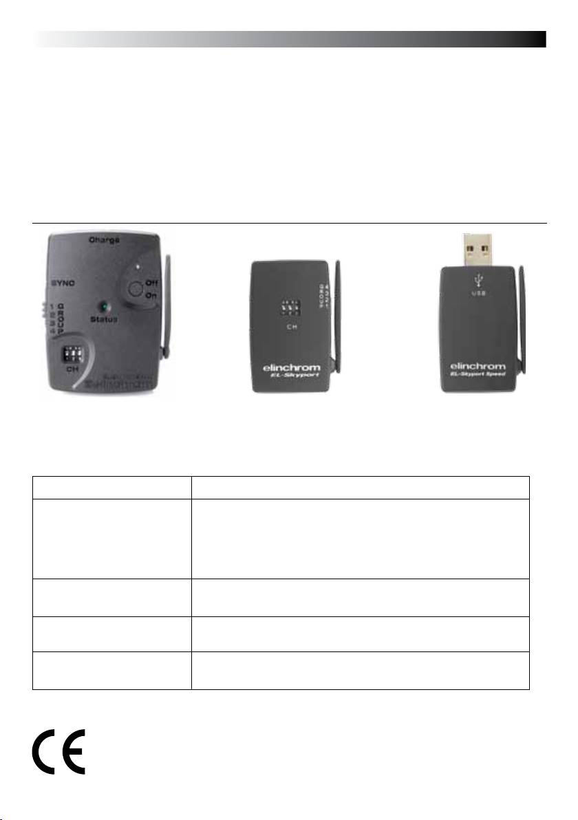
EL-Skyport Modules
EL-Skyport Universal SPEED (NEW) / Universal (previous version)
• Universal Receiver for all makes of Flash having a SYNC socket, conforming to Sync norms!
EL-Skyport Transceiver RX
• This Transceiver is only for Elinchrom RX units. The module operates all RX
features with the EL-Skyport / ERS- software 3.0 and triggers the ash
EL-Skyport USB RX SPEED (NEW) / USB RX (previous version)
• To operate RX ash units via computer the USB module should be used together
with the EL-Skyport Transceiver RX and the ERS- software 3.0
Universal Speed
Transceiver RX
USB RX Speed
& USB RX
& Universal
19353
Troubleshooting
Should an error occur, rst check the following points:
Having this problem? Check the following points:
No Flash unit can be triggered
Check if the Transmitter is switched ON
with the Transmitter
Check battery polarity
Check if the Receiver module is connected correctly to the unit
Check if the frequency selector switch is set to the same channel
Check if Transmitter is in the same trigger mode Speed or Standard.
Some units do not re when trig-
Reduce distance to any “not working” unit.
gered with the Transmitter
Check if Transmitter is in the same trigger mode Speed / Standard.
TEST ash works, but the camera
Check hot-shoe tting
will not trigger Flash unit
Limited Distance range
Reposition the unit
Increase the distance to walls and ceilings
CE Statements
This device has been tested and found to comply with the requirements set
up in the council directive on the approximation of the law of member states relating
to EMC Directive 89/336/EEC, Low Voltage Directive 73/23/EEC and R&TTE Directive
99/5/EC
19
